EP3342971B1 - Fenêtre ou porte dotées d'un châssis d'ouvrant pourvu d'un support de verre - Google Patents
Fenêtre ou porte dotées d'un châssis d'ouvrant pourvu d'un support de verre Download PDFInfo
- Publication number
- EP3342971B1 EP3342971B1 EP17208730.6A EP17208730A EP3342971B1 EP 3342971 B1 EP3342971 B1 EP 3342971B1 EP 17208730 A EP17208730 A EP 17208730A EP 3342971 B1 EP3342971 B1 EP 3342971B1
- Authority
- EP
- European Patent Office
- Prior art keywords
- corner
- window
- profiles
- legs
- glass support
- Prior art date
- Legal status (The legal status is an assumption and is not a legal conclusion. Google has not performed a legal analysis and makes no representation as to the accuracy of the status listed.)
- Active
Links
Images





Classifications
-
- E—FIXED CONSTRUCTIONS
- E06—DOORS, WINDOWS, SHUTTERS, OR ROLLER BLINDS IN GENERAL; LADDERS
- E06B—FIXED OR MOVABLE CLOSURES FOR OPENINGS IN BUILDINGS, VEHICLES, FENCES OR LIKE ENCLOSURES IN GENERAL, e.g. DOORS, WINDOWS, BLINDS, GATES
- E06B3/00—Window sashes, door leaves, or like elements for closing wall or like openings; Layout of fixed or moving closures, e.g. windows in wall or like openings; Features of rigidly-mounted outer frames relating to the mounting of wing frames
- E06B3/54—Fixing of glass panes or like plates
- E06B3/5409—Means for locally spacing the pane from the surrounding frame
-
- E—FIXED CONSTRUCTIONS
- E06—DOORS, WINDOWS, SHUTTERS, OR ROLLER BLINDS IN GENERAL; LADDERS
- E06B—FIXED OR MOVABLE CLOSURES FOR OPENINGS IN BUILDINGS, VEHICLES, FENCES OR LIKE ENCLOSURES IN GENERAL, e.g. DOORS, WINDOWS, BLINDS, GATES
- E06B3/00—Window sashes, door leaves, or like elements for closing wall or like openings; Layout of fixed or moving closures, e.g. windows in wall or like openings; Features of rigidly-mounted outer frames relating to the mounting of wing frames
- E06B3/54—Fixing of glass panes or like plates
-
- E—FIXED CONSTRUCTIONS
- E06—DOORS, WINDOWS, SHUTTERS, OR ROLLER BLINDS IN GENERAL; LADDERS
- E06B—FIXED OR MOVABLE CLOSURES FOR OPENINGS IN BUILDINGS, VEHICLES, FENCES OR LIKE ENCLOSURES IN GENERAL, e.g. DOORS, WINDOWS, BLINDS, GATES
- E06B3/00—Window sashes, door leaves, or like elements for closing wall or like openings; Layout of fixed or moving closures, e.g. windows in wall or like openings; Features of rigidly-mounted outer frames relating to the mounting of wing frames
- E06B3/04—Wing frames not characterised by the manner of movement
- E06B3/263—Frames with special provision for insulation
- E06B3/2632—Frames with special provision for insulation with arrangements reducing the heat transmission, other than an interruption in a metal section
-
- E—FIXED CONSTRUCTIONS
- E06—DOORS, WINDOWS, SHUTTERS, OR ROLLER BLINDS IN GENERAL; LADDERS
- E06B—FIXED OR MOVABLE CLOSURES FOR OPENINGS IN BUILDINGS, VEHICLES, FENCES OR LIKE ENCLOSURES IN GENERAL, e.g. DOORS, WINDOWS, BLINDS, GATES
- E06B3/00—Window sashes, door leaves, or like elements for closing wall or like openings; Layout of fixed or moving closures, e.g. windows in wall or like openings; Features of rigidly-mounted outer frames relating to the mounting of wing frames
- E06B3/96—Corner joints or edge joints for windows, doors, or the like frames or wings
- E06B3/964—Corner joints or edge joints for windows, doors, or the like frames or wings using separate connection pieces, e.g. T-connection pieces
-
- E—FIXED CONSTRUCTIONS
- E06—DOORS, WINDOWS, SHUTTERS, OR ROLLER BLINDS IN GENERAL; LADDERS
- E06B—FIXED OR MOVABLE CLOSURES FOR OPENINGS IN BUILDINGS, VEHICLES, FENCES OR LIKE ENCLOSURES IN GENERAL, e.g. DOORS, WINDOWS, BLINDS, GATES
- E06B7/00—Special arrangements or measures in connection with doors or windows
- E06B7/16—Sealing arrangements on wings or parts co-operating with the wings
- E06B7/22—Sealing arrangements on wings or parts co-operating with the wings by means of elastic edgings, e.g. elastic rubber tubes; by means of resilient edgings, e.g. felt or plush strips, resilient metal strips
-
- E—FIXED CONSTRUCTIONS
- E06—DOORS, WINDOWS, SHUTTERS, OR ROLLER BLINDS IN GENERAL; LADDERS
- E06B—FIXED OR MOVABLE CLOSURES FOR OPENINGS IN BUILDINGS, VEHICLES, FENCES OR LIKE ENCLOSURES IN GENERAL, e.g. DOORS, WINDOWS, BLINDS, GATES
- E06B3/00—Window sashes, door leaves, or like elements for closing wall or like openings; Layout of fixed or moving closures, e.g. windows in wall or like openings; Features of rigidly-mounted outer frames relating to the mounting of wing frames
- E06B3/04—Wing frames not characterised by the manner of movement
- E06B3/263—Frames with special provision for insulation
- E06B3/2632—Frames with special provision for insulation with arrangements reducing the heat transmission, other than an interruption in a metal section
- E06B2003/26325—Frames with special provision for insulation with arrangements reducing the heat transmission, other than an interruption in a metal section the convection or radiation in a hollow space being reduced, e.g. by subdividing the hollow space
Definitions
- the invention relates to a window or a door according to the preamble of claim 1.
- the corner glass support (s) designed in this way make it possible in a simple manner to safely carry off the pane load even on a casement frame which has no main profile on its composite profiles towards the outside.
- This construction is particularly useful if the insulating profiles of the casement do not have a fixed connection to a main profile towards the exterior, but are covered by a respective main profile of the frame, which closes or covers the rebate space to an exterior and directly via a seal comes into contact with the surface element.
- a particularly compact arrangement which on the other hand allows the corner glass support to be formed with a greater wall thickness and / or the grooves, is achieved in that at least the support sections of both legs of the at least one corner glass support are wholly or partially in each case in a recess, in particular in one Insert the receiving chamber of the respective insulating profile of the two insulating profiles that abut one another at a corner.
- this configuration can also be provided for several or preferably all of the corner glass supports.
- a rectangular frame is preferably implemented, and four corners with four corner glass supports are provided, which are further preferably all of the same design. It also preferably measures that are related to one of the legs and its arrangement. It is then preferred that these measures or arrangements are provided on both legs of the respective corner glass supports in the same way and are formed if necessary.
- corner glass supports is formed in one piece and / or if one or more of the corner glass supports consist of a metal sheet, in particular a steel sheet. But it can also consist of a light metal or plastic or another sufficiently strong material that can withstand the loads in the corner area and is coordinated with it. It can also be designed as a cast part.
- the main profile consists of metal, in particular of a light metal or a light metal alloy, or of plastic and / or that the insulating profile consists of plastic.
- one or both legs of the respective corner glass support have one or more beads or grooves. These preferably run parallel to the main direction of extension of the two legs of the at least one corner glass support.
- a further optimal stabilization of the at least one corner glass support is achieved in a simple manner in that the one or more beads or grooves according to the preceding paragraph each extend continuously over the corner area and both of the legs and / or that each has one or more the beads or grooves are provided both in the respective fastening section and in the respective support section of both legs.
- the fastening sections of both legs of the at least one corner glass support are each fixed to the main profiles of the respective frame profiles of the casement, which also abut one another corner.
- support means such as one or more glass rebate blocks and / or an adhesive are formed to bear part of the weight of the surface element in this section to support the leg or legs of the corner glass support.
- the at least one corner glass support is fastened on one or preferably both of its legs with the fastening sections of these legs on the respective main profiles by hooking the fastening sections behind an undercut on the main profiles.
- the center seal is preferably also in direct contact with this, which is also advantageous with regard to thermal insulation.
- the invention also realizes a simple and advantageous method for producing a window or a sash according to one of the claims relating thereto, with the steps of claim 16. Further advantageous refinements, each of which has a positive effect on the construction, can be found in the remaining subclaims.
- window can be replaced synonymously with the term "door”. Only the frame is often not closed all round on a door, but extends only over three sides of the frame. Terms such as “vertical” and “horizontal” or “right” and “left” refer to the representation of the Fig. 1 and an installation position on a vertically aligned wall, in particular on an outer wall of a building. In this respect, they are relative to the respective installation position.
- the three or four spars of the frame or casement frame to be described - these spars are also referred to below as frame profiles or composite frame profiles - are constructed here completely or essentially the same.
- the window 100 shown is designed for installation in an opening in a wall of a building. It has a frame 200 and a wing 300 with a wing frame 301.
- the wing 300 or the wing frame 301 is relative movable to the frame 200, in particular pivotable about a horizontal axis X and / or rotatable about a vertical axis of rotation Y (coordinate system shown displaced).
- the frame 200 and the casement 301 consist of horizontal and vertical frame profiles 201, 202, 203, 204 and 302, 303, 304, 305.
- the frame of a door can also be open at the lower edge (not shown here).
- the sash frame 301 also surrounds and supports a surface element 306 like a disk.
- 5 and 6 each show a section through the circumferential window frame and an edge of the surface element, i.e. through one of the casement profiles 302 and one of the frame profiles 201 and through an edge region of the surface element 306 close to a corner of the frame, in an area in which a (even closer to be described) corner glass support 320 extends. It is preferably close to the corners of all of the casement profiles and the frame profiles in the manner of 5 or 6 and possibly the variants and options described for this purpose, so that the following description can be transferred accordingly to the further frame sections.
- a (frame) rebate space F is formed between the frame 200 and the sash 301 on at least three sides of the window frame or all the way round, in which the frame 200 and the sash 301 are at a defined distance from one another when the window 100 is closed (see 5 and 6 ).
- the rebate area F is opened when the sash 300 is opened and, when the window 100 is closed, is essentially closed except for the remaining (narrow) gap sections SII and SI between the frame 200 and the sash frame 301 (except for functional openings to be explained below).
- Rotary and / or swivel bearings are used to implement a relative movement between the frame 200 and the casement 301.
- a handle can be provided for operation.
- the frame profiles 201-204 and the sash profiles 302-305 are designed as composite profiles.
- the frame profiles are preferably made (see also 5 and 6 ) from at least two main profiles 206, 207, which are connected here in one or more levels by one or more insulating webs 208, 209.
- the main profiles are preferably designed as metal profiles, in particular made of light metal or a light metal alloy.
- the insulating bars are made of plastic.
- the window frame can also consist entirely or partially of other materials.
- the two main profiles or one of the main profiles and the one or more insulating webs can also form a one-piece frame profile, in particular made of plastic.
- one of the main profiles 206 faces an exterior space I and the other of the main profiles 207 of the frame faces an interior space II in an opening of a building.
- the casement profiles have a main profile 307 (directed towards the interior in a preferred orientation) and an insulating profile 308 made of plastic, which is attached to or is formed on the main profile 307.
- the main profile 307 and the insulating profile 308 can thus be formed in one piece or in several pieces.
- the main profile 307 preferably consists of metal, in particular of a light metal or a light metal alloy. But it can also consist of plastic or another material.
- the main profile 307 preferably consists of metal, in particular of a light metal or a light metal alloy. But it can also consist of plastic or another material.
- the main profile 307 is preferably towards the interior I and the insulating profile 308 of the casement 301 towards the exterior. But it is on the outside of the main profile 207 of the frame 200, which closes or covers the rebate area F to the outside space I.
- the insulating profile 308 is frame-like spaced on the outside from the glass pane or surface element 306.
- a glass rebate GF is formed between the insulating profile 308 and the glass pane 306.
- a center seal 210 can be inserted into the rebate space F between the frame 200 and the sash frame 301, which is fixed here in the frame 200 and which, when the sash is closed, can preferably rest against the sash frame 301 with a web 211 (cf. 6a and 6b ).
- a groove cover profile 212 can also be formed on the frame 200, which engages with a foot 213 in a mounting groove 214 of the frame and which can be used in sections in uncovered sections for fittings.
- the show Fig. 3 and 5 or 2 and 6 two different variants 212 and 212 'of the groove cover profile, which differ essentially in that they extend into the rebate space F from the mounting groove 214 to different lengths. They can have a lateral web 215 with which they bear against the center seal 211.
- the web 215 preferably forms a common plane or surface with the side of the center seal 210 facing away from the frame.
- the groove cover profile 212 'of Fig. 6 practically forms a larger hollow chamber with the frame 200. And a further hollow chamber is formed below the web 215 towards the frame 200. It therefore optimizes the thermal insulation of the structure well.
- the groove cover profile 212 is also advantageous in terms of thermal insulation due to the web 215, since a kind of hollow chamber is also formed below this web towards the frame. It can also be cleaned particularly well.
- the groove cover profiles 212 and 212 'thus differ on the one hand by their appearance. On the other hand, they offer further advantages in terms of good thermal insulation and / or in terms of the possibility of cleaning the fold area.
- a cover leg 216 is also formed, which in the closed state of the window covers the outer edge of the surface element 306 of the wing 300 to the outer space I.
- a glass contact seal 217 is formed on the inside of the cover leg 216 and bears in the edge portion of the surface element 306 when the wing 300 is closed. When opening the wing 300 to the interior, this seal remains on the cover leg 206 of the frame 200.
- the insulating profile 308 of the casement 301 is preferably connected to the main profile 307 of the casement 301 in a shear-resistant manner, for example in the section of a fastening foot 309, which can be inserted into a fastening groove 310 of the main profile 307 and can be fixed there in a thrust-resistant manner by rolling.
- no further main profile is preferably provided towards the interior.
- the two basic elements are the main profiles 307 and the insulating profiles 308 attached to them.
- An outer shell, in particular made of metal, or an outer profile, particularly made of metal, is not provided here.
- the frame 200 is preferably in direct contact with the glass contact seal 217 on the surface element 306 of the wing 300 in the closed state of the window.
- the insulating profile 308 of the casement 301 preferably has a hollow chamber 311. This is preferably outside the circumferential edge of the surface element 306.
- the insulating profile 308 also preferably has such an extension in the direction Z between the outer space I and the interior II (parallel to the edge of the surface element 306) that it extends the pane edge of the surface element 306 laterally to the glass rebate GF completely covered.
- the surface element 306 Towards one side - here towards the interior II - the surface element 306 preferably bears against the main profile 307 of the casement frame via a strip, in particular a glass retaining strip 312 made of plastic, which is attached to the main profile 307, which in this respect is the surface element 306 Interior covered in a (narrow) edge section.
- the glass holding strip 312 can have a sealing lip 313 on the side, which lies against the surface element 306 and advantageously realizes a seal between the glass holding strip 312 and the surface element 306 in this area.
- the glass retaining strip 312 is fastened to the main profile 307, preferably with a foot 316 inserted into a groove 315 of the main profile 307. Between the glass retaining strip 312 and the surface element 306 - in particular the glass pane - an edge bond 314 can be formed in this section all around in sections or completely in the manner of a frame his. This can be formed, for example, by a strip that is self-adhesive on both sides, or some other adhesive.
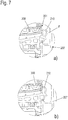
- corner glass support 320 in each case.
- a total of four of the corner glass supports 320 are preferably provided.
- the corner glass supports 302 each extend over a corner between adjoining casement profiles 302 and 303 or 303 and 304 or 304 and 305 or 305 and 302.
- Each corner glass support 320 is preferably designed as an angle element or angle support with two mutually angled, here right-angled legs 321, 322, which are connected to one another in a corner region 323 or preferably merge into one another ( Fig. 1b , Fig. 8 ).
- the legs 321, 322 are preferably constructed in the same way and are immediately connected to the corresponding wing frame profiles which abut one another at a corner.
- corner glass supports 320 is described below by way of example. All corner glass supports 320 can - but need not - advantageously be of the same design and corresponding and arranged on the respective casement profiles.
- the two legs 321, 322 of the corner glass support 320 are based on the corner area 323 (see Fig. 4 and 8th ) preferably at least 80 mm long.
- the maximum length is preferably ... mm.
- the corner glass support 320 is preferably formed in one piece from a metal sheet, in particular from a steel sheet. This preferably has a thickness of at least 1.4 mm - 8 mm.
- the two legs 321, 322 point each have a support section 321a, 322a for supporting the glass pane edge (this section rests on the respective insulating profile 308) and a fastening section 321b, 322b (which is fixed to the respective main profile 307 and, if appropriate, bears against it).
- These two sections 321a, 322a and 321b, 322b preferably each extend over the entire length of the two legs 321, 322, preferably in one piece or in one piece, directly next to one another and also over the corner area 323. This can be clearly seen in the cross-sectional views of FIG 5 and 6 .
- Fig. 4 and 8th referred.
- the corner glass supports 320 are each simply and advantageously suspended in the main profiles 307 of the frame profiles 302-305.
- the support sections 321a, 322a are advantageously spaced on the outside from the peripheral edge of the surface element 306.
- the metal sheet from which the corner glass support 320 is made preferably has one or more beads or grooves 324 in the support sections 321a, 322a and / or in the fastening sections 321b, 322b that run parallel to the respective frame profiles and the main direction of extension of the respective legs 321, 322 , 325 on.
- These one or more beads or grooves 324, 325 each serve to stiffen the two legs 321, 322 in order to protect them against bending, as could occur according to the prior art (see Fig. 1c ).
- the corner glass support 320 is so stable that such deflection no longer occurs to a relevant extent.
- both the legs 321, 322 and the corner area 323 preferably have grooves 324, 325 running continuously.
- the grooves 324, 325 are preferably at least 1.5 mm deep and 3 mm wide in order to ensure sufficient stabilization of the respective corner glass support 320.
- the grooves 324, 325 are particularly advantageous in this respect. However, they are not mandatory. If the metal sheet for the corner glass support 320 is chosen thick enough, it can also be omitted (not shown. The metal sheet can then advantageously be a steel sheet and at least a thickness of 2 mm or more with a weight of the surface element of 10 kg or more and one Have length of the frame profiles of more than 600 mm.
- the corner glass support (s) 320 are made of metal, in particular steel. However, they can also consist of a light metal or plastic or some other sufficiently strong material that can withstand the loads in the corner area and is coordinated with them.
- grooves 324, 325 are each formed at least in the support sections 321a, 322a of the two legs 321, 322, which lie like a frame outside the surface element 306. However, they are preferably also formed in the fastening sections 321b, 322b in order to stabilize them as well.
- a wall 326 of the hollow chambers 311 of the insulating profiles 308 of the respective corner of the sash frame 301 facing the glass rebate GF in the sections in which the adjacent sash frame profiles (for example 305, 302, see Fig. 4 ) the corner glass support 320 is to be arranged, has been removed from the insulating profiles 308 of the casement (see in particular Fig. 8 ).
- a receiving chamber 327 is advantageously formed in each of these sections, into which the support sections 321a, 322a of the two legs 321, 322 of the corner glass carrier 320 are inserted can. Since the corner glass carrier 320 lies in sections in each case (cleverly accommodated) in the receiving chambers 327, it is particularly advantageously possible to to make the corner glass support 320 relatively large in this section with a relatively large wall thickness, so to provide it with the grooves 324, 325 and / or to form it from a very thick or strong metal sheet, and to make it so stable that it is good against deflection is protected.
- support means such as one or more glass rebate blocks 328 ( Fig. 1b ) be designed to support the pane weight in this section on one or both legs 321, 322 of the corner glass support 320.
- an adhesive 328a ( 5, 6 between the corner glass support 320 and the pane edge of the surface element 306 can be provided in the region of one or both support sections of the legs 321, 322.
- corner glass carrier 320 is fastened to the main profile 307 on one or preferably both of its legs 321, 322 with the fastening sections 321b, 322b of these legs 321, 322.
- This fastening is preferably carried out directly simply by hanging the fastening sections 321b, 322b behind an undercut on the main profiles 307.
- the respective undercut can be formed by a free web on the respective main profiles 307 outside of hollow chambers 330, 331, 332 of the main profiles 307 placed one on the other (not shown here).
- the respective main profile 307 has one or more of the hollow chambers 330, 331, 332. It is then possible to use at least one or preferably two or even more of these hollow chambers 331, 332 for hanging the fastening sections 321b, 322b. In this way, the respective fastening section 321b, 322b of the two legs 321, 322 is accommodated, at least in sections, in a particularly space-saving manner and is nevertheless locked in place.
- fastening sections 321b, 322b have hook-like ends 335, 336 (see, for example, Fig. 5 and 8th ) exhibit.
- the hook-like ends 335, 336 are preferably designed as bends. It can also be provided that the grooves 325 also extend over the entire width of the fastening sections.
- the hook-like ends 335, 336 are hooked behind the undercuts (here the webs 337).
- the slot or slots 333 and / or 334 of the opened hollow chambers extend into the area of a miter cut.
- the corner glass support 320 is then inserted into the two sash profiles before the sash frame profiles are joined, in particular inserted into the slot (s) 333, 334, in particular with the hook-like end (s). Only then will the sash frame profiles to be connected via a corner (e.g. 302, 303) are assembled and / or joined in the corner area.
- At least one of the beads or grooves 325 is preferably additionally supported at another point on the respective main profile 307 of the casement 301.
- the respective fastening section 321b or 322b of the corner glass support 320 is stably hooked onto the respective associated main profile 302 to 305, and on the other hand, advantageously, a force transfer of part of the weight of the surface element 306 via the glass rebate blocks 328 and the corner glass support 320 into the main profiles 307 Casement profiles 302 to 305 possible.
- the fastening sections 321b, 322b are also preferably formed in one piece or connected to one another across the corner region 323. In this way, a very stable corner glass support 320 is created, which can be easily mounted on the casement 301, which does not impair the appearance of the casement 301 due to its clever accommodation, and is nevertheless designed to be very stable.
- the casement profiles 302-305 and the frame profiles 201-204 are preferably mitred in the corner area and placed at right angles to one another in these areas.
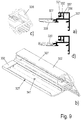
- corner connectors 340 are preferably used in order to additionally connect the sash frame profiles (for example 304, 305) which are placed next to one another in a corner.
- sash frame profiles for example 304, 305
- Fig. 11 This is exemplified in Fig. 11 to recognize.
- the corner connectors 340 are provided as angle elements, the legs of which are inserted into preferably otherwise free hollow chambers 330 of the two abutting sash profile sections (for example: 302, 33).
- corner connectors 340 can also optionally be used according to the invention.
- corner connectors 340 it is also possible according to the invention to dispense with the corner connectors 340 if the corner areas of the casement frames are adequately stabilized with the corner glass supports 320, for example on smaller windows 100 100 can also be achieved in this regard. It can easily be determined in an experiment whether additional corner connectors 340 should be used above or not.
- One or more holes 338, in particular bores in one or the two legs 321, 322 and / or corresponding holes 341 in the insulating profiles 308 can optimize the water drainage or serve to fix it, in particular in connection with one or more screws 339.
- Frame profiles 201, 202, 203, 204 Main profiles 206, 207 Insulating bars 208, 209 Center seal 210 web 211 Groove cover profile 212, 212 ' foot 213 Mounting groove 214 web 215 Cover leg 216 Glass system gasket 217 wing 300 Casement 301 Frame profiles 302, 303, 304, 305 Surface element 306 Main profile 307 Insulating profile 308 Mounting foot 309 Mounting groove 310 Hollow chamber 311 Glass retaining strip 312 Sealing lip 313 Edge gluing 314 Groove 315 foot 316 Corner glass support 320 leg 321.322 Support sections 321a, 322a Fastening sections 321b, 322b Corner area 323 Beads or
Landscapes
- Engineering & Computer Science (AREA)
- Civil Engineering (AREA)
- Structural Engineering (AREA)
- Physics & Mathematics (AREA)
- Thermal Sciences (AREA)
- Securing Of Glass Panes Or The Like (AREA)
Claims (16)
- Fenêtre (100) ou porte avec un châssis dormant (200) formé de profilés de châssis dormant (201 à 204) assemblés les uns aux autres dans les coins et d'un battant (300) mobile par rapport au châssis dormant (200) avec un châssis de battant (301) formé de profilés de châssis de battant (302 à 305) assemblés les uns aux autres dans les coins et avec un élément plan (306) fixé au châssis de battant, dans lequel un espace de feuillure (F) est formé entre le châssis dormant (200) et le châssis de battant (301) quand le battant (300) est fermé et dans lequel au moins chaque profilé de châssis de battant (301) comporte un profilé principal (307) et un profilé isolant (308) fixé ou formé sur celui-ci, un support de vitrage d'angle (320) étant disposé dans un ou plusieurs des coins du châssis de battant (301), en particulier tous, et comportant deux bras (321, 322) qui forment un angle l'un par rapport à l'autre, en particulier un angle droit, qui sont assemblés l'un à l'autre dans une zone de coin (323) et dont l'un ou les deux bras (321, 322) comporte une partie de fixation (321a, 322a) pour la fixation sur un des profilés principaux (307) jointifs les uns des autres des profilés de châssis de battant, et les deux bras (321, 322) comportant une partie d'appui (321b, 322b) pour reposer sur un des profilés isolants (308) jointifs les uns des autres des profilés de châssis de battant, caractérisée en ce qu'au moins les parties d'appui (321a, 322a) des deux bras (321, 322) de l'au moins un support d'angle de vitrage (320) reposent chacune entièrement ou en partie dans un creux, en particulier dans un compartiment de logement (327), du profilé isolant (308) correspondant.
- Fenêtre ou porte selon la revendication 1, caractérisée en ce que les profilés isolants (308) du châssis de battant (301) sont couverts par rapport à l'espace extérieur par un profilé principal (207) correspondant du châssis dormant (200) qui ferme ou couvre l'espace de feuillure F par rapport à un espace extérieur (I).
- Fenêtre (100) ou porte selon la revendication 1 ou 2, caractérisée en ce que l'au moins un support d'angle de vitrage (320) est formé d'une seule pièce.
- Fenêtre ou porte selon la revendication 2 ou 3, caractérisée en ce qu'un bras ou les deux bras (321, 322) de l'au moins un support d'angle de vitrage (320) présentent une ou plusieurs moulures ou rainures (324, 325) et en ce que celles-ci sont de préférence parallèles au sens d'étendue principal des deux bras et/ou en ce que l'une ou les plusieurs moulures ou rainures (324, 325) s'étendent de façon continue dans la zone de coin (323) et les deux bras (321 et 322) de l'au moins un support d'angle de vitrage (320) et/ou en ce que chacune des une ou plusieurs moulures ou rainures (324, 325) est prévue dans la partie de fixation (321b, 322b) correspondante et dans la partie d'appui (321a, 322a) correspondante des deux bras (321, 322) de l'au moins un support d'angle de vitrage (320).
- Fenêtre ou porte selon l'une des revendications précédentes, caractérisée en ce que les parties de fixation (321b, 322b) des deux bras (321, 322) de l'au moins un support d'angle de vitrage (320) sont fixées chacune sur les profilés principaux (307) des profilés de châssis correspondants du châssis de battant (301), en particulier accrochées.
- Fenêtre ou porte selon l'une des revendications précédentes, caractérisée en ce que les deux bras (321, 322) de l'au moins un support d'angle de vitrage (320) ont une longueur à partir de la zone de coin (323) d'au moins 80 mm et au maximum de préférence 250 mm chacun et/ou en ce que l'au moins un support d'angle de vitrage (320) se compose d'une tôle métallique présentant de préférence une épaisseur d'au moins 1,4 mm.
- Fenêtre ou porte selon l'une des revendications précédentes, caractérisée en ce que sont formés entre l'au moins un support d'angle de vitrage (320) et le bord de vitre de l'élément plan (306), au niveau d'une ou des deux parties d'appui (321a, 322a) des bras (321, 322), des moyens de support tels qu'un ou plusieurs blocs de rainure à verre (328) et/ou un collage (328a) destinés à supporter une partie du poids de l'élément plan (306) dans cette partie sur le ou les bras (321, 322) du support d'angle de vitrage (320).
- Fenêtre ou porte selon l'une des revendications précédentes, caractérisée en ce qu'au moins un support d'angle de vitrage (320) est fixé sur un ou de préférence les deux de ses bras (321, 322), avec les parties de fixation (321b, 322b) de ces bras (321, 322), sur les profilés principaux (307) jointifs l'un de l'autre en angle par l'accrochage des parties de fixation (321b, 322b) derrière une contre-dépouille sur les profilés principaux (307).
- Fenêtre ou porte selon l'une des revendications précédentes, caractérisée en ce que la contre-dépouille correspondante est une aile (337) dans ou sur au moins un compartiment creux (330, 331, 332) du profilé principal (307), ouvert entièrement ou au moins en partie.
- Fenêtre ou porte selon l'une des revendications précédentes, caractérisée en ce que les parties de fixation (321b, 322b) des bras (321, 322) de l'au moins un support d'angle de vitrage (320) présentent des extrémités en forme de crochet (335, 336) et en ce que ces extrémités en forme de crochet (335, 336) sont accrochées derrière les contre-dépouilles, de préférence une ou plusieurs ailes (337), et/ou en ce qu'au moins une des moulures ou nervures (325) s'appuie alors en complément à un endroit sur le profilé principal (307) du châssis de battant (301) correspondant.
- Fenêtre ou porte selon l'une des revendications précédentes, caractérisée en ce qu'en complément de l'au moins un support d'angle de vitrage (320), des éléments d'assemblage d'angle (340) sont prévus sur les profilés de châssis du châssis de battant (301) jointifs l'un de l'autre en angle.
- Fenêtre ou porte selon l'une des revendications précédentes, caractérisée en ce que le profilé principal (307) et le profilé isolant (308) sont formés ensemble d'une pièce ou formés séparément en plusieurs parties.
- Fenêtre ou porte selon l'une des revendications précédentes, caractérisée en ce qu'est formé sur le châssis dormant (200) un bras de couverture (216) qui recouvre, quand la fenêtre est fermée, le bord extérieur de l'élément plan (306) du battant (300) par rapport à l'espace extérieur (I).
- Fenêtre ou porte selon l'une des revendications précédentes, caractérisée en ce qu'un joint d'étanchéité central (210) est disposé sur le châssis dormant (200) et en ce qu'un profilé de couverture de la rainure (212, 212') est disposé au moins par zones sur le châssis dormant (200) et en ce qu'une aile (215) du profilé de couverture de la rainure (212) est formé en affleurement avec le joint d'étanchéité central (210) et forme de préférence un compartiment creux avec le châssis dormant (200).
- Fenêtre ou porte selon la revendication 14, caractérisée en ce que l'aile (215) affleure avec la face supérieure du joint d'étanchéité central (210) et/ou en ce que le profilé de couverture de la rainure (212, 212') est affleure par ailleurs avec l'aile (215) sur sa face supérieure ou se trouve par ailleurs en dessous de l'aile (215) et/ou en ce que le joint d'étanchéité central repose directement sur le battant quand celui-ci est fermé.
- Procédé pour la fabrication d'une fenêtre ou d'un battant selon l'une des revendications précédentes, caractérisé en ce qu'il comprend les étapes suivantes pour la fabrication d'une zone de coin du châssis de battant (300) :a. préparation de deux profilés de châssis de battant (302, 303, ...) à assembler en coin et d'un support d'angle de vitrage (320), qui sont coupés en onglet ;b. formation d'une ou plusieurs fentes dans un ou plusieurs compartiments creux des profilés de châssis de battant (302, 303, ...), qui s'étendent jusqu'à la zone coupée en onglet ;c. insertion du support d'angle de vitrage (320) par au moins une extrémité en forme de crochet (335, 336) dans le ou les plusieurs compartiment(s) creux entaillés avant l'assemblage des profilés de châssis de battant (302, 303, ...) ; etd. réunion et/ou assemblage des profilés de châssis de battant (302, 303, ...) à assembler en angle au niveau de la découpe en onglet ;
caractérisée en ce quee. au moins les parties d'appui (321a, 322a) des deux bras (321, 322) de l'au moins un support d'angle de vitrage (320) sont posées chacune entièrement ou partiellement dans un creux, en particulier un compartiment de logement (327), du profilé isolant (308) correspondant.
Applications Claiming Priority (1)
| Application Number | Priority Date | Filing Date | Title |
|---|---|---|---|
| DE102016125922.5A DE102016125922A1 (de) | 2016-12-30 | 2016-12-30 | Fenster oder Tür mit einem Flügelrahmen mit einem Glasträger |
Publications (2)
| Publication Number | Publication Date |
|---|---|
| EP3342971A1 EP3342971A1 (fr) | 2018-07-04 |
| EP3342971B1 true EP3342971B1 (fr) | 2020-03-18 |
Family
ID=60781767
Family Applications (1)
| Application Number | Title | Priority Date | Filing Date |
|---|---|---|---|
| EP17208730.6A Active EP3342971B1 (fr) | 2016-12-30 | 2017-12-20 | Fenêtre ou porte dotées d'un châssis d'ouvrant pourvu d'un support de verre |
Country Status (3)
| Country | Link |
|---|---|
| EP (1) | EP3342971B1 (fr) |
| CN (1) | CN108266098B (fr) |
| DE (1) | DE102016125922A1 (fr) |
Family Cites Families (17)
| Publication number | Priority date | Publication date | Assignee | Title |
|---|---|---|---|---|
| NL7611442A (nl) * | 1976-10-15 | 1978-04-18 | Schelde Nv | Warmte-isolerend kombinatieprofiel. |
| DE3102563C2 (de) * | 1981-01-27 | 1986-07-24 | Helmar Dr.Dr. 8530 Neustadt Nahr | Wärmegedämmtes Fenster |
| DE8505873U1 (de) * | 1985-03-01 | 1986-03-27 | Nahr, Helmar, Dr.Dr., 8530 Neustadt | Wärmegedämmtes Fenster oder entsprechende, verglaste Tür |
| CH678747A5 (en) * | 1989-08-21 | 1991-10-31 | Hartmann & Co Ag | Hinging facade window - has blocking portion pressing glazing via channel-section against supporting seal |
| IT1258237B (it) * | 1992-11-05 | 1996-02-22 | Accessorio a squadra per il supporto di tasselli destinati al montaggio di una lastra di vetro in un serramento formato da profilati | |
| DE19541705C1 (de) * | 1995-11-09 | 1997-05-07 | Alco Systeme Gmbh | Glaseckwinkel |
| DE29907672U1 (de) * | 1999-04-30 | 1999-08-26 | ALCO-Systeme GmbH, 48163 Münster | Glaseckwinkel |
| IT1319254B1 (it) * | 2000-10-30 | 2003-09-26 | Hydro Aluminium Systems Spa | Profilato portante per un telaio di una finestra, elemento difissaggio di un vetro e guarnizione di tenuta, associati a detto |
| AT413859B (de) | 2003-03-21 | 2006-06-15 | Avl List Gmbh | Brennkraftmaschine |
| AT413850B (de) * | 2004-06-07 | 2006-06-15 | Bug Alutechnic Ag | Flügel |
| CN2926444Y (zh) * | 2006-06-30 | 2007-07-25 | 百乐(杭州)建材有限公司 | 内开式复合窗 |
| EP2450517A1 (fr) * | 2010-11-03 | 2012-05-09 | Cuhadaroglu Metal Sanayi Ve Pazarlama Anonim Sirketi | Système de porte et fenêtre comprenant une porte isolée thermiquement et système de fenêtre comprenant des profilés d'aluminium thermiquement isolés avec la parclose cachée, dont le joint est dessus |
| EP2642060B1 (fr) * | 2012-03-21 | 2020-07-08 | Hochuli Metallbau AG | Battant de fenêtre ou de porte |
| CH706318A1 (de) * | 2012-03-21 | 2013-09-30 | Hochuli Metallbau Ag | Fenster- oder Türflügel. |
| DE202013100101U1 (de) * | 2013-01-10 | 2013-02-22 | SCHÜCO International KG | Wärmedämmleiste und Rahmenprofil für ein Fenster, eine Tür, eine Fassade oder ein Lichtdach |
| DE102013100278A1 (de) * | 2013-01-11 | 2014-07-17 | SCHÜCO International KG | Verfahren und Vorrichtung zum Einsetzen einer Scheibe in einen Rahmen |
| DE202016104157U1 (de) * | 2016-07-28 | 2016-08-31 | PHI Technik für Fenster und Türen GmbH | Glasfalzeinlage |
-
2016
- 2016-12-30 DE DE102016125922.5A patent/DE102016125922A1/de not_active Withdrawn
-
2017
- 2017-12-20 EP EP17208730.6A patent/EP3342971B1/fr active Active
- 2017-12-27 CN CN201711438512.6A patent/CN108266098B/zh not_active Expired - Fee Related
Non-Patent Citations (1)
| Title |
|---|
| None * |
Also Published As
| Publication number | Publication date |
|---|---|
| CN108266098A (zh) | 2018-07-10 |
| DE102016125922A1 (de) | 2018-07-05 |
| EP3342971A1 (fr) | 2018-07-04 |
| CN108266098B (zh) | 2021-02-23 |
Similar Documents
| Publication | Publication Date | Title |
|---|---|---|
| EP3423663B1 (fr) | Porte, fenêtre ou élément de façade ainsi qu'ensemble de garniture pour un tel élément | |
| EP2594720B2 (fr) | Cadres de fenêtre et de porte escamotables avec différents matériaux à base de matériaux thermoplastiques pouvant être soudés | |
| EP2666948B1 (fr) | Agencement de cadre pour un panneau de porte sectionnelle | |
| DE202013105916U1 (de) | Fenster- oder Türflügel mit einer Haltevorrichtung zur Aufnahme eines flügelüberdeckenden Flächenelements | |
| EP2796652B1 (fr) | Dormant de porte | |
| EP3423662B1 (fr) | Montant de dormant et/ou montant de battant ainsi que porte, fenêtre ou élément de façade | |
| DE102009051070A1 (de) | Wandsystem | |
| CH714559B1 (de) | Bauelement zum Verschliessen einer Öffnung in einem Bauwerk, insbesondere Fensterelement. | |
| EP3342971B1 (fr) | Fenêtre ou porte dotées d'un châssis d'ouvrant pourvu d'un support de verre | |
| EP0730068B1 (fr) | Lucarne | |
| AT519973A4 (de) | Fensterrahmensystem | |
| DE29811431U1 (de) | Fenster, Tür, Fassadenelement o.dgl. | |
| DE102016125334A1 (de) | Fenster oder Tür mit einer Dichtungsanordnung und Falzdichtung | |
| EP2060726B1 (fr) | Profilé creux | |
| DE102017118275B4 (de) | Torvorrichtung und diese enthaltende Toranordnung | |
| DE102005037926B4 (de) | Fensteranordnung für mobile Räume und Nachrüstsatz dafür | |
| EP3140486B1 (fr) | Porte, fenêtre ou élément de façade comprenant un système d'étanchéité | |
| DE102014103650A1 (de) | Verfahren sowie Profilsystem zur Herstellung von Gebäudefenstern, Gebäudetüren | |
| EP3839191B1 (fr) | Porte coulissante et cadre de support de construction sèche dotée d'une porte coulissante | |
| EP1304444B1 (fr) | Fenêtre ou port monobloc pour d'ouvrants mur | |
| AT508592A1 (de) | Flügel für ein fenster oder eine tür mit einem rahmen | |
| DE4325121A1 (de) | Panzer für Rolltore, Rolläden, Jalousien o. dgl. | |
| DE2541040A1 (de) | Schaukasten | |
| DE20220923U1 (de) | Fenster oder Fenstertür mit einem Flügelrahmen und einem Blendrahmen | |
| DE2309661A1 (de) | Scharnier fuer ein schwingfluegelfenster |
Legal Events
| Date | Code | Title | Description |
|---|---|---|---|
| PUAI | Public reference made under article 153(3) epc to a published international application that has entered the european phase |
Free format text: ORIGINAL CODE: 0009012 |
|
| STAA | Information on the status of an ep patent application or granted ep patent |
Free format text: STATUS: THE APPLICATION HAS BEEN PUBLISHED |
|
| AK | Designated contracting states |
Kind code of ref document: A1 Designated state(s): AL AT BE BG CH CY CZ DE DK EE ES FI FR GB GR HR HU IE IS IT LI LT LU LV MC MK MT NL NO PL PT RO RS SE SI SK SM TR |
|
| AX | Request for extension of the european patent |
Extension state: BA ME |
|
| STAA | Information on the status of an ep patent application or granted ep patent |
Free format text: STATUS: REQUEST FOR EXAMINATION WAS MADE |
|
| 17P | Request for examination filed |
Effective date: 20181217 |
|
| RBV | Designated contracting states (corrected) |
Designated state(s): AL AT BE BG CH CY CZ DE DK EE ES FI FR GB GR HR HU IE IS IT LI LT LU LV MC MK MT NL NO PL PT RO RS SE SI SK SM TR |
|
| RIC1 | Information provided on ipc code assigned before grant |
Ipc: E06B 3/54 20060101AFI20190801BHEP |
|
| GRAP | Despatch of communication of intention to grant a patent |
Free format text: ORIGINAL CODE: EPIDOSNIGR1 |
|
| STAA | Information on the status of an ep patent application or granted ep patent |
Free format text: STATUS: GRANT OF PATENT IS INTENDED |
|
| INTG | Intention to grant announced |
Effective date: 20190910 |
|
| GRAS | Grant fee paid |
Free format text: ORIGINAL CODE: EPIDOSNIGR3 |
|
| GRAJ | Information related to disapproval of communication of intention to grant by the applicant or resumption of examination proceedings by the epo deleted |
Free format text: ORIGINAL CODE: EPIDOSDIGR1 |
|
| GRAL | Information related to payment of fee for publishing/printing deleted |
Free format text: ORIGINAL CODE: EPIDOSDIGR3 |
|
| STAA | Information on the status of an ep patent application or granted ep patent |
Free format text: STATUS: REQUEST FOR EXAMINATION WAS MADE |
|
| GRAR | Information related to intention to grant a patent recorded |
Free format text: ORIGINAL CODE: EPIDOSNIGR71 |
|
| STAA | Information on the status of an ep patent application or granted ep patent |
Free format text: STATUS: GRANT OF PATENT IS INTENDED |
|
| GRAA | (expected) grant |
Free format text: ORIGINAL CODE: 0009210 |
|
| STAA | Information on the status of an ep patent application or granted ep patent |
Free format text: STATUS: THE PATENT HAS BEEN GRANTED |
|
| INTC | Intention to grant announced (deleted) | ||
| AK | Designated contracting states |
Kind code of ref document: B1 Designated state(s): AL AT BE BG CH CY CZ DE DK EE ES FI FR GB GR HR HU IE IS IT LI LT LU LV MC MK MT NL NO PL PT RO RS SE SI SK SM TR |
|
| INTG | Intention to grant announced |
Effective date: 20200211 |
|
| REG | Reference to a national code |
Ref country code: GB Ref legal event code: FG4D Free format text: NOT ENGLISH |
|
| REG | Reference to a national code |
Ref country code: DE Ref legal event code: R096 Ref document number: 502017004282 Country of ref document: DE |
|
| REG | Reference to a national code |
Ref country code: AT Ref legal event code: REF Ref document number: 1246083 Country of ref document: AT Kind code of ref document: T Effective date: 20200415 Ref country code: IE Ref legal event code: FG4D Free format text: LANGUAGE OF EP DOCUMENT: GERMAN |
|
| REG | Reference to a national code |
Ref country code: NL Ref legal event code: FP |
|
| PG25 | Lapsed in a contracting state [announced via postgrant information from national office to epo] |
Ref country code: NO Free format text: LAPSE BECAUSE OF FAILURE TO SUBMIT A TRANSLATION OF THE DESCRIPTION OR TO PAY THE FEE WITHIN THE PRESCRIBED TIME-LIMIT Effective date: 20200618 Ref country code: FI Free format text: LAPSE BECAUSE OF FAILURE TO SUBMIT A TRANSLATION OF THE DESCRIPTION OR TO PAY THE FEE WITHIN THE PRESCRIBED TIME-LIMIT Effective date: 20200318 Ref country code: RS Free format text: LAPSE BECAUSE OF FAILURE TO SUBMIT A TRANSLATION OF THE DESCRIPTION OR TO PAY THE FEE WITHIN THE PRESCRIBED TIME-LIMIT Effective date: 20200318 |
|
| PG25 | Lapsed in a contracting state [announced via postgrant information from national office to epo] |
Ref country code: GR Free format text: LAPSE BECAUSE OF FAILURE TO SUBMIT A TRANSLATION OF THE DESCRIPTION OR TO PAY THE FEE WITHIN THE PRESCRIBED TIME-LIMIT Effective date: 20200619 Ref country code: BG Free format text: LAPSE BECAUSE OF FAILURE TO SUBMIT A TRANSLATION OF THE DESCRIPTION OR TO PAY THE FEE WITHIN THE PRESCRIBED TIME-LIMIT Effective date: 20200618 Ref country code: LV Free format text: LAPSE BECAUSE OF FAILURE TO SUBMIT A TRANSLATION OF THE DESCRIPTION OR TO PAY THE FEE WITHIN THE PRESCRIBED TIME-LIMIT Effective date: 20200318 Ref country code: SE Free format text: LAPSE BECAUSE OF FAILURE TO SUBMIT A TRANSLATION OF THE DESCRIPTION OR TO PAY THE FEE WITHIN THE PRESCRIBED TIME-LIMIT Effective date: 20200318 Ref country code: HR Free format text: LAPSE BECAUSE OF FAILURE TO SUBMIT A TRANSLATION OF THE DESCRIPTION OR TO PAY THE FEE WITHIN THE PRESCRIBED TIME-LIMIT Effective date: 20200318 |
|
| REG | Reference to a national code |
Ref country code: LT Ref legal event code: MG4D |
|
| PG25 | Lapsed in a contracting state [announced via postgrant information from national office to epo] |
Ref country code: SK Free format text: LAPSE BECAUSE OF FAILURE TO SUBMIT A TRANSLATION OF THE DESCRIPTION OR TO PAY THE FEE WITHIN THE PRESCRIBED TIME-LIMIT Effective date: 20200318 Ref country code: IS Free format text: LAPSE BECAUSE OF FAILURE TO SUBMIT A TRANSLATION OF THE DESCRIPTION OR TO PAY THE FEE WITHIN THE PRESCRIBED TIME-LIMIT Effective date: 20200718 Ref country code: SM Free format text: LAPSE BECAUSE OF FAILURE TO SUBMIT A TRANSLATION OF THE DESCRIPTION OR TO PAY THE FEE WITHIN THE PRESCRIBED TIME-LIMIT Effective date: 20200318 Ref country code: LT Free format text: LAPSE BECAUSE OF FAILURE TO SUBMIT A TRANSLATION OF THE DESCRIPTION OR TO PAY THE FEE WITHIN THE PRESCRIBED TIME-LIMIT Effective date: 20200318 Ref country code: EE Free format text: LAPSE BECAUSE OF FAILURE TO SUBMIT A TRANSLATION OF THE DESCRIPTION OR TO PAY THE FEE WITHIN THE PRESCRIBED TIME-LIMIT Effective date: 20200318 Ref country code: CZ Free format text: LAPSE BECAUSE OF FAILURE TO SUBMIT A TRANSLATION OF THE DESCRIPTION OR TO PAY THE FEE WITHIN THE PRESCRIBED TIME-LIMIT Effective date: 20200318 Ref country code: PT Free format text: LAPSE BECAUSE OF FAILURE TO SUBMIT A TRANSLATION OF THE DESCRIPTION OR TO PAY THE FEE WITHIN THE PRESCRIBED TIME-LIMIT Effective date: 20200812 Ref country code: RO Free format text: LAPSE BECAUSE OF FAILURE TO SUBMIT A TRANSLATION OF THE DESCRIPTION OR TO PAY THE FEE WITHIN THE PRESCRIBED TIME-LIMIT Effective date: 20200318 |
|
| REG | Reference to a national code |
Ref country code: DE Ref legal event code: R097 Ref document number: 502017004282 Country of ref document: DE |
|
| PLBE | No opposition filed within time limit |
Free format text: ORIGINAL CODE: 0009261 |
|
| STAA | Information on the status of an ep patent application or granted ep patent |
Free format text: STATUS: NO OPPOSITION FILED WITHIN TIME LIMIT |
|
| PG25 | Lapsed in a contracting state [announced via postgrant information from national office to epo] |
Ref country code: DK Free format text: LAPSE BECAUSE OF FAILURE TO SUBMIT A TRANSLATION OF THE DESCRIPTION OR TO PAY THE FEE WITHIN THE PRESCRIBED TIME-LIMIT Effective date: 20200318 Ref country code: ES Free format text: LAPSE BECAUSE OF FAILURE TO SUBMIT A TRANSLATION OF THE DESCRIPTION OR TO PAY THE FEE WITHIN THE PRESCRIBED TIME-LIMIT Effective date: 20200318 |
|
| 26N | No opposition filed |
Effective date: 20201221 |
|
| PG25 | Lapsed in a contracting state [announced via postgrant information from national office to epo] |
Ref country code: PL Free format text: LAPSE BECAUSE OF FAILURE TO SUBMIT A TRANSLATION OF THE DESCRIPTION OR TO PAY THE FEE WITHIN THE PRESCRIBED TIME-LIMIT Effective date: 20200318 |
|
| PG25 | Lapsed in a contracting state [announced via postgrant information from national office to epo] |
Ref country code: SI Free format text: LAPSE BECAUSE OF FAILURE TO SUBMIT A TRANSLATION OF THE DESCRIPTION OR TO PAY THE FEE WITHIN THE PRESCRIBED TIME-LIMIT Effective date: 20200318 |
|
| REG | Reference to a national code |
Ref country code: CH Ref legal event code: PL |
|
| PG25 | Lapsed in a contracting state [announced via postgrant information from national office to epo] |
Ref country code: MC Free format text: LAPSE BECAUSE OF FAILURE TO SUBMIT A TRANSLATION OF THE DESCRIPTION OR TO PAY THE FEE WITHIN THE PRESCRIBED TIME-LIMIT Effective date: 20200318 |
|
| PG25 | Lapsed in a contracting state [announced via postgrant information from national office to epo] |
Ref country code: IE Free format text: LAPSE BECAUSE OF NON-PAYMENT OF DUE FEES Effective date: 20201220 Ref country code: LU Free format text: LAPSE BECAUSE OF NON-PAYMENT OF DUE FEES Effective date: 20201220 |
|
| PG25 | Lapsed in a contracting state [announced via postgrant information from national office to epo] |
Ref country code: CH Free format text: LAPSE BECAUSE OF NON-PAYMENT OF DUE FEES Effective date: 20201231 Ref country code: LI Free format text: LAPSE BECAUSE OF NON-PAYMENT OF DUE FEES Effective date: 20201231 |
|
| PG25 | Lapsed in a contracting state [announced via postgrant information from national office to epo] |
Ref country code: TR Free format text: LAPSE BECAUSE OF FAILURE TO SUBMIT A TRANSLATION OF THE DESCRIPTION OR TO PAY THE FEE WITHIN THE PRESCRIBED TIME-LIMIT Effective date: 20200318 Ref country code: MT Free format text: LAPSE BECAUSE OF FAILURE TO SUBMIT A TRANSLATION OF THE DESCRIPTION OR TO PAY THE FEE WITHIN THE PRESCRIBED TIME-LIMIT Effective date: 20200318 Ref country code: CY Free format text: LAPSE BECAUSE OF FAILURE TO SUBMIT A TRANSLATION OF THE DESCRIPTION OR TO PAY THE FEE WITHIN THE PRESCRIBED TIME-LIMIT Effective date: 20200318 |
|
| PG25 | Lapsed in a contracting state [announced via postgrant information from national office to epo] |
Ref country code: MK Free format text: LAPSE BECAUSE OF FAILURE TO SUBMIT A TRANSLATION OF THE DESCRIPTION OR TO PAY THE FEE WITHIN THE PRESCRIBED TIME-LIMIT Effective date: 20200318 Ref country code: AL Free format text: LAPSE BECAUSE OF FAILURE TO SUBMIT A TRANSLATION OF THE DESCRIPTION OR TO PAY THE FEE WITHIN THE PRESCRIBED TIME-LIMIT Effective date: 20200318 |
|
| GBPC | Gb: european patent ceased through non-payment of renewal fee |
Effective date: 20211220 |
|
| PG25 | Lapsed in a contracting state [announced via postgrant information from national office to epo] |
Ref country code: GB Free format text: LAPSE BECAUSE OF NON-PAYMENT OF DUE FEES Effective date: 20211220 |
|
| P01 | Opt-out of the competence of the unified patent court (upc) registered |
Effective date: 20230815 |
|
| PGFP | Annual fee paid to national office [announced via postgrant information from national office to epo] |
Ref country code: NL Payment date: 20241115 Year of fee payment: 8 |
|
| PGFP | Annual fee paid to national office [announced via postgrant information from national office to epo] |
Ref country code: BE Payment date: 20241115 Year of fee payment: 8 |
|
| PGFP | Annual fee paid to national office [announced via postgrant information from national office to epo] |
Ref country code: AT Payment date: 20241115 Year of fee payment: 8 |
|
| PGFP | Annual fee paid to national office [announced via postgrant information from national office to epo] |
Ref country code: DE Payment date: 20251020 Year of fee payment: 9 |
|
| PGFP | Annual fee paid to national office [announced via postgrant information from national office to epo] |
Ref country code: FR Payment date: 20251203 Year of fee payment: 9 |
|
| PGFP | Annual fee paid to national office [announced via postgrant information from national office to epo] |
Ref country code: IT Payment date: 20251231 Year of fee payment: 9 |