EP3343040B1 - Compresseur rotatif et dispositif de circulation de réfrigérant le comprenant - Google Patents
Compresseur rotatif et dispositif de circulation de réfrigérant le comprenant Download PDFInfo
- Publication number
- EP3343040B1 EP3343040B1 EP15901940.5A EP15901940A EP3343040B1 EP 3343040 B1 EP3343040 B1 EP 3343040B1 EP 15901940 A EP15901940 A EP 15901940A EP 3343040 B1 EP3343040 B1 EP 3343040B1
- Authority
- EP
- European Patent Office
- Prior art keywords
- sliding vane
- gas injection
- rotary compressor
- injection hole
- cylinder
- Prior art date
- Legal status (The legal status is an assumption and is not a legal conclusion. Google has not performed a legal analysis and makes no representation as to the accuracy of the status listed.)
- Active
Links
Images


Classifications
-
- F—MECHANICAL ENGINEERING; LIGHTING; HEATING; WEAPONS; BLASTING
- F04—POSITIVE - DISPLACEMENT MACHINES FOR LIQUIDS; PUMPS FOR LIQUIDS OR ELASTIC FLUIDS
- F04C—ROTARY-PISTON, OR OSCILLATING-PISTON, POSITIVE-DISPLACEMENT MACHINES FOR LIQUIDS; ROTARY-PISTON, OR OSCILLATING-PISTON, POSITIVE-DISPLACEMENT PUMPS
- F04C18/00—Rotary-piston pumps specially adapted for elastic fluids
- F04C18/30—Rotary-piston pumps specially adapted for elastic fluids having the characteristics covered by two or more of groups F04C18/02, F04C18/08, F04C18/22, F04C18/24, F04C18/48, or having the characteristics covered by one of these groups together with some other type of movement between co-operating members
- F04C18/34—Rotary-piston pumps specially adapted for elastic fluids having the characteristics covered by two or more of groups F04C18/02, F04C18/08, F04C18/22, F04C18/24, F04C18/48, or having the characteristics covered by one of these groups together with some other type of movement between co-operating members having the movement defined in group F04C18/08 or F04C18/22 and relative reciprocation between the co-operating members
-
- F—MECHANICAL ENGINEERING; LIGHTING; HEATING; WEAPONS; BLASTING
- F04—POSITIVE - DISPLACEMENT MACHINES FOR LIQUIDS; PUMPS FOR LIQUIDS OR ELASTIC FLUIDS
- F04C—ROTARY-PISTON, OR OSCILLATING-PISTON, POSITIVE-DISPLACEMENT MACHINES FOR LIQUIDS; ROTARY-PISTON, OR OSCILLATING-PISTON, POSITIVE-DISPLACEMENT PUMPS
- F04C23/00—Combinations of two or more pumps, each being of rotary-piston or oscillating-piston type, specially adapted for elastic fluids; Pumping installations specially adapted for elastic fluids; Multi-stage pumps specially adapted for elastic fluids
- F04C23/001—Combinations of two or more pumps, each being of rotary-piston or oscillating-piston type, specially adapted for elastic fluids; Pumping installations specially adapted for elastic fluids; Multi-stage pumps specially adapted for elastic fluids of similar working principle
-
- F—MECHANICAL ENGINEERING; LIGHTING; HEATING; WEAPONS; BLASTING
- F04—POSITIVE - DISPLACEMENT MACHINES FOR LIQUIDS; PUMPS FOR LIQUIDS OR ELASTIC FLUIDS
- F04C—ROTARY-PISTON, OR OSCILLATING-PISTON, POSITIVE-DISPLACEMENT MACHINES FOR LIQUIDS; ROTARY-PISTON, OR OSCILLATING-PISTON, POSITIVE-DISPLACEMENT PUMPS
- F04C18/00—Rotary-piston pumps specially adapted for elastic fluids
- F04C18/30—Rotary-piston pumps specially adapted for elastic fluids having the characteristics covered by two or more of groups F04C18/02, F04C18/08, F04C18/22, F04C18/24, F04C18/48, or having the characteristics covered by one of these groups together with some other type of movement between co-operating members
- F04C18/34—Rotary-piston pumps specially adapted for elastic fluids having the characteristics covered by two or more of groups F04C18/02, F04C18/08, F04C18/22, F04C18/24, F04C18/48, or having the characteristics covered by one of these groups together with some other type of movement between co-operating members having the movement defined in group F04C18/08 or F04C18/22 and relative reciprocation between the co-operating members
- F04C18/356—Rotary-piston pumps specially adapted for elastic fluids having the characteristics covered by two or more of groups F04C18/02, F04C18/08, F04C18/22, F04C18/24, F04C18/48, or having the characteristics covered by one of these groups together with some other type of movement between co-operating members having the movement defined in group F04C18/08 or F04C18/22 and relative reciprocation between the co-operating members with vanes reciprocating with respect to the outer member
- F04C18/3562—Rotary-piston pumps specially adapted for elastic fluids having the characteristics covered by two or more of groups F04C18/02, F04C18/08, F04C18/22, F04C18/24, F04C18/48, or having the characteristics covered by one of these groups together with some other type of movement between co-operating members having the movement defined in group F04C18/08 or F04C18/22 and relative reciprocation between the co-operating members with vanes reciprocating with respect to the outer member the inner and outer member being in contact along one line or continuous surfaces substantially parallel to the axis of rotation
- F04C18/3564—Rotary-piston pumps specially adapted for elastic fluids having the characteristics covered by two or more of groups F04C18/02, F04C18/08, F04C18/22, F04C18/24, F04C18/48, or having the characteristics covered by one of these groups together with some other type of movement between co-operating members having the movement defined in group F04C18/08 or F04C18/22 and relative reciprocation between the co-operating members with vanes reciprocating with respect to the outer member the inner and outer member being in contact along one line or continuous surfaces substantially parallel to the axis of rotation the surfaces of the inner and outer member, forming the working space, being surfaces of revolution
-
- F—MECHANICAL ENGINEERING; LIGHTING; HEATING; WEAPONS; BLASTING
- F04—POSITIVE - DISPLACEMENT MACHINES FOR LIQUIDS; PUMPS FOR LIQUIDS OR ELASTIC FLUIDS
- F04C—ROTARY-PISTON, OR OSCILLATING-PISTON, POSITIVE-DISPLACEMENT MACHINES FOR LIQUIDS; ROTARY-PISTON, OR OSCILLATING-PISTON, POSITIVE-DISPLACEMENT PUMPS
- F04C23/00—Combinations of two or more pumps, each being of rotary-piston or oscillating-piston type, specially adapted for elastic fluids; Pumping installations specially adapted for elastic fluids; Multi-stage pumps specially adapted for elastic fluids
- F04C23/008—Hermetic pumps
-
- F—MECHANICAL ENGINEERING; LIGHTING; HEATING; WEAPONS; BLASTING
- F04—POSITIVE - DISPLACEMENT MACHINES FOR LIQUIDS; PUMPS FOR LIQUIDS OR ELASTIC FLUIDS
- F04C—ROTARY-PISTON, OR OSCILLATING-PISTON, POSITIVE-DISPLACEMENT MACHINES FOR LIQUIDS; ROTARY-PISTON, OR OSCILLATING-PISTON, POSITIVE-DISPLACEMENT PUMPS
- F04C28/00—Control of, monitoring of, or safety arrangements for, pumps or pumping installations specially adapted for elastic fluids
- F04C28/06—Control of, monitoring of, or safety arrangements for, pumps or pumping installations specially adapted for elastic fluids specially adapted for stopping, starting, idling or no-load operation
- F04C28/065—Capacity control using a multiplicity of units or pumping capacities, e.g. multiple chambers, individually switchable or controllable
-
- F—MECHANICAL ENGINEERING; LIGHTING; HEATING; WEAPONS; BLASTING
- F04—POSITIVE - DISPLACEMENT MACHINES FOR LIQUIDS; PUMPS FOR LIQUIDS OR ELASTIC FLUIDS
- F04C—ROTARY-PISTON, OR OSCILLATING-PISTON, POSITIVE-DISPLACEMENT MACHINES FOR LIQUIDS; ROTARY-PISTON, OR OSCILLATING-PISTON, POSITIVE-DISPLACEMENT PUMPS
- F04C28/00—Control of, monitoring of, or safety arrangements for, pumps or pumping installations specially adapted for elastic fluids
- F04C28/24—Control of, monitoring of, or safety arrangements for, pumps or pumping installations specially adapted for elastic fluids characterised by using valves controlling pressure or flow rate, e.g. discharge valves or unloading valves
- F04C28/26—Control of, monitoring of, or safety arrangements for, pumps or pumping installations specially adapted for elastic fluids characterised by using valves controlling pressure or flow rate, e.g. discharge valves or unloading valves using bypass channels
-
- F—MECHANICAL ENGINEERING; LIGHTING; HEATING; WEAPONS; BLASTING
- F04—POSITIVE - DISPLACEMENT MACHINES FOR LIQUIDS; PUMPS FOR LIQUIDS OR ELASTIC FLUIDS
- F04C—ROTARY-PISTON, OR OSCILLATING-PISTON, POSITIVE-DISPLACEMENT MACHINES FOR LIQUIDS; ROTARY-PISTON, OR OSCILLATING-PISTON, POSITIVE-DISPLACEMENT PUMPS
- F04C29/00—Component parts, details or accessories of pumps or pumping installations, not provided for in groups F04C18/00 - F04C28/00
- F04C29/0007—Injection of a fluid in the working chamber for sealing, cooling and lubricating
-
- F—MECHANICAL ENGINEERING; LIGHTING; HEATING; WEAPONS; BLASTING
- F04—POSITIVE - DISPLACEMENT MACHINES FOR LIQUIDS; PUMPS FOR LIQUIDS OR ELASTIC FLUIDS
- F04C—ROTARY-PISTON, OR OSCILLATING-PISTON, POSITIVE-DISPLACEMENT MACHINES FOR LIQUIDS; ROTARY-PISTON, OR OSCILLATING-PISTON, POSITIVE-DISPLACEMENT PUMPS
- F04C29/00—Component parts, details or accessories of pumps or pumping installations, not provided for in groups F04C18/00 - F04C28/00
- F04C29/12—Arrangements for admission or discharge of the working fluid, e.g. constructional features of the inlet or outlet
-
- F—MECHANICAL ENGINEERING; LIGHTING; HEATING; WEAPONS; BLASTING
- F04—POSITIVE - DISPLACEMENT MACHINES FOR LIQUIDS; PUMPS FOR LIQUIDS OR ELASTIC FLUIDS
- F04C—ROTARY-PISTON, OR OSCILLATING-PISTON, POSITIVE-DISPLACEMENT MACHINES FOR LIQUIDS; ROTARY-PISTON, OR OSCILLATING-PISTON, POSITIVE-DISPLACEMENT PUMPS
- F04C2240/00—Components
- F04C2240/30—Casings or housings
-
- F—MECHANICAL ENGINEERING; LIGHTING; HEATING; WEAPONS; BLASTING
- F04—POSITIVE - DISPLACEMENT MACHINES FOR LIQUIDS; PUMPS FOR LIQUIDS OR ELASTIC FLUIDS
- F04C—ROTARY-PISTON, OR OSCILLATING-PISTON, POSITIVE-DISPLACEMENT MACHINES FOR LIQUIDS; ROTARY-PISTON, OR OSCILLATING-PISTON, POSITIVE-DISPLACEMENT PUMPS
- F04C2240/00—Components
- F04C2240/50—Bearings
Definitions
- the present disclosure relates to a compressor device, and more particularly to a rotary compressor and a refrigeration cycle device having the same.
- the related technologies indicate that in some applications, for example, in heat pump application in low temperature environment, the decrease of the evaporating temperature will lead to the reduce of the capacity of a refrigeration cycle system, and the performance of an ordinary single-stage rotary compressor becomes too worse to use. If a solution of large-capacity enhanced vapor injection is adopted, the capacity of the refrigeration cycle system can be improved effectively, but an ordinary high displacement double-cylinder enhanced vapor injection rotary compressor still performs a double-cylinder operation in case of a small compression load, which makes the running efficiency worse.
- EP1605167A1 describes that a rotary closed type compressor is configured such that an inside of a case becomes high pressure, and the rotary closed type compressor comprises a first cylinder and a second cylinder having cylinder chambers in which eccentric rollers are housed, respectively, vanes which divide the cylinder chamber into two sections, respectively, and vane chambers in which back-face side end portions of the vanes are housed, respectively.
- the vane on the first cylinder side is pressed and biased by a spring member provided in the vane chamber, and the vane on the second cylinder side is pressed and biased according to pressure difference between case internal pressure introduced to the vane chamber and suction pressure or discharge pressure introduced to the cylinder chamber.
- CN101397998A relates to a sliding vane holding device of a rotary compressor and a controlling method thereof; a motor and a compressing component connected with the motor are arranged in a sealed shell in which the pressure is a high-pressure side; the compressing component comprises two cylinders, and an intermediate baffle is arranged between the cylinders; each cylinder are held in a cylinder cavity of a circular piston which can carry out a free eccentric rotation; the sliding of a sliding vane is set in a sliding vane groove; the rear end part of the sliding vane is held in a sliding vane cavity; the sliding vane is pressed, and the front end of the sliding vane is in contact with and closely follows with the outer diameter of the circular piston, wherein, a first sliding cavity is provided with a spring connected with the sliding vane.
- the sliding vane holding device is characterized in that a cross hole is arranged on a second cylinder; one end of the cross hole is at the high-pressure side, and the other end of the cross hole is at the sliding groove of the second cylinder; a first concave part with a diameter more than the diameter of the cross hole is arranged on the lateral motion surface of a second sliding vane corresponding to the cross hole; a second sliding vane cavity is communicated with one end of a pressure switching pipe, and the other end of the pressure switching pipe stretches out of the shell and is communicated with a pressure switching valve.
- a refrigerant jetting type rotary compressor comprises a motor, a compression mechanism and a jetting mechanism.
- the motor and the compression mechanism are arranged in a shell, the compression mechanism comprises a cylinder with a cylinder compression cavity, a main bearing and an auxiliary bearing are respectively arranged on two sides of the cylinder, gas refrigerant is injected into the cylinder compression cavity by the jetting mechanism, the jetting mechanism comprises a valve seat, a check valve, a mounting groove and a limiting structure, and the mounting groove is communicated with the cylinder compression cavity.
- the mounting groove is a first mounting groove
- the first mounting groove is disposed on the cylinder
- the limiting structure is a limiting block
- the valve seat, the limiting block and the check valve are disposed in the first mounting groove
- the first mounting groove is communicated with the cylinder compression cavity via a second gas injection hole arranged on the cylinder
- one end of a gas refrigerant injection tube is disposed in the cylinder.
- the refrigerant jetting type rotary compressor not only is applicable to a single-cylinder rotary compressor, but also is applicable to a double-cylinder rotary compressor.
- JP2013036442A describes that an injection mechanism is installed in a middle plate, and an injection passage is formed in the radial direction of cylinders.
- the rotary compressor includes a slide mechanism opening/closing injection ports communicating the injection passage with cylinder chambers by a slide valve. When the injection ports are opened, the slide valve retracts from the injection ports so as not to be located within the injection passage.
- Embodiments of the present disclosure seek to solve at least one of the problems existing in the related art to at least some extent. Therefore, the present disclosure aims to provide a rotary compressor that has advantages of a simple and reasonable structure, a high operating efficiency, a wide range of application, and an excellent low temperature heating effect.
- the present disclosure further provides a refrigeration cycle device comprising the above-identified rotary compressor.
- the rotary compressor comprises: a liquid reservoir; a housing disposed outside the liquid reservoir, in which an exhaust port is formed; a compression mechanism disposed within the housing; and a first direction control assembly comprising a first valve port connected to said another cylinder, a second valve port connected to the liquid reservoir, and a third valve port in communication with the exhaust hole, one of the second valve port and the third port being in communication with the first valve port.
- the compression mechanism comprises a main bearing, a cylinder assembly, an auxiliary bearing, two pistons and two sliding vanes, wherein the main bearing and the auxiliary bearing are disposed at both axial ends of the cylinder assembly respectively;
- the cylinder assembly comprises two cylinders having compression chambers, and a partition plate arranged between the two cylinders, on each of which a sliding vane groove, a gas suction hole and an exhaust hole are formed;
- each piston is disposed inside the corresponding compression chamber and capable of rolling along an inner wall of the compression chamber;
- each sliding vane is movably disposed inside the corresponding sliding vane groove, a head portion of the sliding vane of one of the two cylinders abutting against an outer circumferential wall of the corresponding piston, while the sliding vane of the other one of the two cylinders being optionally in contact with or separate from the corresponding piston.
- the compressor mechanism is provided with a first gas injection hole for injecting a refrigerant into the compression chamber of the one of the cylinder, and
- the rotary compressor according to the present disclosure has the advantages of the high operating efficiency, wide application range, and excellent low temperature heating effect.
- the rotary compressor according to the above embodiment of the present disclosure can also have the additional technological features.
- the first gas injection hole and the second gas injection hole are formed in the partition plate.
- the first gas injection hole and the second gas injection hole are formed in the main bearing and the auxiliary bearing respectively.
- the second gas injection hole is located at a side of the first gas injection hole adjacent to the exhaust hole in the rolling direction of the piston.
- the rotary compressor further comprises a one-way valve, disposed at the second gas injection hole and configured to unidirectionally inject the refrigerant into the compression chamber of said another cylinder.
- a tail portion of the sliding vane of the said another cylinder is provided with a sliding braking device; when the pressure difference between the tail portion of the sliding vane and the head portion of the sliding vane is greater than a braking force acted on the sliding vane by the sliding vane braking device, the sliding vane is separated from the sliding vane braking device, and the head portion of the sliding vane is pressed against the outer circumferential wall of the corresponding piston.
- the braking force is from 2N to 10N.
- the third valve port is directly connected to the exhaust port or an interior of the housing.
- the first direction control assembly is a three-way valve.
- the refrigeration cycle device comprises the rotary compressor according to embodiments of the first aspect of the present disclosure; a second direction control assembly comprising a first connector, a second connector, a third connector and a fourth connector, the first connector being connected to the exhaust port of the rotary compressor and the fourth connector being connected to the liquid reservoir; an outdoor heat exchanger having a first end connected to the second connector; an indoor heat exchanger having a first end connected to the third connector and a second end connected to a second end of the outdoor exchanger; and a flash tank connected between the second end of the indoor exchanger and the second end of the outdoor exchanger, wherein the flash tank is connected to the first gas injection hole and the second gas injection hole of the rotary compressor.
- the overall performance of the refrigeration cycle device may be improved.
- a rotary compressor 700 according to embodiments of the first aspect of the present disclosure will be described below with reference to Figs. 1-6 .
- the rotary compressor 700 includes: a liquid reservoir 1, a housing 2, a compression mechanism, and a first direction control assembly 49.
- the housing 2 is disposed outside the liquid reservoir 1 and formed with an exhaust port 21 therein.
- the rotary compressor 700 can be a vertical compressor, and hereby, the housing 2 can be substantially formed as a hollow and sealed cylindrical tube shape, with a central axis thereof extending in the vertical direction; the exhaust port 21 can penetrate a top wall of the housing 2 in an up-and-down direction, and an vertically extended exhaust pipe 22 can be inserted into the exhaust port 21 to discharge a gaseous refrigerant (or a mixture with part of liquid refrigerant and lubricating oil) from the interior of the housing 2; the liquid reservoir 1 is disposed outside the housing 2.
- the present invention is not limited thereto, i.e. the rotary compressor 700 can be a horizontal compressor, and hereby, the central axis of the housing 2 can extend in the horizontal direction. Only the rotary compressor 700 configured as the vertical compressor will be exemplified below.
- the compression mechanism is disposed within the housing 2, and includes a cylinder assembly, a main bearing 421 and an auxiliary bearing 422 disposed separately at both axial ends of the cylinder assembly.
- the main bearing 421 is disposed at the top of the cylinder assembly, while the auxiliary bearing 422 is disposed at the bottom of the cylinder assembly.
- the cylinder assembly comprises two cylinders provided with compression chambers, and a partition plate 453 arranged between the two cylinders. That is, the cylinder assembly includes two cylinders, the partition plate 453 is arranged between the two cylinders, and each of the two cylinders has a compression chamber. As shown in Figs. 1 and 2 , the cylinder assembly includes a first cylinder 451 disposed above the partition plate 453 and a second cylinder 452 disposed below the partition 453; the main bearing 421, the first cylinder 451, and the partition plate 453 define a first compression chamber 4511, while the partition plate 453, the second cylinder 452 and the auxiliary bearing 422 define a second compression chamber 4521.
- the compression mechanism also includes two pistons and two sliding vanes, each piston is disposed inside the corresponding compression chamber and capable of rolling along an inner wall of the compression chamber, and each sliding vane is movably disposed inside the corresponding sliding vane groove.
- a sliding vane groove, a gas suction hole and an exhaust hole are formed on each cylinder, in which the exhaust hole is directly or indirectly connected to the interior of the housing 2, and thereby connected to the exhaust port 21.
- the two sliding vanes are represented by a first sliding vane 471 and a second vane 472, and the two pistons are represented by a first piston 461 and a second piston 462; a first sliding vane groove 4512, a first gas suction hole 4513 and a first exhaust hole 4514 are formed on the first cylinder 451; the first piston 461 is disposed inside the first compression chamber 4511 and rolls along the inner wall of the first compression chamber 4511; the first sliding vane groove 4512 can extend in a radial direction of the first cylinder 451, and the first sliding vane 471 is movably disposed inside the first sliding vane groove 4512 along a length direction thereof; a second sliding vane groove 4522, a second gas suction hole 4523 and a second exhaust hole 4524 are formed on the second cylinder 452; the second piston 462 is disposed inside the second compression chamber 4521 and rolls along the inner wall of the second compression chamber 4521; the second sliding vane groove 4522 can extend in
- the head portion of the sliding vane of one of the two cylinders abuts against an outer circumferential wall of the corresponding piston, while the sliding vane of the other one of the two cylinders can be optionally in contact with or separate from the corresponding piston. That is, there are two possibilities: first, when the head portion of the first sliding vane 471 of the first cylinder 451 abuts against the outer circumferential wall of the first piston 461, the sliding vane 472 of the second cylinders 452 can optionally contact or separate from the second piston 462; second, when the head portion of the second sliding vane 472 of the second cylinder 452 abuts against the outer circumferential wall of the second piston 462, the sliding vane 471 of the first cylinders 451 can optionally contact or separate from the first piston 461.
- the head portion of the sliding vane can be construed as an end of the sliding vane adjacent to the central axis of the corresponding compression chamber, and the opposite end thereof is the tail portion of the sliding vane which away from the central axis of the corresponding compression chamber.
- a spring 481 may be provided between the tail portion of the first sliding vane 471 and inner side wall of the housing 2, and keep pushing the head portion of the first sliding vane 471 to abut against to the outer circumferential wall of the first piston 461;
- a braking device 482 may be provided between the tail portion of the second sliding vane 472 and the inner side wall of the housing 2, and control the head portion of the second sliding vane 472 to abut against the outer circumferential wall of the second piston 462 under some working conditions and control the head portion of the second sliding vane 472 to separate from the outer circumferential wall of the second piston 462 under other working conditions.
- the devices capable of controlling the first sliding vane 471 and the second sliding vane 472 are not limited to the spring 481 and the sliding braking device 482. Additionally, it shall be noted that the sliding braking device 482 will be described in detail below, and thus will not be described herein.
- a first gas injection hole 441 is formed and configured to inject the refrigerant into the compression chamber of one of the cylinders (i.e. the cylinder provided with the sliding vane with its head portion abutting against the outer circumferential wall of the piston), and a second gas injection hole 442 is formed and configured to unidirectionally inject the refrigerant into the compression chamber of the other cylinder (i.e. the cylinder provided with the sliding vane optionally in contact with or separate from the corresponding piston).
- a first gas injection hole 441 is formed and configured to inject the refrigerant into the compression chamber of one of the cylinders (i.e. the cylinder provided with the sliding vane with its head portion abutting against the outer circumferential wall of the piston)
- a second gas injection hole 442 is formed and configured to unidirectionally inject the refrigerant into the compression chamber of the other cylinder (i.e. the cylinder provided with the sliding vane optionally in contact with or separate from the corresponding piston).
- the compression mechanism is provided with the first gas injection hole 441 for injecting the refrigerant into the first compression chamber 4511 of the first cylinder 451, and the second injection hole 442 for unidirectionally injecting the refrigerant into the second compression chamber 4512 of the second cylinder 452.
- the term "injecting unidirectionally” can be construed as that the refrigerant in the second compression chamber 4521 will not flow back to the second gas injection hole 442.
- the specific position of the specific configurations of the first gas injection hole 441 and the second gas injection hole 442 will be described in detail below, and thus will not be described herein.
- a one-way valve 443 may be provided to realize a check function. That is, the rotary compressor 700 further includes the one-way valve 443 disposed at the second gas injection hole 442 and configured to unidirectionally inject the refrigerant into the compression chamber of said another cylinder (i.e. the cylinder provided with the sliding vane optionally in contact with or separate from the corresponding piston). As shown in Fig. 2 , the one-way valve 443 is disposed at the second gas injection hole 442 and configured to unidirectionally inject the refrigerant into the second compression chamber 4521 of the second cylinder 452, so as to prevent the refrigerant in the second compression chamber 4521 from flowing back to the second gas injection hole 442.
- the present disclosure is not limited thereby - other devices may be provided to realize the anti-backflow function.
- the first direction control assembly 49 includes a first valve port 491 connected to said another cylinder (i.e. the cylinder provided with the sliding vane optionally in contact with or separate from the corresponding piston), a second valve port 492 connected to the liquid reservoir 1, and a third valve port 493 in communication with the exhaust hole (i.e. the first exhaust hole 4514 or the second exhaust hole 4524), in which one of the second valve port 492 and the third port 493 is optionally in communication with the first valve port 491. That is, the second valve port 492 is in communication with the first valve port 491 under some working conditions (as shown in Fig.
- the first direction control assembly 49 is a three-way valve.
- the present disclosure is not limited thereby - the first direction control assembly 49 can also be configured as other structures capable of achieving the three-way switching effect.
- the third valve port 493 is in communication with the exhaust hole, and then may be in communication with the interior of the housing 2 and the exhaust port 21 since the exhaust hole is in communication with the interior of the housing 2 and the exhaust port 21. That is, the third valve port 493 can direct the exhaust pressure out of the exhaust pipe 22 or the sealed housing 2. As shown in Figs. 1 to 3 , the third valve port 493 is connected to the exhaust port 21, so as to be in communication with the exhaust hole. Alternatively, as shown in Fig. 6 , the third valve port 493 is connected to the interior of the housing 2, so as to be in communication with the exhaust hole. Therefrom, it is convenient to process and implement.
- the first gas suction 4513 of the first cylinder 451 is connected to and in communication with the liquid reservoir 1; the second gas suction hole 4523 of the second cylinder 452 is connected to and in communication with the first valve port 491 of the first direction control assembly 49; the first exhaust hole 4514 of the first cylinder 451 is directly in communication with the interior of the housing 2, or indirectly in communication with that by a first muffler 431 described below, and the second exhaust hole 4524 of the second cylinder 452 is directly in communication with the interior of the housing 2, or indirectly in communication with that by a second muffler 432 described below, so that the first exhaust hole 4514 and the second exhaust hole 4524 can be in communication with the exhaust port 21 via the interior of the housing 2.
- the second valve port 492 of the first direction control assembly 49 is connected and communicated with the liquid reservoir 1, and when the second valve port 492 is in communication with the first valve port 491, the liquid reservoir 1 can deliver the refrigerant to the second compression chamber 4521 through the second gas suction hole 4523.
- the third valve port 493 of the first direction control assembly 49 is in communication with the first exhaust hole 4514 or the second exhaust hole 4524. That is, the third valve port 493 of the first direction control assembly 49 is in communication with the interior of the housing 2 and the exhaust port 21, so that when the third valve port 493 is in communication with the first valve port 491, the second gas suction hole 4523 is in communication with the interior of the housing 2 and the exhaust port 21.
- two working modes can be achieved by switching between the two communication modes via the first direction control assembly 49, namely, a full load working mode and a part load working mode.
- the first direction control assembly 49 is configured to communicate the first valve port 491 with the second valve port 492, to communicate the second gas suction hole 4523 of the second cylinder 452 with the liquid reservoir 1.
- the low-pressure refrigerant with pressure Ps at the evaporation side of the refrigeration cycle device 1000 flows through the liquid reservoir 1, into the first cylinder 451 via the first gas suction hole 4513, and meanwhile, flows through the first direction control assembly 49 and the second gas suction hole 45223, into the second cylinder 452, in which case the first cylinder 451 and the second cylinder 452 both work normally.
- the low-pressure refrigerant flows into the interior of the sealed housing 2 respectively through the first exhaust hole 4514 and the second exhaust hole 4524, and is discharged from the exhaust pipe 22 at the exhaust port 21, after being compressed by the first cylinder 451 and the second cylinder 452 respectively, with the pressure increased to Pd, in which case the rotary compressor 700 is running in a double-cylinder manner and works in the full load working mode.
- the second cylinder 452 may work normally, in which case the enhanced vapor refrigerant with pressure Pm from the refrigeration cycle device 1000 may be injected into the first compression chamber 4511 via the first injection port 441, and meanwhile be unidirectionally injected into the second compression chamber 4521 via the second injection port 442, so as to achieve the double-cylinder injection operation of the rotary compressor 700.
- the first direction control assembly 49 is configured to communicate the first valve port 491 with the third valve port 493, so as to communicate the second gas suction hole 4523 of the second cylinder 452 with the interior of the housing 2 and the exhaust port 21.
- the low pressure refrigerant with pressure Ps from the evaporation side of the refrigeration cycle device 1000 enters the first cylinder 451 only via the first gas suction hole 4513 after flowing through the liquid reservoir 1, and then the first cylinder 451 works normally.
- the second gas suction hole 4523 is in communication with the interior of the housing 2 and the exhaust port 21, the interior of the second compression chamber 4521 has a high-pressure refrigerant, the pressure of the second gas suction hole 4523 is the high pressure Pd, and meanwhile the back pressure at the tail portion of the second sliding vane 472 is the high pressure Pd inside the sealed housing 2, so that the sliding vane 472 is stopped in the second sliding vane groove 4522 (as shown in Fig.
- the enhanced vapor refrigerant with pressure Pm from the refrigeration cycle device 1000 is injected into the first compression chamber 4511 via the first injection port 441, and meanwhile, the high-pressure refrigerant with pressure Pd of the interior of the second compression chamber is stopped by the one-way valve 443 and thus cannot flow to the second gas injection hole 442, so as to achieve the single-cylinder injection operation of the rotary compressor 700.
- the rotary compressor 700 can be the variable displacement enhanced vapor injection compressor, and can switch readily between the full load working mode and the part load working mode by providing the first direction control assembly 49 capable of switching between the two communication modes.
- the rotary compressor 700 can adopt the part load working mode when the load of the system is small, to make the system operate effectively, and when running in the full load working mode, the capacity of gas delivery of the rotary compressor 700 can be increased, so as to improve the heating effect in the low temperature heating application greatly.
- the rotary compressor 700 can have a more reasonable structure, a higher operating efficiency, a wider range of applications, and a more excellent low temperature heating effect.
- rotary compressor 700 according to some embodiments of the present disclosure is to be illustrated referring the Figs. 1 to 6 .
- the rotary compressor 700 can includes a housing 2, an electric motor 3 and a compression mechanism disposed in the housing 2; the electric motor 3 is connected to the compression mechanism that includes a first cylinder 451 on the top of which a main bearing 421 is disposed, a second cylinder 452 at the bottom of which an auxiliary bearing 422 is disposed, and a partition plate 453 which can consist of a first partition plate 4531 and a second partition plate 4532.
- the first cylinder 451 is formed with a first compression chamber 4511, and provided with a first piston 461 (rolling piston) rotating eccentrically in the first compression chamber 4511 of the first cylinder 451, and a first sliding vane 471 received in the first sliding vane groove 4512 and having a head portion (front end) in contact with the outer circumferential wall of the first piston 461 and a tail portion (rear end) provided with a spring 481.
- the second cylinder 452 is formed a second compression chamber 4521, and provided with a second piston 462 (rolling piston) rotating eccentrically in the second compression chamber 4521 of the second cylinder 452, and a second sliding vane 472 received in the second sliding vane groove 4522 and having a head portion (front end) optionally in contact with or separate from the outer circumferential wall of the second piston 462 and a tail portion (rear end) provided with a spring 482.
- the compression mechanism also includes a crankshaft 41 over which the first piston 461 and the second piston 462 are both fitted, so as to actuate the first piston 461 and the second piston 462 to roll at same time in the corresponding compression chambers by the crankshaft 41.
- the first cylinder 451 is formed with a first gas suction hole 4513 and a first exhaust hole 4514, and also provided with the a first gas suction pipe 11, one end of the first gas suction pipe 11 being connected to the first gas suction hole 4513, and the other end thereof being connected to the liquid reservoir 1;
- the first exhaust hole 4514 is in communication with the interior of the housing 2 via the first exhaust valve 4211 of the main bearing 421 and the first muffler 431.
- the second cylinder 452 is formed with a second gas suction hole 4523 and a second exhaust hole 4524, and also provided with a second gas suction pipe 12, one end of the second gas suction pipe 12 being connected to the second gas suction hole 4523, and the other end being optionally in communication with the liquid reservoir 1 and the exhaust port 21(or the interior of the housing 2) via the direction control assembly 49 (for example a three-way valve); the second exhaust hole 4524 is in communication with the interior of the housing 2 via the second exhaust valve of the auxiliary bearing 422 and the second muffler 432.
- the partition plate 453 is formed with a first gas injection hole 441 in communication with the first compression chamber 4511, and a second gas injection hole 442 in communication with the second compression chamber 4521. That is, the first gas injection hole 441 and the second gas injection hole 442 can be formed in the partition plate 453.
- first gas injection hole 441 and the second gas injection hole 442 can be formed in the partition plate 453.
- the rotary compressor 700 can also include the gas injection pipe 44; the first gas injection hole 441 and the second gas injection hole 442 are separately connected to the gas injection pipe 44, in which the one-way valve 443 is disposed between the second gas injection hole 442 and the gas injection pipe 44 and then gas can flow unidirectionally from the gas injection pipe 44 to the second gas injection hole 442 via the one-way valve 443, such that the first gas injection hole 441 and the second gas injection hole 442 can be periodically opened and closed following the rolling of the first piston 461 and the second piston 462 respectively. Therefrom, it is intended to facilitate the machining and the control over the opening and closing of the first gas injection hole 441 and the second gas injection hole 442.
- the first cylinder 451 Since in the two working modes of the rotary compressor 700, the first cylinder 451 is always in the working state, that is, the first cylinder 451 is required to work when the load is small.
- the injection termination time is earlier, the first gas injection hole 441 shall be closed earlier, but when the second cylinder 452 works at high load, the second gas injection hole 442 shall be closed later to increase the injection quantity.
- the second gas injection hole 442 should be located at the side of the first gas injection hole 441 adjacent to the corresponding exhaust hole in the rolling direction of the piston (since the projection of the first exhaust hole 4514 and that of the second exhaust hole 4524 on a datum plane mentioned hereinafter coincide, it is reasonable to interpret the exhaust hole herein as either of the first exhaust hole 4514 and the second exhaust hole 4524).
- the second gas injection hole 442 is closer to the exhaust hole in the compressor rotating direction compared with the first gas injection hole 441.
- the rotary compressor 700 can switch better and more effectively between the two working modes of the full load working mode and the part load working mode, and can have the more reasonable structure, higher operating efficiency, wider application range, and more excellent low temperature heating effect.
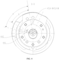
- the projections of the first exhaust hole 4514 and the second exhaust hole 4524 coincide; the intersection point of the center axis of the crankshaft 41 and the datum plane is considered as the origin, so that the angle A, defined between the connection line from the midpoint of the projection of the first exhaust hole 4514 (or the second exhaust hole 4524) on the datum plane to the origin, and the connection line from the end point of the projection of the first gas injection hole 441 on the datum plane to the origin, can represent the angle of the first gas injection hole 441 with respect to the first exhaust hole 4514 (or the second exhaust hole 4524); the angle B, defined between the connection line from the midpoint of the projection of the first exhaust hole 4514 (or the second exhaust hole 4524) on the datum plane to the origin, and the connection line from the end point of the projection of the second gas injection hole 442 on the datum plane to the origin, can represent the angle of the second gas injection
- the angle B is smaller than the angle A, so it can be construed as that the second injection port 442 is located at the side of the first gas injection hole 441 adjacent to the first exhaust hole 4514 (or the second exhaust hole 4524) in the rolling direction of the piston.
- the present disclosure is not limited thereby - as shown in Fig. 5 , the first gas injection hole 441 and the second gas injection hole 442 can also be formed in the main bearing 421 and the auxiliary bearing 422 respectively. That is, the first gas injection hole 441 is formed in the main bearing 421, and the second gas injection hole 442 is formed in the auxiliary bearing 422.
- the first gas injection hole 441 and the second gas injection hole 442 can be periodically opened and closed following the rolling of the first piston 461 and the second piston 462 respectively.
- the second gas injection hole 442 is located at the side of the first gas injection hole 441 adjacent to the exhaust hole in the rolling direction of the piston.
- the second gas injection hole 442 is closer to the exhaust hole with respect to the first gas injection hole 441 in the rotating direction of the compressor. Therefrom, it is convenient to process and realize the control over the opening and closing of the first gas injection hole 441 and the second gas injection hole 442.
- the tail portion of the sliding vane of the said another cylinder i.e. the cylinder provided with the sliding vane optionally in contact with or separate from the corresponding piston
- the sliding braking device 482 when the pressure difference between the tail portion of the sliding vane and the head portion the sliding vane is larger than braking force acted on the sliding vane by the sliding vane braking device 482, the sliding vane is separated from the sliding vane braking device 482, and the head portion of the sliding vane is pressed against to the outer circumferential wall of the corresponding piston.
- the braking force is from 2N to 10N.
- the sliding braking device 482 can be a magnet, fixed in the second cylinder 452, and located between the rear end of the second sliding vane 472 and the inner side wall of the housing 2; the second sliding vane 472 slides in the second sliding vane groove 4522 due to the pressure difference between the rear end and the front end thereof.
- the second sliding vane 472 can slide inwards to the second compression chamber 4521 to be separate from the sliding braking device 482, and the front end of the second sliding vane 472 abuts against the outer circumferential wall of the second piston 462 (as shown in Fig. 2 ).
- the sliding vane 472 When the pressure difference between the rear end and front end of the second sliding vane 472 is smaller than or equal to the braking force, the sliding vane 472 is appressed with the sliding vane braking device 482 to keep relatively static with respect to the sliding vane braking device 482, so as to be separate from the outer circumferential wall of the second piston 462 (as shown in Fig. 3 ).
- the refrigeration cycle device 1000 includes: the rotary compressor 700 according to embodiments of the first aspect of the present disclosure, a second direction control assembly 100 (for example a four-way reversing valve), an outdoor heat exchanger 200, an indoor heat exchanger 300, and a flash tank 400.
- a second direction control assembly 100 for example a four-way reversing valve
- the flash tank 400 can have a gas-liquid separation function which is generally well known by those skilled in the art and consequently will not be described in detail herein.
- the second direction control assembly 100 includes a first connector 101 connected to the exhaust port 21 of the rotary compressor 700, a second connector 102, a third connector 103, and a fourth connector 104 connected to the liquid reservoir 1; a first end of the outdoor heat exchanger 200 is connected to the second connector 102, while a first end of the indoor exchanger 300 is connected to the third connector 103; a second end of the indoor exchanger 300 is connected to a second end of the outdoor exchanger 200; the flash tank 400 is connected between the second end of the indoor exchanger 300 and the second end of the outdoor exchanger 200, and connected to the first gas injection hole 441 and the second gas injection hole 442; in addition, a first throttling element 500 can be connected between the outdoor heat exchanger 200 and the flash tank 400, and a second throttling element 600 can be connected between the indoor heat exchanger 300 and the flash tank 400.
- Fig. 7 illustrates the refrigerant flow direction when the refrigeration cycle device 1000 works in a certain working mode.
- the refrigeration cycle device 1000 has the higher operating efficiency and wider application range, by providing the rotary compressor 700 according to embodiments of the first aspect of the present disclosure.
- first and second are used herein for purposes of description and are not intended to indicate or imply relative importance or significance or to imply the number of indicated technical features.
- the feature defined with “first” and “second” may comprise one or more of this feature.
- a plurality of' means two or more than two, unless specified otherwise.
- the terms “mounted,” “connected,” “coupled,” “fixed” and the like are used broadly, and may be, for example, fixed connections, detachable connections, or integral connections; may also be mechanical or electrical connections; may also be direct connections or indirect connections via intervening structures; may also be inner communications of two elements, which can be understood by those skilled in the art according to specific situations.
- a structure in which a first feature is "on" or “below” a second feature may include an embodiment in which the first feature is in direct contact with the second feature, and may also include an embodiment in which the first feature and the second feature are not in direct contact with each other, but are contacted via an additional feature formed therebetween.
- a first feature "on,” “above,” or “on top of' a second feature may include an embodiment in which the first feature is right or obliquely “on,” “above,” or “on top of' the second feature, or just means that the first feature is at a height higher than that of the second feature; while a first feature "below,” “under,” or “on bottom of' a second feature may include an embodiment in which the first feature is right or obliquely “below,” “under,” or “on bottom of' the second feature, or just means that the first feature is at a height lower than that of the second feature.
Landscapes
- Engineering & Computer Science (AREA)
- Mechanical Engineering (AREA)
- General Engineering & Computer Science (AREA)
- Physics & Mathematics (AREA)
- Fluid Mechanics (AREA)
- Applications Or Details Of Rotary Compressors (AREA)
Claims (8)
- Compresseur rotatif (700) comportant :un réservoir de liquide (1) ;un carter (2) disposé à l'extérieur du réservoir de liquide (1), dans lequel un orifice d'échappement (21) est formé ;un mécanisme de compression disposé à l'intérieur du carter (2), comportantun ensemble cylindre comportant deux cylindres (451, 452) comportant des chambres de compression (4511, 4521), et une plaque de séparation (453) agencée entre les deux cylindres (451, 452), dans chacun desquels une rainure de palette coulissante (4512, 4522), un trou d'aspiration de gaz (4513, 4523) et un trou d'échappement (4514, 4524) sont formés,un palier principal (421) et un palier auxiliaire (422), disposés au niveau des deux extrémités axiales de l'ensemble cylindre respectivement,deux pistons (461, 462), chacun étant disposé à l'intérieur de la chambre de compression correspondante (4511, 4521) et en mesure de rouler le long d'une paroi intérieure de la chambre de compression (4511, 4521), etdeux palettes coulissantes (471, 472), chacune étant disposée de manière mobile à l'intérieur de la rainure de palette coulissante correspondante (4512, 4522), une partie tête de la palette coulissante (471, 472) de l'un des deux cylindres (451, 452) se mettant en butée contre une paroi circonférentielle extérieure du piston correspondant (461, 462), la palette coulissante (471, 472) de l'autre des deux cylindres (451, 452) étant éventuellement en contact avec le piston correspondant (461, 462) ou séparé de celui-ci,dans lequel le mécanisme de compression comporte un premier trou d'injection de gaz (441) servant à injecter un fluide frigorigène dans la chambre de compression (4511, 4521) de l'un des deux cylindres (451, 452), et un deuxième trou d'injection de gaz (442) servant à injecter de manière unidirectionnelle le fluide frigorigène dans la chambre de compression (4511, 4521) de l'autre des deux cylindres (451, 452), dans lequel le deuxième trou d'injection de gaz (442) est situé au niveau d'un côté du premier trou d'injection de gaz (441) de manière adjacente par rapport au trou d'échappement (4514, 4524) dans la direction de roulement du piston (461, 462) ; etun premier ensemble de commande de direction (49) comportant une soupape à trois voies comportant un premier orifice de soupape (491) raccordé au trou d'aspiration de gaz (4513, 4523) de l'autre des deux cylindres (451, 452), un deuxième orifice de soupape (492) raccordé au réservoir de liquide (1), et un troisième orifice de soupape (493) en communication avec le trou d'échappement (4514, 4524), dans lequel l'un parmi le deuxième orifice de soupape (492) et le troisième orifice de soupape (493) est en communication avec le premier orifice de soupape (491).
- Compresseur rotatif (700) selon la revendication 1, dans lequel le premier trou d'injection de gaz (441) et le deuxième trou d'injection de gaz (442) sont formés dans la plaque de séparation (453).
- Compresseur rotatif (700) selon la revendication 1, dans lequel le premier trou d'injection de gaz (441) et le deuxième trou d'injection de gaz (442) sont formés dans le palier principal (421) et le palier auxiliaire (422) respectivement.
- Compresseur rotatif (700) selon l'une quelconque des revendications 1 à 3, comportant par ailleurs : une soupape de non-retour (443), disposée au niveau du deuxième trou d'injection de gaz (442) et configurée pour injecter de manière unidirectionnelle le fluide frigorigène dans la chambre de compression (4511, 4521) dudit l'autre cylindre (452).
- Compresseur rotatif (700) selon l'une quelconque des revendications 1 à 4, dans lequel un dispositif de freinage de palette coulissante (482) est mis en œuvre au niveau d'une partie queue de la palette coulissante (471, 472) dudit l'autre cylindre (452) ; quand la différence entre la pression au niveau de la partie queue de la palette coulissante (471, 472) et celle au niveau de la partie tête de celle-ci est supérieure à une force de freinage exercée sur la palette coulissante (471, 472) par le dispositif de freinage de palette coulissante (482), la palette coulissante (471, 472) est séparée du dispositif de freinage de palette coulissante (482), et la partie tête de la palette coulissante (471, 472) vient se mettre en butée contre la paroi circonférentielle extérieure du piston correspondant (461, 462).
- Compresseur rotatif (700) selon la revendication 5, dans lequel la force de freinage se trouve dans une plage allant de 2 N à 10 N.
- Compresseur rotatif (700) selon l'une quelconque des revendications 1 à 6, dans lequel le troisième orifice de soupape (493) est directement raccordé à l'orifice d'échappement (21) ou à une partie intérieure du carter (2).
- Dispositif à cycle frigorifique (1000), comportant :un compresseur rotatif (700) selon l'une quelconque des revendications 1 à 7 ;un deuxième ensemble de commande de direction (100) comportant un premier connecteur (101), un deuxième connecteur (102), un troisième connecteur (103) et un quatrième connecteur (104), dans lequel le premier connecteur (101) est raccordé à l'orifice d'échappement (21) du compresseur rotatif (700), et le quatrième connecteur (104) est raccordé au réservoir de liquide (1) ;un échangeur de chaleur extérieur (200) ayant une première extrémité raccordée au deuxième connecteur (102) ;un échangeur de chaleur intérieur (300) ayant une première extrémité raccordée au troisième connecteur (103) et une deuxième extrémité raccordée à une deuxième extrémité de l'échangeur extérieur (200) ; etun réservoir de détente (400) raccordé entre la deuxième extrémité de l'échangeur intérieur (300) et la deuxième extrémité de l'échangeur extérieur (200), dans lequel le réservoir de détente est raccordé au premier trou d'injection de gaz (441) et au deuxième trou d'injection de gaz (442) du compresseur rotatif (700).
Applications Claiming Priority (1)
| Application Number | Priority Date | Filing Date | Title |
|---|---|---|---|
| PCT/CN2015/087931 WO2017031669A1 (fr) | 2015-08-24 | 2015-08-24 | Compresseur rotatif et dispositif de circulation de réfrigérant le comprenant |
Publications (3)
| Publication Number | Publication Date |
|---|---|
| EP3343040A1 EP3343040A1 (fr) | 2018-07-04 |
| EP3343040A4 EP3343040A4 (fr) | 2019-04-10 |
| EP3343040B1 true EP3343040B1 (fr) | 2022-03-02 |
Family
ID=58099412
Family Applications (1)
| Application Number | Title | Priority Date | Filing Date |
|---|---|---|---|
| EP15901940.5A Active EP3343040B1 (fr) | 2015-08-24 | 2015-08-24 | Compresseur rotatif et dispositif de circulation de réfrigérant le comprenant |
Country Status (5)
| Country | Link |
|---|---|
| US (1) | US10465682B2 (fr) |
| EP (1) | EP3343040B1 (fr) |
| JP (1) | JP6408698B2 (fr) |
| ES (1) | ES2911212T3 (fr) |
| WO (1) | WO2017031669A1 (fr) |
Families Citing this family (5)
| Publication number | Priority date | Publication date | Assignee | Title |
|---|---|---|---|---|
| CN107165825B (zh) * | 2017-05-25 | 2020-02-07 | 珠海格力电器股份有限公司 | 泵体组件、压缩机和空调系统 |
| CA3107528C (fr) * | 2018-07-25 | 2023-08-29 | Bin Gao | Compresseur et refrigerateur |
| CN110985384B (zh) * | 2019-11-29 | 2023-11-17 | 安徽美芝精密制造有限公司 | 压缩机及制冷设备 |
| CN113123969B (zh) * | 2021-05-19 | 2025-01-17 | 珠海格力节能环保制冷技术研究中心有限公司 | 一种泵体及具有其的压缩机 |
| CN115962128B (zh) * | 2022-12-26 | 2025-08-15 | 珠海格力节能环保制冷技术研究中心有限公司 | 旋转式压缩机及其空调系统 |
Citations (1)
| Publication number | Priority date | Publication date | Assignee | Title |
|---|---|---|---|---|
| JP5760836B2 (ja) * | 2011-08-10 | 2015-08-12 | ダイキン工業株式会社 | ロータリ圧縮機 |
Family Cites Families (22)
| Publication number | Priority date | Publication date | Assignee | Title |
|---|---|---|---|---|
| JPH01247786A (ja) * | 1988-03-29 | 1989-10-03 | Toshiba Corp | 2シリンダ型ロータリ式圧縮機 |
| JPH04203489A (ja) | 1990-11-30 | 1992-07-24 | Mitsubishi Electric Corp | 多気筒回転式圧縮機 |
| JPH07127575A (ja) | 1993-10-29 | 1995-05-16 | Sanyo Electric Co Ltd | 密閉型ロータリ圧縮機の冷却装置 |
| JP4343627B2 (ja) * | 2003-03-18 | 2009-10-14 | 東芝キヤリア株式会社 | ロータリ式密閉形圧縮機および冷凍サイクル装置 |
| KR20040100078A (ko) * | 2003-05-21 | 2004-12-02 | 삼성전자주식회사 | 능력가변 회전압축기 |
| JP4447859B2 (ja) * | 2003-06-20 | 2010-04-07 | 東芝キヤリア株式会社 | ロータリ式密閉形圧縮機および冷凍サイクル装置 |
| KR20050050482A (ko) * | 2003-11-25 | 2005-05-31 | 삼성전자주식회사 | 용량가변 회전압축기 |
| JP2005344683A (ja) | 2004-06-07 | 2005-12-15 | Toshiba Kyaria Kk | 密閉型圧縮機 |
| KR100961301B1 (ko) * | 2005-08-25 | 2010-06-04 | 도시바 캐리어 가부시키가이샤 | 밀폐형 압축기 및 냉동 사이클 장치 |
| JP4797715B2 (ja) * | 2006-03-09 | 2011-10-19 | ダイキン工業株式会社 | 冷凍装置 |
| JP5005579B2 (ja) | 2008-02-27 | 2012-08-22 | 東芝キヤリア株式会社 | 密閉型圧縮機および冷凍サイクル装置 |
| JP2009222329A (ja) * | 2008-03-18 | 2009-10-01 | Daikin Ind Ltd | 冷凍装置 |
| CN101397998B (zh) * | 2008-10-31 | 2011-05-25 | 广东美芝制冷设备有限公司 | 旋转式压缩机的滑片保持装置及其控制方法 |
| JP6057181B2 (ja) * | 2011-06-07 | 2017-01-11 | パナソニックIpマネジメント株式会社 | ロータリ圧縮機 |
| CN202117924U (zh) * | 2011-06-13 | 2012-01-18 | 广东美芝制冷设备有限公司 | 冷媒喷射式旋转压缩机 |
| CN202301033U (zh) | 2011-09-30 | 2012-07-04 | 广东美芝制冷设备有限公司 | 冷媒喷射式旋转压缩机 |
| CN102364107B (zh) | 2011-09-30 | 2015-09-09 | 珠海格力电器股份有限公司 | 具有喷气增焓功能的旋转式压缩机 |
| CN103161729B (zh) | 2011-12-12 | 2015-10-28 | 珠海格力节能环保制冷技术研究中心有限公司 | 旋转式压缩机及空调器 |
| KR101891616B1 (ko) | 2012-02-14 | 2018-08-24 | 엘지전자 주식회사 | 트윈 로터리 압축기 및 그를 갖는 히트 펌프 |
| WO2015131313A1 (fr) * | 2014-03-03 | 2015-09-11 | 广东美芝制冷设备有限公司 | Compresseur rotatif à deux étages et dispositif de circulation réfrigérant possédant celui-ci |
| CN204941944U (zh) | 2015-08-24 | 2016-01-06 | 广东美芝制冷设备有限公司 | 旋转式压缩机和具有其的冷冻循环装置 |
| CN105065273B (zh) | 2015-08-24 | 2017-06-13 | 广东美芝制冷设备有限公司 | 旋转式压缩机和具有其的冷冻循环装置 |
-
2015
- 2015-08-24 EP EP15901940.5A patent/EP3343040B1/fr active Active
- 2015-08-24 WO PCT/CN2015/087931 patent/WO2017031669A1/fr not_active Ceased
- 2015-08-24 US US15/503,494 patent/US10465682B2/en active Active
- 2015-08-24 JP JP2017515828A patent/JP6408698B2/ja active Active
- 2015-08-24 ES ES15901940T patent/ES2911212T3/es active Active
Patent Citations (1)
| Publication number | Priority date | Publication date | Assignee | Title |
|---|---|---|---|---|
| JP5760836B2 (ja) * | 2011-08-10 | 2015-08-12 | ダイキン工業株式会社 | ロータリ圧縮機 |
Also Published As
| Publication number | Publication date |
|---|---|
| JP6408698B2 (ja) | 2018-10-17 |
| EP3343040A4 (fr) | 2019-04-10 |
| EP3343040A1 (fr) | 2018-07-04 |
| WO2017031669A1 (fr) | 2017-03-02 |
| ES2911212T3 (es) | 2022-05-18 |
| US10465682B2 (en) | 2019-11-05 |
| JP2017532488A (ja) | 2017-11-02 |
| US20180156215A1 (en) | 2018-06-07 |
Similar Documents
| Publication | Publication Date | Title |
|---|---|---|
| EP3343040B1 (fr) | Compresseur rotatif et dispositif de circulation de réfrigérant le comprenant | |
| US10352308B2 (en) | Reciprocating compressor with vapor injection system | |
| CN101568729B (zh) | 变容量旋转式压缩机 | |
| CN104806522B (zh) | 旋转式压缩机及具有其的冷冻装置 | |
| US8419395B2 (en) | Compressor and refrigeration apparatus | |
| CN105065272B (zh) | 旋转式压缩机 | |
| US9556868B2 (en) | Compressor and air conditioner including the same | |
| WO2016179813A1 (fr) | Compresseur rotatif et dispositif de réfrigération le comprenant | |
| EP3115611B1 (fr) | Compresseur rotatif à deux étages et dispositif de circulation réfrigérant possédant celui-ci | |
| CN105065273B (zh) | 旋转式压缩机和具有其的冷冻循环装置 | |
| CN105041653A (zh) | 旋转式喷气增焓压缩机 | |
| US10502210B2 (en) | Variable-capacity compressor and refrigeration device having same | |
| KR101587174B1 (ko) | 로터리 압축기 | |
| CN105221425B (zh) | 旋转式压缩机和具有其的换热系统 | |
| CN105114306B (zh) | 旋转式压缩机组件及具有其的冷冻循环装置 | |
| CN204941944U (zh) | 旋转式压缩机和具有其的冷冻循环装置 | |
| CN204312328U (zh) | 双缸旋转式压缩机及具有其的制冷装置 | |
| CN107191375A (zh) | 压缩机构和制冷设备 | |
| CN105221422B (zh) | 旋转式压缩机和具有其的换热系统 | |
| CN102644591A (zh) | 冷媒注入式旋转压缩机 | |
| CN204627985U (zh) | 旋转式压缩机及具有其的冷冻装置 | |
| CN204941943U (zh) | 旋转式压缩机 | |
| US9546659B2 (en) | Rotary compressor | |
| KR20140131744A (ko) | 로터리 압축기 | |
| KR100621026B1 (ko) | 로터리 압축기의 용량 가변 장치 |
Legal Events
| Date | Code | Title | Description |
|---|---|---|---|
| STAA | Information on the status of an ep patent application or granted ep patent |
Free format text: STATUS: THE INTERNATIONAL PUBLICATION HAS BEEN MADE |
|
| PUAI | Public reference made under article 153(3) epc to a published international application that has entered the european phase |
Free format text: ORIGINAL CODE: 0009012 |
|
| STAA | Information on the status of an ep patent application or granted ep patent |
Free format text: STATUS: REQUEST FOR EXAMINATION WAS MADE |
|
| 17P | Request for examination filed |
Effective date: 20170330 |
|
| AK | Designated contracting states |
Kind code of ref document: A1 Designated state(s): AL AT BE BG CH CY CZ DE DK EE ES FI FR GB GR HR HU IE IS IT LI LT LU LV MC MK MT NL NO PL PT RO RS SE SI SK SM TR |
|
| AX | Request for extension of the european patent |
Extension state: BA ME |
|
| DAV | Request for validation of the european patent (deleted) | ||
| DAX | Request for extension of the european patent (deleted) | ||
| REG | Reference to a national code |
Ref country code: DE Ref legal event code: R079 Ref document number: 602015077327 Country of ref document: DE Free format text: PREVIOUS MAIN CLASS: F04C0018340000 Ipc: F04C0018356000 |
|
| A4 | Supplementary search report drawn up and despatched |
Effective date: 20190311 |
|
| RIC1 | Information provided on ipc code assigned before grant |
Ipc: F04C 28/26 20060101ALI20190305BHEP Ipc: F04C 18/356 20060101AFI20190305BHEP Ipc: F04C 28/06 20060101ALI20190305BHEP |
|
| GRAP | Despatch of communication of intention to grant a patent |
Free format text: ORIGINAL CODE: EPIDOSNIGR1 |
|
| STAA | Information on the status of an ep patent application or granted ep patent |
Free format text: STATUS: GRANT OF PATENT IS INTENDED |
|
| INTG | Intention to grant announced |
Effective date: 20211207 |
|
| GRAS | Grant fee paid |
Free format text: ORIGINAL CODE: EPIDOSNIGR3 |
|
| GRAA | (expected) grant |
Free format text: ORIGINAL CODE: 0009210 |
|
| STAA | Information on the status of an ep patent application or granted ep patent |
Free format text: STATUS: THE PATENT HAS BEEN GRANTED |
|
| AK | Designated contracting states |
Kind code of ref document: B1 Designated state(s): AL AT BE BG CH CY CZ DE DK EE ES FI FR GB GR HR HU IE IS IT LI LT LU LV MC MK MT NL NO PL PT RO RS SE SI SK SM TR |
|
| REG | Reference to a national code |
Ref country code: GB Ref legal event code: FG4D |
|
| REG | Reference to a national code |
Ref country code: CH Ref legal event code: EP Ref country code: AT Ref legal event code: REF Ref document number: 1472455 Country of ref document: AT Kind code of ref document: T Effective date: 20220315 |
|
| REG | Reference to a national code |
Ref country code: DE Ref legal event code: R096 Ref document number: 602015077327 Country of ref document: DE |
|
| REG | Reference to a national code |
Ref country code: IE Ref legal event code: FG4D |
|
| REG | Reference to a national code |
Ref country code: ES Ref legal event code: FG2A Ref document number: 2911212 Country of ref document: ES Kind code of ref document: T3 Effective date: 20220518 |
|
| REG | Reference to a national code |
Ref country code: LT Ref legal event code: MG9D |
|
| REG | Reference to a national code |
Ref country code: NL Ref legal event code: MP Effective date: 20220302 |
|
| PG25 | Lapsed in a contracting state [announced via postgrant information from national office to epo] |
Ref country code: SE Free format text: LAPSE BECAUSE OF FAILURE TO SUBMIT A TRANSLATION OF THE DESCRIPTION OR TO PAY THE FEE WITHIN THE PRESCRIBED TIME-LIMIT Effective date: 20220302 Ref country code: RS Free format text: LAPSE BECAUSE OF FAILURE TO SUBMIT A TRANSLATION OF THE DESCRIPTION OR TO PAY THE FEE WITHIN THE PRESCRIBED TIME-LIMIT Effective date: 20220302 Ref country code: NO Free format text: LAPSE BECAUSE OF FAILURE TO SUBMIT A TRANSLATION OF THE DESCRIPTION OR TO PAY THE FEE WITHIN THE PRESCRIBED TIME-LIMIT Effective date: 20220602 Ref country code: LT Free format text: LAPSE BECAUSE OF FAILURE TO SUBMIT A TRANSLATION OF THE DESCRIPTION OR TO PAY THE FEE WITHIN THE PRESCRIBED TIME-LIMIT Effective date: 20220302 Ref country code: HR Free format text: LAPSE BECAUSE OF FAILURE TO SUBMIT A TRANSLATION OF THE DESCRIPTION OR TO PAY THE FEE WITHIN THE PRESCRIBED TIME-LIMIT Effective date: 20220302 Ref country code: BG Free format text: LAPSE BECAUSE OF FAILURE TO SUBMIT A TRANSLATION OF THE DESCRIPTION OR TO PAY THE FEE WITHIN THE PRESCRIBED TIME-LIMIT Effective date: 20220602 |
|
| REG | Reference to a national code |
Ref country code: AT Ref legal event code: MK05 Ref document number: 1472455 Country of ref document: AT Kind code of ref document: T Effective date: 20220302 |
|
| PG25 | Lapsed in a contracting state [announced via postgrant information from national office to epo] |
Ref country code: PL Free format text: LAPSE BECAUSE OF FAILURE TO SUBMIT A TRANSLATION OF THE DESCRIPTION OR TO PAY THE FEE WITHIN THE PRESCRIBED TIME-LIMIT Effective date: 20220302 Ref country code: LV Free format text: LAPSE BECAUSE OF FAILURE TO SUBMIT A TRANSLATION OF THE DESCRIPTION OR TO PAY THE FEE WITHIN THE PRESCRIBED TIME-LIMIT Effective date: 20220302 Ref country code: GR Free format text: LAPSE BECAUSE OF FAILURE TO SUBMIT A TRANSLATION OF THE DESCRIPTION OR TO PAY THE FEE WITHIN THE PRESCRIBED TIME-LIMIT Effective date: 20220603 Ref country code: FI Free format text: LAPSE BECAUSE OF FAILURE TO SUBMIT A TRANSLATION OF THE DESCRIPTION OR TO PAY THE FEE WITHIN THE PRESCRIBED TIME-LIMIT Effective date: 20220302 |
|
| PG25 | Lapsed in a contracting state [announced via postgrant information from national office to epo] |
Ref country code: NL Free format text: LAPSE BECAUSE OF FAILURE TO SUBMIT A TRANSLATION OF THE DESCRIPTION OR TO PAY THE FEE WITHIN THE PRESCRIBED TIME-LIMIT Effective date: 20220302 |
|
| PG25 | Lapsed in a contracting state [announced via postgrant information from national office to epo] |
Ref country code: SM Free format text: LAPSE BECAUSE OF FAILURE TO SUBMIT A TRANSLATION OF THE DESCRIPTION OR TO PAY THE FEE WITHIN THE PRESCRIBED TIME-LIMIT Effective date: 20220302 Ref country code: SK Free format text: LAPSE BECAUSE OF FAILURE TO SUBMIT A TRANSLATION OF THE DESCRIPTION OR TO PAY THE FEE WITHIN THE PRESCRIBED TIME-LIMIT Effective date: 20220302 Ref country code: RO Free format text: LAPSE BECAUSE OF FAILURE TO SUBMIT A TRANSLATION OF THE DESCRIPTION OR TO PAY THE FEE WITHIN THE PRESCRIBED TIME-LIMIT Effective date: 20220302 Ref country code: PT Free format text: LAPSE BECAUSE OF FAILURE TO SUBMIT A TRANSLATION OF THE DESCRIPTION OR TO PAY THE FEE WITHIN THE PRESCRIBED TIME-LIMIT Effective date: 20220704 Ref country code: EE Free format text: LAPSE BECAUSE OF FAILURE TO SUBMIT A TRANSLATION OF THE DESCRIPTION OR TO PAY THE FEE WITHIN THE PRESCRIBED TIME-LIMIT Effective date: 20220302 Ref country code: CZ Free format text: LAPSE BECAUSE OF FAILURE TO SUBMIT A TRANSLATION OF THE DESCRIPTION OR TO PAY THE FEE WITHIN THE PRESCRIBED TIME-LIMIT Effective date: 20220302 Ref country code: AT Free format text: LAPSE BECAUSE OF FAILURE TO SUBMIT A TRANSLATION OF THE DESCRIPTION OR TO PAY THE FEE WITHIN THE PRESCRIBED TIME-LIMIT Effective date: 20220302 |
|
| PG25 | Lapsed in a contracting state [announced via postgrant information from national office to epo] |
Ref country code: IS Free format text: LAPSE BECAUSE OF FAILURE TO SUBMIT A TRANSLATION OF THE DESCRIPTION OR TO PAY THE FEE WITHIN THE PRESCRIBED TIME-LIMIT Effective date: 20220702 Ref country code: AL Free format text: LAPSE BECAUSE OF FAILURE TO SUBMIT A TRANSLATION OF THE DESCRIPTION OR TO PAY THE FEE WITHIN THE PRESCRIBED TIME-LIMIT Effective date: 20220302 |
|
| REG | Reference to a national code |
Ref country code: DE Ref legal event code: R097 Ref document number: 602015077327 Country of ref document: DE |
|
| PLBE | No opposition filed within time limit |
Free format text: ORIGINAL CODE: 0009261 |
|
| STAA | Information on the status of an ep patent application or granted ep patent |
Free format text: STATUS: NO OPPOSITION FILED WITHIN TIME LIMIT |
|
| PG25 | Lapsed in a contracting state [announced via postgrant information from national office to epo] |
Ref country code: DK Free format text: LAPSE BECAUSE OF FAILURE TO SUBMIT A TRANSLATION OF THE DESCRIPTION OR TO PAY THE FEE WITHIN THE PRESCRIBED TIME-LIMIT Effective date: 20220302 |
|
| 26N | No opposition filed |
Effective date: 20221205 |
|
| PG25 | Lapsed in a contracting state [announced via postgrant information from national office to epo] |
Ref country code: SI Free format text: LAPSE BECAUSE OF FAILURE TO SUBMIT A TRANSLATION OF THE DESCRIPTION OR TO PAY THE FEE WITHIN THE PRESCRIBED TIME-LIMIT Effective date: 20220302 |
|
| PG25 | Lapsed in a contracting state [announced via postgrant information from national office to epo] |
Ref country code: MC Free format text: LAPSE BECAUSE OF FAILURE TO SUBMIT A TRANSLATION OF THE DESCRIPTION OR TO PAY THE FEE WITHIN THE PRESCRIBED TIME-LIMIT Effective date: 20220302 |
|
| REG | Reference to a national code |
Ref country code: CH Ref legal event code: PL |
|
| PG25 | Lapsed in a contracting state [announced via postgrant information from national office to epo] |
Ref country code: LU Free format text: LAPSE BECAUSE OF NON-PAYMENT OF DUE FEES Effective date: 20220824 Ref country code: LI Free format text: LAPSE BECAUSE OF NON-PAYMENT OF DUE FEES Effective date: 20220831 Ref country code: CH Free format text: LAPSE BECAUSE OF NON-PAYMENT OF DUE FEES Effective date: 20220831 |
|
| REG | Reference to a national code |
Ref country code: BE Ref legal event code: MM Effective date: 20220831 |
|
| PG25 | Lapsed in a contracting state [announced via postgrant information from national office to epo] |
Ref country code: IE Free format text: LAPSE BECAUSE OF NON-PAYMENT OF DUE FEES Effective date: 20220824 |
|
| PG25 | Lapsed in a contracting state [announced via postgrant information from national office to epo] |
Ref country code: BE Free format text: LAPSE BECAUSE OF NON-PAYMENT OF DUE FEES Effective date: 20220831 |
|
| PG25 | Lapsed in a contracting state [announced via postgrant information from national office to epo] |
Ref country code: HU Free format text: LAPSE BECAUSE OF FAILURE TO SUBMIT A TRANSLATION OF THE DESCRIPTION OR TO PAY THE FEE WITHIN THE PRESCRIBED TIME-LIMIT; INVALID AB INITIO Effective date: 20150824 |
|
| PG25 | Lapsed in a contracting state [announced via postgrant information from national office to epo] |
Ref country code: CY Free format text: LAPSE BECAUSE OF FAILURE TO SUBMIT A TRANSLATION OF THE DESCRIPTION OR TO PAY THE FEE WITHIN THE PRESCRIBED TIME-LIMIT Effective date: 20220302 |
|
| PG25 | Lapsed in a contracting state [announced via postgrant information from national office to epo] |
Ref country code: MK Free format text: LAPSE BECAUSE OF FAILURE TO SUBMIT A TRANSLATION OF THE DESCRIPTION OR TO PAY THE FEE WITHIN THE PRESCRIBED TIME-LIMIT Effective date: 20220302 |
|
| PG25 | Lapsed in a contracting state [announced via postgrant information from national office to epo] |
Ref country code: MT Free format text: LAPSE BECAUSE OF FAILURE TO SUBMIT A TRANSLATION OF THE DESCRIPTION OR TO PAY THE FEE WITHIN THE PRESCRIBED TIME-LIMIT Effective date: 20220302 |
|
| PGFP | Annual fee paid to national office [announced via postgrant information from national office to epo] |
Ref country code: ES Payment date: 20250902 Year of fee payment: 11 |
|
| PGFP | Annual fee paid to national office [announced via postgrant information from national office to epo] |
Ref country code: DE Payment date: 20250827 Year of fee payment: 11 |
|
| PGFP | Annual fee paid to national office [announced via postgrant information from national office to epo] |
Ref country code: IT Payment date: 20250827 Year of fee payment: 11 |
|
| PGFP | Annual fee paid to national office [announced via postgrant information from national office to epo] |
Ref country code: GB Payment date: 20250826 Year of fee payment: 11 |
|
| PGFP | Annual fee paid to national office [announced via postgrant information from national office to epo] |
Ref country code: FR Payment date: 20250826 Year of fee payment: 11 |
|
| PG25 | Lapsed in a contracting state [announced via postgrant information from national office to epo] |
Ref country code: TR Free format text: LAPSE BECAUSE OF FAILURE TO SUBMIT A TRANSLATION OF THE DESCRIPTION OR TO PAY THE FEE WITHIN THE PRESCRIBED TIME-LIMIT Effective date: 20220302 |