EP3343183A1 - Câble et procédé d'introduction d'une déformation en traction initiale dans une fibre optique - Google Patents
Câble et procédé d'introduction d'une déformation en traction initiale dans une fibre optique Download PDFInfo
- Publication number
- EP3343183A1 EP3343183A1 EP16838841.1A EP16838841A EP3343183A1 EP 3343183 A1 EP3343183 A1 EP 3343183A1 EP 16838841 A EP16838841 A EP 16838841A EP 3343183 A1 EP3343183 A1 EP 3343183A1
- Authority
- EP
- European Patent Office
- Prior art keywords
- optical fiber
- cable
- tensile strain
- spool
- wires
- Prior art date
- Legal status (The legal status is an assumption and is not a legal conclusion. Google has not performed a legal analysis and makes no representation as to the accuracy of the status listed.)
- Withdrawn
Links
Images


Classifications
-
- D—TEXTILES; PAPER
- D07—ROPES; CABLES OTHER THAN ELECTRIC
- D07B—ROPES OR CABLES IN GENERAL
- D07B1/00—Constructional features of ropes or cables
- D07B1/14—Ropes or cables with incorporated auxiliary elements, e.g. for marking, extending throughout the length of the rope or cable
- D07B1/145—Ropes or cables with incorporated auxiliary elements, e.g. for marking, extending throughout the length of the rope or cable comprising elements for indicating or detecting the rope or cable status
-
- E—FIXED CONSTRUCTIONS
- E01—CONSTRUCTION OF ROADS, RAILWAYS, OR BRIDGES
- E01D—CONSTRUCTION OF BRIDGES, ELEVATED ROADWAYS OR VIADUCTS; ASSEMBLY OF BRIDGES
- E01D19/00—Structural or constructional details of bridges
- E01D19/16—Suspension cables; Cable clamps for suspension cables ; Pre- or post-stressed cables
-
- G—PHYSICS
- G01—MEASURING; TESTING
- G01B—MEASURING LENGTH, THICKNESS OR SIMILAR LINEAR DIMENSIONS; MEASURING ANGLES; MEASURING AREAS; MEASURING IRREGULARITIES OF SURFACES OR CONTOURS
- G01B11/00—Measuring arrangements characterised by the use of optical techniques
- G01B11/16—Measuring arrangements characterised by the use of optical techniques for measuring the deformation in a solid, e.g. optical strain gauge
- G01B11/18—Measuring arrangements characterised by the use of optical techniques for measuring the deformation in a solid, e.g. optical strain gauge using photoelastic elements
-
- G—PHYSICS
- G01—MEASURING; TESTING
- G01D—MEASURING NOT SPECIALLY ADAPTED FOR A SPECIFIC VARIABLE; ARRANGEMENTS FOR MEASURING TWO OR MORE VARIABLES NOT COVERED IN A SINGLE OTHER SUBCLASS; TARIFF METERING APPARATUS; MEASURING OR TESTING NOT OTHERWISE PROVIDED FOR
- G01D5/00—Mechanical means for transferring the output of a sensing member; Means for converting the output of a sensing member to another variable where the form or nature of the sensing member does not constrain the means for converting; Transducers not specially adapted for a specific variable
- G01D5/26—Mechanical means for transferring the output of a sensing member; Means for converting the output of a sensing member to another variable where the form or nature of the sensing member does not constrain the means for converting; Transducers not specially adapted for a specific variable characterised by optical transfer means, i.e. using infrared, visible, or ultraviolet light
- G01D5/32—Mechanical means for transferring the output of a sensing member; Means for converting the output of a sensing member to another variable where the form or nature of the sensing member does not constrain the means for converting; Transducers not specially adapted for a specific variable characterised by optical transfer means, i.e. using infrared, visible, or ultraviolet light with attenuation or whole or partial obturation of beams of light
- G01D5/34—Mechanical means for transferring the output of a sensing member; Means for converting the output of a sensing member to another variable where the form or nature of the sensing member does not constrain the means for converting; Transducers not specially adapted for a specific variable characterised by optical transfer means, i.e. using infrared, visible, or ultraviolet light with attenuation or whole or partial obturation of beams of light the beams of light being detected by photocells
- G01D5/353—Mechanical means for transferring the output of a sensing member; Means for converting the output of a sensing member to another variable where the form or nature of the sensing member does not constrain the means for converting; Transducers not specially adapted for a specific variable characterised by optical transfer means, i.e. using infrared, visible, or ultraviolet light with attenuation or whole or partial obturation of beams of light the beams of light being detected by photocells influencing the transmission properties of an optical fibre
-
- G—PHYSICS
- G01—MEASURING; TESTING
- G01L—MEASURING FORCE, STRESS, TORQUE, WORK, MECHANICAL POWER, MECHANICAL EFFICIENCY, OR FLUID PRESSURE
- G01L1/00—Measuring force or stress, in general
- G01L1/24—Measuring force or stress, in general by measuring variations of optical properties of material when it is stressed, e.g. by photoelastic stress analysis using infrared, visible light, ultraviolet
- G01L1/242—Measuring force or stress, in general by measuring variations of optical properties of material when it is stressed, e.g. by photoelastic stress analysis using infrared, visible light, ultraviolet the material being an optical fibre
-
- G—PHYSICS
- G01—MEASURING; TESTING
- G01L—MEASURING FORCE, STRESS, TORQUE, WORK, MECHANICAL POWER, MECHANICAL EFFICIENCY, OR FLUID PRESSURE
- G01L5/00—Apparatus for, or methods of, measuring force, work, mechanical power, or torque, specially adapted for specific purposes
- G01L5/04—Apparatus for, or methods of, measuring force, work, mechanical power, or torque, specially adapted for specific purposes for measuring tension in flexible members, e.g. ropes, cables, wires, threads, belts or bands
- G01L5/10—Apparatus for, or methods of, measuring force, work, mechanical power, or torque, specially adapted for specific purposes for measuring tension in flexible members, e.g. ropes, cables, wires, threads, belts or bands using electrical means
- G01L5/105—Apparatus for, or methods of, measuring force, work, mechanical power, or torque, specially adapted for specific purposes for measuring tension in flexible members, e.g. ropes, cables, wires, threads, belts or bands using electrical means using electro-optical means
-
- G—PHYSICS
- G02—OPTICS
- G02B—OPTICAL ELEMENTS, SYSTEMS OR APPARATUS
- G02B6/00—Light guides; Structural details of arrangements comprising light guides and other optical elements, e.g. couplings
- G02B6/44—Mechanical structures for providing tensile strength and external protection for fibres, e.g. optical transmission cables
- G02B6/4401—Optical cables
- G02B6/4415—Cables for special applications
-
- G—PHYSICS
- G02—OPTICS
- G02B—OPTICAL ELEMENTS, SYSTEMS OR APPARATUS
- G02B6/00—Light guides; Structural details of arrangements comprising light guides and other optical elements, e.g. couplings
- G02B6/44—Mechanical structures for providing tensile strength and external protection for fibres, e.g. optical transmission cables
- G02B6/4401—Optical cables
- G02B6/4429—Means specially adapted for strengthening or protecting the cables
- G02B6/443—Protective covering
- G02B6/4432—Protective covering with fibre reinforcements
- G02B6/4433—Double reinforcement laying in straight line with optical transmission element
-
- G—PHYSICS
- G02—OPTICS
- G02B—OPTICAL ELEMENTS, SYSTEMS OR APPARATUS
- G02B6/00—Light guides; Structural details of arrangements comprising light guides and other optical elements, e.g. couplings
- G02B6/44—Mechanical structures for providing tensile strength and external protection for fibres, e.g. optical transmission cables
- G02B6/4439—Auxiliary devices
- G02B6/4457—Bobbins; Reels
-
- B—PERFORMING OPERATIONS; TRANSPORTING
- B63—SHIPS OR OTHER WATERBORNE VESSELS; RELATED EQUIPMENT
- B63B—SHIPS OR OTHER WATERBORNE VESSELS; EQUIPMENT FOR SHIPPING
- B63B35/00—Vessels or similar floating structures specially adapted for specific purposes and not otherwise provided for
- B63B35/44—Floating buildings, stores, drilling platforms, or workshops, e.g. carrying water-oil separating devices
- B63B2035/4433—Floating structures carrying electric power plants
- B63B2035/446—Floating structures carrying electric power plants for converting wind energy into electric energy
-
- B—PERFORMING OPERATIONS; TRANSPORTING
- B63—SHIPS OR OTHER WATERBORNE VESSELS; RELATED EQUIPMENT
- B63B—SHIPS OR OTHER WATERBORNE VESSELS; EQUIPMENT FOR SHIPPING
- B63B21/00—Tying-up; Shifting, towing, or pushing equipment; Anchoring
- B63B21/50—Anchoring arrangements or methods for special vessels, e.g. for floating drilling platforms or dredgers
-
- D—TEXTILES; PAPER
- D07—ROPES; CABLES OTHER THAN ELECTRIC
- D07B—ROPES OR CABLES IN GENERAL
- D07B2301/00—Controls
- D07B2301/25—System input signals, e.g. set points
- D07B2301/259—Strain or elongation
-
- D—TEXTILES; PAPER
- D07—ROPES; CABLES OTHER THAN ELECTRIC
- D07B—ROPES OR CABLES IN GENERAL
- D07B2301/00—Controls
- D07B2301/55—Sensors
- D07B2301/5531—Sensors using electric means or elements
- D07B2301/5577—Sensors using electric means or elements using light guides
-
- D—TEXTILES; PAPER
- D07—ROPES; CABLES OTHER THAN ELECTRIC
- D07B—ROPES OR CABLES IN GENERAL
- D07B2501/00—Application field
- D07B2501/20—Application field related to ropes or cables
- D07B2501/2061—Ship moorings
-
- E—FIXED CONSTRUCTIONS
- E04—BUILDING
- E04B—GENERAL BUILDING CONSTRUCTIONS; WALLS, e.g. PARTITIONS; ROOFS; FLOORS; CEILINGS; INSULATION OR OTHER PROTECTION OF BUILDINGS
- E04B7/00—Roofs; Roof construction with regard to insulation
- E04B7/14—Suspended roofs
-
- G—PHYSICS
- G02—OPTICS
- G02B—OPTICAL ELEMENTS, SYSTEMS OR APPARATUS
- G02B6/00—Light guides; Structural details of arrangements comprising light guides and other optical elements, e.g. couplings
- G02B6/44—Mechanical structures for providing tensile strength and external protection for fibres, e.g. optical transmission cables
- G02B6/4401—Optical cables
- G02B6/4415—Cables for special applications
- G02B6/4427—Pressure resistant cables, e.g. undersea cables
-
- G—PHYSICS
- G02—OPTICS
- G02B—OPTICAL ELEMENTS, SYSTEMS OR APPARATUS
- G02B6/00—Light guides; Structural details of arrangements comprising light guides and other optical elements, e.g. couplings
- G02B6/44—Mechanical structures for providing tensile strength and external protection for fibres, e.g. optical transmission cables
- G02B6/4439—Auxiliary devices
- G02B6/4471—Terminating devices ; Cable clamps
- G02B6/44785—Cable clamps
Definitions
- the present invention relates to a cable that can be favorably used, for example, as a structural cable of which both ends are separately affixed to a structure or to a foundation.
- cables comprising a cable body that is composed of a plurality of wires that are integrally bundled are known.
- Patent Literature 1 There are those, as described in the below-mentioned Patent Literature 1, wherein a fiber-containing wire, which is formed by an optical fiber that extends in the cable length direction and that is protected by a protective tube, is included as at least one of the plurality of wires in the above-mentioned cable.
- the aforementioned conventional cable has room for improvement in terms of raising the strain detection capability and accuracy when using the optical fiber for strain detection.
- the present invention was made in consideration of the aforementioned circumstances, and has the purpose of increasing the strain detection capability and accuracy of the optical fiber.
- the present invention proposes the following means.
- the cable according to the present invention comprises a cable body that is formed from a plurality of wires that are integrally bundled; and a pair of sockets to which both end portions of the cable body is separately affixed; at least one of the plurality of wires being a fiber-containing wire, which is formed by an optical fiber that extends in a cable length direction and that is protected by a protective tube; wherein the optical fiber protrudes from the protective tube, in the cable length direction, further outside than the socket; and each of the pair of sockets is provided with a tensile strain-imparting portion that holds the optical fiber and imparts an initial tensile strain to the optical fiber.
- the tensile strain-imparting portion is capable of holding the optical fiber and imparting an initial tensile strain to the optical fiber. Therefore, when tension is applied to the cable body, the optical fiber can be expanded and contracted integrally with the cable body. As a result, the optical fiber can be precisely strained by the tension applied to the cable body.
- the optical fiber can be withdrawn from the protective tube and removed from the cable.
- the tensile strain-imparting portion may comprise a spool portion that holds the optical fiber by having the optical fiber wound about an outer circumferential surface of the spool portion.
- the optical fiber by winding the optical fiber about the spool portion, the optical fiber can be easily held by the frictional force generated between the optical fiber and the outer circumferential surface of the spool portion. Furthermore, by changing the number of times that the optical fiber is wound about the spool portion, it is possible to easily adjust the frictional force generated between the optical fiber and the outer circumferential surface of the spool portion. Additionally, the hold on the optical fiber can be easily released by unwinding, from the spool portion, the optical fiber that has been wound about the spool portion.
- the tensile strain-imparting portion may comprise fixing means for fixing the optical fiber to the spool portion; and the outer circumferential surface of the spool portion may be formed as a circular circumferential surface over which the optical fiber can slide in a circumferential direction of the spool portion.
- the frictional force generated with respect to the spool portion by the optical fiber which is wound about the spool portion gradually increases in the circumferential direction. Therefore, when a force acts on the optical fiber in the tensile direction, localized stresses will not tend to occur in the optical fiber.
- the spool portion may be formed so as to be able to rotate in a circumferential direction thereof, and may comprise rotation restricting means for restricting rotation in the circumferential direction.
- an initial tensile strain can be introduced to the optical fiber by rotating the spool portion. Additionally, after the initial tensile strain is introduced, the effects due to rotation of the spool portion can be suppressed by restricting the rotation of the spool portion by the rotation restricting means, so that the state of introduction of the initial tensile strain to the optical fiber can be maintained.
- a filler material that fills the socket so as to attach the end portions of the plurality of wires to the socket may be further provided, and the tensile strain-imparting portion may be held on the socket by the filler material.
- the tensile strain-imparting portion when tension is applied to the cable body, the tensile strain-imparting portion will be displaced, along with the filler material, integrally with the end portion of the cable body.
- the tensile strain-imparting portion is held directly by the socket, the displacement of the tensile strain-imparting portion will be restricted by the socket when tension is applied to the cable body. Therefore, the optical fiber will be subjected to tension variations due to relative displacement with respect to the tensile strain-imparting portion, in addition to the tension variations in the cable body.
- the application, to the optical fiber, of components other than the tension variations in the cable body can be suppressed by directly holding the tensile strain-imparting portion by the filler material instead of the socket, thereby improving the cable tension detection accuracy.
- the method for introducing an initial tensile strain to the optical fiber in accordance with the present invention is a method for introducing an initial tensile strain to the optical fiber in the cable as described above, comprising holding the optical fiber inserted through the protective tube by the tensile strain-imparting portion; and imparting t the initial tensile strain to the optical fiber via the tensile strain-imparting portion.
- the introduction of an initial tensile strain to an optical fiber can be easily implemented during cable installation work, or during optical fiber replacement work in an installed cable.
- the tensile strain-imparting portion holds the optical fiber and imparts an initial tensile strain to the optical fiber, so that when tension is applied to the cable body, the optical fiber can be expanded and contracted integrally with the cable body, so the optical fiber can be precisely strained on the basis of the tension applied to the cable body.
- the optical fiber can be withdrawn from the protective tube and removed from the cable. As a result, the optical fiber can be conveniently replaced when the optical fiber has been damaged or the like.
- the optical fiber by winding the optical fiber about the spool portion, the optical fiber can be easily held by the frictional force generated between optical fiber and the outer circumferential surface of the spool portion. Therefore, in the case of a cable comprising fixing means for fixing the optical fiber in addition to a spool portion, the anchoring force applied to the optical fiber by the fixing means can be held low. As a result, when tension is applied to the cable body, the stress generated in a fixed portion of the optical fiber that is fixed to the fixing means can be made small, and the fixed portion can be made less susceptible to fatigue fracture or brittle fracture.
- the hold on the optical fiber can be easily released by unwinding, from the spool portion, the optical fiber that has been wound about the spool portion. As a result, the optical fiber can be conveniently replaced when the optical fiber has been damaged or the like.
- the frictional force generated with respect to the spool portion by the optical fiber which is wound about the spool portion gradually increases in the circumferential direction. Therefore, in the portion of the optical fiber that is drawn out from the spool portion, the frictional force gradually decreases, so that slips occur between the spool portion and the optical fiber in portions where the frictional force is low.
- a force acts on the optical fiber in the tensile direction, localized stresses will not tend to occur in the optical fiber. As a result, it is possible to suppress damage or breakage of the optical fiber.
- an initial tensile strain can be introduced to the optical fiber by rotating the spool portion. Additionally, after the initial tensile strain is introduced, the state of introduction of the initial tensile strain to the optical fiber can be maintained by restricting the rotation of the spool portion by the rotation restriction means. As a result, the work required for introducing and adjusting the initial tensile strain in the optical fiber can be easily performed.
- the tensile strain-imparting portion when tension is applied to the cable body, the tensile strain-imparting portion is displaced, along with the filler material, integrally with the end portion of the cable body.
- the tension applied to the cable body can be measured with high accuracy on the basis of the changes in the strain in the optical fiber.
- the introduction of an initial tensile strain to an optical fiber can be easily implemented, for example, during cable manufacture in a factory, as well as during cable installation, when replacing the optical fiber in an installed cable, or the like. Therefore, it is possible to improve the work efficiency when installing a cable or replacing an optical fiber, and the work efficiency during calibration for detection of cable tension or the like.
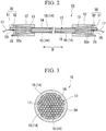
- a cable according to an embodiment of the present invention will be explained with reference to Fig. 1 to 4 .
- Fig. 2 and Fig. 4 some of the wires 14 to be described below will be omitted from the illustration in order to make the drawings easier to see.
- the cable 10 is used in a structure 1, and both ends of the cable 10 are separately affixed to a structure or a foundation.
- the cable 10 moors a float 2 (in the illustrated example, a floating power generation device), which is a structure, to an underwater bottom, not illustrated, which serves as a foundation.
- the cable 10 has one end affixed to the float 2 and the other end affixed to the underwater bottom. Tension is applied to this cable 10 when the float 2 is displaced on the water, so that the float 2, which is the structure, and the underwater bottom, which is the foundation, is displaced with respect to each other.
- the cable 10 comprises a cable body 11, a pair of sockets 12 and a filler material 13.
- the cable body 11 is formed from a plurality of wires 14 that are integrally bundled. The outer diameters of the plurality of wires 14 are equal to each other.
- the cable body 11 is an assembly (strand) comprising the plurality of wires 14. In the present embodiment, the cable body 11 is of the parallel wire strand (PWS) type.
- the cable body 11 comprises, as the plurality of wires 14, steel wires 15 and a fiber-containing wire 16.
- a single fiber-containing wire 16 is provided.
- the fiber-containing wire 16 is disposed on the central axis of the cable body 11, and extends straight along the cable length direction D (see Fig. 2 ), which is the direction of this central axis.
- the steel wires 15 are long, thin wires having a circular transverse cross section.
- the fiber-containing wire 16 comprises an optical fiber 17 (optical transmission path) that extends in the cable length direction D, and a protective tube 18.
- the optical fiber 17 is inserted into the protective tube 18.
- the optical fiber 17 is formed by covering, with a covering film, a fiber body having a core and a cladding.
- the protective tube 18 forms the outer shell of the fiber-containing wire 16, and protects the optical fiber 17 inserted thereinside.
- a central portion that is positioned between the end portions in the cable length direction D is covered by a tubular covering layer 24.
- the plurality of wires 14 is bundled so as to be approximately parallel.
- the end portions of the cable body 11 in the cable length direction D are exposed from the covering layer 24. At these end portions, the plurality of wires 14 is untwisted.
- the sockets 12 are separately affixed (anchored) to the aforementioned structure or the aforementioned foundation.
- the sockets 12 may be affixed to the structure or the foundation by employing, for example, a pin anchoring method, a method making use of bearing pressure, or the like.
- Both end portions of the cable body 11 are separately inserted through sockets 12.
- the respective end portions of the plurality of wires 14 that are untwisted are disposed inside the sockets 12.
- a filler material 13 attaches the end portions of the cable body 11 with the sockets 12.
- the filler material 13 fills the insides of the sockets 12, and in the illustrated example, fills a space, inside a socket 12, located to the inside of an anchoring plate 25, in the cable length direction D.
- the filler material 13 is formed, for example, by casting an alloy or a synthetic resin.
- the tube end portion of the protective tube 18 is attached to the filler material 13.
- the anchoring plate 25 is provided so as to cover the filler material 13 from the outside in the cable length direction D.
- the anchoring plate 25 may be formed from a metal-based material, a resin-based material, a rubber-based material or the like.
- the anchoring plate 25 is formed in the shape of a disc, and is provided in a state free from the inner circumferential surface of the socket 12. In other words, a force that is applied to the anchoring plate 25 inward in the cable length direction D will be directly transmitted to the filler material 13, and will be transmitted to the socket 12 through the filler material 13.
- the fiber-containing wire 16 is attached to the filler material 13, and the optical fiber 17 is exposed from an end portion 26 of the protective tube 18 that is exposed from the anchoring plate 25 to the outside.
- the end portion 26 is affixed to the anchoring plate 25.
- the optical fiber 17 that is exposed form the end portion 26 of the protective tube 18 is passed through an aperture portion 27 (see Fig. 4 ) in the end portion 26, and protrudes further outside, in the cable length direction D, than the socket 12.
- the aperture portion 27 has an inner diameter that is greater than the outer diameter of the optical fiber 17, and the optical fiber 17 is able to move along the axial direction thereof with respect to the anchoring plate 25.
- the optical fiber 17 that protrudes from the anchoring plate 25 to the outside in the cable length direction D is wound about a spool 30 (tensile strain-imparting portion), then guided out in an arbitrary direction.
- the spool 30 has a disc-shaped spool body 31 (spool portion) and a base portion 32 that rotatably supports the spool body 31.
- the spool body 31 is formed so that the outer circumferential surface thereof is a circular circumferential surface over which the optical fiber 17 can slide in the circumferential direction.
- the optical fiber 17 is wound in a groove portion 31m formed in the outer circumferential surface of the spool body 31.
- the spool body 31 is arranged so that a point 31s in the circumferential direction of the outer circumferential portion thereof intersects with (is tangential with) a line of extension from the aperture portion 27. In other words, the optical fiber 17 which passes through and protrudes from the aperture portion 27 is wound about the spool body 31 from a tangential direction.
- the rotation of the spool body 31 can be restricted by an appropriate rotation restriction means which is not illustrated.
- the optical fiber 17 is affixed to the spool body 31 by means of the frictional force generated with respect to the groove portion 31m, and fixing means, not illustrated, for fixing the optical fiber 17 to the spool body 31.
- the optical fiber 17 may be wound about the spool body 31 multiple times (for example, two or three times). Additionally, if sufficient frictional force can be secured, then the optical fiber 17 may be draped over the spool body 31 and only wound by about one-half circuit around the spool body 31.
- the fixing means it is possible to use a friction plate that generates friction between the groove portion 31m and the optical fiber 17, or a self-adhesive tape, an adhesive agent or the like that affixes the optical fiber 17 to the spool body 31.
- These fixing means are preferably attached with a strength that allows for removal from the spool body 31, so that the optical fiber 17 can be easily released from fixation to the spool body 31 when the optical fiber 17 is to be replaced.
- One end 32a of the base portion 32 is affixed to the anchoring plate 25.
- the spool 30 is held in the socket 12 by the anchoring plate 25 and the filler material 13, so that when the cable body 11 expands or contracts, the spool 30 moves integrally with the filler material 13.
- the spool body 31 is constrained by a rotation restricting means (not illustrated).
- the measurement device it is possible to employ, for example, a structure that detects the strain distribution in the optical fiber 17 by inputting light into the optical fiber 17 and detecting the reflected light, and that uses the strain distribution to determine the tension applied to the cable body 11.
- the strain can be accurately measured by applying an initial tensile strain that is at least an appropriate amount higher than the tensile strain to be measured.
- the cable 10 is provided with a temperature-measuring optical fiber (not illustrated) in addition to the above-mentioned optical fiber 17. Since the strain detection in the above-mentioned optical fiber 17 is temperature-dependent, an optical fiber of the same type as the strain-detecting optical fiber 17 is provided for the purpose of measuring the temperature, and accuracy is ensured by using this optical fiber to correct for temperature. In the temperature-measuring optical fiber, the temperature is accurately measured by not applying tension and providing slack so as not to be affected by the tension variations in the cable 10.
- the optical fiber 17 protrudes from the protective tube 18, in the cable length direction D, further outside than the socket 12, and a spool 30 that removably holds the optical fiber 17 and imparts an initial tensile strain to the optical fiber 17 is provided.
- the optical fiber 17 can be made to expand and contract integrally with the cable body 11 when tension is applied to the cable body 11.
- the optical fiber 17 can be precisely strained by the tension applied to the cable body 11. Therefore, the tension applied to the cable body 11 can be measured with high accuracy on the basis of the change in the strain on the optical fiber 17.
- the optical fiber 17 can be withdrawn from the protective tube 18, and removed from the cable 10. As a result, the optical fiber 17 can be conveniently replaced when the optical fiber 17 has been damaged or the like.
- the spool 30 comprises a spool body 31 that holds the optical fiber 17 by winding the optical fiber 17 around a groove portion 31m.
- the optical fiber 17 can be easily held by the frictional force generated between optical fiber 17 and the groove portion m of the spool body 31. Therefore, in the case of a cable 10 comprising fixing means for fixing the optical fiber 17 in addition to the spool body 31, as in the present embodiment, the anchoring force applied to the optical fiber 17 by the fixing means can be held low. As a result, when tension is applied to the cable body 11, the stress generated in a fixed portion of the optical fiber 17 fixed to the fixing means can be made small, and the fixed portion can be made less susceptible to fatigue fracture or brittle fracture.
- the hold on the optical fiber 17 can be easily released by unwinding, from the spool body 31, the optical fiber 17 that has been wound about the spool body 31. As a result, the optical fiber 17 can be conveniently replaced when the optical fiber 17 has been damaged or the like.
- the groove portion 31m of the spool body is formed so as to have a circular circumferential surface over which the optical fiber 17 can slide in the circumferential direction. Due to the groove portion 31m of the spool body 31 being a circular circumferential surface, the frictional force generated with respect to the spool body 31 by the optical fiber 17 which is wound about the spool body 31 from a tangential direction gradually increases in advancing along the circumferential direction from the tangent position. Thus, when a force acts on the optical fiber 17 in the tensile direction, localized stresses will not tend to occur in the optical fiber 17. As a result, it is possible to suppress damage or breakage of the optical fiber 17.
- the spool body 31 is formed so as to be able to rotate in the circumferential direction, and comprises rotation restriction means for restricting rotation in the circumferential direction.
- an initial tensile strain can be introduced to the optical fiber 17 by rotating the spool body 31.
- the state of introduction of the initial tensile strain to the optical fiber 17 can be maintained by restricting the rotation of the spool body 31 by the rotation restriction means.
- the work required for introducing and adjusting the initial tensile strain in the optical fiber 17 can be easily performed.
- the spool 30 is held on the socket 12 by the filler material 13.
- the spool 30 when tension is applied to the cable body 11, the spool 30 will be displaced, along with the filler material 13, integrally with the end portion of the cable body 11.
- the displacement of the spool 30 will be restricted by the socket 12 when tension is applied to the cable body 11, so the optical fiber 17 will be subjected to tension variations due to relative displacement with respect to the spool 30 in addition to the tension variations in the cable body 11.
- the application, to the optical fiber 17, of components other than the tension variations in the cable body 11 can be suppressed by directly holding the spool 30 by the filler material 13 rather than the socket 12.
- the tension applied to the cable body 11 can be measured with high accuracy on the basis of the strain in the optical fiber 17.
- the optical fiber 17 that has been passed through the protective tube 18 can be held by the spool 30 to impart an initial tensile strain.
- the introduction of an initial tensile strain to the optical fiber 17 can be easily implemented, for example, during installation work for the cable 10, or during replacement work for the optical fiber 17 in an installed cable 10. Therefore, it is possible to improve the work efficiency when installing the cable 10 or replacing the optical fiber 17, and the work efficiency during calibration for detection of cable tension or the like.
- the present invention is not limited thereto.
- two or more of the plurality of wires 14 may be fiber-containing wires 16.
- a plurality of optical fibers may be inserted into a fiber-containing wire 16, and the plurality of optical fibers may be optical fibers that detect two or more different types of information.
- one may be a temperature-measuring optical fiber, and the other may be a strain-measuring optical fiber.
- the plurality of optical fibers may be wound around a single spool 30, or may be wound around separately provided spools 30.
- the anchoring plate 25 may be absent. In that case, the spool 30 may be directly attached to the filler material 13.
- the measurement device may be configured so as to be capable of detecting two or more different types of information. For example, it may be configured to be able to detect both temperature and strain information.
- the arrangement of the optical fiber 17 in the cable body 11 is not limited so as to be arranged on a concentric circle as indicated in the above-mentioned embodiment, and it is sufficient for at least one optical fiber 17 to be provided in the cable 10. Additionally, the structures of the optical fiber 17 and the fiber-containing wire 16, the principles of the measurement method and the like are not limited to those indicated in the above description, and various types can be applied.
- the structure of the cable 10 is not limited to that of a parallel wire strand as explained in the above-described embodiments.
- the steel wires 15 and the fiber-containing wire 16 forming the cable body 11 may be twisted together.
- the structure may be a multi-stranded structure, i.e. one wherein a plurality of cable bodies 11 as indicated in the embodiments or a plurality of cable bodies 11 formed by twisting together steel wires 15 and a fiber-containing wire 16 are further bundled to form a single cable.
- a cable body 11 it is also possible to employ a structure wherein all or a part of the steel wire 15 is replaced with a wire formed from a fiber material (e.g., a carbon fiber or the like).
- the optical fiber 17 is simply inserted into the protective tube 18 and can be replaced, but the present invention is not limited thereto.
- the optical fiber 17 may be irremovably fixed to the protective tube 18 by holding the optical fiber 17 by means of the spool 30 to introduce an initial strain, then filling the space between the optical fiber 17 and the protective tube 18 with a bonding agent (e.g., a resin material or the like).
- a bonding agent e.g., a resin material or the like.
- the present invention is not limited to a cable 10 that is used to moor a float 2.
- it may be a cable 10 for use in a suspension structure in a suspended roof structure in an architectural structure, or may be applied to a cable 10 used for a bridge such as a cable-stayed bridge, a suspension bridge or the like.
- bridges include those that are laid across rivers, straits, roads and the like.
Landscapes
- Physics & Mathematics (AREA)
- General Physics & Mathematics (AREA)
- Optics & Photonics (AREA)
- Engineering & Computer Science (AREA)
- Architecture (AREA)
- Civil Engineering (AREA)
- Structural Engineering (AREA)
- Optical Transform (AREA)
- Light Guides In General And Applications Therefor (AREA)
- Optical Fibers, Optical Fiber Cores, And Optical Fiber Bundles (AREA)
- Force Measurement Appropriate To Specific Purposes (AREA)
Applications Claiming Priority (2)
| Application Number | Priority Date | Filing Date | Title |
|---|---|---|---|
| JP2015168268A JP5879453B1 (ja) | 2015-08-27 | 2015-08-27 | ケーブル及び光ファイバへの初期引張歪の導入方法 |
| PCT/JP2016/062611 WO2017033494A1 (fr) | 2015-08-27 | 2016-04-21 | Câble et procédé d'introduction d'une déformation en traction initiale dans une fibre optique |
Publications (2)
| Publication Number | Publication Date |
|---|---|
| EP3343183A1 true EP3343183A1 (fr) | 2018-07-04 |
| EP3343183A4 EP3343183A4 (fr) | 2019-04-17 |
Family
ID=55440645
Family Applications (1)
| Application Number | Title | Priority Date | Filing Date |
|---|---|---|---|
| EP16838841.1A Withdrawn EP3343183A4 (fr) | 2015-08-27 | 2016-04-21 | Câble et procédé d'introduction d'une déformation en traction initiale dans une fibre optique |
Country Status (5)
| Country | Link |
|---|---|
| US (1) | US9958299B2 (fr) |
| EP (1) | EP3343183A4 (fr) |
| JP (1) | JP5879453B1 (fr) |
| CN (1) | CN107076585B (fr) |
| WO (1) | WO2017033494A1 (fr) |
Cited By (2)
| Publication number | Priority date | Publication date | Assignee | Title |
|---|---|---|---|---|
| CN109916550A (zh) * | 2019-03-29 | 2019-06-21 | 重庆交通大学 | 基于超声导波能量熵谱的钢绞线张拉力检测方法 |
| EP4309991A1 (fr) * | 2022-07-22 | 2024-01-24 | TechnipFMC Subsea France | Structure d'amarrage en mer destinée à raccorder un ensemble de surface à un ancrage sous-marin et installation en mer associée |
Families Citing this family (8)
| Publication number | Priority date | Publication date | Assignee | Title |
|---|---|---|---|---|
| JP5879453B1 (ja) * | 2015-08-27 | 2016-03-08 | 新日鉄住金エンジニアリング株式会社 | ケーブル及び光ファイバへの初期引張歪の導入方法 |
| CN105928646B (zh) * | 2016-07-15 | 2018-07-24 | 重庆交通大学 | 基于光纤分布式测量的斜拉索锚头性能衰退状态监测方法 |
| CN109083022B (zh) * | 2018-09-30 | 2023-05-23 | 柳州欧维姆结构检测技术有限公司 | 平行钢绞线斜拉索施工索力均匀性监测系统及施工方法 |
| EP3889028B1 (fr) * | 2018-11-26 | 2023-06-07 | Teijin Limited | Système de surveillance de ligne d'amarrage, système de gestion d'amarrage, procédé de surveillance de ligne d'amarrage et procédé de gestion d'amarrage |
| DK3969866T3 (en) * | 2019-05-12 | 2026-03-16 | Hampidjan Hf | A process for ascertaining the elongation of a load-bearing cable |
| CN110685221A (zh) * | 2019-09-29 | 2020-01-14 | 同济大学 | 一种含有外包橡胶光纤的智能拉索及其制作方法 |
| CN112880635A (zh) * | 2021-01-15 | 2021-06-01 | 中山大学 | 一种地基层水平向流变监测装置及监测方法 |
| JP7734803B1 (ja) * | 2024-07-23 | 2025-09-05 | 日鉄エンジニアリング株式会社 | パラレルワイヤーの配置方法 |
Family Cites Families (27)
| Publication number | Priority date | Publication date | Assignee | Title |
|---|---|---|---|---|
| JPH03124889A (ja) * | 1989-10-06 | 1991-05-28 | Nippon Steel Corp | 光ファイバの組込み可能なケーブル |
| US5182779A (en) * | 1990-04-05 | 1993-01-26 | Ltv Aerospace And Defense Company | Device, system and process for detecting tensile loads on a rope having an optical fiber incorporated therein |
| JPH0587007U (ja) | 1992-04-27 | 1993-11-22 | 日立造船株式会社 | ケーブルの温度測定装置 |
| JP2001296190A (ja) * | 2000-04-14 | 2001-10-26 | Foundation Of River & Basin Integrated Communications Japan | 歪センサ用光ファイバケーブル及びその敷設方法 |
| AU2001264909A1 (en) * | 2000-07-11 | 2002-01-21 | Corning Incorporated | Variable tension fiber winding |
| FR2823299B1 (fr) * | 2001-04-04 | 2003-09-19 | Commissariat Energie Atomique | Extensometre a longue base, a fibre optique tendue et reseau de bragg, et procede de fabrication de cet extensometre |
| KR20020082414A (ko) * | 2001-04-20 | 2002-10-31 | 후루까와덴끼고오교 가부시끼가이샤 | 케이블보호관 및 그 관로부설방법 및 도입방법 |
| US6554217B1 (en) * | 2001-08-31 | 2003-04-29 | Stocker Yale, Inc. | Fiber optic cable winding tool |
| JP2004184759A (ja) * | 2002-12-04 | 2004-07-02 | Occ Corp | 光ファイバ引留め装置 |
| US6873893B1 (en) * | 2003-08-01 | 2005-03-29 | The United States Of America As Represented By The Secretary Of The Navy | Missile warning and protection system for aircraft platforms |
| CN100342076C (zh) * | 2003-09-03 | 2007-10-10 | 欧进萍 | 光纤光栅智能拉索 |
| EP1709416B1 (fr) * | 2004-01-23 | 2018-03-07 | LM Wind Power International Technology II ApS | Dispositif comprenant un systeme concu pour etre utilise dans la compensation thermique de mesures de contrainte dans des structures renforcees par des fibres |
| JP2006250647A (ja) * | 2005-03-09 | 2006-09-21 | Jfe Koken Corp | ワイヤケーブル、並びに張力測定システム及び張力測定方法 |
| JP2007297777A (ja) * | 2006-04-27 | 2007-11-15 | Nippon Steel Engineering Co Ltd | 吊り構造用のケーブル及び測定システム |
| US8090234B2 (en) | 2008-04-21 | 2012-01-03 | Adc Telecommunications, Inc. | Cable anchoring device |
| JP5604760B2 (ja) * | 2008-12-05 | 2014-10-15 | 住友電工スチールワイヤー株式会社 | 緊張部材 |
| NL2002743C2 (nl) | 2009-04-10 | 2010-10-12 | Stichting Energie | Inrichting en werkwijze voor het meten van rek. |
| CN101701450B (zh) * | 2009-09-30 | 2011-12-21 | 法尔胜集团公司 | 内置光纤光栅传感器的桥梁用智能缆索系统 |
| CN201610523U (zh) * | 2010-02-08 | 2010-10-20 | 法尔胜集团有限公司 | 缆索内置光纤光栅应变传感器与索内钢丝的机械连接结构 |
| CN202039295U (zh) * | 2011-04-06 | 2011-11-16 | 江苏法尔胜新日制铁缆索有限公司 | 耐超高疲劳应力幅的钢索 |
| IL215002A (en) * | 2011-09-06 | 2013-02-28 | Elbit Systems Ltd | Hf antenna assembly |
| WO2013052543A2 (fr) | 2011-10-03 | 2013-04-11 | Afl Telecommunications Llc | Câble de détection |
| JP5769676B2 (ja) | 2012-08-17 | 2015-08-26 | 公益財団法人地球環境産業技術研究機構 | 物質の圧力、温度、ひずみ分布測定システム、これを用いた二酸化炭素地中貯留の監視方法、二酸化炭素注入による地層安定性への影響評価方法、および結氷監視方法 |
| TWI510720B (zh) | 2013-06-19 | 2015-12-01 | Jinn Her Entpr Co Ltd | 可同步預拉緊光纖光柵與螺栓的感測螺絲裝置 |
| US9680279B2 (en) * | 2014-09-10 | 2017-06-13 | Bae Systems Information And Electronic Systems Integration Inc. | Ruggedized fiber optic laser for high stress environments |
| JP6293035B2 (ja) | 2014-10-22 | 2018-03-14 | 新日鉄住金エンジニアリング株式会社 | ケーブル |
| JP5879453B1 (ja) * | 2015-08-27 | 2016-03-08 | 新日鉄住金エンジニアリング株式会社 | ケーブル及び光ファイバへの初期引張歪の導入方法 |
-
2015
- 2015-08-27 JP JP2015168268A patent/JP5879453B1/ja active Active
-
2016
- 2016-04-21 EP EP16838841.1A patent/EP3343183A4/fr not_active Withdrawn
- 2016-04-21 WO PCT/JP2016/062611 patent/WO2017033494A1/fr not_active Ceased
- 2016-04-21 US US15/522,192 patent/US9958299B2/en active Active
- 2016-04-21 CN CN201680003346.4A patent/CN107076585B/zh active Active
Cited By (3)
| Publication number | Priority date | Publication date | Assignee | Title |
|---|---|---|---|---|
| CN109916550A (zh) * | 2019-03-29 | 2019-06-21 | 重庆交通大学 | 基于超声导波能量熵谱的钢绞线张拉力检测方法 |
| EP4309991A1 (fr) * | 2022-07-22 | 2024-01-24 | TechnipFMC Subsea France | Structure d'amarrage en mer destinée à raccorder un ensemble de surface à un ancrage sous-marin et installation en mer associée |
| WO2024018068A1 (fr) * | 2022-07-22 | 2024-01-25 | Technipfmc Subsea France | Structure d'amarrage en mer destinée à relier un ensemble de surface à un ancrage sous-marin, et installation en mer associée |
Also Published As
| Publication number | Publication date |
|---|---|
| US20170328743A1 (en) | 2017-11-16 |
| CN107076585A (zh) | 2017-08-18 |
| US9958299B2 (en) | 2018-05-01 |
| CN107076585B (zh) | 2020-03-13 |
| EP3343183A4 (fr) | 2019-04-17 |
| JP5879453B1 (ja) | 2016-03-08 |
| WO2017033494A1 (fr) | 2017-03-02 |
| JP2017044925A (ja) | 2017-03-02 |
Similar Documents
| Publication | Publication Date | Title |
|---|---|---|
| US9958299B2 (en) | Cable and method for introducing initial tensile strain to optical fiber | |
| CN103438815B (zh) | 一种高耐久长标距光纤光栅传感器及其制造方法 | |
| CN107076624B (zh) | 缆线 | |
| CN105300305B (zh) | 耦合光纤光栅的大量程智能高强钢丝及其制作方法 | |
| JP5604760B2 (ja) | 緊張部材 | |
| GB2401940A (en) | Fibre optical cable for monitoring temperature and strain | |
| CN101787676A (zh) | 缆索内置光纤光栅应变传感器的安装方法 | |
| US20220206238A1 (en) | Multisensing Optical Fiber Cable | |
| CN104199159A (zh) | 同时监测温度和应变的扁平型带状传感光缆 | |
| CN101846565B (zh) | 基于缆索锚固区植入应变传感器实现索力在线测量的方法 | |
| CN202720372U (zh) | 紧套光纤光栅串传感光缆 | |
| CN204101777U (zh) | 同时监测温度和应变的扁平型带状传感光缆 | |
| CN207248706U (zh) | 一种基于光纤传感的预应力锚索腐蚀损伤监测装置 | |
| EP3502759B1 (fr) | Dispositif et procédé d'inspection d'unité de fibre optique | |
| CN110847038A (zh) | 一种自感知平行钢丝拉索及其制作方法 | |
| JP2001124529A (ja) | 光ファイバ利用歪、変位センサ | |
| JP2019127794A (ja) | アンカーテンドンおよびグラウンドアンカーの施工方法 | |
| JP2008298672A (ja) | 歪みセンシング用光ケーブル | |
| KR100339978B1 (ko) | 광변형센서 | |
| JP2670377B2 (ja) | 多心光ファイバの同径接続方法 | |
| CN115219082B (zh) | 一种基于光纤光栅的温度自补偿全方位径向压力感知缆 | |
| KR100301775B1 (ko) | 광변형센서 | |
| CN109931875A (zh) | 一种掩埋式岩土工程监测装置 | |
| CN117822336A (zh) | 一种接力式大应变监测用钢绞线及其制造、使用方法 | |
| RU122784U1 (ru) | Оптический кабель |
Legal Events
| Date | Code | Title | Description |
|---|---|---|---|
| PUAI | Public reference made under article 153(3) epc to a published international application that has entered the european phase |
Free format text: ORIGINAL CODE: 0009012 |
|
| 17P | Request for examination filed |
Effective date: 20170529 |
|
| AK | Designated contracting states |
Kind code of ref document: A1 Designated state(s): AL AT BE BG CH CY CZ DE DK EE ES FI FR GB GR HR HU IE IS IT LI LT LU LV MC MK MT NL NO PL PT RO RS SE SI SK SM TR |
|
| AX | Request for extension of the european patent |
Extension state: BA ME |
|
| DAV | Request for validation of the european patent (deleted) | ||
| DAX | Request for extension of the european patent (deleted) | ||
| A4 | Supplementary search report drawn up and despatched |
Effective date: 20190319 |
|
| RIC1 | Information provided on ipc code assigned before grant |
Ipc: G01D 5/353 20060101AFI20190313BHEP Ipc: G01B 11/16 20060101ALI20190313BHEP Ipc: G01L 5/04 20060101ALI20190313BHEP Ipc: G02B 6/44 20060101ALI20190313BHEP Ipc: G01L 1/24 20060101ALI20190313BHEP Ipc: E01D 19/16 20060101ALI20190313BHEP |
|
| GRAP | Despatch of communication of intention to grant a patent |
Free format text: ORIGINAL CODE: EPIDOSNIGR1 |
|
| INTG | Intention to grant announced |
Effective date: 20191114 |
|
| STAA | Information on the status of an ep patent application or granted ep patent |
Free format text: STATUS: THE APPLICATION IS DEEMED TO BE WITHDRAWN |
|
| 18D | Application deemed to be withdrawn |
Effective date: 20200603 |