EP3343701A1 - Gruppenantenne und strahlausrichtungsverfahren für gruppenantenne - Google Patents
Gruppenantenne und strahlausrichtungsverfahren für gruppenantenne Download PDFInfo
- Publication number
- EP3343701A1 EP3343701A1 EP15905036.8A EP15905036A EP3343701A1 EP 3343701 A1 EP3343701 A1 EP 3343701A1 EP 15905036 A EP15905036 A EP 15905036A EP 3343701 A1 EP3343701 A1 EP 3343701A1
- Authority
- EP
- European Patent Office
- Prior art keywords
- subarray
- power
- output signal
- array antenna
- alignment direction
- Prior art date
- Legal status (The legal status is an assumption and is not a legal conclusion. Google has not performed a legal analysis and makes no representation as to the accuracy of the status listed.)
- Granted
Links
Images


Classifications
-
- H—ELECTRICITY
- H01—ELECTRIC ELEMENTS
- H01Q—ANTENNAS, i.e. RADIO AERIALS
- H01Q3/00—Arrangements for changing or varying the orientation or the shape of the directional pattern of the waves radiated from an antenna or antenna system
- H01Q3/26—Arrangements for changing or varying the orientation or the shape of the directional pattern of the waves radiated from an antenna or antenna system varying the relative phase or relative amplitude of energisation between two or more active radiating elements; varying the distribution of energy across a radiating aperture
- H01Q3/30—Arrangements for changing or varying the orientation or the shape of the directional pattern of the waves radiated from an antenna or antenna system varying the relative phase or relative amplitude of energisation between two or more active radiating elements; varying the distribution of energy across a radiating aperture varying the relative phase between the radiating elements of an array
- H01Q3/34—Arrangements for changing or varying the orientation or the shape of the directional pattern of the waves radiated from an antenna or antenna system varying the relative phase or relative amplitude of energisation between two or more active radiating elements; varying the distribution of energy across a radiating aperture varying the relative phase between the radiating elements of an array by electrical means
- H01Q3/36—Arrangements for changing or varying the orientation or the shape of the directional pattern of the waves radiated from an antenna or antenna system varying the relative phase or relative amplitude of energisation between two or more active radiating elements; varying the distribution of energy across a radiating aperture varying the relative phase between the radiating elements of an array by electrical means with variable phase-shifters
-
- H—ELECTRICITY
- H01—ELECTRIC ELEMENTS
- H01Q—ANTENNAS, i.e. RADIO AERIALS
- H01Q1/00—Details of, or arrangements associated with, antennas
- H01Q1/12—Supports; Mounting means
- H01Q1/22—Supports; Mounting means by structural association with other equipment or articles
- H01Q1/24—Supports; Mounting means by structural association with other equipment or articles with receiving set
-
- H—ELECTRICITY
- H01—ELECTRIC ELEMENTS
- H01Q—ANTENNAS, i.e. RADIO AERIALS
- H01Q21/00—Antenna arrays or systems
- H01Q21/06—Arrays of individually energised antenna units similarly polarised and spaced apart
-
- H—ELECTRICITY
- H01—ELECTRIC ELEMENTS
- H01Q—ANTENNAS, i.e. RADIO AERIALS
- H01Q25/00—Antennas or antenna systems providing at least two radiating patterns
Definitions
- Embodiments of the present invention relate to the field of communications technologies, and in particular, to an array antenna and a beam alignment method for an array antenna.
- each array element of the array antenna is equipped with a corresponding phase shifter that changes a signal phase, and the phase shifter is generally controlled by using an electrical signal.
- the array element converts the microwave signal into an electrical signal
- the phase shifter performs phase shifting on the electrical signal from the array element and sends the phase-shifted electrical signal to a combiner for combination.
- a receiving beam direction corresponding to a combined signal may be changed by changing a phase configuration of the phase shifter.
- Embodiments of the present invention provide an array antenna and a beam alignment method for an array antenna, so as to quickly implement array antenna alignment.
- an array antenna including a first subarray, a second subarray, a first power detector, a second power detector, and a decision device, where the first power detector is connected to the first subarray, the second power detector is connected to the second subarray, the decision device is connected to the first power detector, the decision device is connected to the second power detector, the first power detector is configured to detect a power of an output signal of the first subarray, the second power detector is configured to detect a power of an output signal of the second subarray, and the decision device is configured to determine a first alignment direction of the array antenna according to the power of the output signal of the first subarray and the power of the output signal of the second subarray.
- the array antenna further includes a third subarray and a third power detector, where the third power detector is connected to the third subarray, the decision device is connected to the third power detector, the third power detector is configured to detect a power of an output signal of the third subarray, and the decision device is specifically configured to determine the first alignment direction of the array antenna according to the power of the output signal of the first subarray, the power of the output signal of the second subarray, and the power of the output signal of the third subarray.
- the array antenna further includes a fourth subarray and a fourth power detector, where the fourth power detector is connected to the fourth subarray, the decision device is connected to the fourth power detector, the fourth power detector is configured to detect a power of an output signal of the fourth subarray, and the decision device is specifically configured to determine the first alignment direction of the array antenna according to the power of the output signal of the first subarray, the power of the output signal of the second subarray, the power of the output signal of the third subarray, and the power of the output signal of the fourth subarray.
- the array antenna further includes (N-2) subarrays and (N-2) power detectors, where N is an integer greater than 2, each power detector is connected to a corresponding subarray and is configured to detect a power of an output signal of the corresponding subarray, the decision device is further connected to the (N-2) power detectors, and the decision device is specifically configured to determine the first alignment direction of the array antenna according to the power of the output signal of the first subarray, the power of the output signal of the second subarray, and powers of output signals of the (N-2) subarrays.
- the decision device is specifically configured to determine the first alignment direction of the array antenna according to a power of the output signal of the first subarray at a first moment and a power of the output signal of the second subarray at the first moment.
- the first subarray includes a first array element, a second array element, a first phase shifter, a second phase shifter, and a first subarray combiner, where the first phase shifter is connected to the first array element, the second phase shifter is connected to the second array element, the first subarray combiner is connected to the first phase shifter, the first subarray combiner is connected to the second phase shifter, the first phase shifter is configured to perform phase shifting on a signal from the first array element and send the signal to the first subarray combiner, the second phase shifter is configured to perform phase shifting on a signal from the second array element and send the signal to the first subarray combiner, and the first subarray combiner is configured to combine the signal from the first phase shifter and the signal from the second phase shifter, and output a signal.
- the array antenna further includes an array antenna combiner, where the array antenna combiner is connected to the first subarray, the array antenna combiner is connected to the second subarray, and the array antenna combiner is configured to combine a signal from the first subarray and a signal from the second subarray.
- the first power detector is specifically configured to detect a power of a coupling signal of the signal sent by the first subarray to the array antenna combiner
- the second power detector is specifically configured to detect a power of a coupling signal of the signal sent by the second subarray to the array antenna combiner.
- a beam alignment method for an array antenna includes at least a first subarray and a second subarray, and the method includes:
- the determining a first alignment direction of the array antenna according to the power of the output signal of the first subarray and the power of the output signal of the second subarray specifically includes: determining the first alignment direction of the array antenna according to a power of the output signal of the first subarray at a first moment and a power of the output signal of the second subarray at the first moment.
- the method before the setting a receiving beam direction corresponding to an output signal of the first subarray as a first direction, the method further includes:
- an included angle between the first direction and the second alignment direction is the same as an included angle between the second direction and the second alignment direction.
- projection of the first direction on the array antenna and projection of the second direction on the array antenna are in a line.
- the array antenna further includes a third subarray
- the method further includes:
- the array antenna further includes a third subarray and a fourth subarray
- the method further includes:
- the array antenna further includes a fifth subarray
- the method further includes:
- the method before the setting a receiving beam direction corresponding to an output signal of the first subarray as a first direction, the method further includes: determining that a power of the output signal of the array antenna is less than a first threshold; or determining that a timer expires.
- the first subarray and the second subarray have equal receiving areas.
- the determining a first alignment direction of the array antenna according to the power of the output signal of the first subarray and the power of the output signal of the second subarray includes: if the power of the output signal of the first subarray is greater than the power of the output signal of the second subarray, and a power difference is greater than a second threshold, determining that the first alignment direction is the first direction.
- the array antenna provided in the embodiments of the present invention includes at least two subarrays, two power detectors, and one decision device.
- the two power detectors may detect the powers of the output signals of the corresponding subarrays at the same time, and therefore, the decision device may determine the first alignment direction of the array antenna according to the powers of the output signals of the two subarrays.
- the two power detectors detect a same incident signal at a same moment. Therefore, a better receiving beam direction may be directly obtained by means of comparison, and an average power within a period of time does not need to be collected, thereby quickly implementing array alignment.
- FIG. 1 is a schematic structural diagram of an array antenna according to an embodiment of the present invention.
- the array antenna includes a total of N subarrays: a subarray 1, a subarray 2, ..., and a subarray N, a total of M couplers: a coupler 1, a coupler 2, ..., and a coupler M, and a total of M power detectors: a power detector 1, a power detector 2, ..., and a power detector M.
- N and M are integers greater than 1, and N and M may be the same or may be different.
- the array antenna further includes a combiner 101 and a decision device 102.
- the combiner 101 is connected to the N subarrays, and may be connected to M subarrays of the N subarrays by using the M couplers, the decision device 102 is connected to the M power detectors, and the M power detectors are connected to the M couplers respectively.
- receiving beam directions corresponding to output signals of the N subarrays may be set as a same direction, for example, all are set as a first alignment direction.
- the combiner 101 receives and combines the output signals of the N subarrays, and after combining, a receiving beam direction corresponding to an output signal of the combiner 101 is the first alignment direction.
- processing such as frequency conversion and analog-to-digital conversion may be performed on the receiving signal obtained after the combiner 101 performs combination.
- the M coupler may not operate, that is, no energy is coupled to the power detectors, and all energy is sent to the combiner 101; or the M couplers may operate, that is, some energy is coupled to the power detectors for monitoring.
- the receiving beam direction corresponding to the output signal obtained after the combiner 101 performs combination may be set as the first alignment direction, and a receiving beam direction corresponding to an output signal of each subarray does not need to be considered.
- receiving beam directions corresponding to output signals of the M subarrays corresponding to the M coupler need to be set as different directions, or certainly, receiving beam directions corresponding to output signals of some subarrays of the M subarrays may be set as a same direction. In this case, a subarray other than the M subarrays may be set to an original alignment direction and continues to operate. If differences between receiving signal beam directions of the M subarrays and the first alignment direction are not large, the output signal of the combiner 101 is not greatly affected.
- the M power detectors detect powers of the output signals of the M subarrays, and the decision device determines, according to the powers of the output signals of the M subarrays, which receiving beam direction should be selected for performing receiving, that is, obtains an optimized alignment direction of the array antenna. If the optimized alignment direction is different from the original first alignment direction, the optimized alignment direction may be used at a next communication stage to receive a signal.
- the array antenna may include only some components in FIG. 1 .
- the array antenna includes two subarrays, two power detectors, and one decision device.
- Another component and a connection relationship in this embodiment of the present invention are only for ease of description and for ease of understanding of the solution, and may be implemented in another manner or may not be implemented. This is not limited in this embodiment of the present invention.
- the array antenna may include a first subarray, a second subarray, a first power detector, a second power detector, and a decision device.
- the first power detector is connected to the first subarray
- the second power detector is connected to the second subarray
- the decision device is connected to the first power detector
- the decision device is connected to the second power detector
- the first power detector is configured to detect a power of an output signal of the first subarray
- the second power detector is configured to detect a power of an output signal of the second subarray
- the decision device is configured to determine a first alignment direction of the array antenna according to the power of the output signal of the first subarray and the power of the output signal of the second subarray.
- the array antenna may further include a third subarray and a third power detector.
- the third power detector is connected to the third subarray
- the decision device is connected to the third power detector
- the third power detector is configured to detect a power of an output signal of the third subarray
- the decision device is specifically configured to determine the first alignment direction of the array antenna according to the power of the output signal of the first subarray, the power of the output signal of the second subarray, and the power of the output signal of the third subarray.
- the array antenna may further include a fourth subarray and a fourth power detector.
- the fourth power detector is connected to the fourth subarray
- the decision device is connected to the fourth power detector
- the fourth power detector is configured to detect a power of an output signal of the fourth subarray
- the decision device is specifically configured to determine the first alignment direction of the array antenna according to the power of the output signal of the first subarray, the power of the output signal of the second subarray, the power of the output signal of the third subarray, and the power of the output signal of the fourth subarray.
- the decision device may be specifically configured to determine the first alignment direction of the array antenna according to a power of the output signal of the first subarray at a first moment and a power of the output signal of the second subarray at the first moment.
- the array antenna may further include an array antenna combiner.
- the array antenna combiner is connected to the first subarray, the array antenna combiner is connected to the second subarray, and the array antenna combiner is configured to combine a signal from the first subarray and a signal from the second subarray. If there are a third subarray, a fourth subarray, and the like, the array antenna combiner is further connected to these subarrays, and combines output signals received from these subarrays.
- the first power detector is specifically configured to detect a power of a coupling signal of the signal sent by the first subarray to the array antenna combiner
- the second power detector is specifically configured to detect a power of a coupling signal of the signal sent by the second subarray to the array antenna combiner. That is, signal coupling is performed by using the coupler in FIG. 1 , and the signal is sent to the power detector for power detection; or certainly, power detection may be directly performed on the output signal of the subarray.
- the following uses a subarray structure to describe how to set the receiving beam direction corresponding to the output signal of the subarray.
- the subarray in FIG. 1 may be implemented in a plurality of manners, and two manners are used as examples for description in the following by using FIG. 2 and FIG. 3 .
- FIG. 2 is a schematic structural diagram of a subarray according to an embodiment of the present invention.
- the subarray includes a total of O array elements: an array element 1, an array element 2, ..., and an array element O, a total of O phase shifters: a phase shifter 1, a phase shifter 2, ..., and a phase shifter O, and further includes one subarray combiner 201.
- O is an integer greater than 1.
- the array element is configured to receive a radio signal, for example, a microwave signal, and the array element converts the received microwave signal into an electrical signal.
- the phase shifter performs phase shifting on a phase of a corresponding electrical signal.
- the subarray combiner 201 receives and combines signals from the O phase shifters.
- an output signal obtained after the subarray combiner 201 performs combination is sent to the combiner 101 for subsequent processing.
- Strength of a signal obtained after the subarray combiner performs combination may be changed by setting a parameter of the phase shifter, that is, a receiving beam direction corresponding to an output signal of the subarray may be set.
- 2
- s t ⁇ ⁇ i 1 O w i ⁇ e j i ⁇ 1 ⁇
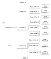
- FIG. 3 is a schematic structural diagram of a subarray according to an embodiment of the present invention.
- the subarray includes Q groups.
- a first group includes a total of P array elements: an array element 11, an array element 12, ..., and an array element 1P, a total of P phase shifters: a phase shifter 11, a phase shifter 12, ..., and a phase shifter 1P, and further includes a combiner 1.
- P and Q are integers greater than 1, each array element is corresponding to one phase shifter, and a signal on which phase shifting is performed is sent to the combiner 1.
- Structures of a second group to a Q th group are the same as the structure of the first group, and are not described herein.
- Signals obtained after the Q combiners perform combination are sent to a subarray combiner 301, and the subarray combiner 301 receives and combines the signals from the Q combiners. If this is applied to the array antenna shown in FIG. 1 , a signal obtained after the subarray combiner 301 performs combination is sent to the combiner 101 for subsequent processing.
- Strength of an output signal of the subarray combiner may be changed by setting a parameter of a phase shifter of each group, that is, a receiving beam direction corresponding to an output signal of the subarray may be set.
- a receiving beam direction corresponding to the output signal obtained after the subarray combiner 301 performs combination may be set by setting the phase shifter of each group.
- the receiving beam direction is set as a first direction.
- a total of P phase shifters: the phase shifter 11, the phase shifter 12, ..., and the phase shifter 1P may be set, to make a beam direction corresponding to a receiving signal obtained after the combiner 1 performs combination be the first direction.
- Phase shifters of other groups are set, to make all beam directions corresponding to receiving signals obtained after a combiner 2 to a combiner Q perform combination be the first direction. In this way, a beam direction corresponding to a receiving signal obtained after the combiner 31 performs combination is also the first direction.
- the PxQ phase shifters may be set on the whole, to make the beam direction corresponding to the receiving signal obtained after the combiner 301 performs combination be the first direction, but a receiving beam direction corresponding to an output signal of a combiner of each group may not be the first direction. This is not limited in the present invention.
- the array antenna is usually installed on a tower, and therefore, a strong wind and another factor may cause a movement of the array antenna. Consequently, a beam direction of a receiving signal needs to be changed so as to improve energy, a signal-to-noise ratio, and the like of the receiving signal.
- the beam direction corresponding to the receiving signal may be monitored and adjusted. The following describes a method for monitoring and adjusting the beam direction corresponding to the receiving signal.
- FIG. 4 is a flowchart of a beam alignment method for an array antenna according to an embodiment of the present invention.
- the array antenna includes at least a first subarray and a second subarray, and the method includes the following steps.
- step S402 the power of the output signal of the first subarray and the power of the output signal of the second subarray may be detected at the same time. Therefore, the power of the output signal of the first subarray and the power of the output signal of the second subarray may be compared at the same time, so as to determine which subarray is corresponding to a better receiving direction. Therefore, in step S403, the first alignment direction of the array antenna may be determined according to a power of the output signal of the first subarray at a first moment and a power of the output signal of the second subarray at the first moment. Because power values of the output signal of the first subarray and the output signal of the second subarray only at a moment need to be compared, a determining speed is quite fast. Certainly, values at more moments may be determined, and weighted averaging may be performed, so as to ensure accuracy of determining the alignment direction.
- this embodiment of the present invention may be applied to monitoring and adjusting of the alignment direction. That is, before S401 is performed, the array antenna has performed normal communication. For example, the array antenna has performed normal receiving in a second alignment direction. However, a strong wind or another factor causes a power reduction of an output signal of a combiner of the array antenna. For example, the power is less than a threshold.
- step S401 may be performed for beam alignment, or a timer may be set to periodically perform step S401, so as to monitor whether a receiving beam direction can be optimized. Certainly, step S401 may be triggered by another trigger condition. This is not limited in this embodiment of the present invention.
- the method may further include: setting the receiving beam direction corresponding to the output signal of the first subarray and the receiving beam direction corresponding to the output signal of the second subarray to a second alignment direction, or setting a receiving beam direction corresponding to an output signal of the array antenna to a second alignment direction.
- the array antenna Before step S401, the array antenna performs normal receiving in the second alignment direction. Therefore, subsequent monitoring and adjusting may be performed based on the second alignment direction.
- the first alignment direction of the array antenna may be determined by comparing only the power of the output signal of the first subarray with the power of the output signal of the second subarray. For example, if the power of the output signal of the first subarray is greater than the power of the output signal of the second subarray, the first direction may be set as the first alignment direction. In a subsequent communication process, the receiving direction corresponding to the output signal of the array antenna is set as the first direction, that is, the first alignment direction.
- step S401 further includes setting a receiving beam direction corresponding to an output signal of a third subarray to a third direction. It may be specified that an included angle between the first direction and the second alignment direction, an included angle between the second direction and the second alignment direction, and an included angle between the third direction and the second alignment direction are the same, and a difference between every adjacent two of projection of the first direction on the array antenna, projection of the second direction on the array antenna, and projection of the third direction on the array antenna is 120 degrees.
- Step S402 further includes detecting a power of the output signal of the third subarray.
- Step S403 specifically includes: determining the first alignment direction of the array antenna according to the power of the output signal of the first subarray, the power of the output signal of the second subarray, and the power of the output signal of the third subarray.
- the first alignment direction of the array antenna may be determined according to the power of the output signal of the first subarray at the first moment, the power of the output signal of the second subarray at the first moment, and a power of the output signal of the third subarray at the first moment.
- step S401 further includes: setting a receiving beam direction corresponding to an output signal of a third subarray to a third direction, and setting a receiving beam direction corresponding to an output signal of a fourth subarray to a fourth direction. It may be specified that an included angle between the first direction and the second alignment direction, an included angle between the second direction and the second alignment direction, an included angle between the third direction and the second alignment direction, and an included angle between the fourth direction and the second alignment direction are the same, and a difference between every adjacent two of projection of the first direction on the array antenna, projection of the second direction on the array antenna, projection of the third direction on the array antenna, and projection of the fourth direction on the array antenna is 90 degrees.
- Step S402 further includes detecting a power of the output signal of the third subarray, and detecting a power of the output signal of the fourth subarray.
- Step S403 specifically includes determining the first alignment direction of the array antenna according to the power of the output signal of the first subarray, the power of the output signal of the second subarray, the power of the output signal of the third subarray, and the power of the output signal of the fourth subarray.
- the first alignment direction of the array antenna may be determined according to the power of the output signal of the first subarray at the first moment, the power of the output signal of the second subarray at the first moment, a power of the output signal of the third subarray at the first moment, and a power of the output signal of the fourth subarray at the first moment.
- step S401 further includes setting a receiving beam direction corresponding to an output signal of a fifth subarray to the second alignment direction.
- Step S402 further includes detecting a power of the output signal of the fifth subarray.
- Step S403 is specifically: determining the first alignment direction of the array antenna according to the power of the output signal of the first subarray at the first moment, the power of the output signal of the second subarray at the first moment, and a power of the output signal of the fifth subarray at the first moment.
- the first alignment direction of the array antenna may be determined according to the power of the output signal of the first subarray at the first moment, the power of the output signal of the second subarray at the first moment, and a power of the output signal of the fifth subarray at the first moment.
- a direction of one of the two subarrays may be set as the second alignment direction.
- the first direction is set as the second alignment direction
- the second direction is changed according to a specified rule, for example, the second direction rotates around the second alignment direction, so as to perform alignment efficiently.
- the first alignment direction of the array antenna needs to be determined according to the power of the output signal of the first subarray and the power of the output signal of the second subarray. If two subarrays are used to monitor and adjust the alignment direction, the first alignment direction may be obtained only according to powers of output signals of the two subarrays. If more subarrays are used to monitor and adjust the alignment direction, the first alignment direction may be obtained according to powers of output signals of the corresponding subarrays. For example, two subarrays are used to monitor and adjust the alignment direction. In this case, for ease of determining the first alignment direction, it may be configured that the first subarray and the second subarray have equal receiving areas.
- the power of the output signal of the first subarray and the power of the output signal of the second subarray may be converted according to the receiving areas, so as to obtain power values based on a same area, and then make a comparison to determine the first alignment direction.
- another algorithm may be used to perform calculation so as to determine the first alignment direction. This is not limited in this embodiment of the present invention.
- the first alignment direction may be determined by using a simple method. For example, when two subarrays are used to monitor and adjust the alignment direction, if the power of the output signal of the first subarray is greater than the power of the output signal of the second subarray, and a power difference is greater than a second threshold, the first alignment direction is the first direction; or if the power of the output signal of the first subarray is greater than the power of the output signal of the second subarray, and a power difference is less than a third threshold, another direction between the first direction and the second direction is calculated according to a specific rule and is used as the first alignment direction. If more than two subarrays are used to monitor and adjust the alignment direction, a similar rule may be used to determine the first alignment direction.
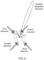
- FIG. 5 and FIG. 6 are used for brief description in the following.
- 16 subarrays are arranged in a 4x4 manner.
- all subarrays form a single receiving beam, that is, a second alignment direction.
- a system determines that a relative displacement occurs between physical devices in the link, and therefore, starts alignment detection to perform beam alignment.
- four 2x2 subarray areas form four independent beams respectively in different directions, and all beams are centered on the second alignment direction at the normal communication moment, and stretch at a fixed offset angle in a "+" shape. That is, included angles between directions of all the beams and the second alignment direction are the same, and projection of all the beams on an array plane is mutually separated at an interval of 90 degrees.
- the four directions are corresponding to a first direction, a second direction, a third direction, and a fourth direction in FIG. 5 .
- Receiving signals are combined in the entire array in a staged combination manner. That is, signal combination is first performed in subarrays in each 2x2 area separately, and reference may be made to the combiner 301 in FIG. 3 . Then, final signal combination is performed on combined signals in the four areas, and reference may be made to the combiner 101 in FIG. 1 .
- During alignment detection four copy signals are respectively coupled from the combined signals in the four areas, and reference may be made to the M couplers in FIG. 1 .
- the four copy signals are sent to four separate power detectors for power detection, and reference may be made to the M power detectors in FIG. 1 .
- Outputs of the power detectors are sent to a decision device for beam alignment direction determining, and reference may be made to the decision device 102 in FIG. 1 .
- the decision device samples outputs of four power detection units at a same moment so as to make a comparison.
- a decision unit may continuously sample detection powers at two or three moments, and select sample values at a moment when the powers are the largest so as to make a comparison. If there is one obvious largest power among four inputs, a beam direction in an area corresponding to the power is used as a first alignment direction for normal communication in a next period, and a phase offset value of an entire transceiver array is updated based on a phase offset value of a phase shifter in the area, so as to change a transceiver beam direction and implement alignment.
- an equal-gain intersection point of beams in these areas may be used as a first alignment direction for normal communication in a next period, and a phase offset value of an entire transceiver array is updated based on an average value of phase offset values of phase shifters in these areas, so as to change a transceiver beam direction and implement alignment.
- all arrays form a single receiving beam, that is, a second alignment direction.
- a communications system periodically allocates an alignment detection timeslot in terms of time.
- the alignment detection timeslot subarrays at four corners form four independent beams respectively in different directions, and all beams are centered on the second alignment direction at the normal communication moment, and stretch at a fixed offset angle in a " ⁇ " shape. That is, included angles between all the beams and B are the same, and projection of all the beams on an array plane is mutually separated at an interval of 90 degrees.
- phase configurations of subarrays in other areas of an array keep unchanged, and the beam direction B is maintained, so as to ensure normal link communication at a detection moment.
- the four directions are corresponding to a first direction, a second direction, a third direction, and a fourth direction in FIG. 6 .
- five copy signals are respectively coupled from four offset beam subarrays and any one of immobile beam subarrays.
- the coupling signals are sent to five separate power detectors for power detection.
- Outputs of the power detectors are sent to a decision device for beam alignment direction determining.
- the decision device samples outputs of five power detection units at a same moment so as to make a comparison.
- a decision unit may continuously sample detection powers at two or three moments, and select sample values at a moment when the powers are the largest so as to make a comparison. If there is one obvious largest power among the five inputs, a beam direction in an area corresponding to the power is used as a first alignment direction for normal communication in a next period, and a phase offset value of an entire transceiver array is updated based on a phase offset value of a phase shifter in the area, so as to change a transceiver beam direction and implement alignment.
- an equal-gain intersection point of beams in these areas is used as a first alignment direction for normal communication in a next period, and a phase offset value of an entire transceiver array is updated based on an average value of phase offset values of phase shifters in these areas, so as to change a transceiver beam direction and implement alignment.
- the disclosed system, apparatus, and method may be implemented in other manners.
- the described apparatus embodiment is merely an example.
- the unit division is merely logical function division and may be other division in actual implementation.
- a plurality of units or components may be combined or integrated into another system, or some features may be ignored or not performed.
- the displayed or discussed mutual couplings or direct couplings or communication connections may be implemented by using some interfaces.
- the indirect couplings or communication connections between the apparatuses or units may be implemented in electronic, mechanical, or other forms.
- the units described as separate parts may or may not be physically separate, and parts displayed as units may or may not be physical units, may be located in one position, or may be distributed on a plurality of network units. Some or all of the units may be selected according to actual requirements to achieve the objectives of the solutions of the embodiments.
Landscapes
- Variable-Direction Aerials And Aerial Arrays (AREA)
Applications Claiming Priority (1)
| Application Number | Priority Date | Filing Date | Title |
|---|---|---|---|
| PCT/CN2015/091048 WO2017054124A1 (zh) | 2015-09-29 | 2015-09-29 | 一种阵列天线及阵列天线的波束对准方法 |
Publications (3)
| Publication Number | Publication Date |
|---|---|
| EP3343701A1 true EP3343701A1 (de) | 2018-07-04 |
| EP3343701A4 EP3343701A4 (de) | 2018-10-24 |
| EP3343701B1 EP3343701B1 (de) | 2020-02-19 |
Family
ID=58422570
Family Applications (1)
| Application Number | Title | Priority Date | Filing Date |
|---|---|---|---|
| EP15905036.8A Active EP3343701B1 (de) | 2015-09-29 | 2015-09-29 | Gruppenantenne und strahlausrichtungsverfahren für gruppenantenne |
Country Status (4)
| Country | Link |
|---|---|
| US (1) | US20180219287A1 (de) |
| EP (1) | EP3343701B1 (de) |
| CN (1) | CN108028469B (de) |
| WO (1) | WO2017054124A1 (de) |
Families Citing this family (6)
| Publication number | Priority date | Publication date | Assignee | Title |
|---|---|---|---|---|
| US10819306B2 (en) * | 2018-10-24 | 2020-10-27 | Thinkom Solutions, Inc. | Lossless lobing circuit for multi-subarray tracking |
| CN112448748B (zh) * | 2019-08-30 | 2024-09-27 | 中兴通讯股份有限公司 | 一种实现波束对准的方法和装置 |
| CN112290195B (zh) * | 2020-10-20 | 2023-03-24 | 中国电子科技集团公司第五十四研究所 | 一种用于旋翼机的轻量化天线跟踪系统 |
| US11522620B2 (en) * | 2021-01-27 | 2022-12-06 | Nanning Fulian Fugui Precision Industrial Co., Ltd. | Method for adjusting antenna and communication device using same |
| CN114513233A (zh) * | 2022-02-18 | 2022-05-17 | 广东韶钢松山股份有限公司 | 一种多天线合路装置及系统 |
| CN118884344B (zh) * | 2024-09-30 | 2024-12-17 | 成都华日通讯技术股份有限公司 | 信号测向方法、系统、存储介质及电子设备 |
Family Cites Families (12)
| Publication number | Priority date | Publication date | Assignee | Title |
|---|---|---|---|---|
| US5861843A (en) * | 1997-12-23 | 1999-01-19 | Hughes Electronics Corporation | Phase array calibration orthogonal phase sequence |
| JP2003124856A (ja) * | 2001-10-10 | 2003-04-25 | Hitachi Kokusai Electric Inc | アダプティブアレイアンテナ指向性制御システム |
| JP2004241972A (ja) * | 2003-02-05 | 2004-08-26 | Japan Radio Co Ltd | アレイアンテナ装置 |
| KR100605981B1 (ko) * | 2003-04-25 | 2006-07-28 | 삼성전자주식회사 | 송신 다이버시티를 위한 시스템, 방법, 및 컴퓨터 프로그램 |
| EP1530255A1 (de) * | 2003-11-07 | 2005-05-11 | Matsushita Electric Industrial Co., Ltd. | Adaptive Antennenanordnung mit mehreren Paaren bidirektionaler Antennen |
| US7697958B2 (en) * | 2004-08-16 | 2010-04-13 | Farrokh Mohamadi | Wireless repeater |
| US7081851B1 (en) * | 2005-02-10 | 2006-07-25 | Raytheon Company | Overlapping subarray architecture |
| US8754810B2 (en) * | 2009-02-02 | 2014-06-17 | Commonwealth Scientific And Industrial Research Organisation | Hybrid adaptive antenna array |
| US8090336B2 (en) * | 2009-02-27 | 2012-01-03 | Lockheed Martin Corporation | Self focusing distributed communications array |
| EP2722722A4 (de) * | 2011-06-16 | 2014-04-23 | Huawei Tech Co Ltd | Verfahren und vorrichtung zur anzielung einer phasenarrayantenne und phasenarrayantenne |
| US9258049B2 (en) * | 2012-06-21 | 2016-02-09 | Samsung Electronics Co., Ltd | Communication device and orientation control method |
| KR102029102B1 (ko) * | 2012-11-19 | 2019-11-11 | 삼성전자주식회사 | 빔포밍 시스템에서 빔 방향 선택 방법 및 장치 |
-
2015
- 2015-09-29 CN CN201580083069.8A patent/CN108028469B/zh active Active
- 2015-09-29 WO PCT/CN2015/091048 patent/WO2017054124A1/zh not_active Ceased
- 2015-09-29 EP EP15905036.8A patent/EP3343701B1/de active Active
-
2018
- 2018-03-28 US US15/938,788 patent/US20180219287A1/en not_active Abandoned
Also Published As
| Publication number | Publication date |
|---|---|
| EP3343701B1 (de) | 2020-02-19 |
| CN108028469B (zh) | 2020-07-07 |
| US20180219287A1 (en) | 2018-08-02 |
| CN108028469A (zh) | 2018-05-11 |
| EP3343701A4 (de) | 2018-10-24 |
| WO2017054124A1 (zh) | 2017-04-06 |
Similar Documents
| Publication | Publication Date | Title |
|---|---|---|
| US20180219287A1 (en) | Array antenna and beam alignment method for array antenna | |
| US7583223B2 (en) | Distributed and Cable reduced TCAS | |
| US10965025B2 (en) | Self-calibration method of switched array antenna radar | |
| US10218086B2 (en) | Array antenna device | |
| EP3211716B1 (de) | Phasenkalibrierungsverfahren und -vorrichtung | |
| US6285313B1 (en) | TCAS transmitter phase tuning system and method | |
| JP6710701B2 (ja) | 最大尤度追跡及びフェンス探索のための逐次マルチビームレーダ | |
| US20130201855A1 (en) | Microwave antenna alignment method and apparatus | |
| RU2665808C1 (ru) | Способ устранения ошибки угловой ориентации антенн в системе связи "точка-точка" | |
| US20100245158A1 (en) | Antenna calibration | |
| AU2008291898B2 (en) | Antenna calibration | |
| KR20190087228A (ko) | 위상 배열 레이더의 부엽 차단 시스템 | |
| KR20150122967A (ko) | 방향탐지 정확도가 향상된 e.s.m. 위상 인터페로미터 방향탐지 시스템 | |
| US8004457B2 (en) | Antenna calibration | |
| US7990312B2 (en) | Antenna calibration | |
| US10056990B2 (en) | Base station antenna apparatus for mobile communication system | |
| JP2016197053A (ja) | 方位検出装置および方位検出方法 | |
| KR20170099679A (ko) | 궤도각운동량을 이용한 마이크로파 통신에서의 송수신 안테나 정렬 시스템 및 그 방법 | |
| JP6209094B2 (ja) | 無線通信システム | |
| JPH02111109A (ja) | アレーアンテナ装置 | |
| KR101337438B1 (ko) | 위상 지연 보상 장치 및 방법 | |
| WO2024023965A1 (ja) | 無線通信システム、アンテナ方向制御装置、アンテナ方向制御方法及びアンテナ方向制御プログラム | |
| US20210210871A1 (en) | Signal distribution network | |
| JPH04355389A (ja) | 故障診断回路 | |
| JP2007198872A (ja) | アンテナ装置、イメージ検出方法、方位検出方法及びレーダ装置 |
Legal Events
| Date | Code | Title | Description |
|---|---|---|---|
| STAA | Information on the status of an ep patent application or granted ep patent |
Free format text: STATUS: THE INTERNATIONAL PUBLICATION HAS BEEN MADE |
|
| PUAI | Public reference made under article 153(3) epc to a published international application that has entered the european phase |
Free format text: ORIGINAL CODE: 0009012 |
|
| STAA | Information on the status of an ep patent application or granted ep patent |
Free format text: STATUS: REQUEST FOR EXAMINATION WAS MADE |
|
| 17P | Request for examination filed |
Effective date: 20180326 |
|
| AK | Designated contracting states |
Kind code of ref document: A1 Designated state(s): AL AT BE BG CH CY CZ DE DK EE ES FI FR GB GR HR HU IE IS IT LI LT LU LV MC MK MT NL NO PL PT RO RS SE SI SK SM TR |
|
| AX | Request for extension of the european patent |
Extension state: BA ME |
|
| A4 | Supplementary search report drawn up and despatched |
Effective date: 20180924 |
|
| RIC1 | Information provided on ipc code assigned before grant |
Ipc: H01Q 3/36 20060101ALI20180918BHEP Ipc: H01Q 21/06 20060101AFI20180918BHEP |
|
| DAV | Request for validation of the european patent (deleted) | ||
| DAX | Request for extension of the european patent (deleted) | ||
| STAA | Information on the status of an ep patent application or granted ep patent |
Free format text: STATUS: EXAMINATION IS IN PROGRESS |
|
| 17Q | First examination report despatched |
Effective date: 20190313 |
|
| GRAP | Despatch of communication of intention to grant a patent |
Free format text: ORIGINAL CODE: EPIDOSNIGR1 |
|
| STAA | Information on the status of an ep patent application or granted ep patent |
Free format text: STATUS: GRANT OF PATENT IS INTENDED |
|
| INTG | Intention to grant announced |
Effective date: 20190917 |
|
| GRAS | Grant fee paid |
Free format text: ORIGINAL CODE: EPIDOSNIGR3 |
|
| GRAA | (expected) grant |
Free format text: ORIGINAL CODE: 0009210 |
|
| STAA | Information on the status of an ep patent application or granted ep patent |
Free format text: STATUS: THE PATENT HAS BEEN GRANTED |
|
| AK | Designated contracting states |
Kind code of ref document: B1 Designated state(s): AL AT BE BG CH CY CZ DE DK EE ES FI FR GB GR HR HU IE IS IT LI LT LU LV MC MK MT NL NO PL PT RO RS SE SI SK SM TR |
|
| REG | Reference to a national code |
Ref country code: CH Ref legal event code: EP |
|
| REG | Reference to a national code |
Ref country code: DE Ref legal event code: R096 Ref document number: 602015047566 Country of ref document: DE |
|
| REG | Reference to a national code |
Ref country code: AT Ref legal event code: REF Ref document number: 1236007 Country of ref document: AT Kind code of ref document: T Effective date: 20200315 |
|
| REG | Reference to a national code |
Ref country code: IE Ref legal event code: FG4D |
|
| REG | Reference to a national code |
Ref country code: NL Ref legal event code: MP Effective date: 20200219 |
|
| PG25 | Lapsed in a contracting state [announced via postgrant information from national office to epo] |
Ref country code: FI Free format text: LAPSE BECAUSE OF FAILURE TO SUBMIT A TRANSLATION OF THE DESCRIPTION OR TO PAY THE FEE WITHIN THE PRESCRIBED TIME-LIMIT Effective date: 20200219 Ref country code: RS Free format text: LAPSE BECAUSE OF FAILURE TO SUBMIT A TRANSLATION OF THE DESCRIPTION OR TO PAY THE FEE WITHIN THE PRESCRIBED TIME-LIMIT Effective date: 20200219 Ref country code: NO Free format text: LAPSE BECAUSE OF FAILURE TO SUBMIT A TRANSLATION OF THE DESCRIPTION OR TO PAY THE FEE WITHIN THE PRESCRIBED TIME-LIMIT Effective date: 20200519 |
|
| REG | Reference to a national code |
Ref country code: LT Ref legal event code: MG4D |
|
| PG25 | Lapsed in a contracting state [announced via postgrant information from national office to epo] |
Ref country code: GR Free format text: LAPSE BECAUSE OF FAILURE TO SUBMIT A TRANSLATION OF THE DESCRIPTION OR TO PAY THE FEE WITHIN THE PRESCRIBED TIME-LIMIT Effective date: 20200520 Ref country code: BG Free format text: LAPSE BECAUSE OF FAILURE TO SUBMIT A TRANSLATION OF THE DESCRIPTION OR TO PAY THE FEE WITHIN THE PRESCRIBED TIME-LIMIT Effective date: 20200519 Ref country code: LV Free format text: LAPSE BECAUSE OF FAILURE TO SUBMIT A TRANSLATION OF THE DESCRIPTION OR TO PAY THE FEE WITHIN THE PRESCRIBED TIME-LIMIT Effective date: 20200219 Ref country code: SE Free format text: LAPSE BECAUSE OF FAILURE TO SUBMIT A TRANSLATION OF THE DESCRIPTION OR TO PAY THE FEE WITHIN THE PRESCRIBED TIME-LIMIT Effective date: 20200219 Ref country code: IS Free format text: LAPSE BECAUSE OF FAILURE TO SUBMIT A TRANSLATION OF THE DESCRIPTION OR TO PAY THE FEE WITHIN THE PRESCRIBED TIME-LIMIT Effective date: 20200619 Ref country code: HR Free format text: LAPSE BECAUSE OF FAILURE TO SUBMIT A TRANSLATION OF THE DESCRIPTION OR TO PAY THE FEE WITHIN THE PRESCRIBED TIME-LIMIT Effective date: 20200219 |
|
| PG25 | Lapsed in a contracting state [announced via postgrant information from national office to epo] |
Ref country code: NL Free format text: LAPSE BECAUSE OF FAILURE TO SUBMIT A TRANSLATION OF THE DESCRIPTION OR TO PAY THE FEE WITHIN THE PRESCRIBED TIME-LIMIT Effective date: 20200219 |
|
| PG25 | Lapsed in a contracting state [announced via postgrant information from national office to epo] |
Ref country code: DK Free format text: LAPSE BECAUSE OF FAILURE TO SUBMIT A TRANSLATION OF THE DESCRIPTION OR TO PAY THE FEE WITHIN THE PRESCRIBED TIME-LIMIT Effective date: 20200219 Ref country code: ES Free format text: LAPSE BECAUSE OF FAILURE TO SUBMIT A TRANSLATION OF THE DESCRIPTION OR TO PAY THE FEE WITHIN THE PRESCRIBED TIME-LIMIT Effective date: 20200219 Ref country code: LT Free format text: LAPSE BECAUSE OF FAILURE TO SUBMIT A TRANSLATION OF THE DESCRIPTION OR TO PAY THE FEE WITHIN THE PRESCRIBED TIME-LIMIT Effective date: 20200219 Ref country code: SK Free format text: LAPSE BECAUSE OF FAILURE TO SUBMIT A TRANSLATION OF THE DESCRIPTION OR TO PAY THE FEE WITHIN THE PRESCRIBED TIME-LIMIT Effective date: 20200219 Ref country code: CZ Free format text: LAPSE BECAUSE OF FAILURE TO SUBMIT A TRANSLATION OF THE DESCRIPTION OR TO PAY THE FEE WITHIN THE PRESCRIBED TIME-LIMIT Effective date: 20200219 Ref country code: RO Free format text: LAPSE BECAUSE OF FAILURE TO SUBMIT A TRANSLATION OF THE DESCRIPTION OR TO PAY THE FEE WITHIN THE PRESCRIBED TIME-LIMIT Effective date: 20200219 Ref country code: PT Free format text: LAPSE BECAUSE OF FAILURE TO SUBMIT A TRANSLATION OF THE DESCRIPTION OR TO PAY THE FEE WITHIN THE PRESCRIBED TIME-LIMIT Effective date: 20200712 Ref country code: SM Free format text: LAPSE BECAUSE OF FAILURE TO SUBMIT A TRANSLATION OF THE DESCRIPTION OR TO PAY THE FEE WITHIN THE PRESCRIBED TIME-LIMIT Effective date: 20200219 Ref country code: EE Free format text: LAPSE BECAUSE OF FAILURE TO SUBMIT A TRANSLATION OF THE DESCRIPTION OR TO PAY THE FEE WITHIN THE PRESCRIBED TIME-LIMIT Effective date: 20200219 |
|
| REG | Reference to a national code |
Ref country code: AT Ref legal event code: MK05 Ref document number: 1236007 Country of ref document: AT Kind code of ref document: T Effective date: 20200219 |
|
| REG | Reference to a national code |
Ref country code: DE Ref legal event code: R097 Ref document number: 602015047566 Country of ref document: DE |
|
| PLBE | No opposition filed within time limit |
Free format text: ORIGINAL CODE: 0009261 |
|
| STAA | Information on the status of an ep patent application or granted ep patent |
Free format text: STATUS: NO OPPOSITION FILED WITHIN TIME LIMIT |
|
| 26N | No opposition filed |
Effective date: 20201120 |
|
| PG25 | Lapsed in a contracting state [announced via postgrant information from national office to epo] |
Ref country code: IT Free format text: LAPSE BECAUSE OF FAILURE TO SUBMIT A TRANSLATION OF THE DESCRIPTION OR TO PAY THE FEE WITHIN THE PRESCRIBED TIME-LIMIT Effective date: 20200219 Ref country code: AT Free format text: LAPSE BECAUSE OF FAILURE TO SUBMIT A TRANSLATION OF THE DESCRIPTION OR TO PAY THE FEE WITHIN THE PRESCRIBED TIME-LIMIT Effective date: 20200219 |
|
| PG25 | Lapsed in a contracting state [announced via postgrant information from national office to epo] |
Ref country code: SI Free format text: LAPSE BECAUSE OF FAILURE TO SUBMIT A TRANSLATION OF THE DESCRIPTION OR TO PAY THE FEE WITHIN THE PRESCRIBED TIME-LIMIT Effective date: 20200219 Ref country code: PL Free format text: LAPSE BECAUSE OF FAILURE TO SUBMIT A TRANSLATION OF THE DESCRIPTION OR TO PAY THE FEE WITHIN THE PRESCRIBED TIME-LIMIT Effective date: 20200219 |
|
| REG | Reference to a national code |
Ref country code: CH Ref legal event code: PL |
|
| REG | Reference to a national code |
Ref country code: BE Ref legal event code: MM Effective date: 20200930 |
|
| PG25 | Lapsed in a contracting state [announced via postgrant information from national office to epo] |
Ref country code: LU Free format text: LAPSE BECAUSE OF NON-PAYMENT OF DUE FEES Effective date: 20200929 |
|
| PG25 | Lapsed in a contracting state [announced via postgrant information from national office to epo] |
Ref country code: FR Free format text: LAPSE BECAUSE OF NON-PAYMENT OF DUE FEES Effective date: 20200930 |
|
| PG25 | Lapsed in a contracting state [announced via postgrant information from national office to epo] |
Ref country code: LI Free format text: LAPSE BECAUSE OF NON-PAYMENT OF DUE FEES Effective date: 20200930 Ref country code: IE Free format text: LAPSE BECAUSE OF NON-PAYMENT OF DUE FEES Effective date: 20200929 Ref country code: BE Free format text: LAPSE BECAUSE OF NON-PAYMENT OF DUE FEES Effective date: 20200930 Ref country code: CH Free format text: LAPSE BECAUSE OF NON-PAYMENT OF DUE FEES Effective date: 20200930 |
|
| PG25 | Lapsed in a contracting state [announced via postgrant information from national office to epo] |
Ref country code: TR Free format text: LAPSE BECAUSE OF FAILURE TO SUBMIT A TRANSLATION OF THE DESCRIPTION OR TO PAY THE FEE WITHIN THE PRESCRIBED TIME-LIMIT Effective date: 20200219 Ref country code: MT Free format text: LAPSE BECAUSE OF FAILURE TO SUBMIT A TRANSLATION OF THE DESCRIPTION OR TO PAY THE FEE WITHIN THE PRESCRIBED TIME-LIMIT Effective date: 20200219 Ref country code: CY Free format text: LAPSE BECAUSE OF FAILURE TO SUBMIT A TRANSLATION OF THE DESCRIPTION OR TO PAY THE FEE WITHIN THE PRESCRIBED TIME-LIMIT Effective date: 20200219 |
|
| PG25 | Lapsed in a contracting state [announced via postgrant information from national office to epo] |
Ref country code: MK Free format text: LAPSE BECAUSE OF FAILURE TO SUBMIT A TRANSLATION OF THE DESCRIPTION OR TO PAY THE FEE WITHIN THE PRESCRIBED TIME-LIMIT Effective date: 20200219 Ref country code: MC Free format text: LAPSE BECAUSE OF FAILURE TO SUBMIT A TRANSLATION OF THE DESCRIPTION OR TO PAY THE FEE WITHIN THE PRESCRIBED TIME-LIMIT Effective date: 20200219 Ref country code: AL Free format text: LAPSE BECAUSE OF FAILURE TO SUBMIT A TRANSLATION OF THE DESCRIPTION OR TO PAY THE FEE WITHIN THE PRESCRIBED TIME-LIMIT Effective date: 20200219 |
|
| PGFP | Annual fee paid to national office [announced via postgrant information from national office to epo] |
Ref country code: DE Payment date: 20250805 Year of fee payment: 11 |
|
| PGFP | Annual fee paid to national office [announced via postgrant information from national office to epo] |
Ref country code: GB Payment date: 20250807 Year of fee payment: 11 |