EP3345721A1 - Machine de nettoyage de pièce multi-outils - Google Patents
Machine de nettoyage de pièce multi-outils Download PDFInfo
- Publication number
- EP3345721A1 EP3345721A1 EP17208849.4A EP17208849A EP3345721A1 EP 3345721 A1 EP3345721 A1 EP 3345721A1 EP 17208849 A EP17208849 A EP 17208849A EP 3345721 A1 EP3345721 A1 EP 3345721A1
- Authority
- EP
- European Patent Office
- Prior art keywords
- tool
- chuck
- axis
- holder
- cradle
- Prior art date
- Legal status (The legal status is an assumption and is not a legal conclusion. Google has not performed a legal analysis and makes no representation as to the accuracy of the status listed.)
- Granted
Links
Images




Classifications
-
- B—PERFORMING OPERATIONS; TRANSPORTING
- B23—MACHINE TOOLS; METAL-WORKING NOT OTHERWISE PROVIDED FOR
- B23Q—DETAILS, COMPONENTS, OR ACCESSORIES FOR MACHINE TOOLS, e.g. ARRANGEMENTS FOR COPYING OR CONTROLLING; MACHINE TOOLS IN GENERAL CHARACTERISED BY THE CONSTRUCTION OF PARTICULAR DETAILS OR COMPONENTS; COMBINATIONS OR ASSOCIATIONS OF METAL-WORKING MACHINES, NOT DIRECTED TO A PARTICULAR RESULT
- B23Q1/00—Members which are comprised in the general build-up of a form of machine, particularly relatively large fixed members
- B23Q1/25—Movable or adjustable work or tool supports
- B23Q1/44—Movable or adjustable work or tool supports using particular mechanisms
- B23Q1/48—Movable or adjustable work or tool supports using particular mechanisms with sliding pairs and rotating pairs
- B23Q1/4852—Movable or adjustable work or tool supports using particular mechanisms with sliding pairs and rotating pairs a single sliding pair followed perpendicularly by a single rotating pair
- B23Q1/4857—Movable or adjustable work or tool supports using particular mechanisms with sliding pairs and rotating pairs a single sliding pair followed perpendicularly by a single rotating pair followed perpendicularly by a single rotating pair
-
- B—PERFORMING OPERATIONS; TRANSPORTING
- B08—CLEANING
- B08B—CLEANING IN GENERAL; PREVENTION OF FOULING IN GENERAL
- B08B3/00—Cleaning by methods involving the use or presence of liquid or steam
- B08B3/02—Cleaning by the force of jets or sprays
-
- B—PERFORMING OPERATIONS; TRANSPORTING
- B08—CLEANING
- B08B—CLEANING IN GENERAL; PREVENTION OF FOULING IN GENERAL
- B08B3/00—Cleaning by methods involving the use or presence of liquid or steam
- B08B3/04—Cleaning involving contact with liquid
- B08B3/08—Cleaning involving contact with liquid the liquid having chemical or dissolving effect
-
- B—PERFORMING OPERATIONS; TRANSPORTING
- B08—CLEANING
- B08B—CLEANING IN GENERAL; PREVENTION OF FOULING IN GENERAL
- B08B1/00—Cleaning by methods involving the use of tools
- B08B1/10—Cleaning by methods involving the use of tools characterised by the type of cleaning tool
- B08B1/12—Brushes
-
- B—PERFORMING OPERATIONS; TRANSPORTING
- B08—CLEANING
- B08B—CLEANING IN GENERAL; PREVENTION OF FOULING IN GENERAL
- B08B13/00—Accessories or details of general applicability for machines or apparatus for cleaning
-
- B—PERFORMING OPERATIONS; TRANSPORTING
- B23—MACHINE TOOLS; METAL-WORKING NOT OTHERWISE PROVIDED FOR
- B23Q—DETAILS, COMPONENTS, OR ACCESSORIES FOR MACHINE TOOLS, e.g. ARRANGEMENTS FOR COPYING OR CONTROLLING; MACHINE TOOLS IN GENERAL CHARACTERISED BY THE CONSTRUCTION OF PARTICULAR DETAILS OR COMPONENTS; COMBINATIONS OR ASSOCIATIONS OF METAL-WORKING MACHINES, NOT DIRECTED TO A PARTICULAR RESULT
- B23Q1/00—Members which are comprised in the general build-up of a form of machine, particularly relatively large fixed members
- B23Q1/25—Movable or adjustable work or tool supports
- B23Q1/44—Movable or adjustable work or tool supports using particular mechanisms
- B23Q1/56—Movable or adjustable work or tool supports using particular mechanisms with sliding pairs only, the sliding pairs being the first two elements of the mechanism
- B23Q1/60—Movable or adjustable work or tool supports using particular mechanisms with sliding pairs only, the sliding pairs being the first two elements of the mechanism two sliding pairs only, the sliding pairs being the first two elements of the mechanism
- B23Q1/62—Movable or adjustable work or tool supports using particular mechanisms with sliding pairs only, the sliding pairs being the first two elements of the mechanism two sliding pairs only, the sliding pairs being the first two elements of the mechanism with perpendicular axes, e.g. cross-slides
- B23Q1/621—Movable or adjustable work or tool supports using particular mechanisms with sliding pairs only, the sliding pairs being the first two elements of the mechanism two sliding pairs only, the sliding pairs being the first two elements of the mechanism with perpendicular axes, e.g. cross-slides a single sliding pair followed perpendicularly by a single sliding pair
-
- B—PERFORMING OPERATIONS; TRANSPORTING
- B23—MACHINE TOOLS; METAL-WORKING NOT OTHERWISE PROVIDED FOR
- B23Q—DETAILS, COMPONENTS, OR ACCESSORIES FOR MACHINE TOOLS, e.g. ARRANGEMENTS FOR COPYING OR CONTROLLING; MACHINE TOOLS IN GENERAL CHARACTERISED BY THE CONSTRUCTION OF PARTICULAR DETAILS OR COMPONENTS; COMBINATIONS OR ASSOCIATIONS OF METAL-WORKING MACHINES, NOT DIRECTED TO A PARTICULAR RESULT
- B23Q11/00—Accessories fitted to machine tools for keeping tools or parts of the machine in good working condition or for cooling work; Safety devices specially combined with or arranged in, or specially adapted for use in connection with, machine tools
- B23Q11/0042—Devices for removing chips
- B23Q11/0075—Devices for removing chips for removing chips or coolant from the workpiece after machining
-
- B—PERFORMING OPERATIONS; TRANSPORTING
- B23—MACHINE TOOLS; METAL-WORKING NOT OTHERWISE PROVIDED FOR
- B23Q—DETAILS, COMPONENTS, OR ACCESSORIES FOR MACHINE TOOLS, e.g. ARRANGEMENTS FOR COPYING OR CONTROLLING; MACHINE TOOLS IN GENERAL CHARACTERISED BY THE CONSTRUCTION OF PARTICULAR DETAILS OR COMPONENTS; COMBINATIONS OR ASSOCIATIONS OF METAL-WORKING MACHINES, NOT DIRECTED TO A PARTICULAR RESULT
- B23Q3/00—Devices holding, supporting, or positioning work or tools, of a kind normally removable from the machine
- B23Q3/155—Arrangements for automatic insertion or removal of tools, e.g. combined with manual handling
- B23Q3/1552—Arrangements for automatic insertion or removal of tools, e.g. combined with manual handling parts of devices for automatically inserting or removing tools
- B23Q3/15526—Storage devices; Drive mechanisms therefor
- B23Q2003/15537—Linearly moving storage devices
-
- B—PERFORMING OPERATIONS; TRANSPORTING
- B23—MACHINE TOOLS; METAL-WORKING NOT OTHERWISE PROVIDED FOR
- B23Q—DETAILS, COMPONENTS, OR ACCESSORIES FOR MACHINE TOOLS, e.g. ARRANGEMENTS FOR COPYING OR CONTROLLING; MACHINE TOOLS IN GENERAL CHARACTERISED BY THE CONSTRUCTION OF PARTICULAR DETAILS OR COMPONENTS; COMBINATIONS OR ASSOCIATIONS OF METAL-WORKING MACHINES, NOT DIRECTED TO A PARTICULAR RESULT
- B23Q2230/00—Special operations in a machine tool
- B23Q2230/002—Using the spindle for performing a non machining or non measuring operation, e.g. cleaning, actuating a mechanism
Definitions
- the disclosure generally relates to a part cleaning machine for cleaning a part.
- engine blocks including but not limited to engine blocks, cylinder heads, manifolds, housings, etc.
- an engine block may have many different ports, passages, galleries, etc., which must have several different cleaning operations performed on each.
- the different cleaning operations may include, but are not limited to, deburring, washing, flushing, drying, etc.
- Each of these different cleaning operations may require a specialized tool for performing a specific cleaning operation in a specific location of the part.
- the specialized tools may include, but are not limited to, several different shape and configurations of a nozzle, lances, brushes, manifolds, spin jets, or seal and flush devices.
- an assembly line process is set up with several different stations. Each station is equipped with a specific cleaning tool for performing a specific cleaning operation. The part is moved from one station to the next to complete all of the different required cleaning operations.
- a part cleaning machine includes a support structure.
- a cradle is attached to the support structure.
- the cradle is moveable relative to the support structure along an X axis, and is rotatable relative to the support structure about a first cradle axis.
- the X axis and the first cradle axis are perpendicular to each other.
- a part holder is attached to the cradle.
- the part holder is rotatable about a second cradle axis relative to the cradle.
- the first cradle axis and the second cradle axis are perpendicular to each other.
- a chuck holder is attached to the support structure.
- the chuck holder is moveable relative to the support structure along both a Y axis and a Z axis.
- the Y axis and the Z axis cooperate to form a tool positioning plane that is perpendicular to the X axis.
- a tool chuck is attached to and moveable with the chuck holder.
- a tool holder is attached to the support structure.
- the tool holder is moveable relative to the chuck holder along the X axis.
- a plurality of tools are relesably attached to the tool holder for selective attachment to the tool chuck.
- a machine controller is operatively connected to the chuck holder, the tool chuck, and the tool holder. The machine controller is operable to control the chuck holder, the tool chuck, and the tool holder to transfer a selected one of the plurality of tools between the tool chuck and the tool holder.
- a method of operating a part cleaning machine includes removably attaching a part to a part holder.
- a first one of a plurality of tools is selected for performing a desired cleaning operation.
- the selected first one of the plurality of tools is transferred from a tool holder to a tool chuck.
- the selected first one of the plurality of tools is positioned in a pre-defined tool cleaning position by moving a chuck holder along at least one of a Y axis and a Z axis on a tool positioning plane.
- the part is positioned in a pre-defined part cleaning position by at least one of moving a cradle along an X axis, rotating the cradle about a first cradle axis, or rotating the part holder about a second cradle axis.
- the desired cleaning operation is performed on the part with the selected first one of the plurality of tools, with the part in the pre-defined part cleaning position and the selected first one of the plurality of tools in the pre-defined tool cleaning position.
- the part cleaning machine may choose from several different tools for performing several different cleaning operations.
- the part does not have to be moved between different stations for different cleaning operations requiring different cleaning tools.
- the part cleaning machine further comprises a cradle drive system connected to the cradle and operable to move the cradle along the X axis; and a chuck drive system connected to the chuck holder and operable to move the chuck holder along both the Y axis and the Z axis.
- the part cleaning machine further comprises a cleaning fluid source in fluid communication with the tool chuck, and operable to provide a cleaning fluid to the tool chuck, wherein at least one of the plurality of tools is operable to receive the cleaning fluid through the tool chuck when attached to the tool chuck, and dispense the cleaning fluid.
- a cleaning fluid source in fluid communication with the tool chuck, and operable to provide a cleaning fluid to the tool chuck, wherein at least one of the plurality of tools is operable to receive the cleaning fluid through the tool chuck when attached to the tool chuck, and dispense the cleaning fluid.
- the tool chuck includes a locking mechanism operable to secure the selected one of the plurality of tools relative to the tool chuck, and release the selected one of the plurality of tools from the tool chuck.
- the locking mechanism includes an actuating system connected to and operatively controlled by the machine controller.
- the Y axis and the first cradle axis are parallel with each other.
- the part holder is configured for releasable attachment to a part, and wherein the machine controller is operable to:
- the tool chuck includes a base portion defining a tool receiving bore concentric with a central axis; and wherein each of the plurality of tools includes a tool base having a male portion sized to fit within the tool receiving bore.
- the tool chuck includes a bushing disposed within the tool receiving bore, between the base portion of the tool chuck and the male portion of a respective one of the plurality of tools.
- the base portion includes an elongated stem portion having an inner annular surface defining a fluid supply bore disposed in fluid communication with the tool receiving bore; the male portion of each respective one of the plurality of tools includes a respective seal for sealing against the inner annular surface of the elongated stem portion; and the male portion of at least one of the plurality of tools includes an internal passage in fluid communication with the fluid supply bore when attached to the tool chuck.
- each of the plurality of tools includes a tool attachment attached to the tool base.
- the tool chuck includes a collar piston slideably disposed about the elongated stem portion and moveable along the central axis between a locking position and a release position; and the tool chuck includes at least one detent ball disposed within a pocket defined by the elongated stem portion, between the collar piston and the elongated stem portion.
- each respective one of the plurality of tools includes a recess; the at least one detent ball is disposed within the recess of a respective one of the plurality of tools, in interlocking engagement between the male portion of the respective one of the plurality of tools and the collar piston, and secured against radial movement relative to the central axis, when the collar piston is disposed in the locking position; and the at least one detent ball is moveable in a radial direction relative to the central axis, out of interlocking engagement between the male portion of the respective one of the plurality of tools and the collar piston, when the collar piston is disposed in the release position, to permit removal of the male portion from the tool chuck.
- the tool chuck includes an actuating system connected to the collar piston and operable to move the collar piston along the central axis; and wherein the actuating system includes a first fluid chamber disposed on a first side of the collar piston and connected to a first fluid source, and a second fluid chamber disposed on a second side of the collar piston and connected to a second fluid source, wherein a higher fluid pressure in the first fluid chamber relative to the second fluid chamber biases the collar piston in a first direction along the central axis into the release position, and wherein a higher fluid pressure in the second fluid chamber relative to the first fluid chamber biases the collar piston in a second direction along the central axis into the locking position.
- the actuating system includes a first fluid chamber disposed on a first side of the collar piston and connected to a first fluid source, and a second fluid chamber disposed on a second side of the collar piston and connected to a second fluid source, wherein a higher fluid pressure in the first fluid chamber relative to the second fluid chamber biases the collar piston
- the respective tool base of each one of the plurality tools includes a notch;
- the tool holder includes a plurality of holding pins, with each of the plurality of holding pins moveably attached to the tool holder and sized to fit within the notch of a respective one of the plurality of tools to secure the tool base of the respective one of the plurality of tools to the tool holder;
- the base portion of the tool chuck includes a projection positioned to displace a respective one of the plurality of holding pins from the notch of a respective one of the plurality of tools in response to movement of the tool holder along the X axis toward the chuck holder, such that the tool base of the respective one of the plurality of tools is released from the tool holder and moveable with the tool chuck.
- the part cleaning machine 20 may be used to perform several different cleaning operations on a part 22.
- the part 22 may include, but is not limited to, any article of manufacture that requires a cleaning operation be performed on that part 22 for preparation for future assembly or other manufacturing processes.
- the part 22 may include, but is not limited to, an engine block, a cylinder head, a manifold, or some cast or machined part 22.
- the part cleaning machine 20 is capable of performing several different cleaning operations, and may be programmed for cleaning several different parts 22. Accordingly, a single part cleaning machine 20 may perform several different cleaning operations on several different parts 22, without having to move the part 22 between different cleaning stations.
- the part cleaning machine 20 includes a support structure 24.
- the support structure 24 may be configured in any suitable manner.
- the support structure 24 supports the various components of the part cleaning machine 20.
- the support structure 24 includes a lower portion 26 and an upper portion 28.
- the lower portion 26 is generally configured to rest on a surface, such as a floor, and support the components of the part cleaning machine 20.
- the lower portion 26 includes a generally horizontal structure.
- the upper portion 28 is generally configured as a vertical structure, which extends upward from the lower portion 26 of the support structure 24.
- a cradle 30 is attached to the support structure 24. As shown, the cradle 30 is attached to the lower portion 26 of the support structure 24. The cradle 30 is moveable relative to the support structure 24 along an X axis 32, and is rotatable relative to the support structure 24 about a first cradle axis 34. The X axis 32 and the first cradle axis 34 are perpendicular to each other.
- the cradle 30 may be attached to the support structure 24 in any suitable manner that provides for or allows movement of the cradle 30 relative to the support structure 24 along the X axis 32. For example, the cradle 30 may be attached to the support structure 24 via one or more rails, rollers, etc. The specific manner in which the cradle 30 is attached to the support structure 24 is not pertinent to the teachings of this disclosure, and is therefore not described in detail herein.
- a cradle drive system 36 is connected to the cradle 30, and is operable to move the cradle 30 back and forth along the X axis 32, and rotate the cradle 30 about the first cradle axis 34.
- the cradle drive system 36 may include any system capable of moving the cradle 30 back and forth along the X axis 32, relative to the support structure 24, as well as rotating the cradle 30 about the first cradle axis 34 relative to the support structure 24.
- the cradle drive system 36 may include, but is not limited to, an electric motor, hydraulics, pneumatics, etc., as well as all necessary linkages and connections required to connect the cradle drive system 36 and the cradle 30.
- the specific type and configuration of the cradle drive system 36 are not pertinent to the teachings of this disclosure, and are therefore not described in detail herein.
- the cradle 30 and the cradle drive system 36 may include any parts 22, connections, linkages, etc., necessary to attach and move the cradle 30 relative to the support structure 24, whether specifically mentioned herein or not.
- a part holder 38 is attached to the cradle 30.
- the part holder 38 is rotatable about a second cradle axis 40 relative to the cradle 30.
- the first cradle axis 34 and the second cradle axis 40 are perpendicular to each other. Accordingly, the part holder 38 may be rotated about the first cradle axis 34 by rotating the cradle 30 about the first cradle axis 34. Additionally, the part holder 38 may be rotated about the second cradle axis 40 relative to the cradle 30. It should be appreciated that the first cradle axis 34 and the second cradle axis 40 define a plane.
- the part holder 38 rotates with the cradle 30, the plane is rotatable about the first cradle axis 34.
- the first cradle axis 34 moves along the X axis 32 with the cradle 30, but remains perpendicular to the X axis 32 regardless of the position of the cradle 30 along the X axis 32.
- the second cradle axis 40 rotates with the cradle 30 about the first axis, such that the second cradle axis 40, and the plane defined by the first cradle axis 34 and the second cradle axis 40 rotate about the first cradle axis 34 with rotation of the cradle 30.
- the part holder 38 may be moved by a separate drive system, or may be linked to and moved by the cradle drive system 36.
- the part holder 38 is configured for releasable attachment to the part 22.
- the part holder 38 may be configured in any suitable manner for a specific shape or configuration of the part 22.
- the part 22 is attached to the part holder 38 prior to a cleaning operation, and is then released from the part holder 38 after the cleaning operation is complete.
- the part holder 38 secures the part 22 relative to the cradle 30 and the support structure 24.
- the part holder 38 may be releasably attachable to the cradle 30, such that multiple differently configured part holders 38 may be used with the part cleaning machine 20, to support a variety of different parts 22.
- the part holder 38 may be permanently affixed to the cradle 30.
- the part holder 38 may be attached to the cradle 30 in any suitable manner that permits rotation of the part holder 38 about the second cradle axis 40 relative to the cradle 30.
- the specific manner in which the part holder 38 is attached to the cradle 30 is not pertinent to the teachings of this disclosure and are therefore not described in detail herein.
- a chuck holder 42 is attached to the support structure 24. As shown, the chuck holder 42 is attached to the upper portion 28 of the support structure 24.
- the chuck holder 42 is moveable relative to the support structure 24 along both a Y axis 44 and a Z axis 46, with the Y axis 44 and the Z axis 46 cooperating to form a tool 52 positioning plane that is perpendicular to the X axis 32. Accordingly, it should be appreciated that the X axis 32, the Y axis 44 and the Z axis 46 form the three axes of a Cartesian coordinate system.
- the Y axis 44 and the first cradle axis 34 are parallel with each other.
- the second cradle axis 40 may be positioned to be parallel with the Z axis 46.
- the second cradle axis 40 will rotate with the cradle 30, such that the second cradle axis 40 is not always parallel with the Z axis 46.
- the chuck holder 42 may be moveably attached to the support structure 24 in any suitable manner that provides for or allows movement of the chuck holder 42 relative to the support structure 24 along both the Y axis 44 and the Z axis 46.
- the chuck holder 42 may be attached to the support structure 24 via one or more rails, rollers, etc. The specific manner in which the chuck holder 42 is attached to the support structure 24 is not pertinent to the teachings of this disclosure, and are therefore not described in detail herein.
- a chuck drive system 48 is connected to the chuck holder 42, and is operable to move the chuck holder 42 back and forth along both the Y axis 44 and the Z axis 46.
- the chuck drive system 48 may include any system capable of moving the chuck holder 42 back and forth along the Y axis 44 and the Z axis 46, relative to the support structure 24.
- the chuck drive system 48 may include, but is not limited to, an electric motor, hydraulics, pneumatics, etc.
- the specific type and configuration of the chuck drive system 48 are not pertinent to the teachings of this disclosure, and are therefore not described in detail herein.
- the chuck holder 42 and the chuck drive system 48 may include any parts 22, connections, linkages, etc., necessary to attach and move the chuck holder 42 relative to the support structure 24, whether specifically mentioned herein or not.
- a tool chuck 50 is attached to and moveable with the chuck holder 42.
- the tool chuck 50 is operable to selectively engage and disengage a tool 52 from a tool holder 54.
- the tool chuck 50 is described in greater detail below.
- the tool holder 54 is attached to the support structure 24. As shown, the tool holder 54 is attached to the upper portion 28 of the support structure 24.
- the tool holder 54 is moveable relative to the support structure 24 along the X axis 32. More specifically, the tool holder 54 is moveable relative to the chuck holder 42 along the X axis 32.
- the tool holder 54 may be attached to the support structure 24 in any suitable manner that provides for or allows movement of the tool holder 54 relative to the support structure 24 along the X axis 32.
- the tool holder 54 may be attached to the support structure 24 via one or more rails, rollers, etc.
- the specific manner in which the tool holder 54 is attached to the support structure 24 is not pertinent to the teachings of this disclosure, and are therefore not described in detail herein.
- a tool holder drive system (not shown) is connected to the tool holder 54, and is operable to move the tool holder 54 back and forth along the X axis 32.
- the tool holder drive system may include any system capable of moving the tool holder 54 back and forth along the X axis 32, relative to the support structure 24.
- the tool holder drive system may include, but is not limited to, an electric motor, hydraulics, pneumatics, etc.
- the specific type and configuration of the tool holder drive system are not pertinent to the teachings of this disclosure, and are therefore not described in detail herein.
- the tool holder 54 and the tool holder drive system may include any parts 22, connections, linkages, etc., necessary to attach and move the tool holder 54 relative to the support structure 24, whether specifically mentioned herein or not.
- the tool holder 54 is configured to support a plurality of tools 52. As shown in FIGS. 1 and 2 , the tool holder 54 is configured to support six individual tools 52, a first tool 52A, a second tool 52B, a third tool 52C, a fourth tool 52D, and a fifth tool 52E.
- the plurality of tools are referred to collectively herein by the reference numeral 52, and are referred to herein and specifically shown in the FIGS. by their respective reference numerals 52A, 52B, 52C, 52D, and 52E.
- the tools 52 are releasably attached to the tool holder 54 for selective attachment to the tool chuck 50, described in detail below.
- the tool holder 54 may be configured to hold more or less then the exemplary six different tools 52 shown in the FIGS. and described herein.
- the tool 52 cleaning machine may also be configured to have multiple tool holders 54, attached to different locations on the support structure 24, to provide a greater number of available tools 52.
- each of the tools 52 includes a tool base 58 having a male portion 60. Additionally, referring to FIGS. 1 and 2 , each of the tools 52 includes a specific tool attachment 62 (best shown in FIG. 2 ) attached to the tool base 58 that is configured to perform a specific cleaning operation. For example, referring to FIGS. 1 and 2 , a first attachment 62A, a second attachment 62B, a third attachment 62C, a fourth attachment 62D, and a fifth attachment 62E are generally shown. The plurality of tool attachments are referred to collectively herein by the reference numeral 62, and are referred to herein and specifically shown in the FIGS.
- each of the tools 52 may include a different tool attachment 62.
- one or more of the available tools 52 may be identical to another, so that the part cleaning machine 20 has a back-up or replacement tool 52 available should one tool 52 fail or wear out.
- the specific tool attachments 62 may include, but are not limited to a deburring tool, a washing tool, a flushing tool, a probing tool, a brushing tool, one or more different nozzles, etc.
- the specific type and configuration of tool attachments 62 and their respective operation are not pertinent to the teachings of this disclosure, and are therefore not described in detail herein.
- the part cleaning machine 20 includes a cleaning fluid source 64 that is disposed in fluid communication with the tool chuck 50.
- the cleaning fluid source 64 is operable to provide a cleaning fluid 66 to the tool chuck 50.
- the cleaning fluid source 64 may include any equipment necessary to supply the fluid to the chuck, including all pumps, lines, connections, fittings, tanks, etc.
- the cleaning fluid 66 may include any fluid necessary to perform a specific cleaning operation.
- the cleaning fluid 66 may include, but is not limited to, water, air, solvents, degreasers, etc.
- the specific tool attachment 62 may receive the cleaning fluid 66 from the tool chuck 50, and dispense the cleaning fluid 66 onto the part 22 as part 22 of the cleaning operation.
- At least one of the tools 52 and its respective tool attachment 62 is operable to receive the cleaning fluid 66 through the tool chuck 50 when attached to the tool chuck 50, and dispense the cleaning fluid 66 onto the part 22.
- the part cleaning machine 20 may include multiple different fluid cleaning sources, with each selectively providing a different cleaning fluid 66 to the tool chuck 50 as needed to perform a specific cleaning operation.
- the tool chuck 50 includes a base portion 68, which defines a tool receiving bore 70 that is concentric with a central axis 72 of the tool chuck 50.
- the male portion 60 of the tool base 58 is sized to fit within the tool receiving bore 70. Accordingly, when the tool 52 is engaged by the tool chuck 50, the male portion 60 of the tool base 58 is disposed within the tool receiving bore 70.
- the base portion 68 of the tool chuck 50 includes a bushing 74, which defines the tool receiving bore 70. When the tool 52 is engaged by the tool chuck 50, the bushing 74 is therefore disposed between the base portion 68 of the tool chuck 50 and the male portion 60 of the tool 52. The male portion 60 of the tool base 58 is therefore supported by the bushing 74.
- the base portion 68 of the tool chuck 50 may be directly formed to define the tool receiving bore 70, such that the bushing 74 is not required.
- the base portion 68 of the tool chuck 50 includes an elongated stem portion 76.
- the stem portion 76 has an inner annular surface 78 that defines a fluid supply bore 80.
- the fluid supply bore 80 is disposed in fluid communication with the tool receiving bore 70. Additionally, the fluid supply bore 80 is disposed in fluid communication with the cleaning fluid source 64, such that the cleaning fluid source 64 may supply the fluid supply bore 80 with the cleaning fluid 66.
- the male portion 60 of each respective one of the plurality of tools 52 may include an internal passage 82 in fluid communication with the fluid supply bore 80 when attached to the tool chuck 50.
- the male portion 60 of the tool base 58 of each respective tool 52 may further include a seal 84 for sealing against the inner annular surface 78 of the elongated stem portion 76.
- the cleaning fluid 66 may flow through the fluid supply bore 80 and the internal passage 82 of the tool 52, to the tool attachment 62 at the end of the tool base 58, whereby the tool attachment 62 dispenses the cleaning fluid 66 onto the part 22.
- the seal 84 seals the tool receiving bore 70 from the fluid supply so that the cleaning fluid 66 does not leak around the outer periphery of the male portion 60 of the tool base 58 and into the tool receiving bore 70.
- the tool chuck 50 includes a locking mechanism 86 that is operable to secure a selected one of the tools 52 relative to the tool chuck 50, and release the selected one of the tools 52 from the tool chuck 50.
- the locking mechanism 86 may be configured in any suitable manner.
- the tool chuck 50 includes a collar piston 88 that is slideably disposed about the elongated stem portion 76 of the base portion 68 of the tool chuck 50.
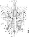
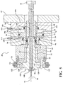
- the collar piston 88 is moveable along the central axis 72, between a locking position, shown in FIG. 5 , and a release position, shown in FIGS. 3 and 4 .
- the collar piston 88 is configured to include a tubular portion 90 disposed about the stem portion 76, and a flange 92 that extends radially outward from the tubular portion 90, away from the central axis 72.
- the tool chuck 50 includes at least one detent ball 94 disposed within a pocket 96 defined by the elongated stem portion 76, between the collar piston 88 and the elongated stem portion 76.
- the tool chuck 50 includes a plurality of detent balls 94, with each detent ball 94 disposed within a respective pocket 96.
- the pocket 96 is sized to support the detent ball 94, such that a portion of the detent ball 94 may extend into the tool receiving bore 70, but the entire detent ball 94 is unable to pass through the pocket 96 into the tool receiving bore 70.
- the detent ball 94 is seated within the pocket 96, but is free to move radially outward away from the central axis 72 when not secured in position by the collar piston 88.
- the male portion 60 of each respective one of the plurality of tools 52 includes a recess 98 shaped to engage the detent ball 94.
- the recess 98 may include, for example, and annular groove extending around a circumference of the male portion 60 of the tool base 58.
- the detent ball 94 When the collar piston 88 is disposed in the locking position, the detent ball 94 is partially disposed within the recess 98 of the male portion 60 of a respective tool 52, in interlocking engagement between the male portion 60 of the respective tool 52 and the collar piston 88, and secured against radial movement relative to the central axis 72 by the collar piston 88.
- the interference between the detent ball 94 and the recess 98 prevents axial movement of the tool 52 along the central axis 72, thereby securing the tool 52 to the tool chuck 50.
- the tool chuck 50 includes an actuating system 100 that is connected to the collar piston 88.
- the actuating system 100 is operable to move the collar piston 88 along the central axis 72.
- the actuating system 100 may include any system capable of moving the collar piston 88 axially along the central axis 72, between the locked position and the release position.
- the tool chuck 50 includes a collar 102 disposed about the collar piston 88.
- the collar 102 includes an inner collar portion 104 and an outer collar portion 106.
- the inner collar portion 104 and the outer collar portion 106 cooperate to define a first fluid chamber 108 and a second fluid chamber 110 that are disposed on opposing axial sides of the flange 92 of the collar piston 88.
- the actuating system 100 includes the first fluid chamber 108 disposed on a first side of the collar piston 88, and connected to a first fluid source 114, and the second fluid chamber 110 disposed on a second side of the collar piston 88, and connected to a second fluid source 118.
- a higher fluid pressure in the first fluid chamber 108 relative to the second fluid chamber 110 biases the collar piston 88 in a first direction along the central axis 72 into the release position.
- the fluid pressure in the first fluid chamber 108 and the second fluid chamber 110 may be provided by, for example, an air pressure source or hydraulic pressure source.
- the locking mechanism 86 and the actuating system 100 may be configured differently than shown and described herein.
- the collar piston 88 may be actuated by an electric solenoid, or other similar device. Accordingly, the locking mechanism 86 and the actuating system 100 should not be limited to the exemplary embodiment shown and described herein.
- the respective tool base 58 of each one of the plurality tools 52 includes a notch 120.
- exemplary embodiment of each respective tool base 58 includes a pair of notches 120 disposed opposite each other, across the central axis 72 from each other.
- the tool holder 54 includes a plurality of holding pins 122, with each of the plurality of holding pins 122 moveably attached to the tool holder 54 and sized to fit within the notch 120 of a respective one of the tools 52 to secure the tool base 58 of the tool 52 to the tool holder 54.
- the holding pins 122 are attached to the tool holder 54 by a respective spring plate 124, best shown in FIGS. 6 and 7 .
- the spring plate 124 biases their respective holding pin 122 toward the central axis 72, into an interlocking position with their respective notch 120.
- the base portion 68 of the tool chuck 50 includes a pair of projections 126, positioned to displace the holding pins 122 from their respective notches 120 of a selected tool 52, in response to axial movement of the tool holder 54 along the X axis 32 toward the chuck holder 42.
- the projections 126 slide into a respective notch 120, thereby displacing the holding pin 122 securing the tool base 58 to the tool holder 54, as the tool holder 54 moves along the X axis 32 toward the tool chuck 50.
- FIG. 3 shows the holding pins 122 disposed in their respective notches 120, with the projections 126just contacting the holding pins 122.
- FIG. 4-6 show the holding pins 122 displaced from their respective notches 120, by one of the projections 126.
- FIG. 7 shows the tool 52 removed from the tool holder 54.
- the tool base 58 of each respective tool 52 includes an annular body 128, with the tool holder 54 defining a semi-annular receiving pocket 130 for each respective tool 52.
- Each receiving pocket 130 is sized to fit the annular body 128 of one of the tools 52. Due to the annular body 128 of the tool base 58, as the tool 52 is moved laterally into the semi-annular receiving pocket 130 of the tool holder 54, the holding pins 122 will ride along the annular body 128 of the tool base 58 until positioned above or below one of the projections 126, such as shown in FIG.
- the semi-annular receiving pocket 130 and the annular body 128 of the tool 52 may include corresponding interlocking features, such as an annular lip 132 that mates with a semi-annular groove 134, to secure the tool 52 relative to the tool holder 54 during movement along the X axis 32.
- the tool 52 cleaning machine includes a machine controller 136.
- the machine controller 136 is operatively connected and capable of controlling the chuck holder 42, the tool chuck 50, the cleaning source, the tool holder 54, the cradle 30, and the part holder 38, as well as any other component of the part cleaning machine 20, whether specifically mentioned or not.
- the machine controller 136 controls the various operations of the part cleaning machine 20 in order to transfer a selected one of the tools 52 between the tool chuck 50 and the tool holder 54, and perform a desired cleaning operation.
- the machine controller 136 may include a control module, such as but not limited to a computer or control unit, to control the operation of the components of the part cleaning machine 20.
- the machine controller 136 may include a computer and/or processor, and include all software, hardware, memory, algorithms, connections, sensors, etc., necessary to manage and control the operation of the part cleaning machine 20. As such, a method, described below, may be embodied as a program operable on the machine controller 136. It should be appreciated that the machine controller 136 may include any device capable of analyzing data from various sensors, comparing data, making the necessary decisions required to control the operation of the part cleaning machine 20, and executing the required tasks necessary to control the operation of the part cleaning machine 20.
- the machine controller 136 may be embodied as one or multiple digital computers or host machines each having one or more processors, read only memory (ROM), random access memory (RAM), electrically-programmable read only memory (EPROM), optical drives, magnetic drives, etc., a high-speed clock, analog-to-digital (A/D) circuitry, digital-to-analog (D/A) circuitry, and any required input/output (I/O) circuitry, I/O devices, and communication interfaces, as well as signal conditioning and buffer electronics.
- ROM read only memory
- RAM random access memory
- EPROM electrically-programmable read only memory
- optical drives magnetic drives, etc.
- a high-speed clock analog-to-digital (A/D) circuitry
- D/A digital-to-analog
- I/O input/output
- the computer-readable memory may include any non-transitory/tangible medium which participates in providing data or computer-readable instructions.
- Memory may be non-volatile or volatile.
- Non-volatile media may include, for example, optical or magnetic disks and other persistent memory.
- Example volatile media may include dynamic random access memory (DRAM), which may constitute a main memory.
- DRAM dynamic random access memory
- Other examples of embodiments for memory include a floppy, flexible disk, or hard disk, magnetic tape or other magnetic medium, a CD-ROM, DVD, and/or any other optical medium, as well as other possible memory devices such as flash memory.
- the machine controller 136 includes tangible, non-transitory memory on which are recorded computer-executable instructions, including a control algorithm.
- the processor of the controller is configured for executing the control algorithm.
- the control algorithm implements a method of operating the part cleaning machine 20, described in greater detail below.
- the machine controller 136 is operable to select one of the plurality of tools 52 appropriate for performing a desired cleaning operation; transfer the selected one of the tools 52 from the tool holder 54 to the tool chuck 50 before starting the desired cleaning operation; position the selected one of the tools 52 in the pre-defined tool 52 cleaning position by moving the chuck holder 42 along at least one of the Y axis 44 and the Z axis 46 on the tool 52 positioning plane; position the part 22 in the pre-defined part 22 cleaning position by at least one of moving the cradle 30 along the X axis 32, rotating the cradle 30 about the first cradle axis 34, or rotating the part holder 38 about the second cradle axis 40; perform the desired cleaning operation on the part 22; and transfer the selected one of the plurality of tools 52 from the cool chuck to the tool holder 54 after the desired cleaning operation is complete.
- the machine controller 136 executes a method of operating the part cleaning machine 20.
- the method includes providing the part cleaning machine 20, such as described in the exemplary embodiment above.
- the part cleaning machine 20 includes: the cradle 30, which is moveable along the X axis 32, and is rotatable about the first cradle axis 34, with the X axis 32 and the first cradle axis 34 being perpendicular to each other; the part holder 38, which is attached to the cradle 30, and is rotatable about the second cradle axis 40 relative to the cradle 30, with the first cradle axis 34 and the second cradle axis 40 being perpendicular to each other; the chuck holder 42, which is moveable along both the Y axis 44 and the Z axis 46, with the Y axis 44 and the Z axis 46 cooperating to form the tool 52 positioning plane that is perpendicular to the X axis 32
- the process of cleaning the part 22 begins by attaching the part 22 to the part holder 38.
- the part 22 is removably attached to the part holder 38.
- the part 22 may be removably attached to the part holder 38 in any suitable manner.
- the specific manner in which the part 22 is attached to the part holder 38 depends on the specific configuration of the part 22, as well as the cleaning operation(s) to be performed, and the position of the part 22 required to perform the cleaning operation.
- a robotic arm may maneuver the part 22 into positon and secure the part 22 to the part holder 38.
- the part 22 may be manually loaded or attached to the part 22 loader.
- the process further includes selecting one of the plurality of tools 52 for performing the desired cleaning operation.
- the machine controller 136 selects the appropriate tool based on the specific part 22 to be cleaned and the desired cleaning operation to be performed.
- the part cleaning machine 20 includes many tools 52, with each tool 52 including a specific tool attachment 62 for performing a specific cleaning operation.
- the specific cleaning operation will depend on the specific type and configuration of the part 22.
- the specific tool 52 required for performing the desired cleaning operation will depend on the configuration of the part 22 and the desired cleaning operation to be performed, i.e., flushing, brushing, deburring, etc.
- the machine controller 136 transfers the selected tool 52 from the tool holder 54 to the tool chuck 50.
- Transferring the selected tool 52 from the tool holder 54 to the tool chuck 50 includes moving the chuck holder 42 along at least one of the Y axis 44 and the Z axis 46 on the tool 52 positioning plane into a pre-defined tool 52 transfer position.
- Each of the plurality of tools 52 will have a corresponding tool 52 transfer position for the tool chuck 50. The specific tool 52 transfer position will therefore depend upon which tool 52 the machine controller 136 selects for the desired cleaning operation.
- the machine controller 136 then moves the tool holder 54 along the X axis 32 and toward the chuck holder 42, until the tool chuck 50 engages the selected tool 52, whereby the selected tool 52 is automatically released from the tool holder 54. As described above, as the tool holder 54 moves toward the tool chuck 50, the projections 126 on the tool chuck 50 displace the holding pins 122 holding the selected tool 52 to the tool holder 54. Once the selected tool 52 has been engaged by the tool chuck 50, the machine controller 136 actuates the locking mechanism 86 to secure the selected tool 52 to the tool chuck 50.
- actuating the locking mechanism 86 includes moving the collar piston 88 from the release position into the locked position. Once the tool 52 is secured to the tool chuck 50 by the locking mechanism 86, the machine controller 136 may then move the tool holder 54 along the X axis 32 and away from the chuck holder 42, thereby moving the selected tool 52 away from and out of engagement with the tool holder 54.
- the machine controller 136 may position the selected tool 52 in a pre-defined tool 52 cleaning position, by moving the chuck holder 42 along at least one of a Y axis 44 and a Z axis 46 on the tool 52 positioning plane.
- the machine controller 136 may also position the part 22 in a pre-defined part 22 cleaning position by moving the cradle 30 along the X axis 32, rotating the cradle 30 about the first cradle axis 34, and/or rotating the part holder 38 about the second cradle axis 40.
- the part 22 cleaning position and tool 52 cleaning position may be fixed positions, or may alternatively be defined movement paths.
- the part 22 cleaning position may present a feature of the part 22 in a fixed position relative to the tool 52 cleaning position, or the part 22 cleaning position may include a path along which the machine controller 136 moves the part 22 during the cleaning operation.
- the tool 52 cleaning position may be a fixed position relative to the part 22 cleaning position, or may include a path along which the machine controller 136 moves the chuck holder 42 and thereby the tool 52 during the cleaning operation.
- the machine controller 136 then continues to perform or execute the desired cleaning operation on the part 22, using the selected tool 52.
- the desired cleaning operation may require the cleaning fluid 66.
- performing the desired cleaning operation may include supplying the tool chuck 50 with the cleaning fluid 66 from the cleaning fluid source 64, whereby the selected tool 52 dispenses the cleaning fluid 66 during the desired cleaning operation.
- the desired cleaning operation may therefore include directing the cleaning fluid 66 through the fluid supply bore 80 of the tool chuck 50 and the internal passage 82 of the selected tool 52.
- the machine controller 136 may then move the part 22 away from the selected tool 52 in the pre-defined tool 52 cleaning position, by moving the cradle 30 along the X axis 32, rotating the cradle 30 about the first cradle axis 34, or rotating the part holder 38 about the second cradle axis 40.
- the machine controller 136 may then transfer the selected tool 52 from the tool chuck 50 to the tool holder 54. Transfer of the selected tool 52 from the tool chuck 50 to the tool holder 54 is similar to the procedure described above for transferring the selected tool 52 from the tool holder 54 to the tool chuck 50.
- transferring the selected tool 52 from the tool chuck 50 to the tool holder 54 includes moving the chuck holder 42 laterally along the Y axis 44 on the tool 52 positioning plane into the pre-defined tool 52 transfer position for the selected tool 52.
- the holding pins 122 engage the annular body 128 of the selected tool 52, and are thereby spread apart 22 as the selected tool 52 is moved into the appropriate tool 52 transfer position.
- the machine controller 136 actuates the locking mechanism 86 to release the selected tool 52 from the tool chuck 50.
- actuating the locking mechanism 86 includes moving the collar piston 88 from the locking position into the release position.
- the machine controller 136 then moves the tool holder 54 along the X axis 32 and away from the chuck holder 42, until the selected tool 52 completely disengages the tool chuck 50.
- the projections 126 on the tool chuck 50 withdraw from the notches 120 in the tool 52 body, thereby allowing the holding pins 122 to move into the notches 120 and secure the tool 52 relative to the tool holder 54.
- the interlocking features between the receiving pocket 130 and the annular body 128 of the tool base 58 e.g., the annular lip 132 and the semi-annular groove 134, engage each other to secure the tool 52 relative to the tool holder 54 as the tool holder 54 moves away from the tool chuck 50.
- the machine controller 136 may then continue with a second desired cleaning operation, using a second selected tool 52. It should be appreciated that the process of performing or executing the second desired cleaning operation with the second selected tool 52 is the same as described above, with the steps described above being repeated for a different one of the tools 52. It should be noted that the tool 52 transfer position will change to reflect the location of the second selected tool 52 on the tool holder 54.
- the machine controller 136 selects the second one of the tools 52 for performing the second desired cleaning operation. As noted above, the specific tool 52 will depend on the desired cleaning operation.
- the second desired tool 52 is then transferred to the tool chuck 50 from the tool holder 54 as described above, with the tool holder 54 and the tool chuck 50 moving into the appropriate second tool 52 transfer position associated with the selected second tool 52.
- the machine controller 136 positions the selected second tool 52 in a second pre-defined tool 52 cleaning position, and positions the part 22 in a second pre-defined part 22 cleaning position, as described above.
- the machine controller 136 then executes the second desired cleaning operation on the part 22.
- the part cleaning machine 20 may perform any number of different cleaning operations on the part 22, using any number of different tools 52 and tool attachments 62, without moving the part 22 to a different machine. Once all of the desired cleaning operations have been performed on the part 22, the part 22 may be released from the part holder 38, and the process is complete.
Landscapes
- Engineering & Computer Science (AREA)
- Mechanical Engineering (AREA)
- Chemical & Material Sciences (AREA)
- Chemical Kinetics & Catalysis (AREA)
- General Chemical & Material Sciences (AREA)
- Auxiliary Devices For Machine Tools (AREA)
- Cleaning By Liquid Or Steam (AREA)
Priority Applications (1)
| Application Number | Priority Date | Filing Date | Title |
|---|---|---|---|
| EP20166539.5A EP3689536B1 (fr) | 2017-01-05 | 2017-12-20 | Methode d'utilisation d'une machine de nettoyage de pièce multi-outils |
Applications Claiming Priority (2)
| Application Number | Priority Date | Filing Date | Title |
|---|---|---|---|
| US201762442474P | 2017-01-05 | 2017-01-05 | |
| US15/715,231 US10661313B2 (en) | 2017-01-05 | 2017-09-26 | Multi-tool part cleaning machine |
Related Child Applications (1)
| Application Number | Title | Priority Date | Filing Date |
|---|---|---|---|
| EP20166539.5A Division EP3689536B1 (fr) | 2017-01-05 | 2017-12-20 | Methode d'utilisation d'une machine de nettoyage de pièce multi-outils |
Publications (2)
| Publication Number | Publication Date |
|---|---|
| EP3345721A1 true EP3345721A1 (fr) | 2018-07-11 |
| EP3345721B1 EP3345721B1 (fr) | 2020-04-22 |
Family
ID=60811815
Family Applications (2)
| Application Number | Title | Priority Date | Filing Date |
|---|---|---|---|
| EP17208849.4A Active EP3345721B1 (fr) | 2017-01-05 | 2017-12-20 | Machine de nettoyage de pièce multi-outils |
| EP20166539.5A Active EP3689536B1 (fr) | 2017-01-05 | 2017-12-20 | Methode d'utilisation d'une machine de nettoyage de pièce multi-outils |
Family Applications After (1)
| Application Number | Title | Priority Date | Filing Date |
|---|---|---|---|
| EP20166539.5A Active EP3689536B1 (fr) | 2017-01-05 | 2017-12-20 | Methode d'utilisation d'une machine de nettoyage de pièce multi-outils |
Country Status (4)
| Country | Link |
|---|---|
| US (2) | US10661313B2 (fr) |
| EP (2) | EP3345721B1 (fr) |
| CN (2) | CN108273790B (fr) |
| CA (1) | CA2988928C (fr) |
Families Citing this family (4)
| Publication number | Priority date | Publication date | Assignee | Title |
|---|---|---|---|---|
| CN111097772A (zh) * | 2019-12-13 | 2020-05-05 | 上海交通大学 | 一种用于火箭贮箱清洗的三自由度翻转台 |
| CN113663941B (zh) * | 2020-05-13 | 2022-12-27 | 上海蓝浦清洗技术有限公司 | 一种机械零部件表面污垢清洗设备及其环保清洗剂 |
| CN112476006A (zh) * | 2020-11-19 | 2021-03-12 | 南通格美工业数控设备有限公司 | 一种大型精密五轴联动数控加工中心 |
| CN113386021B (zh) * | 2021-06-29 | 2022-03-11 | 徐州超杰电动车配件有限公司 | 一种电动车配件用的打磨装置 |
Citations (4)
| Publication number | Priority date | Publication date | Assignee | Title |
|---|---|---|---|---|
| EP1201351A2 (fr) * | 2000-10-26 | 2002-05-02 | Mori Seiki Co., Ltd. | Machine-outil avec dispositifs de protection pour pièces de machine |
| EP1882544A1 (fr) * | 2006-07-24 | 2008-01-30 | Deckel Maho Seebach GmbH | Fraiseuse et perceuse |
| GB2496869A (en) * | 2011-11-23 | 2013-05-29 | Philip David Jones | Coolant powered swarf removal tool |
| JP2015217492A (ja) * | 2014-05-20 | 2015-12-07 | エンシュウ株式会社 | 工作機械 |
Family Cites Families (16)
| Publication number | Priority date | Publication date | Assignee | Title |
|---|---|---|---|---|
| DE59104722D1 (de) * | 1991-10-19 | 1995-03-30 | Index Werke Kg Hahn & Tessky | Drehmaschine. |
| JP3942733B2 (ja) * | 1998-06-01 | 2007-07-11 | 日立ビアメカニクス株式会社 | ワーク加工装置 |
| US7386911B2 (en) * | 2004-11-11 | 2008-06-17 | Ford Motor Company | Apparatus for dislodging and removing contaminants from a surface of a machine tool |
| JP4342474B2 (ja) * | 2005-05-25 | 2009-10-14 | 株式会社森精機製作所 | 工作機械 |
| JP2007136477A (ja) * | 2005-11-16 | 2007-06-07 | Disco Abrasive Syst Ltd | レーザー加工装置 |
| JP4171507B2 (ja) * | 2006-09-08 | 2008-10-22 | 株式会社森精機製作所 | 工作機械 |
| KR101210979B1 (ko) * | 2007-11-27 | 2012-12-11 | 미쓰보시 다이야몬도 고교 가부시키가이샤 | 레이저 가공 장치 |
| ES2337860B8 (es) * | 2007-12-19 | 2011-07-28 | Airbus Operations, S.L. | Procedimiento para la preparacion y limpieza de utiles de fabricacionde piezas de material compuesto, y dispositivo correspondiente. |
| ITTV20080109A1 (it) * | 2008-08-19 | 2010-02-20 | Breton Spa | Metodo e dispositivo per la misurazione ed il controllo dello spessore di strutture |
| DE102008050656A1 (de) * | 2008-09-22 | 2010-03-25 | Traub Drehmaschinen Gmbh & Co. Kg | Werkzeugmaschine |
| DE102011116833A1 (de) * | 2010-12-22 | 2012-06-28 | Bystronic Laser Ag | Laserbearbeitungsmaschine und Verfahren zur Bearbeitung eines Werkstücks |
| JP5774360B2 (ja) * | 2011-04-25 | 2015-09-09 | オークマ株式会社 | 工作機械のテーブルユニット |
| DE102012100614A1 (de) * | 2011-07-19 | 2013-01-24 | Index-Werke Gmbh & Co. Kg Hahn & Tessky | Drehmaschine |
| JP2015047621A (ja) * | 2013-09-02 | 2015-03-16 | 三菱重工業株式会社 | 複合加工装置及び複合加工方法 |
| JP6580832B2 (ja) * | 2015-01-22 | 2019-09-25 | エンシュウ株式会社 | 工作機械および原姿勢復帰処理プログラム |
| CN105500020A (zh) * | 2016-01-18 | 2016-04-20 | 嘉泰数控科技股份公司 | 门型五轴数控加工中心 |
-
2017
- 2017-09-26 US US15/715,231 patent/US10661313B2/en active Active
- 2017-12-14 CA CA2988928A patent/CA2988928C/fr active Active
- 2017-12-20 EP EP17208849.4A patent/EP3345721B1/fr active Active
- 2017-12-20 EP EP20166539.5A patent/EP3689536B1/fr active Active
-
2018
- 2018-01-03 CN CN201810004046.9A patent/CN108273790B/zh active Active
- 2018-01-03 CN CN202111419119.9A patent/CN114733819A/zh active Pending
-
2020
- 2020-04-15 US US16/849,814 patent/US11192150B2/en active Active
Patent Citations (4)
| Publication number | Priority date | Publication date | Assignee | Title |
|---|---|---|---|---|
| EP1201351A2 (fr) * | 2000-10-26 | 2002-05-02 | Mori Seiki Co., Ltd. | Machine-outil avec dispositifs de protection pour pièces de machine |
| EP1882544A1 (fr) * | 2006-07-24 | 2008-01-30 | Deckel Maho Seebach GmbH | Fraiseuse et perceuse |
| GB2496869A (en) * | 2011-11-23 | 2013-05-29 | Philip David Jones | Coolant powered swarf removal tool |
| JP2015217492A (ja) * | 2014-05-20 | 2015-12-07 | エンシュウ株式会社 | 工作機械 |
Also Published As
| Publication number | Publication date |
|---|---|
| US11192150B2 (en) | 2021-12-07 |
| EP3345721B1 (fr) | 2020-04-22 |
| US10661313B2 (en) | 2020-05-26 |
| US20200238343A1 (en) | 2020-07-30 |
| CN108273790A (zh) | 2018-07-13 |
| CN114733819A (zh) | 2022-07-12 |
| CA2988928A1 (fr) | 2018-07-05 |
| US20180185887A1 (en) | 2018-07-05 |
| CA2988928C (fr) | 2020-01-07 |
| CN108273790B (zh) | 2021-12-07 |
| EP3689536A1 (fr) | 2020-08-05 |
| EP3689536B1 (fr) | 2023-07-05 |
Similar Documents
| Publication | Publication Date | Title |
|---|---|---|
| US11192150B2 (en) | Multi-tool part cleaning machine | |
| US8985564B2 (en) | Workpiece holding fixture for machining multiple prismatic parts | |
| CN110480392B (zh) | 一种加工中心的智能刀库系统和智能刀库系统运行方法 | |
| US11712770B2 (en) | Machine tool | |
| US20190232448A1 (en) | Feeding device for a tool magazine of a machine tool and method for changing a tool on a tool magazine | |
| JPS59175984A (ja) | 工業用ロボツトのハンド交換装置 | |
| US10571357B2 (en) | Leak check system and method of checking leak using the same | |
| JP2010099820A (ja) | クランプ装置、クランプ装置による旋盤の円筒ワーク加工方法、クランプ装置によるフライス盤の円筒ワーク加工方法。 | |
| US20170282319A1 (en) | Workpiece holding fixture for machining multiple prismatic parts | |
| KR102319337B1 (ko) | 터릿 공구대 장치 및 이의 공구 교환방법 | |
| US9050671B2 (en) | Electrode holder for EDM coupled to a milling machine | |
| US20170282314A1 (en) | Workpiece holding fixture for machining multiple prismatic parts | |
| JP2020062700A (ja) | 冷却液供給装置 | |
| JP2010537836A (ja) | 機械加工装置および方法 | |
| US3492717A (en) | Machine tool | |
| CN112238463B (zh) | 工具头更换系统 | |
| CN116547106A (zh) | 对具备保持多个工具的工具保持机构的对象装置的工具进行管理的工具管理装置 | |
| JPH08197311A (ja) | 多軸自動旋盤のクーラント供給装置 | |
| CN224182694U (zh) | 一种加工单元分布组合式加工设备 | |
| JP2005161455A (ja) | 工作機械のワーク位置決めクランプ制御装置およびその制御方法 | |
| JP3042287B2 (ja) | 多軸工作機械の自動工具交換装置 | |
| JP2006144926A (ja) | 流体カプラ装置及びこれを備えた加工機 | |
| JP2006021274A (ja) | ローダ装置の段取り替え部品 | |
| JPH0531690A (ja) | 工具保持装置 | |
| JPS61257737A (ja) | マシニングセンタにおける自動工具交換装置 |
Legal Events
| Date | Code | Title | Description |
|---|---|---|---|
| PUAI | Public reference made under article 153(3) epc to a published international application that has entered the european phase |
Free format text: ORIGINAL CODE: 0009012 |
|
| STAA | Information on the status of an ep patent application or granted ep patent |
Free format text: STATUS: THE APPLICATION HAS BEEN PUBLISHED |
|
| AK | Designated contracting states |
Kind code of ref document: A1 Designated state(s): AL AT BE BG CH CY CZ DE DK EE ES FI FR GB GR HR HU IE IS IT LI LT LU LV MC MK MT NL NO PL PT RO RS SE SI SK SM TR |
|
| AX | Request for extension of the european patent |
Extension state: BA ME |
|
| STAA | Information on the status of an ep patent application or granted ep patent |
Free format text: STATUS: REQUEST FOR EXAMINATION WAS MADE |
|
| 17P | Request for examination filed |
Effective date: 20180726 |
|
| RBV | Designated contracting states (corrected) |
Designated state(s): AL AT BE BG CH CY CZ DE DK EE ES FI FR GB GR HR HU IE IS IT LI LT LU LV MC MK MT NL NO PL PT RO RS SE SI SK SM TR |
|
| STAA | Information on the status of an ep patent application or granted ep patent |
Free format text: STATUS: EXAMINATION IS IN PROGRESS |
|
| 17Q | First examination report despatched |
Effective date: 20190306 |
|
| GRAP | Despatch of communication of intention to grant a patent |
Free format text: ORIGINAL CODE: EPIDOSNIGR1 |
|
| STAA | Information on the status of an ep patent application or granted ep patent |
Free format text: STATUS: GRANT OF PATENT IS INTENDED |
|
| INTG | Intention to grant announced |
Effective date: 20191115 |
|
| RAP1 | Party data changed (applicant data changed or rights of an application transferred) |
Owner name: FIVES CINETIC CORP. |
|
| GRAS | Grant fee paid |
Free format text: ORIGINAL CODE: EPIDOSNIGR3 |
|
| GRAA | (expected) grant |
Free format text: ORIGINAL CODE: 0009210 |
|
| STAA | Information on the status of an ep patent application or granted ep patent |
Free format text: STATUS: THE PATENT HAS BEEN GRANTED |
|
| AK | Designated contracting states |
Kind code of ref document: B1 Designated state(s): AL AT BE BG CH CY CZ DE DK EE ES FI FR GB GR HR HU IE IS IT LI LT LU LV MC MK MT NL NO PL PT RO RS SE SI SK SM TR |
|
| REG | Reference to a national code |
Ref country code: CH Ref legal event code: EP |
|
| REG | Reference to a national code |
Ref country code: IE Ref legal event code: FG4D |
|
| REG | Reference to a national code |
Ref country code: DE Ref legal event code: R096 Ref document number: 602017015141 Country of ref document: DE |
|
| REG | Reference to a national code |
Ref country code: AT Ref legal event code: REF Ref document number: 1259443 Country of ref document: AT Kind code of ref document: T Effective date: 20200515 |
|
| REG | Reference to a national code |
Ref country code: LT Ref legal event code: MG4D |
|
| REG | Reference to a national code |
Ref country code: NL Ref legal event code: MP Effective date: 20200422 |
|
| PG25 | Lapsed in a contracting state [announced via postgrant information from national office to epo] |
Ref country code: GR Free format text: LAPSE BECAUSE OF FAILURE TO SUBMIT A TRANSLATION OF THE DESCRIPTION OR TO PAY THE FEE WITHIN THE PRESCRIBED TIME-LIMIT Effective date: 20200723 Ref country code: NO Free format text: LAPSE BECAUSE OF FAILURE TO SUBMIT A TRANSLATION OF THE DESCRIPTION OR TO PAY THE FEE WITHIN THE PRESCRIBED TIME-LIMIT Effective date: 20200722 Ref country code: PT Free format text: LAPSE BECAUSE OF FAILURE TO SUBMIT A TRANSLATION OF THE DESCRIPTION OR TO PAY THE FEE WITHIN THE PRESCRIBED TIME-LIMIT Effective date: 20200824 Ref country code: SE Free format text: LAPSE BECAUSE OF FAILURE TO SUBMIT A TRANSLATION OF THE DESCRIPTION OR TO PAY THE FEE WITHIN THE PRESCRIBED TIME-LIMIT Effective date: 20200422 Ref country code: NL Free format text: LAPSE BECAUSE OF FAILURE TO SUBMIT A TRANSLATION OF THE DESCRIPTION OR TO PAY THE FEE WITHIN THE PRESCRIBED TIME-LIMIT Effective date: 20200422 Ref country code: LT Free format text: LAPSE BECAUSE OF FAILURE TO SUBMIT A TRANSLATION OF THE DESCRIPTION OR TO PAY THE FEE WITHIN THE PRESCRIBED TIME-LIMIT Effective date: 20200422 Ref country code: FI Free format text: LAPSE BECAUSE OF FAILURE TO SUBMIT A TRANSLATION OF THE DESCRIPTION OR TO PAY THE FEE WITHIN THE PRESCRIBED TIME-LIMIT Effective date: 20200422 Ref country code: IS Free format text: LAPSE BECAUSE OF FAILURE TO SUBMIT A TRANSLATION OF THE DESCRIPTION OR TO PAY THE FEE WITHIN THE PRESCRIBED TIME-LIMIT Effective date: 20200822 |
|
| REG | Reference to a national code |
Ref country code: AT Ref legal event code: MK05 Ref document number: 1259443 Country of ref document: AT Kind code of ref document: T Effective date: 20200422 |
|
| PG25 | Lapsed in a contracting state [announced via postgrant information from national office to epo] |
Ref country code: LV Free format text: LAPSE BECAUSE OF FAILURE TO SUBMIT A TRANSLATION OF THE DESCRIPTION OR TO PAY THE FEE WITHIN THE PRESCRIBED TIME-LIMIT Effective date: 20200422 Ref country code: HR Free format text: LAPSE BECAUSE OF FAILURE TO SUBMIT A TRANSLATION OF THE DESCRIPTION OR TO PAY THE FEE WITHIN THE PRESCRIBED TIME-LIMIT Effective date: 20200422 Ref country code: RS Free format text: LAPSE BECAUSE OF FAILURE TO SUBMIT A TRANSLATION OF THE DESCRIPTION OR TO PAY THE FEE WITHIN THE PRESCRIBED TIME-LIMIT Effective date: 20200422 Ref country code: BG Free format text: LAPSE BECAUSE OF FAILURE TO SUBMIT A TRANSLATION OF THE DESCRIPTION OR TO PAY THE FEE WITHIN THE PRESCRIBED TIME-LIMIT Effective date: 20200722 |
|
| PG25 | Lapsed in a contracting state [announced via postgrant information from national office to epo] |
Ref country code: AL Free format text: LAPSE BECAUSE OF FAILURE TO SUBMIT A TRANSLATION OF THE DESCRIPTION OR TO PAY THE FEE WITHIN THE PRESCRIBED TIME-LIMIT Effective date: 20200422 |
|
| REG | Reference to a national code |
Ref country code: DE Ref legal event code: R097 Ref document number: 602017015141 Country of ref document: DE |
|
| PG25 | Lapsed in a contracting state [announced via postgrant information from national office to epo] |
Ref country code: ES Free format text: LAPSE BECAUSE OF FAILURE TO SUBMIT A TRANSLATION OF THE DESCRIPTION OR TO PAY THE FEE WITHIN THE PRESCRIBED TIME-LIMIT Effective date: 20200422 Ref country code: RO Free format text: LAPSE BECAUSE OF FAILURE TO SUBMIT A TRANSLATION OF THE DESCRIPTION OR TO PAY THE FEE WITHIN THE PRESCRIBED TIME-LIMIT Effective date: 20200422 Ref country code: CZ Free format text: LAPSE BECAUSE OF FAILURE TO SUBMIT A TRANSLATION OF THE DESCRIPTION OR TO PAY THE FEE WITHIN THE PRESCRIBED TIME-LIMIT Effective date: 20200422 Ref country code: DK Free format text: LAPSE BECAUSE OF FAILURE TO SUBMIT A TRANSLATION OF THE DESCRIPTION OR TO PAY THE FEE WITHIN THE PRESCRIBED TIME-LIMIT Effective date: 20200422 Ref country code: SM Free format text: LAPSE BECAUSE OF FAILURE TO SUBMIT A TRANSLATION OF THE DESCRIPTION OR TO PAY THE FEE WITHIN THE PRESCRIBED TIME-LIMIT Effective date: 20200422 Ref country code: AT Free format text: LAPSE BECAUSE OF FAILURE TO SUBMIT A TRANSLATION OF THE DESCRIPTION OR TO PAY THE FEE WITHIN THE PRESCRIBED TIME-LIMIT Effective date: 20200422 Ref country code: EE Free format text: LAPSE BECAUSE OF FAILURE TO SUBMIT A TRANSLATION OF THE DESCRIPTION OR TO PAY THE FEE WITHIN THE PRESCRIBED TIME-LIMIT Effective date: 20200422 |
|
| PG25 | Lapsed in a contracting state [announced via postgrant information from national office to epo] |
Ref country code: PL Free format text: LAPSE BECAUSE OF FAILURE TO SUBMIT A TRANSLATION OF THE DESCRIPTION OR TO PAY THE FEE WITHIN THE PRESCRIBED TIME-LIMIT Effective date: 20200422 Ref country code: SK Free format text: LAPSE BECAUSE OF FAILURE TO SUBMIT A TRANSLATION OF THE DESCRIPTION OR TO PAY THE FEE WITHIN THE PRESCRIBED TIME-LIMIT Effective date: 20200422 |
|
| PLBE | No opposition filed within time limit |
Free format text: ORIGINAL CODE: 0009261 |
|
| STAA | Information on the status of an ep patent application or granted ep patent |
Free format text: STATUS: NO OPPOSITION FILED WITHIN TIME LIMIT |
|
| 26N | No opposition filed |
Effective date: 20210125 |
|
| PG25 | Lapsed in a contracting state [announced via postgrant information from national office to epo] |
Ref country code: SI Free format text: LAPSE BECAUSE OF FAILURE TO SUBMIT A TRANSLATION OF THE DESCRIPTION OR TO PAY THE FEE WITHIN THE PRESCRIBED TIME-LIMIT Effective date: 20200422 |
|
| REG | Reference to a national code |
Ref country code: DE Ref legal event code: R119 Ref document number: 602017015141 Country of ref document: DE |
|
| REG | Reference to a national code |
Ref country code: CH Ref legal event code: PL |
|
| PG25 | Lapsed in a contracting state [announced via postgrant information from national office to epo] |
Ref country code: MC Free format text: LAPSE BECAUSE OF FAILURE TO SUBMIT A TRANSLATION OF THE DESCRIPTION OR TO PAY THE FEE WITHIN THE PRESCRIBED TIME-LIMIT Effective date: 20200422 |
|
| REG | Reference to a national code |
Ref country code: BE Ref legal event code: MM Effective date: 20201231 |
|
| PG25 | Lapsed in a contracting state [announced via postgrant information from national office to epo] |
Ref country code: IE Free format text: LAPSE BECAUSE OF NON-PAYMENT OF DUE FEES Effective date: 20201220 Ref country code: LU Free format text: LAPSE BECAUSE OF NON-PAYMENT OF DUE FEES Effective date: 20201220 |
|
| PG25 | Lapsed in a contracting state [announced via postgrant information from national office to epo] |
Ref country code: LI Free format text: LAPSE BECAUSE OF NON-PAYMENT OF DUE FEES Effective date: 20201231 Ref country code: DE Free format text: LAPSE BECAUSE OF NON-PAYMENT OF DUE FEES Effective date: 20210701 Ref country code: CH Free format text: LAPSE BECAUSE OF NON-PAYMENT OF DUE FEES Effective date: 20201231 |
|
| PG25 | Lapsed in a contracting state [announced via postgrant information from national office to epo] |
Ref country code: TR Free format text: LAPSE BECAUSE OF FAILURE TO SUBMIT A TRANSLATION OF THE DESCRIPTION OR TO PAY THE FEE WITHIN THE PRESCRIBED TIME-LIMIT Effective date: 20200422 Ref country code: MT Free format text: LAPSE BECAUSE OF FAILURE TO SUBMIT A TRANSLATION OF THE DESCRIPTION OR TO PAY THE FEE WITHIN THE PRESCRIBED TIME-LIMIT Effective date: 20200422 Ref country code: CY Free format text: LAPSE BECAUSE OF FAILURE TO SUBMIT A TRANSLATION OF THE DESCRIPTION OR TO PAY THE FEE WITHIN THE PRESCRIBED TIME-LIMIT Effective date: 20200422 |
|
| PG25 | Lapsed in a contracting state [announced via postgrant information from national office to epo] |
Ref country code: MK Free format text: LAPSE BECAUSE OF FAILURE TO SUBMIT A TRANSLATION OF THE DESCRIPTION OR TO PAY THE FEE WITHIN THE PRESCRIBED TIME-LIMIT Effective date: 20200422 |
|
| PG25 | Lapsed in a contracting state [announced via postgrant information from national office to epo] |
Ref country code: BE Free format text: LAPSE BECAUSE OF NON-PAYMENT OF DUE FEES Effective date: 20201231 |
|
| GBPC | Gb: european patent ceased through non-payment of renewal fee |
Effective date: 20211220 |
|
| PG25 | Lapsed in a contracting state [announced via postgrant information from national office to epo] |
Ref country code: GB Free format text: LAPSE BECAUSE OF NON-PAYMENT OF DUE FEES Effective date: 20211220 |
|
| PGFP | Annual fee paid to national office [announced via postgrant information from national office to epo] |
Ref country code: IT Payment date: 20251119 Year of fee payment: 9 |
|
| PGFP | Annual fee paid to national office [announced via postgrant information from national office to epo] |
Ref country code: FR Payment date: 20251120 Year of fee payment: 9 |