EP3345727A1 - Outil de serrage multi-magazine - Google Patents
Outil de serrage multi-magazine Download PDFInfo
- Publication number
- EP3345727A1 EP3345727A1 EP18154402.4A EP18154402A EP3345727A1 EP 3345727 A1 EP3345727 A1 EP 3345727A1 EP 18154402 A EP18154402 A EP 18154402A EP 3345727 A1 EP3345727 A1 EP 3345727A1
- Authority
- EP
- European Patent Office
- Prior art keywords
- magazine
- clamps
- clamp
- tool
- ramming
- Prior art date
- Legal status (The legal status is an assumption and is not a legal conclusion. Google has not performed a legal analysis and makes no representation as to the accuracy of the status listed.)
- Granted
Links
Images



Classifications
-
- B—PERFORMING OPERATIONS; TRANSPORTING
- B25—HAND TOOLS; PORTABLE POWER-DRIVEN TOOLS; MANIPULATORS
- B25C—HAND-HELD NAILING OR STAPLING TOOLS; MANUALLY OPERATED PORTABLE STAPLING TOOLS
- B25C5/00—Manually operated portable stapling tools; Hand-held power-operated stapling tools; Staple feeding devices therefor
- B25C5/16—Staple-feeding devices, e.g. with feeding means, supports for staples or accessories concerning feeding devices
- B25C5/1637—Supports for the staples being fed
- B25C5/1641—Supports for the staples being fed allowing the feeding of a variety of elements
- B25C5/1644—Supports for the staples being fed allowing the feeding of a variety of elements of different shapes
-
- H—ELECTRICITY
- H02—GENERATION; CONVERSION OR DISTRIBUTION OF ELECTRIC POWER
- H02G—INSTALLATION OF ELECTRIC CABLES OR LINES, OR OF COMBINED OPTICAL AND ELECTRIC CABLES OR LINES
- H02G3/00—Installations of electric cables or lines or protective tubing therefor in or on buildings, equivalent structures or vehicles
- H02G3/30—Installations of cables or lines on walls, floors or ceilings
- H02G3/32—Installations of cables or lines on walls, floors or ceilings using mounting clamps
Definitions
- the present invention relates to a method for bringing a clamp from a magazine in a tool to a barrel or bore for driving a clamp into a supporting surface by means of a ramming bolt which is moveably back and fro inside the barrel or bore, where a plurality of clamps are held by a magazine that is arranged in a tool, and wherein one or one clamp is transferred from the magazine to the barrel or bore.
- a tool comprising a housing containing one in axial direction moveable hammer bolt, a magazine that may be substituted for storing a set of clamps and a loading mechanism for bringing one and one clamp from the magazine to a position inside the barrel or bore, where the ramming bolt plug is configured to drive the clamp out of the tool and into the supporting surface.
- clamps of different types are used, dependent on the size of the cable, the material used in the supporting surface, and so on.
- Common features for such cables are firstly to penetrate the supporting surface and secondly to enclose completely or at least partly a part of the free surface of a cable.
- a hand tool with a magazine with clamps for fixing electrical cables to a supporting surface
- the tool comprises a housing containing a device for holding a magazine with stacked clamps arranged in a row.
- Such clamps are delivered stacked and stored in the magazine from the supplier, where the clamps are arranged in a line or row with the clamp end that is intended to enclose at least a part of the electrical cable is positioned down into a duct with a more or less U-shaped cross sectional area.
- the magazine, filled with clamps is inserted into a ramming tool which is provided with a housing encompassing the magazine and comprising a ramming piston or bolt designed to move back and fro in e barrel or bore.
- the piston may move between two extreme positions, namely a retracted position where the piston is retracted to an inner extreme position, allowing a clamp to be inserted into the barrel or bore just in front of the piston; and another extreme position, where the piston is moved so much forward in the barrel or bore that the clamp is forced into the supporting surface.
- a retracted position where the piston is retracted to an inner extreme position, allowing a clamp to be inserted into the barrel or bore just in front of the piston
- another extreme position where the piston is moved so much forward in the barrel or bore that the clamp is forced into the supporting surface.
- the rear end of the ramming bolt extends preferably still out from the rear end of the barrel or bore.
- the ramming bolt has a length that is configured such that the rear end preferably always will project out of the barrel or bore, while the forward end being moved between two extreme positions; one where the ram is retracted backwards and a clamp is allowed to enter the barrel or bore, and a second position where the clamp is driven into the supporting surface by means of the ram.
- the clamps are brought along an inclined path into the barrel or bore and more than one clamp are at any time arranged inside the clamping tool.
- This solution is completely adapted to be used for only one type of clamps, where the locking head, i.e. the part of the clamp intended to surround the cable, is in the form of two parallel fingers, arranged in a spaced relation.
- the ramming bolt is configured such that it is moving past all the clamps arranged within the chamber, except for the clamp thar at any time being the first claim inside the magazine.
- the invention is based on using the very same tool for a large variety of different types of clamps, arranged in magazines, where the clamps are fed forward in one direction, where the first clamp is separated from the rest of the clamps, wherein said first clamp is fed in a transverse direction into a barrel or bore and where the first clamp is forced out of the barrel or bore by means of a ramming device, whereupon a new loading sequence is taken, and the process is repeated.
- An object of the invention is to provide a ramming tool with a magazine, where the one and same tool is configured to be adapted to a variety of different types of clamps..
- Another object of the invention is to provide an improved ramming tool which is easy in use, separating the first clamp from the remaining clamps, and where the risk of jamming of two clamps in the barrel or bore at the same time is eliminated or at least substantially reduced.
- a still further object of the invention is to provide one type of magazine that is particularly adapted to the ramming tool, where said one and the same magazine also is configured for storing different types of clamps without having to adapt or modify the magazine individually.
- Yet another object of the invention is to provide a solution that simplifies and makes efficient clamping of cables to a supporting surface, where the electrician will be able to reduce the time taken for fixing the cables to the supporting surface.
- a still further object of the invention is to provide an improved tool where the operator only requires taking two loading and charging grips in order to charge and load a clamp into a clamping position around a cable.
- a tool for fixing electrical cables to a supporting surface by means of clamps comprises a housing containing a ramming bolt which is movable in an axial direction, a replaceable magazine for storing of a set pf clamps and a loading or charging mechanism for bringing one and one clamp at the time from the magazine to a position in a barrel or bore.
- the ramming bolt is configured to drive and force the clamp out of the tool and into the supporting surface.
- the tool comprises a mechanism configured to separate the very first clamp from the remaining clamps in the magazine.
- the mechanism for separating the first clamp from the second clamp in the magazine, and possibly the remaining clamps in the magazine comprises a spring biased, movable part intended to rest against one side of a clamp head of the last clamp in the magazine and a stationary part intended to function as a stop surface for the first clamp in the magazine.
- the movable part provides a force in one direction on the clamps in the magazine and presses the first clamp against the stationary part, so that leg(s) of the first clamps is or are tilted upwards while the second clamp in the magazine is locked against movement by means of a movable tailpiece, configured to move in below said upwards tilted leg(s).
- Said stationary part may be provided with a surface facing the first clamp and is skewed downwards and away from the magazine and where the stationary part at its lower end is provided with a surface inclined in upwards direction and away from the magazine, said device for separate clamps being configured to apply a separating force (F) to the clamps when the ramming bolt is pulled back.
- F separating force
- the tool may comprise a loading and charging mechanism that moves the first clamp in a magazine in one direction and a device for bringing the first clamp from the magazine in a lateral or sideways direction into the barrel or bore, for subsequent driving the clamp into a supporting surface by means of the ramming bolt.
- the loading or charging mechanism comprises a rider that creates a force in one direction on the clamps in the magazine and pressing the first clamp against a stationary surface that is configured for tilting the leg(s) of the first clamp upwards and a tailpiece that is configured to be moved under said upwards tilted leg(s) of the first clamp for locking the second clamp and the remaining clamps in the magazine against movement.
- said stationary surface may be arranged on a clamp separator, where the stationary surface is skewed downwards and away from the magazine, and where the clamp separator at its lower end is provided with a surface that is skewed upwards and away from the magazine.
- Said clamp separator together with a movable rider, apply a force on the first clamp that makes the first clamp tilting up and such that the tailpiece is brought in between the first clamp and the second clamp, and applies a locking force on the second clamp and the remaining clamps in the magazine when the ramming bolt is pulled back, at the same time as the same motion of the ramming bolt backwards also secures that the tailpiece is providing the separation of the first clamp from the second clamp and also the remaining clamps.
- the loading and charging mechanism may possibly comprise a magnet arranged in such way with respect to the ramming bolt that first clamp completely or at least partly is free with respect to the ramming bolt when it is in its extreme position, ready to force a clamp into the supporting surface, such that the clamp may be brought into the barrel or bore.
- the clamp separator may be configured to retain the upstream clamps in the magazine such that the first clam in front is allowed to move with respect to said remaining upstream clamps.
- the first clamp is retained in position in the barrel or bore by means of one or more magnets arranged in the wall of the barrel or bore.
- a ramming bolt In order to bring a clamp from a magazine inserted in the tool to the barrel or bore for ramming into a supporting surface, a ramming bolt may be used.
- the ramming bolt is movable back and fro in the barrel or bore.
- a plurality of clamps are arranged in a magazine which is inserted into the tool, where one clamp at the time is transferred from the magazine to the barrel or bore.
- the clamps are brought to be moved forward in the magazine in parallel with the barrel or bore, whereupon a first clamp in the magazine is separated from the remaining clamps in the magazine by means of a separating device.
- the separated first clamp is then brought to move sideways and into the barrel or bore, in front of the ramming bolt, which in this phase is retracted completely in the barrel or bore.
- the last clamp in the magazine may preferably be exposed to a pressure by a rider that presses an edge on the first clamp against a surface on the clamp separating device, so that the first clamp may be rotated around said edge, whereupon the tailpiece is moved under the upwards tilted first clamp to come in contact with the second clamp for temporarily to hold the second clamp back, the motion of the tailpiece preferably being obtained by pulling the ramming bolt backwards to an extreme retracted position.
- the first clamp may preferably be brought to move laterally into the barrel or bore when the first clamp is freed off the remaining clamps, by means of a magnet arranged on an adjacent wall in the barrel or bore.
- a first clamp is separated from the next, second clamp in the magazine, said second clamp being locked from movement out of the magazine, while said first clamp is allowed to be transferred into a barrel or bore in order to be rammed into a supporting surface.
- the clamps are brought to be moved forward in the magazine in parallel with the barrel or bore, whereupon a first clamp in the magazine is separated from the remaining clamps in the magazine by means of a separating device, whereupon the separated first clamp is brought to be moved sideways and into the barrel or bore, in front of the ramming bolt, which during this phase is completely retracted in the barrel or bore.
- a last clamp in the magazine is subjected to a pressure by means of a rider that presses an edge on the first clamp against a surface on the clamp separating device so that the first clamp may rotate around said edge, whereupon a tailpiece is moved under the tilted first clamp into contact with a second clamp for temporarily to retain this second clamp back from movement, the movement of the tailpiece preferably being achieved by pulling the ramming bolt backwards in the barrel to an extreme, rearwards position.
- the first clamp may be brought to a lateral movement into the barrel or bore when released from the remaining clamps by means of a magnet arranged in an adjacent wall inside the barrel or bore.
- the housing enclosing and surrounding the respective tool mechanisms is not shown for the purpose of clarity and simplicity. Moreover, several details of minor importance or relevance are also omitted. Further, the same reference numbers are use in the different Figures for the same or similar elements or features. Although only clamps with one leg are shown, the clamps may also have three legs.
- Figures 1a to 1d show some of the typical clamps that are suitable to be used in the magazine and for insertion into a tool according to the present invention.
- the tool according to the invention is not limited for application of the clamps shown, however, since also other corresponding or similar types of clamps may be used.
- the clamps shown in the Figures 1a and 1b are of the so-called TP-clamps, equipped with one leg 1 and one head 2, the head 2 being intended to partly surround an electrical cable or line (not shown), where the head cooperate with a purpose shaped end of the ramming bolt.
- Figures 1c and 1d shows two different variants of clamps for gypsum plates, comprising three legs 1 and a head 2 with a hole corresponding to the ones associated with the TP-clamps. Even though the clamps shown in Figures 1a to 1d are shown having an hole, it should be appreciated that the solution according to the present invention will function in an appropriate manner also for clamps without such holes. Moreover, it should be appreciated that clamps with a different number of legs also may be used in connection with the invention..
- FIG. 2 shows schematically, seen from one side, an embodiment of the tool 10 according to the present invention.
- the tool 10 comprises a housing 21 which encapsulates a replaceable magazine 11 containing clamps 12 for attachment to a supporting surface; ramming bolt 17; and the required mechanisms necessary for bringing one clamps from the magazine 11 to appropriate position in a barrel or bore 16, in front of the ramming tool 17.
- a housing 21 which encapsulates a replaceable magazine 11 containing clamps 12 for attachment to a supporting surface
- ramming bolt 17 and the required mechanisms necessary for bringing one clamps from the magazine 11 to appropriate position in a barrel or bore 16, in front of the ramming tool 17.
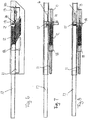
- Figure 3 shows schematically in perspective an embodiment of a tool 10 according to the present invention, seen from the side of the tool 10 with the housing removed, where a magazine 11 is arranged in a parallel position with and sideways displaced in respect of a barrel or bore, and a ramming bolt.
- the tool 10 comprises a magazine 11 (shown schematically) containing a number of clamps 12 arranged in a row, one in front of the others with the head 2 arranged at the top and with legs 1 pointing skewed downwards and forward, a clamp separating device 13, a tailpiece 14, a device 15 for moving the first clamp from the clamp separating device 13 into a barrel or bore 18 and a ramming bolt 17 that may be moved back and fro inside the barrel or bore 16, intended to for forcing the clamp 12 into a supporting surface /not shown).
- the clamps 12 are arranged in the magazine 11 and in the tool 10 such that the free ends of the legs, i.e. the parts of the clamps intended to be forced into the supporting surface, are pointing skewed downwards and forward in respect of the tool 10 (towards the right in the Figures).
- the clamps 12 are stored more or less in a compressed state between a rider 18 and the clamp separating device 19, while the walls of the magazine 11 secures that the clamps remain in correct sideways position in the row, one after the other.
- the rider 18, which is movable back and fro along the inserted magazine 11 at the end facing the clamps 12 is provided with a concave or curved surface 21 adapted to the shape of the rear clamp 12 in the magazine 11 when the magazine is inserted into the tool 10.
- the clamp dividing device 13 at the end facing the clamps 12 is provided with a supporting surface 19 configured to rest against en edge on the first clamp 12'.
- this resting or supporting surface 19 is inclined upwards and backwards from said edge on the first clamp 12' (upwards towards left in the Figure).
- the clamp separating device 13 has at its lower side a surface 20 that is inclined upwards and forward from the end facing the first clamp 12' (upwards towards right in the Figure).
- a tailpiece 14 that may be moved back and fro under the clamp separating device, contributes also to the separation of the first clamp 12' from the remaining clamps 12 by moving backwards towards the magazine 11 and the other clamps 12, below the first clamp 12' and over the leg(s) of the clamp number two.
- the motion of the tailpiece 12 in direction towards the second clamp 12 is obtained by pulling the ramming bolt 17 backwards, i.e.
- the resultant force on the ball 52 is larger than the force from the spring acting on the forward end of the tailpiece, so that the tailpiece 14 is retained in its rear position, in spite of said fore spring force F.
- the opening (not shown) in the side wall of the bore facing the magazine 11 will then be open and the first clamp 12', which is separated from the remaining clamps 12, is allowed to move into the bore. Even though the ramming bolt 17 is moved forward, i.e. towards the right in the Figures, the tailpiece 14 remains still in its rear position, and accordingly hold all the remaining clamps 12 back in the magazine 11.
- the pin 50 on the ramming tool hits the forward edge of the front stadion hole 51 in the tailpiece51 on the tailpiece 1 and pushes the tailpiece 14 forward, i.e. towards the right in the Figure, such that the ball 53 jumps out of the rear stadion hole 54 in the tailpiece 14.
- the stored spring force F acting on the forward edge of the tailpiece will now be the only force acting on the tailpiece 17, so that the tailpiece 17 now is returned back to its starting point.
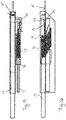
- Figure 4 shows schematically a side view of the tool 10 shown in Figure 3 , also seen from the side where the magazine is positioned, where Figure 4 also shows the starting point in the process of separating the first clamp from the remaining clamps 12. Due of the shape of the clamp separating device13, the contact surface and the force applied to the clamps 12 in the magazine by the rider 18, ref. the arrow F in Figure 4 , the first clamp 12' will be pressed against the inclined surface 19 in the clamp separating device 13.
- the force F, acting on the rider 18, is produced by a spring (not shown) that extends between the movable rider 18 on the one side and the rear end of the housing, so that when a filled up magazine 11 is inserted into the tool 10, the spring will be compressed and thus produce the required force F on the rider 18.
- the result is that the leg or legs 1 on the first clamp 12' will be tilted upwards into contact with the lower surface 20 on the clamp separating device 13, so that the tailpiece 14, which is subjected to a force F in a direction towards the second clamp 12.
- the second clamp 12 is locked against movement and the first clap 12' will be completely freed from the remaining clamps 12 in the magazine 11, so that the first clamp 12' now can be moved into the barrel bore 16.
- Figure 6 shows the same view as shown in the Figures above.
- the first clamp 12' is now separated from the remaining, consecutive clamps 12 in the magazine 11, the force from the tailpiece 14, forcing these backwards and holding them in locked position.
- the first clamp 12' that is allowed to be brought further into the barrel or bore, which now is open and accessible, since the ramming bolt 17 is retracted to its extreme inner position in the barrel or bore 16.
- the head edge of the first clamp 12' rests against the skewed surface 19 on the clamp separating device 13, while the opposite surface of the head rests against the lower edge of the clamp separating device 13. Hence, the first clamp 12' is tilted up towards the skewed surface 20 below the clamp separating device 13.
- Figure 7 shows schematically a view of parts of the tool 10, seen fro above, where the first clamp 12' is about to be transferred from the clamp separating device 13 and into the bore 16.
- the first clamp 12' is freed from the remaining clamps 12 and is exposed to a force F in transverse or sideways direction, so that the first clamp 12' may be transferred into the barrel or bore 16.
- This sideways acting force F may for example be provided by one or more magnets (not shown) arranged on opposite wall in the barrel or bore 16.
- both the tailpiece 14 and the ramming bolt 17 are retracted to their one extreme position, so that free access is provided for the first clamp into the barrel or bore in a position in front of the ramming bolt 17.
- the tailpiece 14 applies in this position still a force on the second and the remaining clamps 12, so that these thus are prevented from movement into the barrel or bore 16 and in this way causes jamming of two or more clamps 12 in the barrel or bore 16.
- the bottom surface in the barrel or bore i.e. the surface on which the clamp 12' resting, may be provided with one or more small magnet (not shown), holding the first clamp 12' in the shown position.
- Figure 8 shows schematically a view seen from above of parts of the tool 10, where the first clamp 12' is in position in the barrel or bore, ready for being forced into the supporting surface.
- the ramming bolt 17 By ramming the free end of the ramming bolt 17, for example by means of a hammer (not shown), the ramming bolt will move forward in the barrel or bore 17.
- the tailpiece 14 When the front of the ramming bolt has moved past the opening of the clamp separating device 13, the tailpiece 14 will be subjected to a force F (ref. Figure 9 ) moving the tailpiece 14 back to its starting position, ref. Figure 2 or Figure 10 .
- Figures 9 and 10 show schematically a view seen from above and from the side of the tool respectively, where the first clamp is in its outmost position in the barrel or bore, about to be rammed into the supporting surface, the tailpiece being subjected to a force F moving the tailpiece 14 back to its extreme second position, ready for a new separation of the a new first clamp.
- Figure 12 shows schematically a cross section and a view respectively of a suitable embodiment of a magazine 11 configured to contain for example clamps, for example of the types of clamps 12, shown in Figures 1a to 1d .
- the magazine shown 11 has a more or less U-shape with a top 22 and two from the top outwards projecting legs 23.
- a recess 24 is arranged on each side, extending along the entire length of the magazine11. Said recesses 24 contribute to a more sideways movability of the legs 23 during insertion of new clamps 12 into the magazine 11.
- the legs 23 are on their inner surface provided with one or more beads 25 facing inwards towards each other. The purpose of the beads 24 is to contribute to retaining the loaded clamps 12 in the magazine. If the clamps are provided with only one leg 1 the clamps will be arranged with their legs pointed skewed out of the U-shaped magazine.
- the clamps 12 are provided with three legs the two outer legs will be arranged inside the legs 23 on the magazine 11.
- the bottom 26 of the magazine 11 will face downwards with the legs 1 of the clamps 12 facing outwards from the magazine 11, while the clamp heads 2 will be positioned inside the magazine.
- the magazine legs 23 will press against the heads 2 of the clamps 12, keeping the clamps in a locked position.
- the legs 23 of the magazine is pressed outwards and the clamps 12 will be freed from the magazine.
Landscapes
- Physics & Mathematics (AREA)
- Geometry (AREA)
- Engineering & Computer Science (AREA)
- Mechanical Engineering (AREA)
- Gripping On Spindles (AREA)
- Portable Nailing Machines And Staplers (AREA)
- Details Of Garments (AREA)
- Inorganic Insulating Materials (AREA)
Priority Applications (1)
| Application Number | Priority Date | Filing Date | Title |
|---|---|---|---|
| EP19174819.3A EP3560659B1 (fr) | 2013-04-17 | 2014-04-11 | Outil de serrage multi-magazine |
Applications Claiming Priority (2)
| Application Number | Priority Date | Filing Date | Title |
|---|---|---|---|
| NO20130523A NO337036B1 (no) | 2013-04-17 | 2013-04-17 | Verktøy og fremgangsmåte for innfesting av klammer på et underlag |
| EP14164413.8A EP2792453B1 (fr) | 2013-04-17 | 2014-04-11 | Outil de serrage à plusiers réservoirs |
Related Parent Applications (2)
| Application Number | Title | Priority Date | Filing Date |
|---|---|---|---|
| EP14164413.8A Division EP2792453B1 (fr) | 2013-04-17 | 2014-04-11 | Outil de serrage à plusiers réservoirs |
| EP14164413.8A Division-Into EP2792453B1 (fr) | 2013-04-17 | 2014-04-11 | Outil de serrage à plusiers réservoirs |
Related Child Applications (2)
| Application Number | Title | Priority Date | Filing Date |
|---|---|---|---|
| EP19174819.3A Division-Into EP3560659B1 (fr) | 2013-04-17 | 2014-04-11 | Outil de serrage multi-magazine |
| EP19174819.3A Division EP3560659B1 (fr) | 2013-04-17 | 2014-04-11 | Outil de serrage multi-magazine |
Publications (2)
| Publication Number | Publication Date |
|---|---|
| EP3345727A1 true EP3345727A1 (fr) | 2018-07-11 |
| EP3345727B1 EP3345727B1 (fr) | 2021-03-17 |
Family
ID=50473179
Family Applications (3)
| Application Number | Title | Priority Date | Filing Date |
|---|---|---|---|
| EP18154402.4A Active EP3345727B1 (fr) | 2013-04-17 | 2014-04-11 | Outil de serrage multi-magazine |
| EP19174819.3A Active EP3560659B1 (fr) | 2013-04-17 | 2014-04-11 | Outil de serrage multi-magazine |
| EP14164413.8A Active EP2792453B1 (fr) | 2013-04-17 | 2014-04-11 | Outil de serrage à plusiers réservoirs |
Family Applications After (2)
| Application Number | Title | Priority Date | Filing Date |
|---|---|---|---|
| EP19174819.3A Active EP3560659B1 (fr) | 2013-04-17 | 2014-04-11 | Outil de serrage multi-magazine |
| EP14164413.8A Active EP2792453B1 (fr) | 2013-04-17 | 2014-04-11 | Outil de serrage à plusiers réservoirs |
Country Status (2)
| Country | Link |
|---|---|
| EP (3) | EP3345727B1 (fr) |
| NO (1) | NO337036B1 (fr) |
Families Citing this family (2)
| Publication number | Priority date | Publication date | Assignee | Title |
|---|---|---|---|---|
| US10814465B2 (en) | 2016-03-22 | 2020-10-27 | Stanley Black & Decker, Inc. | Safety device for tackers |
| NO347225B1 (en) * | 2021-11-15 | 2023-07-10 | Letti As | Clip hammer |
Citations (7)
| Publication number | Priority date | Publication date | Assignee | Title |
|---|---|---|---|---|
| US2775763A (en) * | 1954-08-25 | 1957-01-01 | Bell Telephone Labor Inc | Stapling machine |
| NO120277B (fr) * | 1967-05-08 | 1970-09-28 | S Abrahamsen | |
| US3633811A (en) * | 1969-02-18 | 1972-01-11 | Behrens Friedrich Joh | Apparatus to drive various fastening means |
| US5695108A (en) * | 1996-03-05 | 1997-12-09 | De Poan Pneumatic Corporation | Magazine system of a stapler |
| JPH1148159A (ja) * | 1997-08-11 | 1999-02-23 | Satoharu Takahashi | コード用ステープラー |
| EP1445072A1 (fr) * | 2003-02-07 | 2004-08-11 | HILTI Aktiengesellschaft | Guidage de moyens de fixation |
| EP1745892A2 (fr) * | 2005-07-18 | 2007-01-24 | Thor Gunnar Pettersen | Outil pour fixer des pinces sur une surface porteuse |
-
2013
- 2013-04-17 NO NO20130523A patent/NO337036B1/no unknown
-
2014
- 2014-04-11 EP EP18154402.4A patent/EP3345727B1/fr active Active
- 2014-04-11 EP EP19174819.3A patent/EP3560659B1/fr active Active
- 2014-04-11 EP EP14164413.8A patent/EP2792453B1/fr active Active
Patent Citations (7)
| Publication number | Priority date | Publication date | Assignee | Title |
|---|---|---|---|---|
| US2775763A (en) * | 1954-08-25 | 1957-01-01 | Bell Telephone Labor Inc | Stapling machine |
| NO120277B (fr) * | 1967-05-08 | 1970-09-28 | S Abrahamsen | |
| US3633811A (en) * | 1969-02-18 | 1972-01-11 | Behrens Friedrich Joh | Apparatus to drive various fastening means |
| US5695108A (en) * | 1996-03-05 | 1997-12-09 | De Poan Pneumatic Corporation | Magazine system of a stapler |
| JPH1148159A (ja) * | 1997-08-11 | 1999-02-23 | Satoharu Takahashi | コード用ステープラー |
| EP1445072A1 (fr) * | 2003-02-07 | 2004-08-11 | HILTI Aktiengesellschaft | Guidage de moyens de fixation |
| EP1745892A2 (fr) * | 2005-07-18 | 2007-01-24 | Thor Gunnar Pettersen | Outil pour fixer des pinces sur une surface porteuse |
Also Published As
| Publication number | Publication date |
|---|---|
| EP2792453A3 (fr) | 2015-05-27 |
| EP2792453A2 (fr) | 2014-10-22 |
| NO337036B1 (no) | 2016-01-04 |
| EP3345727B1 (fr) | 2021-03-17 |
| NO20130523A1 (no) | 2014-10-20 |
| EP2792453B1 (fr) | 2018-10-10 |
| EP3560659A1 (fr) | 2019-10-30 |
| EP3560659B1 (fr) | 2022-01-26 |
Similar Documents
| Publication | Publication Date | Title |
|---|---|---|
| US6499642B1 (en) | Magazine mechanism for nailing machine | |
| US4367837A (en) | Tape magazine feed apparatus for head driven fasteners | |
| US20250314343A1 (en) | Cable puller and method | |
| US6476339B2 (en) | Stud welding gun | |
| US6398169B1 (en) | Device for securing longitudinal elements on a panel and tool for installing the same | |
| US3743159A (en) | Cartridge-actuated fastener-driving tools | |
| EP3345727B1 (fr) | Outil de serrage multi-magazine | |
| SE1151012A1 (sv) | Takklammermonteringsverktyg med remsformigt takmonteringsklammermagasin, samt takfogsklammer | |
| US3212535A (en) | Jamming feature | |
| KR102449678B1 (ko) | 판지 코일 보호기 시스템 | |
| US5400941A (en) | Core end sleeves which are linked to one another in the form of a belt, and device for their transportation | |
| JP5951337B2 (ja) | せん断装置およびせん断方法 | |
| US3025594A (en) | Apparatus for assembling helical springs on objects | |
| JPS5973901A (ja) | 自動釘打装置におけるステ−プル自動装填装置 | |
| EP0523218B1 (fr) | Pont utilisé avec une agrafe dans une agrafeuse | |
| US3026518A (en) | Automatic stapler | |
| JP3622199B2 (ja) | 連結釘用釘打機における釘供給機構 | |
| KR20180000363A (ko) | 고무튜브 삽입장치 | |
| JP3622198B2 (ja) | 連結釘用釘打機における釘供給機構 | |
| NO20151359A1 (no) | Verktøy og fremgangsmåte for innfesting av klammer på et underlag | |
| CN220882205U (zh) | 枪钉钉匣及地板枪 | |
| JP2641008B2 (ja) | ミシンの下糸ボビンケースの自動取出方法 | |
| CN210414411U (zh) | 一种c型钉枪 | |
| NO20150197A1 (no) | Magasin til klammerverktøy | |
| JPS6240778Y2 (fr) |
Legal Events
| Date | Code | Title | Description |
|---|---|---|---|
| PUAI | Public reference made under article 153(3) epc to a published international application that has entered the european phase |
Free format text: ORIGINAL CODE: 0009012 |
|
| STAA | Information on the status of an ep patent application or granted ep patent |
Free format text: STATUS: THE APPLICATION HAS BEEN PUBLISHED |
|
| AC | Divisional application: reference to earlier application |
Ref document number: 2792453 Country of ref document: EP Kind code of ref document: P |
|
| AK | Designated contracting states |
Kind code of ref document: A1 Designated state(s): AL AT BE BG CH CY CZ DE DK EE ES FI FR GB GR HR HU IE IS IT LI LT LU LV MC MK MT NL NO PL PT RO RS SE SI SK SM TR |
|
| STAA | Information on the status of an ep patent application or granted ep patent |
Free format text: STATUS: REQUEST FOR EXAMINATION WAS MADE |
|
| 17P | Request for examination filed |
Effective date: 20190111 |
|
| RBV | Designated contracting states (corrected) |
Designated state(s): AL AT BE BG CH CY CZ DE DK EE ES FI FR GB GR HR HU IE IS IT LI LT LU LV MC MK MT NL NO PL PT RO RS SE SI SK SM TR |
|
| STAA | Information on the status of an ep patent application or granted ep patent |
Free format text: STATUS: EXAMINATION IS IN PROGRESS |
|
| 17Q | First examination report despatched |
Effective date: 20190315 |
|
| RIC1 | Information provided on ipc code assigned before grant |
Ipc: H02G 3/32 20060101ALN20201006BHEP Ipc: B25C 5/16 20060101ALI20201006BHEP Ipc: B25C 5/00 20060101AFI20201006BHEP |
|
| GRAP | Despatch of communication of intention to grant a patent |
Free format text: ORIGINAL CODE: EPIDOSNIGR1 |
|
| STAA | Information on the status of an ep patent application or granted ep patent |
Free format text: STATUS: GRANT OF PATENT IS INTENDED |
|
| INTG | Intention to grant announced |
Effective date: 20201116 |
|
| GRAS | Grant fee paid |
Free format text: ORIGINAL CODE: EPIDOSNIGR3 |
|
| GRAA | (expected) grant |
Free format text: ORIGINAL CODE: 0009210 |
|
| STAA | Information on the status of an ep patent application or granted ep patent |
Free format text: STATUS: THE PATENT HAS BEEN GRANTED |
|
| AC | Divisional application: reference to earlier application |
Ref document number: 2792453 Country of ref document: EP Kind code of ref document: P |
|
| AK | Designated contracting states |
Kind code of ref document: B1 Designated state(s): AL AT BE BG CH CY CZ DE DK EE ES FI FR GB GR HR HU IE IS IT LI LT LU LV MC MK MT NL NO PL PT RO RS SE SI SK SM TR |
|
| REG | Reference to a national code |
Ref country code: GB Ref legal event code: FG4D |
|
| REG | Reference to a national code |
Ref country code: CH Ref legal event code: EP |
|
| REG | Reference to a national code |
Ref country code: DE Ref legal event code: R096 Ref document number: 602014075875 Country of ref document: DE |
|
| REG | Reference to a national code |
Ref country code: IE Ref legal event code: FG4D |
|
| REG | Reference to a national code |
Ref country code: AT Ref legal event code: REF Ref document number: 1371806 Country of ref document: AT Kind code of ref document: T Effective date: 20210415 |
|
| REG | Reference to a national code |
Ref country code: NO Ref legal event code: T2 Effective date: 20210317 |
|
| REG | Reference to a national code |
Ref country code: SE Ref legal event code: TRGR |
|
| REG | Reference to a national code |
Ref country code: LT Ref legal event code: MG9D |
|
| PG25 | Lapsed in a contracting state [announced via postgrant information from national office to epo] |
Ref country code: BG Free format text: LAPSE BECAUSE OF FAILURE TO SUBMIT A TRANSLATION OF THE DESCRIPTION OR TO PAY THE FEE WITHIN THE PRESCRIBED TIME-LIMIT Effective date: 20210617 Ref country code: HR Free format text: LAPSE BECAUSE OF FAILURE TO SUBMIT A TRANSLATION OF THE DESCRIPTION OR TO PAY THE FEE WITHIN THE PRESCRIBED TIME-LIMIT Effective date: 20210317 Ref country code: GR Free format text: LAPSE BECAUSE OF FAILURE TO SUBMIT A TRANSLATION OF THE DESCRIPTION OR TO PAY THE FEE WITHIN THE PRESCRIBED TIME-LIMIT Effective date: 20210618 Ref country code: FI Free format text: LAPSE BECAUSE OF FAILURE TO SUBMIT A TRANSLATION OF THE DESCRIPTION OR TO PAY THE FEE WITHIN THE PRESCRIBED TIME-LIMIT Effective date: 20210317 |
|
| REG | Reference to a national code |
Ref country code: AT Ref legal event code: MK05 Ref document number: 1371806 Country of ref document: AT Kind code of ref document: T Effective date: 20210317 |
|
| REG | Reference to a national code |
Ref country code: NL Ref legal event code: MP Effective date: 20210317 |
|
| PG25 | Lapsed in a contracting state [announced via postgrant information from national office to epo] |
Ref country code: RS Free format text: LAPSE BECAUSE OF FAILURE TO SUBMIT A TRANSLATION OF THE DESCRIPTION OR TO PAY THE FEE WITHIN THE PRESCRIBED TIME-LIMIT Effective date: 20210317 Ref country code: LV Free format text: LAPSE BECAUSE OF FAILURE TO SUBMIT A TRANSLATION OF THE DESCRIPTION OR TO PAY THE FEE WITHIN THE PRESCRIBED TIME-LIMIT Effective date: 20210317 |
|
| PG25 | Lapsed in a contracting state [announced via postgrant information from national office to epo] |
Ref country code: NL Free format text: LAPSE BECAUSE OF FAILURE TO SUBMIT A TRANSLATION OF THE DESCRIPTION OR TO PAY THE FEE WITHIN THE PRESCRIBED TIME-LIMIT Effective date: 20210317 |
|
| PG25 | Lapsed in a contracting state [announced via postgrant information from national office to epo] |
Ref country code: LT Free format text: LAPSE BECAUSE OF FAILURE TO SUBMIT A TRANSLATION OF THE DESCRIPTION OR TO PAY THE FEE WITHIN THE PRESCRIBED TIME-LIMIT Effective date: 20210317 Ref country code: CZ Free format text: LAPSE BECAUSE OF FAILURE TO SUBMIT A TRANSLATION OF THE DESCRIPTION OR TO PAY THE FEE WITHIN THE PRESCRIBED TIME-LIMIT Effective date: 20210317 Ref country code: EE Free format text: LAPSE BECAUSE OF FAILURE TO SUBMIT A TRANSLATION OF THE DESCRIPTION OR TO PAY THE FEE WITHIN THE PRESCRIBED TIME-LIMIT Effective date: 20210317 Ref country code: SM Free format text: LAPSE BECAUSE OF FAILURE TO SUBMIT A TRANSLATION OF THE DESCRIPTION OR TO PAY THE FEE WITHIN THE PRESCRIBED TIME-LIMIT Effective date: 20210317 Ref country code: AT Free format text: LAPSE BECAUSE OF FAILURE TO SUBMIT A TRANSLATION OF THE DESCRIPTION OR TO PAY THE FEE WITHIN THE PRESCRIBED TIME-LIMIT Effective date: 20210317 |
|
| REG | Reference to a national code |
Ref country code: DE Ref legal event code: R119 Ref document number: 602014075875 Country of ref document: DE |
|
| PG25 | Lapsed in a contracting state [announced via postgrant information from national office to epo] |
Ref country code: SK Free format text: LAPSE BECAUSE OF FAILURE TO SUBMIT A TRANSLATION OF THE DESCRIPTION OR TO PAY THE FEE WITHIN THE PRESCRIBED TIME-LIMIT Effective date: 20210317 Ref country code: RO Free format text: LAPSE BECAUSE OF FAILURE TO SUBMIT A TRANSLATION OF THE DESCRIPTION OR TO PAY THE FEE WITHIN THE PRESCRIBED TIME-LIMIT Effective date: 20210317 Ref country code: PT Free format text: LAPSE BECAUSE OF FAILURE TO SUBMIT A TRANSLATION OF THE DESCRIPTION OR TO PAY THE FEE WITHIN THE PRESCRIBED TIME-LIMIT Effective date: 20210719 Ref country code: PL Free format text: LAPSE BECAUSE OF FAILURE TO SUBMIT A TRANSLATION OF THE DESCRIPTION OR TO PAY THE FEE WITHIN THE PRESCRIBED TIME-LIMIT Effective date: 20210317 Ref country code: IS Free format text: LAPSE BECAUSE OF FAILURE TO SUBMIT A TRANSLATION OF THE DESCRIPTION OR TO PAY THE FEE WITHIN THE PRESCRIBED TIME-LIMIT Effective date: 20210717 |
|
| PG25 | Lapsed in a contracting state [announced via postgrant information from national office to epo] |
Ref country code: LU Free format text: LAPSE BECAUSE OF NON-PAYMENT OF DUE FEES Effective date: 20210411 |
|
| REG | Reference to a national code |
Ref country code: BE Ref legal event code: MM Effective date: 20210430 |
|
| PLBE | No opposition filed within time limit |
Free format text: ORIGINAL CODE: 0009261 |
|
| STAA | Information on the status of an ep patent application or granted ep patent |
Free format text: STATUS: NO OPPOSITION FILED WITHIN TIME LIMIT |
|
| PG25 | Lapsed in a contracting state [announced via postgrant information from national office to epo] |
Ref country code: ES Free format text: LAPSE BECAUSE OF FAILURE TO SUBMIT A TRANSLATION OF THE DESCRIPTION OR TO PAY THE FEE WITHIN THE PRESCRIBED TIME-LIMIT Effective date: 20210317 Ref country code: MC Free format text: LAPSE BECAUSE OF FAILURE TO SUBMIT A TRANSLATION OF THE DESCRIPTION OR TO PAY THE FEE WITHIN THE PRESCRIBED TIME-LIMIT Effective date: 20210317 Ref country code: AL Free format text: LAPSE BECAUSE OF FAILURE TO SUBMIT A TRANSLATION OF THE DESCRIPTION OR TO PAY THE FEE WITHIN THE PRESCRIBED TIME-LIMIT Effective date: 20210317 Ref country code: DE Free format text: LAPSE BECAUSE OF NON-PAYMENT OF DUE FEES Effective date: 20211103 Ref country code: DK Free format text: LAPSE BECAUSE OF FAILURE TO SUBMIT A TRANSLATION OF THE DESCRIPTION OR TO PAY THE FEE WITHIN THE PRESCRIBED TIME-LIMIT Effective date: 20210317 Ref country code: CH Free format text: LAPSE BECAUSE OF NON-PAYMENT OF DUE FEES Effective date: 20210430 Ref country code: LI Free format text: LAPSE BECAUSE OF NON-PAYMENT OF DUE FEES Effective date: 20210430 |
|
| 26N | No opposition filed |
Effective date: 20211220 |
|
| GBPC | Gb: european patent ceased through non-payment of renewal fee |
Effective date: 20210617 |
|
| PG25 | Lapsed in a contracting state [announced via postgrant information from national office to epo] |
Ref country code: SI Free format text: LAPSE BECAUSE OF FAILURE TO SUBMIT A TRANSLATION OF THE DESCRIPTION OR TO PAY THE FEE WITHIN THE PRESCRIBED TIME-LIMIT Effective date: 20210317 |
|
| PG25 | Lapsed in a contracting state [announced via postgrant information from national office to epo] |
Ref country code: IT Free format text: LAPSE BECAUSE OF FAILURE TO SUBMIT A TRANSLATION OF THE DESCRIPTION OR TO PAY THE FEE WITHIN THE PRESCRIBED TIME-LIMIT Effective date: 20210317 Ref country code: IE Free format text: LAPSE BECAUSE OF NON-PAYMENT OF DUE FEES Effective date: 20210411 Ref country code: GB Free format text: LAPSE BECAUSE OF NON-PAYMENT OF DUE FEES Effective date: 20210617 |
|
| PG25 | Lapsed in a contracting state [announced via postgrant information from national office to epo] |
Ref country code: IS Free format text: LAPSE BECAUSE OF FAILURE TO SUBMIT A TRANSLATION OF THE DESCRIPTION OR TO PAY THE FEE WITHIN THE PRESCRIBED TIME-LIMIT Effective date: 20210717 Ref country code: FR Free format text: LAPSE BECAUSE OF NON-PAYMENT OF DUE FEES Effective date: 20210517 |
|
| PG25 | Lapsed in a contracting state [announced via postgrant information from national office to epo] |
Ref country code: BE Free format text: LAPSE BECAUSE OF NON-PAYMENT OF DUE FEES Effective date: 20210430 |
|
| PG25 | Lapsed in a contracting state [announced via postgrant information from national office to epo] |
Ref country code: CY Free format text: LAPSE BECAUSE OF FAILURE TO SUBMIT A TRANSLATION OF THE DESCRIPTION OR TO PAY THE FEE WITHIN THE PRESCRIBED TIME-LIMIT Effective date: 20210317 |
|
| PG25 | Lapsed in a contracting state [announced via postgrant information from national office to epo] |
Ref country code: HU Free format text: LAPSE BECAUSE OF FAILURE TO SUBMIT A TRANSLATION OF THE DESCRIPTION OR TO PAY THE FEE WITHIN THE PRESCRIBED TIME-LIMIT; INVALID AB INITIO Effective date: 20140411 |
|
| PG25 | Lapsed in a contracting state [announced via postgrant information from national office to epo] |
Ref country code: MK Free format text: LAPSE BECAUSE OF FAILURE TO SUBMIT A TRANSLATION OF THE DESCRIPTION OR TO PAY THE FEE WITHIN THE PRESCRIBED TIME-LIMIT Effective date: 20210317 |
|
| PG25 | Lapsed in a contracting state [announced via postgrant information from national office to epo] |
Ref country code: MT Free format text: LAPSE BECAUSE OF FAILURE TO SUBMIT A TRANSLATION OF THE DESCRIPTION OR TO PAY THE FEE WITHIN THE PRESCRIBED TIME-LIMIT Effective date: 20210317 |
|
| PG25 | Lapsed in a contracting state [announced via postgrant information from national office to epo] |
Ref country code: TR Free format text: LAPSE BECAUSE OF FAILURE TO SUBMIT A TRANSLATION OF THE DESCRIPTION OR TO PAY THE FEE WITHIN THE PRESCRIBED TIME-LIMIT Effective date: 20210317 |
|
| PGFP | Annual fee paid to national office [announced via postgrant information from national office to epo] |
Ref country code: SE Payment date: 20260312 Year of fee payment: 13 |
|
| PGFP | Annual fee paid to national office [announced via postgrant information from national office to epo] |
Ref country code: NO Payment date: 20260211 Year of fee payment: 13 |