EP1445072A1 - Guidage de moyens de fixation - Google Patents
Guidage de moyens de fixation Download PDFInfo
- Publication number
- EP1445072A1 EP1445072A1 EP04100428A EP04100428A EP1445072A1 EP 1445072 A1 EP1445072 A1 EP 1445072A1 EP 04100428 A EP04100428 A EP 04100428A EP 04100428 A EP04100428 A EP 04100428A EP 1445072 A1 EP1445072 A1 EP 1445072A1
- Authority
- EP
- European Patent Office
- Prior art keywords
- magazine strip
- guide
- opening
- driving tool
- fastener guide
- Prior art date
- Legal status (The legal status is an assumption and is not a legal conclusion. Google has not performed a legal analysis and makes no representation as to the accuracy of the status listed.)
- Granted
Links
Images




Classifications
-
- B—PERFORMING OPERATIONS; TRANSPORTING
- B25—HAND TOOLS; PORTABLE POWER-DRIVEN TOOLS; MANIPULATORS
- B25B—TOOLS OR BENCH DEVICES NOT OTHERWISE PROVIDED FOR, FOR FASTENING, CONNECTING, DISENGAGING, OR HOLDING
- B25B23/00—Details of, or accessories for, spanners, wrenches, screwdrivers
- B25B23/02—Arrangements for handling screws or nuts
- B25B23/04—Arrangements for handling screws or nuts for feeding screws or nuts
- B25B23/06—Arrangements for handling screws or nuts for feeding screws or nuts using built-in magazine
-
- B—PERFORMING OPERATIONS; TRANSPORTING
- B25—HAND TOOLS; PORTABLE POWER-DRIVEN TOOLS; MANIPULATORS
- B25C—HAND-HELD NAILING OR STAPLING TOOLS; MANUALLY OPERATED PORTABLE STAPLING TOOLS
- B25C5/00—Manually operated portable stapling tools; Hand-held power-operated stapling tools; Staple feeding devices therefor
- B25C5/16—Staple-feeding devices, e.g. with feeding means, supports for staples or accessories concerning feeding devices
- B25C5/1606—Feeding means
- B25C5/1634—Feeding means employing gravity feed
Definitions
- the invention relates to a fastener guide for use on a power operated Driver, in particular a stand-up tool, which has a guide path, in which several fasteners can be received and the one device-side opening and has a free opening, the guide path coming from the free opening has a curvature to the device-side opening.
- Stand-up tools are primarily used for the assembly of floor-side or walk-in Workpieces, such as flat roofs, with the operator at the Assembly can maintain a largely upright posture.
- the driving tool is filled with fasteners with the help of of magazine strips in which the fasteners are kept in stock. These magazine strips are mostly essentially parallel to the working direction of the driving tool attached to the fastener guide. The fasteners slip the magazine strip into the fastener guide of the tacker, which then directs its curvature to the tacker.
- DE 33 25 565 shows a magazine hand screwdriver with a magazine holder in which a Magazine strips can be inserted and which can be closed by a closure hood is.
- the fasteners slide out of it in a curved screw guide, which fasteners a screwing tool feeds.
- the present invention has for its object to provide a fastener guide, which avoids the aforementioned disadvantages and a quick filling of a powered driving tool guaranteed.
- the object is achieved in that the fastener guide Via connection means, such as quick connection means of a tool release Connection, for example in the form of a snap or snap connection or a bayonet lock, can be releasably attached to the driving tool and the guide path has a fall-out protection device at both openings.
- connection means such as quick connection means of a tool release Connection, for example in the form of a snap or snap connection or a bayonet lock
- the fastener guide for more convenient filling of the driving tool, or the stand-up tool.
- the fallout protection devices prevent fasteners still contained in the fastener guide, such as screws or bolts, when removing the fastener guide can accidentally fall out of the tacker at an opening.
- At least one of the fall protection devices is a blocking element has in the closed position of the fall protection device in the guide path protrudes and thus blocks the guide path. This makes it more cost-effective but also ensure safe protection against falling out.
- the blocking element of the fall protection device is preferably on the device side Opening when attaching the fastener guide to the driving tool from the guide path spent and thus occupies an open position. This is done in a simple manner ensures that the fasteners are in the attached state of the fastener guide can get into the tacker unhindered.
- the fastener guide on one of the Open a magazine strip opening device Through such a magazine strip opening device on the fastener guide can be on a holder for magazine strips on the driving tool. Rather, the fastener guide can be carried out that the driving tool with attached fastener guide overall has a compact shape and is therefore easy to handle in operation.
- the filling with fasteners can still be done through usual magazine strips, which, however, are no longer attached to the tacker, but rather through the magazine strip opening device be opened and d abei their fasteners in the Submit fastener guide.
- the fastener guide can be filled both in the attached and in the released state opposite the fastener guide the driving tool.
- the magazine strip opening device preferably has a deflection device. This protrudes into a magazine strip holder into which a magazine strip is inserted can be. When inserting the magazine strip into the magazine strip holder at least one wall of the magazine strip at least through the deflection device partially bent or deflected away from the rest of the magazine strip. This Arrangement of a deflection device in a magazine strip holder ensures one Safe and quick opening of the magazine strip and easy filling of the fastener guide.
- the fall protection device instructs the opening the magazine strip opening device is arranged on a spring arm. That spring arm can be pivoted through the deflected wall. This makes it easier to do Way an opening of the magazine strip with simultaneous unlocking of the fall protection device achieve, whereby the manufacturing costs can be kept relatively low.
- the deflection device advantageously has at least two inclined areas which each in an insertion direction of the magazine strip from the magazine strip holder are inclined away and point towards an inner side of the spring arm, whereby a simple and safe displacement of the fall protection device into an open position is guaranteed.
- the locking element is formed on the inside of the spring arm is and has an inclined contact surface in the direction of the magazine strip receptacle.
- the inclined contact surface enables a uniform adjustment of the fall protection device through the wall end of the magazine strip and thus a trouble-free Opening of the guide path opposite the magazine strip.
- the magazine strip opening device is preferably arranged at the free opening, whereby a filling of the fastener guide can also take place when it is with the tacker is connected.
- the connecting means has, which is complementary to the connecting means of the fastener guide are formed.
- the spring arm of the fall protection device on the device side Opening has an actuator. Presses against the actuator Attaching the fastener guide a deflection element formed on the driving tool. In this way, the spring arm is pivoted and the locking element out of the guide path emotional.
- a fall-out protection device is provided, which is formed by the simplest on the driving tool Deflection elements, such as exposed areas or recesses sloping surfaces formed on it, can be opened. This can reduce the manufacturing costs can be further minimized.
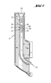
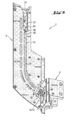
- FIG. 1 shows a stand-up tool 2 which has a power-driven driving tool 4, on which a fastener guide 6 is attached.
- the driving tool 4 and the fastener guide 6 are detachably connected to one another via a connection area 8, on which the driving tool 4 and the fastener guide 6 connecting means Tool-free quick connection device in the form of a locking device.
- the fastener guide 6 has a guide 10, in the heads 12 of fasteners 14, such as screws or bolts, are slidably held.
- the space that the fasteners 14 move along the guide 10 traversing is referred to as guide path 16.
- the guide path 16 has an opening 18 on the device side and a free opening 20.
- a first fall protection device 26 is provided, the first Has spring arm 28 which is connected at one end to the fastener guide 6 is.
- the first spring arm 28 has a first nose-shaped one Locking element 30.
- This first blocking element forms in the direction of the magazine strip receptacle 22 30 an inclined contact surface 32.
- the first spring arm 28 projects the first blocking element 30 into the guide path 16 and thus blocks it in the direction of the receiving opening 24. This prevents fastening means 14 which are arranged in the guide path 16 of the fastener guide 6, unintentionally from the Slip out opening 24.
- a magazine strip opening device at the free opening 20 of the guide path 16 34 arranged.
- This essentially consists of a jagged deflection device 36, which is formed on a wall opening 38 of the fastener guide 6 and has a bevel 40 which projects into and from the magazine strip receptacle 22 this is directed outwards in the direction of the first locking element 30.
- 3 to 5 show how the fastener guide 6 through a magazine strip 42 is filled, the funnel-shaped receiving opening 24 into the magazine strip receptacle 22 is pushed.
- Fig. 3 shows the starting position with a closed first fall protection device 26, which is a fastener 14 already guided in the guide path 16 by means of the first Blocking element blocked in the direction of the magazine strip receptacle 22.
- the magazine strip 42 protrudes into the magazine strip receptacle 22 and has a front end region 44 in which a receiving cross section 43 of the magazine strip 42 is narrowed in this way that fastener heads (not shown) held in the receiving cross section cannot accidentally slip out of the magazine strip.
- On two upper walls 45 a deflection body 46 is formed in each case, which extends from the end region 44 upwards projects.
- a deflection element 58 in the form of a housing recess is formed on the driving tool 4 (see Fig. 6).
- the actuating element 54 in the deflection element 58 engages the actuating element 54 in the deflection element 58.
- the contact surface comes here 56 in contact with the deflection element 58, whereby the spring arm 52 is pressed to the side.
- the second locking element 50 is moved out of the guide path 16.
- FIG. 7 shows an alternative embodiment in which the actuating element 54 for Locking element 50 is formed spaced apart. In this position, the second fall protection device 48 can fasteners 14 guided in the fastener guide 6 now slip into the driving tool 4 for assembly.
- first fall protection device 26, the second fall protection device 48 as well as the magazine strip opening device 34 in each case is formed in pairs, even if only a simple one for illustrative reasons Training is shown.
Landscapes
- Engineering & Computer Science (AREA)
- Mechanical Engineering (AREA)
- Portable Nailing Machines And Staplers (AREA)
Applications Claiming Priority (2)
| Application Number | Priority Date | Filing Date | Title |
|---|---|---|---|
| DE10305043A DE10305043A1 (de) | 2003-02-07 | 2003-02-07 | Befestigungsmittelführung |
| DE10305043 | 2003-02-07 |
Publications (2)
| Publication Number | Publication Date |
|---|---|
| EP1445072A1 true EP1445072A1 (fr) | 2004-08-11 |
| EP1445072B1 EP1445072B1 (fr) | 2008-11-26 |
Family
ID=32603194
Family Applications (1)
| Application Number | Title | Priority Date | Filing Date |
|---|---|---|---|
| EP04100428A Expired - Lifetime EP1445072B1 (fr) | 2003-02-07 | 2004-02-05 | Guidage de moyens de fixation |
Country Status (3)
| Country | Link |
|---|---|
| US (1) | US6978698B2 (fr) |
| EP (1) | EP1445072B1 (fr) |
| DE (2) | DE10305043A1 (fr) |
Cited By (3)
| Publication number | Priority date | Publication date | Assignee | Title |
|---|---|---|---|---|
| EP2792453A3 (fr) * | 2013-04-17 | 2015-05-27 | Thor Gunnar Pettersen | outil de serrage à plusiers réservoirs |
| CN104723054A (zh) * | 2013-12-19 | 2015-06-24 | 致伸科技股份有限公司 | 弹匣式螺丝锁固装置及螺丝补充装置 |
| EP4534249A1 (fr) | 2023-10-02 | 2025-04-09 | SFS Group International AG | Appareil de pose |
Families Citing this family (5)
| Publication number | Priority date | Publication date | Assignee | Title |
|---|---|---|---|---|
| AU155884S (en) * | 2003-08-29 | 2004-07-14 | Bosch Gmbh Robert | Impact drilling machine |
| US20080105726A1 (en) * | 2006-10-18 | 2008-05-08 | Malco Products, Inc. | Vertical feed hand stapler |
| DE102008060476B4 (de) * | 2008-02-05 | 2013-03-07 | Heiko Schmidt | Vorrichtung zur Verarbeitung von Clipsen, Schrauben, Bolzen, Muttern oder dergleichen Verbindungselementen |
| US10814464B2 (en) * | 2015-10-16 | 2020-10-27 | Brian Keith Orchard | Deck clip magazine |
| EP4069467B1 (fr) * | 2019-12-02 | 2024-07-24 | Avery Dennison Corporation | Appareil à agrafes et procédés d'agrafage |
Citations (4)
| Publication number | Priority date | Publication date | Assignee | Title |
|---|---|---|---|---|
| US2255827A (en) * | 1938-06-10 | 1941-09-16 | Floyd C Snyder | Mechanism including a driven tool for feeding and operating upon work elements |
| US2689589A (en) * | 1952-09-12 | 1954-09-21 | Gen Riveters Inc | Combination power screw driver and screw feeding mechanism |
| US4674367A (en) * | 1983-07-15 | 1987-06-23 | Ejot Eberhard Jaeger Gmbh & Co. Kg | Apparatus for inserting and removing screws |
| US5897045A (en) * | 1997-09-12 | 1999-04-27 | Illinois Tool Works Inc. | Fastener dispensing apparatus for stand-up fastener driving tool and method therefor |
Family Cites Families (7)
| Publication number | Priority date | Publication date | Assignee | Title |
|---|---|---|---|---|
| US3907014A (en) * | 1974-04-29 | 1975-09-23 | Anthony P Manino | Mechanism for feeding and driving screws |
| US4630766A (en) * | 1983-06-01 | 1986-12-23 | Senco Products, Inc. | Fastener driving apparatus and methods and fastener supply |
| DE3806625A1 (de) * | 1988-03-02 | 1989-09-14 | Hilti Ag | Pulverkraftbetriebenes setzgeraet |
| US5144870A (en) * | 1991-10-18 | 1992-09-08 | Nick Edward V | Apparatus for selectively installing fasteners |
| US6189759B1 (en) * | 1999-08-06 | 2001-02-20 | Stanley Fastening Systems, Lp | Fastener driving device with enhanced magazine latch assembly |
| US6431428B1 (en) * | 2000-10-16 | 2002-08-13 | Jui-Chin Chen | Pneumatic nail gun |
| US6296167B1 (en) * | 2000-12-21 | 2001-10-02 | Apach Industrial Co., Ltd. | Nail cartridge for a pneumatic nail driving device |
-
2003
- 2003-02-07 DE DE10305043A patent/DE10305043A1/de not_active Withdrawn
-
2004
- 2004-02-05 DE DE502004008504T patent/DE502004008504D1/de not_active Expired - Lifetime
- 2004-02-05 EP EP04100428A patent/EP1445072B1/fr not_active Expired - Lifetime
- 2004-02-09 US US10/775,811 patent/US6978698B2/en not_active Expired - Lifetime
Patent Citations (4)
| Publication number | Priority date | Publication date | Assignee | Title |
|---|---|---|---|---|
| US2255827A (en) * | 1938-06-10 | 1941-09-16 | Floyd C Snyder | Mechanism including a driven tool for feeding and operating upon work elements |
| US2689589A (en) * | 1952-09-12 | 1954-09-21 | Gen Riveters Inc | Combination power screw driver and screw feeding mechanism |
| US4674367A (en) * | 1983-07-15 | 1987-06-23 | Ejot Eberhard Jaeger Gmbh & Co. Kg | Apparatus for inserting and removing screws |
| US5897045A (en) * | 1997-09-12 | 1999-04-27 | Illinois Tool Works Inc. | Fastener dispensing apparatus for stand-up fastener driving tool and method therefor |
Cited By (6)
| Publication number | Priority date | Publication date | Assignee | Title |
|---|---|---|---|---|
| EP2792453A3 (fr) * | 2013-04-17 | 2015-05-27 | Thor Gunnar Pettersen | outil de serrage à plusiers réservoirs |
| EP3345727A1 (fr) * | 2013-04-17 | 2018-07-11 | Thor Gunnar Pettersen | Outil de serrage multi-magazine |
| EP3560659A1 (fr) * | 2013-04-17 | 2019-10-30 | Thor Gunnar Pettersen | Outil de serrage multi-magazine |
| CN104723054A (zh) * | 2013-12-19 | 2015-06-24 | 致伸科技股份有限公司 | 弹匣式螺丝锁固装置及螺丝补充装置 |
| CN104723054B (zh) * | 2013-12-19 | 2017-05-10 | 致伸科技股份有限公司 | 弹匣式螺丝锁固装置及螺丝补充装置 |
| EP4534249A1 (fr) | 2023-10-02 | 2025-04-09 | SFS Group International AG | Appareil de pose |
Also Published As
| Publication number | Publication date |
|---|---|
| US20040221686A1 (en) | 2004-11-11 |
| US6978698B2 (en) | 2005-12-27 |
| EP1445072B1 (fr) | 2008-11-26 |
| DE502004008504D1 (de) | 2009-01-08 |
| DE10305043A1 (de) | 2004-08-19 |
Similar Documents
| Publication | Publication Date | Title |
|---|---|---|
| DE2461766C3 (de) | Kassette zur Aufbewahrung länglicher Gegenstände, insbesondere Werkzeuge | |
| CH665164A5 (de) | Reversibles foerderschuh- und verschlusssystem fuer ein magazin eines klammereintreibwerkzeugs. | |
| DE10107887B4 (de) | Setzgerät | |
| DE19731949A1 (de) | Schraubenförderer in einem kontinuierlich arbeitenden Schraubendrehwerkzeug | |
| EP0229195B1 (fr) | Magasin pour un outil motorisé apte à enfoncer des pointes ou clous ou similaires | |
| DE2309396A1 (de) | Abnehmbare einrichtung | |
| DE3038565C2 (de) | Heftapparat | |
| DE2926881A1 (de) | Eintreibgeraet fuer koepfe und schaefte aufweisende befestigungsmittel | |
| DE2832707B2 (de) | Amboßelement zur Anbringung an dem Nasenteil eines chirurgischen Klammerinstruments | |
| EP1445072A1 (fr) | Guidage de moyens de fixation | |
| DE29613747U1 (de) | Magazinbaugruppe | |
| DE3629111C2 (de) | Heftmaschine des Kassettentyps | |
| DE3447540A1 (de) | Nietsetzgeraet | |
| DE102010060874B4 (de) | Ratschenanordnung | |
| DE10336872B3 (de) | Magazinstreifen | |
| DE102009054815A1 (de) | Hilfsvorrichtung zur Durchführung handwerklicher Arbeiten | |
| DE10208060C1 (de) | Verbindungsvorrichtung zum fluchtenden Verbinden von zwei aneinander gesetzten Leisten | |
| DE19819457A1 (de) | Handwerkzeug mit drehbarem Werkzeugkopf | |
| DE2238668A1 (de) | Drahtzange mit haltevorrichtung fuer das abgekniffene drahtende | |
| EP0735220A1 (fr) | Serreure avec pêne réversible | |
| DE202017103114U1 (de) | Getriebewerkzeug | |
| DE9216190U1 (de) | Halterung für ein Mobiltelefon | |
| DE2163557B2 (de) | Magazin für ein Gerät zum Eintreiben von Befestigungsmitteln | |
| EP3815843B1 (fr) | Dispositif de serrage permettant de serrer une pièce | |
| EP0547638A1 (fr) | Outil de vissage |
Legal Events
| Date | Code | Title | Description |
|---|---|---|---|
| PUAI | Public reference made under article 153(3) epc to a published international application that has entered the european phase |
Free format text: ORIGINAL CODE: 0009012 |
|
| AK | Designated contracting states |
Kind code of ref document: A1 Designated state(s): AT BE BG CH CY CZ DE DK EE ES FI FR GB GR HU IE IT LI LU MC NL PT RO SE SI SK TR |
|
| AX | Request for extension of the european patent |
Extension state: AL LT LV MK |
|
| 17P | Request for examination filed |
Effective date: 20050211 |
|
| AKX | Designation fees paid |
Designated state(s): CH DE FR GB LI |
|
| RBV | Designated contracting states (corrected) |
Designated state(s): CH DE FR GB LI |
|
| 17Q | First examination report despatched |
Effective date: 20071018 |
|
| GRAP | Despatch of communication of intention to grant a patent |
Free format text: ORIGINAL CODE: EPIDOSNIGR1 |
|
| GRAS | Grant fee paid |
Free format text: ORIGINAL CODE: EPIDOSNIGR3 |
|
| GRAA | (expected) grant |
Free format text: ORIGINAL CODE: 0009210 |
|
| AK | Designated contracting states |
Kind code of ref document: B1 Designated state(s): CH DE FR GB LI |
|
| REG | Reference to a national code |
Ref country code: GB Ref legal event code: FG4D Free format text: NOT ENGLISH |
|
| REG | Reference to a national code |
Ref country code: CH Ref legal event code: EP |
|
| REF | Corresponds to: |
Ref document number: 502004008504 Country of ref document: DE Date of ref document: 20090108 Kind code of ref document: P |
|
| PLBE | No opposition filed within time limit |
Free format text: ORIGINAL CODE: 0009261 |
|
| STAA | Information on the status of an ep patent application or granted ep patent |
Free format text: STATUS: NO OPPOSITION FILED WITHIN TIME LIMIT |
|
| 26N | No opposition filed |
Effective date: 20090827 |
|
| REG | Reference to a national code |
Ref country code: FR Ref legal event code: PLFP Year of fee payment: 13 |
|
| REG | Reference to a national code |
Ref country code: FR Ref legal event code: PLFP Year of fee payment: 14 |
|
| REG | Reference to a national code |
Ref country code: FR Ref legal event code: PLFP Year of fee payment: 15 |
|
| PGFP | Annual fee paid to national office [announced via postgrant information from national office to epo] |
Ref country code: FR Payment date: 20230220 Year of fee payment: 20 Ref country code: CH Payment date: 20230307 Year of fee payment: 20 |
|
| PGFP | Annual fee paid to national office [announced via postgrant information from national office to epo] |
Ref country code: GB Payment date: 20230220 Year of fee payment: 20 Ref country code: DE Payment date: 20230216 Year of fee payment: 20 |
|
| REG | Reference to a national code |
Ref country code: DE Ref legal event code: R071 Ref document number: 502004008504 Country of ref document: DE |
|
| REG | Reference to a national code |
Ref country code: CH Ref legal event code: PL |
|
| REG | Reference to a national code |
Ref country code: GB Ref legal event code: PE20 Expiry date: 20240204 |
|
| PG25 | Lapsed in a contracting state [announced via postgrant information from national office to epo] |
Ref country code: GB Free format text: LAPSE BECAUSE OF EXPIRATION OF PROTECTION Effective date: 20240204 |