EP3345863A2 - Dispositif de remplissage et procédé de remplissage de récipients cylindriques en particulier des canettes - Google Patents
Dispositif de remplissage et procédé de remplissage de récipients cylindriques en particulier des canettes Download PDFInfo
- Publication number
- EP3345863A2 EP3345863A2 EP17002044.0A EP17002044A EP3345863A2 EP 3345863 A2 EP3345863 A2 EP 3345863A2 EP 17002044 A EP17002044 A EP 17002044A EP 3345863 A2 EP3345863 A2 EP 3345863A2
- Authority
- EP
- European Patent Office
- Prior art keywords
- container
- filling
- filling valve
- predetermined
- valve
- Prior art date
- Legal status (The legal status is an assumption and is not a legal conclusion. Google has not performed a legal analysis and makes no representation as to the accuracy of the status listed.)
- Granted
Links
Images





Classifications
-
- B—PERFORMING OPERATIONS; TRANSPORTING
- B67—OPENING, CLOSING OR CLEANING BOTTLES, JARS OR SIMILAR CONTAINERS; LIQUID HANDLING
- B67C—CLEANING, FILLING WITH LIQUIDS OR SEMILIQUIDS, OR EMPTYING, OF BOTTLES, JARS, CANS, CASKS, BARRELS, OR SIMILAR CONTAINERS, NOT OTHERWISE PROVIDED FOR; FUNNELS
- B67C3/00—Bottling liquids or semiliquids; Filling jars or cans with liquids or semiliquids using bottling or like apparatus; Filling casks or barrels with liquids or semiliquids
- B67C3/02—Bottling liquids or semiliquids; Filling jars or cans with liquids or semiliquids using bottling or like apparatus
- B67C3/22—Details
- B67C3/26—Filling-heads; Means for engaging filling-heads with bottle necks
-
- B—PERFORMING OPERATIONS; TRANSPORTING
- B65—CONVEYING; PACKING; STORING; HANDLING THIN OR FILAMENTARY MATERIAL
- B65B—MACHINES, APPARATUS OR DEVICES FOR, OR METHODS OF, PACKAGING ARTICLES OR MATERIALS; UNPACKING
- B65B3/00—Packaging plastic material, semiliquids, liquids or mixed solids and liquids, in individual containers or receptacles, e.g. bags, sacks, boxes, cartons, cans, or jars
- B65B3/04—Methods of, or means for, filling the material into the containers or receptacles
- B65B3/06—Methods of, or means for, filling the material into the containers or receptacles by gravity flow
-
- B—PERFORMING OPERATIONS; TRANSPORTING
- B65—CONVEYING; PACKING; STORING; HANDLING THIN OR FILAMENTARY MATERIAL
- B65B—MACHINES, APPARATUS OR DEVICES FOR, OR METHODS OF, PACKAGING ARTICLES OR MATERIALS; UNPACKING
- B65B3/00—Packaging plastic material, semiliquids, liquids or mixed solids and liquids, in individual containers or receptacles, e.g. bags, sacks, boxes, cartons, cans, or jars
- B65B3/18—Controlling escape of air from containers or receptacles during filling
-
- B—PERFORMING OPERATIONS; TRANSPORTING
- B65—CONVEYING; PACKING; STORING; HANDLING THIN OR FILAMENTARY MATERIAL
- B65B—MACHINES, APPARATUS OR DEVICES FOR, OR METHODS OF, PACKAGING ARTICLES OR MATERIALS; UNPACKING
- B65B3/00—Packaging plastic material, semiliquids, liquids or mixed solids and liquids, in individual containers or receptacles, e.g. bags, sacks, boxes, cartons, cans, or jars
- B65B3/26—Methods or devices for controlling the quantity of the material fed or filled
-
- B—PERFORMING OPERATIONS; TRANSPORTING
- B67—OPENING, CLOSING OR CLEANING BOTTLES, JARS OR SIMILAR CONTAINERS; LIQUID HANDLING
- B67C—CLEANING, FILLING WITH LIQUIDS OR SEMILIQUIDS, OR EMPTYING, OF BOTTLES, JARS, CANS, CASKS, BARRELS, OR SIMILAR CONTAINERS, NOT OTHERWISE PROVIDED FOR; FUNNELS
- B67C3/00—Bottling liquids or semiliquids; Filling jars or cans with liquids or semiliquids using bottling or like apparatus; Filling casks or barrels with liquids or semiliquids
- B67C3/02—Bottling liquids or semiliquids; Filling jars or cans with liquids or semiliquids using bottling or like apparatus
- B67C3/22—Details
- B67C3/26—Filling-heads; Means for engaging filling-heads with bottle necks
- B67C2003/2657—Filling-heads; Means for engaging filling-heads with bottle necks specially adapted for filling cans
-
- B—PERFORMING OPERATIONS; TRANSPORTING
- B67—OPENING, CLOSING OR CLEANING BOTTLES, JARS OR SIMILAR CONTAINERS; LIQUID HANDLING
- B67C—CLEANING, FILLING WITH LIQUIDS OR SEMILIQUIDS, OR EMPTYING, OF BOTTLES, JARS, CANS, CASKS, BARRELS, OR SIMILAR CONTAINERS, NOT OTHERWISE PROVIDED FOR; FUNNELS
- B67C3/00—Bottling liquids or semiliquids; Filling jars or cans with liquids or semiliquids using bottling or like apparatus; Filling casks or barrels with liquids or semiliquids
- B67C3/02—Bottling liquids or semiliquids; Filling jars or cans with liquids or semiliquids using bottling or like apparatus
- B67C3/22—Details
- B67C3/26—Filling-heads; Means for engaging filling-heads with bottle necks
- B67C2003/2671—Means for preventing foaming of the liquid
-
- B—PERFORMING OPERATIONS; TRANSPORTING
- B67—OPENING, CLOSING OR CLEANING BOTTLES, JARS OR SIMILAR CONTAINERS; LIQUID HANDLING
- B67C—CLEANING, FILLING WITH LIQUIDS OR SEMILIQUIDS, OR EMPTYING, OF BOTTLES, JARS, CANS, CASKS, BARRELS, OR SIMILAR CONTAINERS, NOT OTHERWISE PROVIDED FOR; FUNNELS
- B67C3/00—Bottling liquids or semiliquids; Filling jars or cans with liquids or semiliquids using bottling or like apparatus; Filling casks or barrels with liquids or semiliquids
- B67C3/02—Bottling liquids or semiliquids; Filling jars or cans with liquids or semiliquids using bottling or like apparatus
- B67C3/22—Details
- B67C3/26—Filling-heads; Means for engaging filling-heads with bottle necks
- B67C2003/2671—Means for preventing foaming of the liquid
- B67C2003/2674—Means for preventing foaming of the liquid by creating a conical shaped flow directed to the container wall at the container neck height
- B67C2003/268—Means for preventing foaming of the liquid by creating a conical shaped flow directed to the container wall at the container neck height by means of a flow channel integral with the filling nozzle
Definitions
- the invention relates to a filling device and a method for filling cylindrical containers, in particular cans.
- filling devices and methods for filling containers are known in various embodiments.
- the filling amount is determined by the fill level in the art for filling the container with a desired filling volume, which is set by the position of the opening of a return air tube or a return air hole of the filling or by means of sensor (level probe ) and actuator (valve) and appropriate control logic - usually electronic or electropneumatic - is set.
- Known filling systems which use a designed as a tube with a return air duct probe, which is arranged in the container extending into use, for controlling the filling level during filling, provide that during the filling process from the container, on which the filling device is arranged sealingly through the incoming fluid displaced gas is discharged via the return air duct from the container.
- the filling process is automatically stopped when the channel end projecting into the container is submerged in the fluid level.
- the container is then subjected to a gas with a slight overpressure, so that excess fluid is pushed back through the return air duct into the reservoir and the fluid level has dropped to the level of the probe opening.
- the actual filling is usually for removing air from the container - to avoid unwanted gas binding, gas exchange or gas entry with atmospheric oxygen, which may have a quality change of the fluid due to oxidation reactions or increased bacterial load - both in unpressurized filling as well as in the pressure filling in Sealed sealing position on the filling device arranged container evacuated and / or flushed with a sterile gas or inert gas, which can be filled via the return air duct.
- the container can also be covered with the intended for filling back pressure.
- a disadvantage of such filling systems are the remaining in the connecting paths between the return air duct and the reservoir fluid residues from a previous filling, which are injected together with the gas as an aerosol in the tank during pressure equalization or covering. This can result in the discharge of a carbonated fluid to the escape of CO 2 from the fluid and thus to excessive foaming at the end of the filling process.
- a first embodiment of a filling device for a predetermined cylindrical container whose container opening has a diameter which is smaller by a predetermined amount than the inner diameter of the predetermined container, has a filling valve with a controllably guided in a filling tube piston.
- Predetermined amount herein means the known ratio, which results from the diameters, which are defined here by the given dimensions of the yes known and therefore predetermined (selected) container.
- the opening direction of the filling valve is arbitrary. It is important that the filling valve has the largest possible outer diameter, and is adapted to the diameter of the container opening, so that the filling valve can be coaxially inserted into the container through the container opening, preferably without friction.
- the portion of the filling valve predetermined for introduction into the container has a volume in the range of 33 to 99% of the container volume.
- the portion of the filling valve which is predetermined for insertion refers to the part of the filling valve which is introduced into the container when the filling valve has reached the lower end position.
- the filling valve thus has an outer diameter which is slightly smaller than the diameter of the container opening, wherein the tolerances due to the exact manufacturability of the cylindrical container, in particular cans, can be small.
- an annular gap remains between the filling valve and the container opening in order to allow the escape of air or gas when the filling valve is introduced into the container.
- This annular gap preferably has a width in the millimeter range and can be, for example, 1 to 5% for commercial beverage cans.
- the filling valve is movable relative to the container, i. h., That the filling valve is designed to be either movable, or the container is moved by means of a movable container receptacle in relation to the filling valve.
- the filling device is particularly suitable for cylindrical containers such as cans, whose container openings have a diameter which is 70 to 99.5% of the container inner diameter is such that the predetermined for insertion into the container portion of the filling valve whose outer diameter is adapted to the opening diameter has a volume in the range of 49 to 99% of the container volume.
- a filling device according to the invention can also be provided for containers whose container opening diameter is less than 70% of the container inner diameter, as long as the geometrical dimensions and thus the volume of the predetermined container are exactly known or determinable as in the case of cans.
- the filling device has an attachment tube, which is arranged for sealing placement on the container opening and coaxially around the filling valve. Further, the attachment tube is controlled relative to the filling valve movable, wherein the filling valve is sealingly slidingly mounted in the attachment tube.
- the top tube is formed for fluid communication or gas exchange with the container interior, d. H. that at the point where the attachment tube rests on the container opening, also an annular gap, now between the filling valve and the attachment tube, remains to allow the exchange of air or gas with the container interior when moving the filling valve in and out of the container when the attachment tube is arranged in a sealed position on the container.
- the filling in particular the pressure filling
- a cylindrical container such as a can without return air line and without complex measurement and control technology by means of a method according to the invention
- a method according to the invention is possible, which is based on a lower-layer filling, in which the filling valve is opened, when it is fully inserted into the container and then opened in the container is moved upward, wherein the fluid level in the container, which adjusts itself in pressure equalization between the filling pressure and the back pressure in the container, always above the Greventilötechnisch. Fill valve opening refers to the opening end of the fill valve or the open seal seat of the fill valve.
- the process according to the invention is described in detail below.
- filling valves which open in the opposite direction, ie. H. that the piston is moved downwards with respect to the filling tube.
- the attachment tube may preferably have a ring shoulder, which with a matched to the container opening sealing seat is trained.
- the sealing seat can be equipped with a conventional sealing element.
- the filling valve may have a collar whose diameter is adapted to the inner diameter of the attachment tube. On the outside circumference of the collar, a sliding seal is arranged to allow the relative movement between the filling valve and the top tube and at the same time seal the space in the top tube around the filling valve to the side facing away from the container side.
- Both the sealing seat and the sliding seal of the attachment tube are gas-tight, so that gas that is trapped within the container and the extension tube can not escape.
- the collar is arranged at a certain distance from the filling valve opening.
- the (minimum) distance of the collar to the Greventilö ashamed may depend on the height of the predetermined container to be filled with the filler when the collar is to come to rest on the filling tube at the annular shoulder of the attachment tube when the intended for insertion section of the filling valve completely contained in the container, d. h., the filling valve opening is located at the container bottom or at a predetermined defined distance, which is provided for the complete insertion, above the container bottom.
- the distance of the collar to the filling valve opening may also be greater than the predetermined by the height of the container distance: Then the collar, when the intended for insertion portion of the filling valve is completely received in the container to be well above the annular shoulder.
- the top tube is dimensioned so that the released volume always corresponds to the displaced volume.
- the attachment tube may have an inner diameter which substantially corresponds to the inner diameter of the predetermined container.
- the filling valve will usually also have a circular cross-section corresponding to the usual circular cross-sectional shapes of the container such as cans. Do the Shape of the container to be filled and the container opening from the circular shape, the outer contours of the filling valve and the attachment tube are adapted thereto.
- a further embodiment of the filling device according to the invention provides for a further improvement of the filling process by minimizing the inclusion of gas bubbles by a directed flow, which would lead to undesirable foaming at the end of the filling process.
- the filling valve on an inner side of the filling tube or on an outer side of the piston or on both above the respective sealing surfaces on a Strömungsleit Jardin which is adapted to put the fluid emerging from the filling valve in a vortex or vortex movement.
- the rotating flow of the fluid prevents the fluid from hitting and rebounding radially on the side wall of the vessel, thereby trapping gas bubbles that could accumulate as the fill valve rises and cause increased foaming.
- the rotating flow produces significantly fewer gas bubbles, which are also smaller and located near the surface of the rising fluid level, so that they collapse before the filling process is completed, thereby preventing increased foaming.
- the flow guiding structure can be formed for example by one or more spiral webs similar to a thread or by a blading.
- the blading may be formed by a ring of vanes which, at least in one plane, i. H. in the circumferential direction with respect to the radial plane, are curved.
- the guide vanes can also be curved in two planes, ie in the circumferential direction and in the longitudinal direction with respect to the radial plane.
- the blading may be formed by a ring of blades, which may be curved or unbent, and disposed on the rotatable piston.
- the piston is driven to rotate.
- the filling device according to the invention is a device of simple design, which has no return air line and also no plurality of valves for filling (substantially) cylindrical containers such as cans - it comes out anyway. Furthermore, it does not require a fill level correction and still allows pressure compensation or preload and filling without complex measurement and control technology.
- the filling device according to the invention and the method make use of the fact that cylindrical containers such as cans, in addition to bottles and cartons represent the most important packaging for drinks, especially for carbonated beverages such as beer or soft drinks, a very precisely crafted cylindrical shape - and thus a precise determinable volume - have a coaxial filling opening, which is smaller than the container diameter.
- the volume is always the same and therefore exactly known in advance for similar cans, the predetermined fill volume corresponding to the nominal volume, so that the container volume V B can be considered to be predetermined.
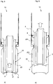
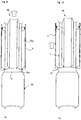
- Fig. 1 to 10 show an exemplary embodiment of a filling device 10 according to the invention in different phases during a method according to the invention for filling a can body as a container 20. Since the figures show a sequence of the filling device in different process steps, not all reference numerals are given in each figure. However, due to the equivalence of the representations, the assignment to the unmarked components and objects is readily given.
- Fig. 1 shows a filling device 10, which according to the invention without pollluft effetslos return air duct and measuring medium free, and has a simple construction with a minimum number of valves.
- the container to be filled 20 which is here a can body, whose substantially cylindrical shape is slightly tapered at the upper end to the coaxial filling opening 21 out.
- the taper serves primarily for receiving the cover, not shown here, which is placed after completion of filling and connected by crimping with the edge of the can.
- the inventive method uses this difference between the container inner diameter d l and the diameter d Do of the container opening 21, which may for example be between 70 and 99.5%, at doses usually between 80 to 90% of the container inner diameter d l .
- a filling device according to the invention can also be provided for containers whose container opening diameter is significantly smaller than the container inner diameter, as is the case for example with bottles, provided that they are precisely manufactured with exactly determinable diameter and volume.
- the filling device 10 shown has a movable filling valve 1, which consists of a filling tube 2 and controllably guided piston 3.
- the filling valve 1 opens by the piston 3 is moved with respect to the filling tube 2 upwards.
- the filling valve 1 has an outer diameter d Fa , which is adapted to the diameter d Do of the container opening 21 so that the filling valve 1 can be introduced without contact and friction through the container opening 21 in the container 20.
- the method provides that the container 20 (as in Fig. 1 is arranged so with respect to the filling valve 1 that a coaxial centric insertion of the filling valve 1 through the container opening 21 into the container 20 is possible - this can be achieved by axially moving the filling valve 1 or the container 20, for example via a corresponding movable Container receptacle (not shown) take place.
- the container 20 with the container volume V B is filled with ambient air (but possibly also with another gas, eg inert gas or carbon dioxide) at an outlet pressure po (eg ambient pressure, or optionally - if filling takes place in a closed system - preset outlet pressure).
- ambient air but possibly also with another gas, eg inert gas or carbon dioxide
- an outlet pressure po eg ambient pressure, or optionally - if filling takes place in a closed system - preset outlet pressure.
- a predetermined for insertion into the container 20 portion of the filling valve 1 marked, which has the volume V F, which is to the present invention are in the range of 49 to 99% of the container volume V B and in the example shown about 65% of the container volume V B accounts.
- the volume V F of the portion of the filling valve 1 of a container-filler combination predetermined for introduction into the container 20 is known and predetermined.
- the filling device 10 shows an attachment tube 4 which is arranged coaxially around the filling valve 1 and is movable relative thereto and controlled independently thereof.
- the Follventil 1 is sealingly slidably mounted in the tower tube 4 by means of a sliding seal 6.
- the sliding seal 6 is circumferentially in front of a collar 5, which surrounds the filling tube 2 at a predetermined distance from the filling valve opening of the filling valve 1, at which the filling valve 1 opens.
- This predetermined distance of the collar 5 to the filling valve opening of the filling valve 1 depends on the length of the intended for insertion portion of the filling valve 1 and thus from the height H of the container 20; because it is provided according to the invention that the collar 5 comes to rest (or at a defined distance to) the annular shoulder 7 when the intended for insertion section of the filling valve 1 is completely received in the container 20, ie in principle up to Container bottom 22 extends as in FIG Fig. 4 you can see.
- the attachment tube 4 For sealing placement on the container opening 21, the attachment tube 4 has an annular shoulder 7 at the end, which is formed with a sealing seat 8 adapted to the container opening 21.
- a sealing seat 8 adapted to the container opening 21.
- the annular shoulder 7 of the top tube 4 whose inner diameter is adapted here to the inner diameter d l of the container 20, projects radially inwardly to the container opening 21, whose diameter d Do is smaller than this inner diameter d l , can be placed.
- the annular shoulder 7 is dimensioned such that an annular gap remains around the filling valve 1 in order to permit fluid communication, ie gas exchange with the container interior.
- step a) of the inventive method for filling a cylindrical container 20 with a fluid is, as in Fig. 2 indicated by the block arrow, the filling valve 1 introduced into the container 20 up to a predetermined height h 1 , without the attachment tube 2 is moved.
- gas present there with known outlet pressure p 0 , eg ambient pressure
- the height h 1 is predetermined for each tank-filling valve combination for which the volumes V B and V F are respectively known, in dependence on the backpressure provided for the respective filling operation, which is selected with respect to a designated filling pressure, as follows is explained.
- the in Fig. 3 is shown, while the filling valve 1 is maintained at the first predetermined height h 1 , the attachment tube 4 is moved relative to the filling valve 1, which is indicated by the block arrow, and placed on the container opening 21, wherein the sealing seat 8 gas-tight sealing at the the container opening 21 rests limiting container edge. It is now, divided into the partial volume V A1 in the top tube 4 to the filling valve 1 and in the subvolume V B1 in the container 20 to the filling valve 1, a defined amount of gas within the container 20 and the tower tube 4 at the known outlet pressure p 0 before.
- the filling device 10 is formed with the sealing seat 8 on the top tube 4 so that a fluid communication or gas exchange with the container interior is allowed, ie, that the partial volumes V A1 and V B1 in the top tube 4 and in the container 20 to the Filling valve 1 are connected to each other via the annular gap, which is present in the region of the container opening 21 and the sealing seat 8-bearing annular shoulder 7 to the filling valve 1.
- Fig. 4 shows step c), in which the filling valve 1, as indicated by the block arrow, with the predetermined portion is completely inserted into the container 20, while the top tube 4 remains in the sealing position at the container opening 21.
- Complete insertion can, as in the example shown, mean that the filling valve opening of the filling valve 1 comes into contact with the bottom 22 of the container 20.
- the filling valve opening of the filling valve 1 can be shaped corresponding to the shaped bottom 22 of the container 20.
- it can also be provided, for example, to reliably avoid damage to the bottom 22, that even with a fully inserted filling valve 1, a certain, defined distance to the bottom 22 remains.
- the back pressure p G is thus not adjusted by supplying a clamping gas, but is determined (based on the initial pressure p 0 present ) by the height h 1 , to which the filling valve 1 is introduced in step a) in the container 20, before in Step b) the container 20 is sealed with the top tube 4.
- the remaining parameters influencing the adjustable back pressure are the known and fixed dimensions or volumes of the container and the filling device.
- the predetermined height h 1 , to which the filling valve 1 is inserted, is not on the in Fig. 2 and 3 shown insertion depth limited, but is determined by the counterpressure to be achieved p G.
- the height h 1 is preferably between the container opening 21 and the container bottom 22, but it is also heights h 1 ⁇ H includes, ie, that the filling valve 1 in step a) can also be positioned at height H of the container opening 21 or above, if in step b) the sealing takes place by placing the attachment tube 4.
- the back pressure p G which is then achieved in step c) by the completely introduced filling valve 1, is greater, the greater the predetermined height h 1 .
- the filling valve 1 already in step a) are completely introduced (the predetermined height h 1 is the height of the container bottom 22), so that after sealing with the top tube 4 in step b) no pressure increase by further introduction of the filling valve takes place and the actual filling process in steps d) and e) thus takes place at initial pressure p 0 .
- h 1 it may also be advantageous for h 1 to be "too low" in order to set the back pressure p G intentionally below the saturation pressure of the liquid.
- h 1 may also be advantageous for h 1 to be "too low" in order to set the back pressure p G intentionally below the saturation pressure of the liquid.
- an intended initial foaming of the liquid can be produced. This foam on the annular Surface of the fluid in the annular gap 23 creates a desired in this case separation of the fluid and the air, resulting in a reduced oxygen uptake.
- FIGS. 5 and 6 show the filling process with the steps d) and e):
- the filling valve 1 opens (block arrow in Fig. 5 ), so that the fluid with a predetermined filling pressure p F flows into the annular gap 23, while at the same time the opened filling valve 1 is moved upward (block arrow in FIG Fig. 6 ).
- Filling pressure p F and back pressure p G are chosen so that when pressure is equalized between the filling pressure p F and the back pressure p G of the fluid level S within the annular gap 23 at a defined distance above the filling valve opening of the filling valve 1.
- the speed of the upward movement of the filling valve 1 is matched with the inflow velocity of the fluid, so that the fluid level S is always above the Guventilö réelle of the valve 1 with the valve opening in the annular gap 23 and the lower layer filling is achieved, which is very fast feasible.
- a gas partial volume .DELTA.V is released to the filling valve 1 1 within the top tube 4, which corresponds to the inflow into the container 20 fluid volume such that the sum of the gas partial volume .DELTA.V 1 in top tube 4 and a gas partial volume .DELTA.V 2 in the container above the Fluid level S corresponds to the difference volume .DELTA.V. Since thus this gas volume .DELTA.V remains constant, and the predetermined back pressure p G remains constant, whereby the filling device 10 according to the invention without any measuring means to control the filling process.
- step f The only controlled upward movement of the filling valve 1 is determined for a given container-filler combination depending on the respectively provided filling pressure, so that, as in Fig. 7 it can be seen, in step f), the relative upward movement of the open filling valve 1 is terminated upon reaching a second predetermined height h 2 , which is present in the region of the container opening 21.
- the height h 2 is selected so that the volume of fluid then present in the container 20 corresponds to the predetermined filling volume.
- h 2 is when the predetermined height is reached reaches the predetermined filling volume in the container 20, without corrections must be made, since due to the existing pressure equalization when stopping the filling valve 1 no further Inflow of fluid takes place even if the valve 1 is still open, before, as in Flg. 8 is closed.
- step g the closed filling valve 1 is removed from the container 20, on the opening 21 of the top tube 4 is still arranged sealingly.
- the partial volumes V B2 and V A2 available for the gas quantity present in the system are increased so that the back pressure p G is reduced to a predetermined relief pressure p E which can correspond to the outlet pressure p 0. before in step h) ( Fig. 10 ) and the top tube 4 is removed from the container opening 21, and thus output pressure po prevails, and thus the filling process for the respective container 20 is completed.
- a next container 20 can then be supplied to be filled in the same way.
- the filling valve 1 has a flow guide 9, which the outflowing fluid in a defined vortex or vortex movement offset. This avoids that the leaking fluid with filling pressure radially collides with the container wall and back spills, which increasingly gas bubbles are included, which would accumulate to the end of the filling process and then lead to a strong foaming.
- the flow guiding structure can, as Fig. 11 shows, on an inner side of the filling tube 2 or, as in the examples of Fig. 12 to 14 on an outer side of the piston 3 above the respective sealing surfaces 2 ', 3' are present. Contrary to what is shown, cooperating flow guide structures may also be present on both the fill tube and the piston, just as the fill valve may be an outwardly opening fill valve.
- FIGS. 11 and 12 each show in the filling tube 2 and on the piston 3, a Strömungsleit Quilt 9, which is formed by a spiral web similar to a thread. It can also be provided a plurality of parallel spiral webs.
- FIGS. 13 and 14 show a blading as Strömungsleit Scheme on the outside of the piston 3. Other than shown, a blading may also be present on the inside of the filling tube.
- the flow-guiding blading 9 on the piston 3 in Fig. 13 is formed by a ring vanes, which are curved at least in two planes to put the flowing fluid in a vortex or vortex movement.
- Fig . 14 shows an example in which the flow-guiding blading 9 is formed by a ring of blades, which are unbent here.
- the piston 3 is rotatably drivable, as indicated by the block arrow.
- the piston 3 is rotatably supported, as the fluid flowing past the blades causes the piston 3 to rotate, thus promoting the swirling even without drive.
- the filling device has the advantage that the contact of the fluid with atmospheric oxygen is also reduced without previous evacuation or gas purging.
- the contact surface of the fluid in the annular gap around the filling valve in the container is merely a circular ring having a ring width which is the difference of half the inner diameter of the container d i and half the outer diameter of the filling valve d Fs .
- the fluid level in the annular gap is always above the end face or filling valve opening of the filling valve, the fluid only comes into contact with the gas present in the container at the annular contact surface.
- the annulus is an extremely small contact surface, which makes the absorption of gas (especially atmospheric oxygen) into the fluid very low.
- the filling quantity is determined by the known geometries (volume) of the container (can) and the filling valve, which at the same time constitutes a displacement element, and of the attachment tube.
- volume volume
- the filling valve various designs are conceivable.
- expensive measuring devices such as MID sensors, as they are used in the prior art omitted.
- actuator and appropriate control logic is set, can be dispensed with. A fill level correction is not required.
- the size of the annular surface between the container wall and filling valve is dependent on the container diameter and container opening diameter and therefore can also be very small - takes place the contact surface reduction, which has a reduced gas absorption in the bottled fluid result.
- the surrounding air present in the container is flushed by carbon dioxide, which causes a very high carbon dioxide consumption, the amount of oxygen is already significantly reduced by the mechanical displacement of the air from the container due to the geometric conditions.
- the lower-layer filling process around the filling valve in particular in the embodiment with the flow-guiding structure, less or no swirling of filled fluid and residual gas in the container occurs, as a result of which oxygen uptake is further minimized.
- the back pressure required for pressure filling which is generated in the prior art by compressed gas, usually carbon dioxide or nitrogen, mechanically provided by the sealing of the filling opening during insertion of the filling valve, so that clamping gas and corresponding means for supplying can be omitted.
- the desired pressure is simply adjustable by determining the required insertion depth given geometric conditions.
- a return air-tube-free pressure filling is made possible, whereby the separate control, cleaning and maintenance of the return air pipes or return air lines is eliminated, which is still required in the prior art:
- the container to be filled and a reservoir on the filling device (ring bowl) form a chamber during the actual filling process.
- the liquid flowing into the container to be filled displaces the gas present there into the storage container.
- the known multi-chamber solutions have not been enforced so far, since the individual chambers can only be properly separated if a Gregut lymph is accepted. A real separation of the chambers is only complex in terms of apparatus.
- both measuring means for monitoring the filling quantity and rinsing or tensioning gas can be dispensed with be, with the filling device used is very simple design and hardly prone to error. But even if the invention preferably makes do without rinsing and clamping gas, the implementation of such steps in the inventive method is not excluded.
Landscapes
- Engineering & Computer Science (AREA)
- Mechanical Engineering (AREA)
- Filling Of Jars Or Cans And Processes For Cleaning And Sealing Jars (AREA)
- Filling Or Discharging Of Gas Storage Vessels (AREA)
Applications Claiming Priority (1)
| Application Number | Priority Date | Filing Date | Title |
|---|---|---|---|
| EP17000013.7A EP3345862B1 (fr) | 2017-01-05 | 2017-01-05 | Système de remplissage et procédé de remplissage de récipients cylindriques |
Publications (4)
| Publication Number | Publication Date |
|---|---|
| EP3345863A2 true EP3345863A2 (fr) | 2018-07-11 |
| EP3345863A3 EP3345863A3 (fr) | 2019-06-12 |
| EP3345863C0 EP3345863C0 (fr) | 2023-06-21 |
| EP3345863B1 EP3345863B1 (fr) | 2023-06-21 |
Family
ID=57758472
Family Applications (3)
| Application Number | Title | Priority Date | Filing Date |
|---|---|---|---|
| EP17000013.7A Active EP3345862B1 (fr) | 2017-01-05 | 2017-01-05 | Système de remplissage et procédé de remplissage de récipients cylindriques |
| EP17842415.6A Withdrawn EP3565780A1 (fr) | 2017-01-05 | 2017-12-20 | Procédé de remplissage de récipients conservés cylindriques, en particulier de boîtes et système de remplissage constitué d'un dispositif de remplissage et d'un récipient |
| EP17002044.0A Active EP3345863B1 (fr) | 2017-01-05 | 2017-12-20 | Système de remplissage et procédé de remplissage de canettes |
Family Applications Before (2)
| Application Number | Title | Priority Date | Filing Date |
|---|---|---|---|
| EP17000013.7A Active EP3345862B1 (fr) | 2017-01-05 | 2017-01-05 | Système de remplissage et procédé de remplissage de récipients cylindriques |
| EP17842415.6A Withdrawn EP3565780A1 (fr) | 2017-01-05 | 2017-12-20 | Procédé de remplissage de récipients conservés cylindriques, en particulier de boîtes et système de remplissage constitué d'un dispositif de remplissage et d'un récipient |
Country Status (7)
| Country | Link |
|---|---|
| US (1) | US10894704B2 (fr) |
| EP (3) | EP3345862B1 (fr) |
| CN (1) | CN110167869B (fr) |
| ES (1) | ES2786560T3 (fr) |
| HU (1) | HUE049288T2 (fr) |
| PL (1) | PL3345862T3 (fr) |
| WO (1) | WO2018127268A1 (fr) |
Families Citing this family (2)
| Publication number | Priority date | Publication date | Assignee | Title |
|---|---|---|---|---|
| EP4019143A1 (fr) * | 2020-12-22 | 2022-06-29 | Orient Express Int'l Ltd | Procédé de remplissage d'un récipient à l'aide une pompe de distribution et cartouche, système de gestion et machine correspondants |
| US12263570B2 (en) | 2022-06-06 | 2025-04-01 | Enerpac Tool Group Corp. | Hydraulic tools |
Citations (1)
| Publication number | Priority date | Publication date | Assignee | Title |
|---|---|---|---|---|
| DE102008030948A1 (de) | 2008-07-02 | 2010-01-21 | Khs Ag | Füllsystem zum Füllen von Flaschen oder dergleichen Behältern sowie Füllmaschine |
Family Cites Families (32)
| Publication number | Priority date | Publication date | Assignee | Title |
|---|---|---|---|---|
| GB285257A (en) * | 1927-02-28 | 1928-02-16 | Robert Powley And Sons Ltd | Improvements in and relating to apparatus for filling bottles with liquids |
| DE1186768B (de) | 1963-08-13 | 1965-02-04 | Jagenberg Werke Ag | Verfahren und Vorrichtung zum Abfuellen von Fluessigkeiten |
| BE770848A (fr) * | 1970-08-29 | 1971-12-16 | Holstein & Kappert Maschine Fa | Procede et dispositif pour le soutirage d'un liquide dans un recipient |
| US3830265A (en) * | 1972-08-14 | 1974-08-20 | American Can Co | Method and apparatus for filling a container |
| US3951186A (en) * | 1974-05-17 | 1976-04-20 | Fmc Corporation | Gas flushing system for beverage filler |
| US3949791A (en) | 1975-03-31 | 1976-04-13 | Fmc Corporation | Piston type liquid filler valve |
| US4079762A (en) * | 1976-09-24 | 1978-03-21 | Par-Way Mfg. Co. | Spirally discharging nozzle and poppet valve for non-splash discharge of liquids into cans or the like |
| US4121633A (en) * | 1976-10-18 | 1978-10-24 | Jerry Diez | Transfer device for heat sensitive material |
| DE3102678A1 (de) * | 1981-01-28 | 1982-09-02 | Holstein Und Kappert Gmbh, 4600 Dortmund | Verfahren zum abfuellen von sauerstoffempfindlichen fluessigkeiten |
| US4750533A (en) * | 1981-11-27 | 1988-06-14 | Crown Cork & Seal Company, Inc. | Filling valve for counterpressure filling of cans |
| US4986318A (en) * | 1981-11-27 | 1991-01-22 | Crown Cork & Seal Company, Inc. | Filling valve for counterpressure filling of cans |
| SE431186B (sv) * | 1982-08-17 | 1984-01-23 | Tetra Pak Int | Fyllare vid forpackningsmaskiner |
| DE3444515A1 (de) * | 1984-12-06 | 1986-06-19 | Hans Dipl.-Chem. 8953 Obergünzburg Gabler | Verfahren zum fuellen von steifen behaeltnissen |
| US5145008A (en) * | 1985-04-05 | 1992-09-08 | Crown Cork & Seal Company, Inc. | Filling valve for counterpressure filling of cans |
| US4915146A (en) * | 1988-03-14 | 1990-04-10 | John R. Nalbach Engineering Co., Inc. | Measuring flask for use in a filling machine |
| JPH0431293A (ja) * | 1990-05-15 | 1992-02-03 | Mitsubishi Heavy Ind Ltd | 高速液体充填装置 |
| ZA915594B (en) * | 1990-08-13 | 1993-03-31 | Colgate Palmolive Co | Package filling method and apparatus |
| DE9416912U1 (de) * | 1994-10-20 | 1995-11-16 | Krones Ag Hermann Kronseder Maschinenfabrik, 93073 Neutraubling | Füllorgan für Gefäßfüllmaschinen |
| IT1293960B1 (it) * | 1997-06-20 | 1999-03-11 | Mbf Spa | Macchina riempitrice rotativa per il riempimento di contenitori con liquidi |
| SE9801399D0 (sv) | 1998-04-21 | 1998-04-21 | Astra Pharma Prod | Method and apparatus for filling containers |
| EP2112120B1 (fr) * | 2005-07-28 | 2012-02-22 | Sidel Participations | Soupape de remplissage équipée d'un capteur de défaillance |
| DE102006051237B4 (de) * | 2006-10-31 | 2015-09-10 | Khs Gmbh | Spülgaseinbringung in Getränkedosen |
| DE102010022875A1 (de) * | 2010-06-07 | 2011-12-08 | Khs Gmbh | Füllelement sowie Füllmaschine zum Füllen von Flaschen oder dergleichen Behältern |
| DE102011100560B3 (de) | 2011-05-05 | 2012-03-15 | Leibinger Smb Technik Gmbh | Vorrichtung zum Befüllen eines Behältnisses mit einer zum Verzehr bestimmten Flüssigkeit |
| DE102011103876B3 (de) * | 2011-06-10 | 2012-03-15 | Leibinger Smb Technik Gmbh | Vorrichtung zum Befüllen eines Behältnisses mit einer insbesondere zum Verzehr bestimmten Flüssigkeit |
| EP3008009A1 (fr) * | 2013-06-11 | 2016-04-20 | Leibinger GmbH | Capuchon soupape pour le remplissage et le vidage de contenants |
| DE102013113070B3 (de) | 2013-11-26 | 2015-03-19 | Khs Gmbh | Füllelement sowie Füllmaschine |
| DE102014102953A1 (de) * | 2014-03-06 | 2015-09-10 | Krones Ag | Vorrichtung und Verfahren zum Befüllen eines Behälters mit einem Füllprodukt |
| DE102014106404A1 (de) * | 2014-05-07 | 2015-11-12 | Khs Gmbh | Füllvorrichtung |
| CN204022440U (zh) | 2014-08-28 | 2014-12-17 | 宁波德永机械有限公司 | 一种易拉罐灌装阀 |
| DE102014014317B4 (de) * | 2014-10-01 | 2018-06-07 | Leibinger Gmbh | Vorrichtung und Verfahren zum messmittellosen Befüllen eines Behältnisses |
| DE202014104841U1 (de) * | 2014-10-10 | 2014-10-27 | Krones Ag | Vorrichtung zum Befüllen eines Behälters mit einem Füllprodukt |
-
2017
- 2017-01-05 ES ES17000013T patent/ES2786560T3/es active Active
- 2017-01-05 EP EP17000013.7A patent/EP3345862B1/fr active Active
- 2017-01-05 HU HUE17000013A patent/HUE049288T2/hu unknown
- 2017-01-05 PL PL17000013T patent/PL3345862T3/pl unknown
- 2017-12-20 US US16/468,065 patent/US10894704B2/en active Active
- 2017-12-20 CN CN201780082572.0A patent/CN110167869B/zh active Active
- 2017-12-20 EP EP17842415.6A patent/EP3565780A1/fr not_active Withdrawn
- 2017-12-20 WO PCT/EP2017/001433 patent/WO2018127268A1/fr not_active Ceased
- 2017-12-20 EP EP17002044.0A patent/EP3345863B1/fr active Active
Patent Citations (1)
| Publication number | Priority date | Publication date | Assignee | Title |
|---|---|---|---|---|
| DE102008030948A1 (de) | 2008-07-02 | 2010-01-21 | Khs Ag | Füllsystem zum Füllen von Flaschen oder dergleichen Behältern sowie Füllmaschine |
Also Published As
| Publication number | Publication date |
|---|---|
| WO2018127268A1 (fr) | 2018-07-12 |
| US20200017343A1 (en) | 2020-01-16 |
| CN110167869A (zh) | 2019-08-23 |
| US10894704B2 (en) | 2021-01-19 |
| EP3345862B1 (fr) | 2020-03-04 |
| EP3345863C0 (fr) | 2023-06-21 |
| EP3345862A1 (fr) | 2018-07-11 |
| EP3345863A3 (fr) | 2019-06-12 |
| EP3565780A1 (fr) | 2019-11-13 |
| HUE049288T2 (hu) | 2020-09-28 |
| EP3345863B1 (fr) | 2023-06-21 |
| ES2786560T3 (es) | 2020-10-13 |
| PL3345862T3 (pl) | 2020-08-24 |
| CN110167869B (zh) | 2021-09-03 |
Similar Documents
| Publication | Publication Date | Title |
|---|---|---|
| EP2417051B1 (fr) | Système de remplissage | |
| EP2010447B1 (fr) | Élément de remplissage et machine de remplissage avec élément de remplissage | |
| EP2788275B1 (fr) | Élément de remplissage pourvu d'un tube trinox | |
| EP0953542B1 (fr) | Vanne de remplissage pour une machine de remplissage | |
| EP2307306B1 (fr) | Système de remplissage pour remplir des bouteilles ou récipients similaires et machine de remplissage correspondante | |
| EP2576421B1 (fr) | Elément de remplissage et machine de remplissage servant à remplir des bouteilles ou récipients analogues | |
| DE3928009A1 (de) | Vorrichtung zum fuellen von behaeltern | |
| DE19836500A1 (de) | Füllsystem | |
| EP3802400B1 (fr) | Système de remplissage de récipients avec un produit de remplissage liquide et machine de remplissage | |
| DE2340613A1 (de) | Verfahren und einrichtung zum fuellen von behaeltern mit einer gas enthaltenden fluessigkeit | |
| DE102009009340A1 (de) | Verfahren zum Druckfüllen von Flaschen oder dergleichen Behältern sowie Füllsystem und Füllmaschine zum Durchführen des Verfahrens | |
| DE102015118612A1 (de) | Vorrichtung zum Befüllen von Behältern mit einem Füllprodukt | |
| DE102005003222A1 (de) | Vorrichtung zum Füllen von Gefäßen | |
| EP3345863B1 (fr) | Système de remplissage et procédé de remplissage de canettes | |
| DE3325338A1 (de) | Fuelleinrichtung fuer stillgetraenke | |
| WO2017153255A1 (fr) | Élément de remplissage muni d'un orifice de sortie de gaz de purge de forme annulaire | |
| EP3008009A1 (fr) | Capuchon soupape pour le remplissage et le vidage de contenants | |
| WO2011154067A1 (fr) | Élément de remplissage et machine de remplissage pour le remplissage de bouteilles ou de récipients analogues | |
| DE102016105552A1 (de) | Füllventil zum Befüllen eines Behälters mit einem Füllprodukt | |
| AT509070B1 (de) | Vorrichtung und verfahren zum abfüllen von flüssigkeiten | |
| DE2123865A1 (de) | Füllelement | |
| DE2638749C3 (de) | Vorrichtung zum Füllen von Flaschen bei gleichbleibendem Druck | |
| DE69100519T2 (de) | Füllvorrichtung. | |
| DE4323746A1 (de) | Verfahren und Vorrichtung zur Beeinflussung der Füllmenge beim Abfüllen von Flüssigkeiten in Flaschen | |
| DE2848604C2 (de) | Vorrichtung zum Abfüllen von Getränken |
Legal Events
| Date | Code | Title | Description |
|---|---|---|---|
| PUAI | Public reference made under article 153(3) epc to a published international application that has entered the european phase |
Free format text: ORIGINAL CODE: 0009012 |
|
| STAA | Information on the status of an ep patent application or granted ep patent |
Free format text: STATUS: THE APPLICATION HAS BEEN PUBLISHED |
|
| AK | Designated contracting states |
Kind code of ref document: A2 Designated state(s): AL AT BE BG CH CY CZ DE DK EE ES FI FR GB GR HR HU IE IS IT LI LT LU LV MC MK MT NL NO PL PT RO RS SE SI SK SM TR |
|
| AX | Request for extension of the european patent |
Extension state: BA ME |
|
| PUAL | Search report despatched |
Free format text: ORIGINAL CODE: 0009013 |
|
| AK | Designated contracting states |
Kind code of ref document: A3 Designated state(s): AL AT BE BG CH CY CZ DE DK EE ES FI FR GB GR HR HU IE IS IT LI LT LU LV MC MK MT NL NO PL PT RO RS SE SI SK SM TR |
|
| AX | Request for extension of the european patent |
Extension state: BA ME |
|
| RIC1 | Information provided on ipc code assigned before grant |
Ipc: B67C 3/26 20060101AFI20190507BHEP |
|
| STAA | Information on the status of an ep patent application or granted ep patent |
Free format text: STATUS: REQUEST FOR EXAMINATION WAS MADE |
|
| 17P | Request for examination filed |
Effective date: 20191210 |
|
| RBV | Designated contracting states (corrected) |
Designated state(s): AL AT BE BG CH CY CZ DE DK EE ES FI FR GB GR HR HU IE IS IT LI LT LU LV MC MK MT NL NO PL PT RO RS SE SI SK SM TR |
|
| STAA | Information on the status of an ep patent application or granted ep patent |
Free format text: STATUS: EXAMINATION IS IN PROGRESS |
|
| 17Q | First examination report despatched |
Effective date: 20211123 |
|
| GRAP | Despatch of communication of intention to grant a patent |
Free format text: ORIGINAL CODE: EPIDOSNIGR1 |
|
| STAA | Information on the status of an ep patent application or granted ep patent |
Free format text: STATUS: GRANT OF PATENT IS INTENDED |
|
| INTG | Intention to grant announced |
Effective date: 20230105 |
|
| GRAS | Grant fee paid |
Free format text: ORIGINAL CODE: EPIDOSNIGR3 |
|
| GRAA | (expected) grant |
Free format text: ORIGINAL CODE: 0009210 |
|
| STAA | Information on the status of an ep patent application or granted ep patent |
Free format text: STATUS: THE PATENT HAS BEEN GRANTED |
|
| AK | Designated contracting states |
Kind code of ref document: B1 Designated state(s): AL AT BE BG CH CY CZ DE DK EE ES FI FR GB GR HR HU IE IS IT LI LT LU LV MC MK MT NL NO PL PT RO RS SE SI SK SM TR |
|
| REG | Reference to a national code |
Ref country code: CH Ref legal event code: EP |
|
| REG | Reference to a national code |
Ref country code: DE Ref legal event code: R096 Ref document number: 502017014933 Country of ref document: DE |
|
| REG | Reference to a national code |
Ref country code: AT Ref legal event code: REF Ref document number: 1580802 Country of ref document: AT Kind code of ref document: T Effective date: 20230715 |
|
| REG | Reference to a national code |
Ref country code: IE Ref legal event code: FG4D Free format text: LANGUAGE OF EP DOCUMENT: GERMAN |
|
| U01 | Request for unitary effect filed |
Effective date: 20230721 |
|
| U07 | Unitary effect registered |
Designated state(s): AT BE BG DE DK EE FI FR IT LT LU LV MT NL PT SE SI Effective date: 20230727 |
|
| REG | Reference to a national code |
Ref country code: LT Ref legal event code: MG9D |
|
| PG25 | Lapsed in a contracting state [announced via postgrant information from national office to epo] |
Ref country code: NO Free format text: LAPSE BECAUSE OF FAILURE TO SUBMIT A TRANSLATION OF THE DESCRIPTION OR TO PAY THE FEE WITHIN THE PRESCRIBED TIME-LIMIT Effective date: 20230921 |
|
| PG25 | Lapsed in a contracting state [announced via postgrant information from national office to epo] |
Ref country code: RS Free format text: LAPSE BECAUSE OF FAILURE TO SUBMIT A TRANSLATION OF THE DESCRIPTION OR TO PAY THE FEE WITHIN THE PRESCRIBED TIME-LIMIT Effective date: 20230621 Ref country code: HR Free format text: LAPSE BECAUSE OF FAILURE TO SUBMIT A TRANSLATION OF THE DESCRIPTION OR TO PAY THE FEE WITHIN THE PRESCRIBED TIME-LIMIT Effective date: 20230621 Ref country code: GR Free format text: LAPSE BECAUSE OF FAILURE TO SUBMIT A TRANSLATION OF THE DESCRIPTION OR TO PAY THE FEE WITHIN THE PRESCRIBED TIME-LIMIT Effective date: 20230922 |
|
| PG25 | Lapsed in a contracting state [announced via postgrant information from national office to epo] |
Ref country code: SK Free format text: LAPSE BECAUSE OF FAILURE TO SUBMIT A TRANSLATION OF THE DESCRIPTION OR TO PAY THE FEE WITHIN THE PRESCRIBED TIME-LIMIT Effective date: 20230621 |
|
| PG25 | Lapsed in a contracting state [announced via postgrant information from national office to epo] |
Ref country code: ES Free format text: LAPSE BECAUSE OF FAILURE TO SUBMIT A TRANSLATION OF THE DESCRIPTION OR TO PAY THE FEE WITHIN THE PRESCRIBED TIME-LIMIT Effective date: 20230621 |
|
| PG25 | Lapsed in a contracting state [announced via postgrant information from national office to epo] |
Ref country code: IS Free format text: LAPSE BECAUSE OF FAILURE TO SUBMIT A TRANSLATION OF THE DESCRIPTION OR TO PAY THE FEE WITHIN THE PRESCRIBED TIME-LIMIT Effective date: 20231021 |
|
| PG25 | Lapsed in a contracting state [announced via postgrant information from national office to epo] |
Ref country code: SM Free format text: LAPSE BECAUSE OF FAILURE TO SUBMIT A TRANSLATION OF THE DESCRIPTION OR TO PAY THE FEE WITHIN THE PRESCRIBED TIME-LIMIT Effective date: 20230621 Ref country code: SK Free format text: LAPSE BECAUSE OF FAILURE TO SUBMIT A TRANSLATION OF THE DESCRIPTION OR TO PAY THE FEE WITHIN THE PRESCRIBED TIME-LIMIT Effective date: 20230621 Ref country code: RO Free format text: LAPSE BECAUSE OF FAILURE TO SUBMIT A TRANSLATION OF THE DESCRIPTION OR TO PAY THE FEE WITHIN THE PRESCRIBED TIME-LIMIT Effective date: 20230621 Ref country code: IS Free format text: LAPSE BECAUSE OF FAILURE TO SUBMIT A TRANSLATION OF THE DESCRIPTION OR TO PAY THE FEE WITHIN THE PRESCRIBED TIME-LIMIT Effective date: 20231021 Ref country code: ES Free format text: LAPSE BECAUSE OF FAILURE TO SUBMIT A TRANSLATION OF THE DESCRIPTION OR TO PAY THE FEE WITHIN THE PRESCRIBED TIME-LIMIT Effective date: 20230621 Ref country code: CZ Free format text: LAPSE BECAUSE OF FAILURE TO SUBMIT A TRANSLATION OF THE DESCRIPTION OR TO PAY THE FEE WITHIN THE PRESCRIBED TIME-LIMIT Effective date: 20230621 |
|
| U20 | Renewal fee for the european patent with unitary effect paid |
Year of fee payment: 7 Effective date: 20231228 |
|
| PG25 | Lapsed in a contracting state [announced via postgrant information from national office to epo] |
Ref country code: PL Free format text: LAPSE BECAUSE OF FAILURE TO SUBMIT A TRANSLATION OF THE DESCRIPTION OR TO PAY THE FEE WITHIN THE PRESCRIBED TIME-LIMIT Effective date: 20230621 |
|
| REG | Reference to a national code |
Ref country code: DE Ref legal event code: R097 Ref document number: 502017014933 Country of ref document: DE |
|
| PLBE | No opposition filed within time limit |
Free format text: ORIGINAL CODE: 0009261 |
|
| STAA | Information on the status of an ep patent application or granted ep patent |
Free format text: STATUS: NO OPPOSITION FILED WITHIN TIME LIMIT |
|
| 26N | No opposition filed |
Effective date: 20240322 |
|
| PG25 | Lapsed in a contracting state [announced via postgrant information from national office to epo] |
Ref country code: MC Free format text: LAPSE BECAUSE OF FAILURE TO SUBMIT A TRANSLATION OF THE DESCRIPTION OR TO PAY THE FEE WITHIN THE PRESCRIBED TIME-LIMIT Effective date: 20230621 |
|
| GBPC | Gb: european patent ceased through non-payment of renewal fee |
Effective date: 20231220 |
|
| PG25 | Lapsed in a contracting state [announced via postgrant information from national office to epo] |
Ref country code: MC Free format text: LAPSE BECAUSE OF FAILURE TO SUBMIT A TRANSLATION OF THE DESCRIPTION OR TO PAY THE FEE WITHIN THE PRESCRIBED TIME-LIMIT Effective date: 20230621 |
|
| REG | Reference to a national code |
Ref country code: IE Ref legal event code: MM4A |
|
| PG25 | Lapsed in a contracting state [announced via postgrant information from national office to epo] |
Ref country code: IE Free format text: LAPSE BECAUSE OF NON-PAYMENT OF DUE FEES Effective date: 20231220 |
|
| PG25 | Lapsed in a contracting state [announced via postgrant information from national office to epo] |
Ref country code: GB Free format text: LAPSE BECAUSE OF NON-PAYMENT OF DUE FEES Effective date: 20231220 |
|
| PG25 | Lapsed in a contracting state [announced via postgrant information from national office to epo] |
Ref country code: IE Free format text: LAPSE BECAUSE OF NON-PAYMENT OF DUE FEES Effective date: 20231220 Ref country code: GB Free format text: LAPSE BECAUSE OF NON-PAYMENT OF DUE FEES Effective date: 20231220 |
|
| U20 | Renewal fee for the european patent with unitary effect paid |
Year of fee payment: 8 Effective date: 20241218 |
|
| PGFP | Annual fee paid to national office [announced via postgrant information from national office to epo] |
Ref country code: CH Payment date: 20250101 Year of fee payment: 8 |
|
| PG25 | Lapsed in a contracting state [announced via postgrant information from national office to epo] |
Ref country code: CY Free format text: LAPSE BECAUSE OF FAILURE TO SUBMIT A TRANSLATION OF THE DESCRIPTION OR TO PAY THE FEE WITHIN THE PRESCRIBED TIME-LIMIT; INVALID AB INITIO Effective date: 20171220 |
|
| PG25 | Lapsed in a contracting state [announced via postgrant information from national office to epo] |
Ref country code: HU Free format text: LAPSE BECAUSE OF FAILURE TO SUBMIT A TRANSLATION OF THE DESCRIPTION OR TO PAY THE FEE WITHIN THE PRESCRIBED TIME-LIMIT; INVALID AB INITIO Effective date: 20171220 |
|
| PG25 | Lapsed in a contracting state [announced via postgrant information from national office to epo] |
Ref country code: TR Free format text: LAPSE BECAUSE OF FAILURE TO SUBMIT A TRANSLATION OF THE DESCRIPTION OR TO PAY THE FEE WITHIN THE PRESCRIBED TIME-LIMIT Effective date: 20230621 |
|
| U20 | Renewal fee for the european patent with unitary effect paid |
Year of fee payment: 9 Effective date: 20251216 |
|
| U1O | Appointed representative for the unitary patent procedure deleted after the registration of the unitary effect | ||
| REG | Reference to a national code |
Ref country code: CH Ref legal event code: H13 Free format text: ST27 STATUS EVENT CODE: U-0-0-H10-H13 (AS PROVIDED BY THE NATIONAL OFFICE) Effective date: 20260723 |