EP3346027A1 - Pompe à hydrogène électrochimique - Google Patents
Pompe à hydrogène électrochimique Download PDFInfo
- Publication number
- EP3346027A1 EP3346027A1 EP17206862.9A EP17206862A EP3346027A1 EP 3346027 A1 EP3346027 A1 EP 3346027A1 EP 17206862 A EP17206862 A EP 17206862A EP 3346027 A1 EP3346027 A1 EP 3346027A1
- Authority
- EP
- European Patent Office
- Prior art keywords
- metal sheet
- vents
- metal
- gas diffusion
- anode
- Prior art date
- Legal status (The legal status is an assumption and is not a legal conclusion. Google has not performed a legal analysis and makes no representation as to the accuracy of the status listed.)
- Withdrawn
Links
- UFHFLCQGNIYNRP-UHFFFAOYSA-N Hydrogen Chemical compound [H][H] UFHFLCQGNIYNRP-UHFFFAOYSA-N 0.000 title claims abstract description 157
- 239000001257 hydrogen Substances 0.000 title claims abstract description 152
- 229910052739 hydrogen Inorganic materials 0.000 title claims abstract description 152
- 229910052751 metal Inorganic materials 0.000 claims abstract description 444
- 239000002184 metal Substances 0.000 claims abstract description 444
- 239000007789 gas Substances 0.000 claims abstract description 263
- 238000009792 diffusion process Methods 0.000 claims abstract description 149
- 239000003054 catalyst Substances 0.000 claims abstract description 115
- 239000012528 membrane Substances 0.000 claims abstract description 96
- 239000003792 electrolyte Substances 0.000 claims abstract description 91
- 238000009826 distribution Methods 0.000 claims description 21
- 229910000831 Steel Inorganic materials 0.000 claims description 11
- 239000000843 powder Substances 0.000 claims description 11
- 239000010959 steel Substances 0.000 claims description 11
- 239000000835 fiber Substances 0.000 claims description 4
- 238000004891 communication Methods 0.000 description 69
- 239000000463 material Substances 0.000 description 17
- 239000000446 fuel Substances 0.000 description 11
- 238000000034 method Methods 0.000 description 11
- BASFCYQUMIYNBI-UHFFFAOYSA-N platinum Chemical compound [Pt] BASFCYQUMIYNBI-UHFFFAOYSA-N 0.000 description 10
- OKTJSMMVPCPJKN-UHFFFAOYSA-N Carbon Chemical compound [C] OKTJSMMVPCPJKN-UHFFFAOYSA-N 0.000 description 8
- 238000006243 chemical reaction Methods 0.000 description 8
- 230000003247 decreasing effect Effects 0.000 description 8
- 230000008901 benefit Effects 0.000 description 6
- 239000000470 constituent Substances 0.000 description 6
- 239000012530 fluid Substances 0.000 description 6
- 230000006870 function Effects 0.000 description 6
- RTAQQCXQSZGOHL-UHFFFAOYSA-N Titanium Chemical compound [Ti] RTAQQCXQSZGOHL-UHFFFAOYSA-N 0.000 description 5
- 229910052799 carbon Inorganic materials 0.000 description 5
- 230000006835 compression Effects 0.000 description 5
- 238000007906 compression Methods 0.000 description 5
- -1 for example Substances 0.000 description 5
- 230000000149 penetrating effect Effects 0.000 description 5
- 229910052697 platinum Inorganic materials 0.000 description 5
- 229910001220 stainless steel Inorganic materials 0.000 description 5
- 239000010935 stainless steel Substances 0.000 description 5
- CURLTUGMZLYLDI-UHFFFAOYSA-N Carbon dioxide Chemical compound O=C=O CURLTUGMZLYLDI-UHFFFAOYSA-N 0.000 description 4
- 230000003746 surface roughness Effects 0.000 description 4
- 239000010936 titanium Substances 0.000 description 4
- XLYOFNOQVPJJNP-UHFFFAOYSA-N water Substances O XLYOFNOQVPJJNP-UHFFFAOYSA-N 0.000 description 4
- MWUXSHHQAYIFBG-UHFFFAOYSA-N Nitric oxide Chemical compound O=[N] MWUXSHHQAYIFBG-UHFFFAOYSA-N 0.000 description 3
- 229910002092 carbon dioxide Inorganic materials 0.000 description 3
- 230000005611 electricity Effects 0.000 description 3
- 238000003487 electrochemical reaction Methods 0.000 description 3
- 229910002804 graphite Inorganic materials 0.000 description 3
- 239000010439 graphite Substances 0.000 description 3
- 239000012535 impurity Substances 0.000 description 3
- 239000011159 matrix material Substances 0.000 description 3
- 238000002156 mixing Methods 0.000 description 3
- 230000035699 permeability Effects 0.000 description 3
- 238000012545 processing Methods 0.000 description 3
- 238000003860 storage Methods 0.000 description 3
- 229910052719 titanium Inorganic materials 0.000 description 3
- 230000015572 biosynthetic process Effects 0.000 description 2
- 230000000694 effects Effects 0.000 description 2
- 239000011357 graphitized carbon fiber Substances 0.000 description 2
- 239000007791 liquid phase Substances 0.000 description 2
- 239000011295 pitch Substances 0.000 description 2
- 238000000746 purification Methods 0.000 description 2
- 238000005096 rolling process Methods 0.000 description 2
- 239000011800 void material Substances 0.000 description 2
- 238000010792 warming Methods 0.000 description 2
- QNRATNLHPGXHMA-XZHTYLCXSA-N (r)-(6-ethoxyquinolin-4-yl)-[(2s,4s,5r)-5-ethyl-1-azabicyclo[2.2.2]octan-2-yl]methanol;hydrochloride Chemical compound Cl.C([C@H]([C@H](C1)CC)C2)CN1[C@@H]2[C@H](O)C1=CC=NC2=CC=C(OCC)C=C21 QNRATNLHPGXHMA-XZHTYLCXSA-N 0.000 description 1
- 229920003934 Aciplex® Polymers 0.000 description 1
- 229920000049 Carbon (fiber) Polymers 0.000 description 1
- 229910001200 Ferrotitanium Inorganic materials 0.000 description 1
- YCKRFDGAMUMZLT-UHFFFAOYSA-N Fluorine atom Chemical compound [F] YCKRFDGAMUMZLT-UHFFFAOYSA-N 0.000 description 1
- 229920000557 Nafion® Polymers 0.000 description 1
- 229910052782 aluminium Inorganic materials 0.000 description 1
- XAGFODPZIPBFFR-UHFFFAOYSA-N aluminium Chemical compound [Al] XAGFODPZIPBFFR-UHFFFAOYSA-N 0.000 description 1
- QVGXLLKOCUKJST-UHFFFAOYSA-N atomic oxygen Chemical compound [O] QVGXLLKOCUKJST-UHFFFAOYSA-N 0.000 description 1
- 238000005219 brazing Methods 0.000 description 1
- 239000006229 carbon black Substances 0.000 description 1
- 239000001569 carbon dioxide Substances 0.000 description 1
- 239000004917 carbon fiber Substances 0.000 description 1
- 238000005266 casting Methods 0.000 description 1
- 239000000084 colloidal system Substances 0.000 description 1
- 238000001816 cooling Methods 0.000 description 1
- 239000013078 crystal Substances 0.000 description 1
- 238000011161 development Methods 0.000 description 1
- 238000005868 electrolysis reaction Methods 0.000 description 1
- 230000007613 environmental effect Effects 0.000 description 1
- 239000010419 fine particle Substances 0.000 description 1
- 229910052731 fluorine Inorganic materials 0.000 description 1
- 239000011737 fluorine Substances 0.000 description 1
- 239000002803 fossil fuel Substances 0.000 description 1
- 238000010438 heat treatment Methods 0.000 description 1
- 150000002431 hydrogen Chemical class 0.000 description 1
- 238000010030 laminating Methods 0.000 description 1
- 239000007788 liquid Substances 0.000 description 1
- 238000004519 manufacturing process Methods 0.000 description 1
- 238000005058 metal casting Methods 0.000 description 1
- 150000002739 metals Chemical class 0.000 description 1
- 239000003607 modifier Substances 0.000 description 1
- 239000007800 oxidant agent Substances 0.000 description 1
- 239000001301 oxygen Substances 0.000 description 1
- 229910052760 oxygen Inorganic materials 0.000 description 1
- 239000003208 petroleum Substances 0.000 description 1
- 238000007747 plating Methods 0.000 description 1
- 239000011148 porous material Substances 0.000 description 1
- 238000010248 power generation Methods 0.000 description 1
- 238000006722 reduction reaction Methods 0.000 description 1
- 238000011160 research Methods 0.000 description 1
- 230000000630 rising effect Effects 0.000 description 1
- 238000005245 sintering Methods 0.000 description 1
- 238000004381 surface treatment Methods 0.000 description 1
- 238000009423 ventilation Methods 0.000 description 1
- 238000003466 welding Methods 0.000 description 1
Images



Classifications
-
- C—CHEMISTRY; METALLURGY
- C25—ELECTROLYTIC OR ELECTROPHORETIC PROCESSES; APPARATUS THEREFOR
- C25B—ELECTROLYTIC OR ELECTROPHORETIC PROCESSES FOR THE PRODUCTION OF COMPOUNDS OR NON-METALS; APPARATUS THEREFOR
- C25B15/00—Operating or servicing cells
- C25B15/08—Supplying or removing reactants or electrolytes; Regeneration of electrolytes
-
- B—PERFORMING OPERATIONS; TRANSPORTING
- B01—PHYSICAL OR CHEMICAL PROCESSES OR APPARATUS IN GENERAL
- B01D—SEPARATION
- B01D53/00—Separation of gases or vapours; Recovering vapours of volatile solvents from gases; Chemical or biological purification of waste gases, e.g. engine exhaust gases, smoke, fumes, flue gases, aerosols
- B01D53/22—Separation of gases or vapours; Recovering vapours of volatile solvents from gases; Chemical or biological purification of waste gases, e.g. engine exhaust gases, smoke, fumes, flue gases, aerosols by diffusion
- B01D53/228—Separation of gases or vapours; Recovering vapours of volatile solvents from gases; Chemical or biological purification of waste gases, e.g. engine exhaust gases, smoke, fumes, flue gases, aerosols by diffusion characterised by specific membranes
-
- B—PERFORMING OPERATIONS; TRANSPORTING
- B01—PHYSICAL OR CHEMICAL PROCESSES OR APPARATUS IN GENERAL
- B01D—SEPARATION
- B01D53/00—Separation of gases or vapours; Recovering vapours of volatile solvents from gases; Chemical or biological purification of waste gases, e.g. engine exhaust gases, smoke, fumes, flue gases, aerosols
- B01D53/32—Separation of gases or vapours; Recovering vapours of volatile solvents from gases; Chemical or biological purification of waste gases, e.g. engine exhaust gases, smoke, fumes, flue gases, aerosols by electrical effects other than those provided for in group B01D61/00
- B01D53/326—Separation of gases or vapours; Recovering vapours of volatile solvents from gases; Chemical or biological purification of waste gases, e.g. engine exhaust gases, smoke, fumes, flue gases, aerosols by electrical effects other than those provided for in group B01D61/00 in electrochemical cells
-
- C—CHEMISTRY; METALLURGY
- C25—ELECTROLYTIC OR ELECTROPHORETIC PROCESSES; APPARATUS THEREFOR
- C25B—ELECTROLYTIC OR ELECTROPHORETIC PROCESSES FOR THE PRODUCTION OF COMPOUNDS OR NON-METALS; APPARATUS THEREFOR
- C25B1/00—Electrolytic production of inorganic compounds or non-metals
- C25B1/01—Products
- C25B1/02—Hydrogen or oxygen
-
- C—CHEMISTRY; METALLURGY
- C25—ELECTROLYTIC OR ELECTROPHORETIC PROCESSES; APPARATUS THEREFOR
- C25B—ELECTROLYTIC OR ELECTROPHORETIC PROCESSES FOR THE PRODUCTION OF COMPOUNDS OR NON-METALS; APPARATUS THEREFOR
- C25B11/00—Electrodes; Manufacture thereof not otherwise provided for
- C25B11/02—Electrodes; Manufacture thereof not otherwise provided for characterised by shape or form
- C25B11/03—Electrodes; Manufacture thereof not otherwise provided for characterised by shape or form perforated or foraminous
- C25B11/031—Porous electrodes
-
- C—CHEMISTRY; METALLURGY
- C25—ELECTROLYTIC OR ELECTROPHORETIC PROCESSES; APPARATUS THEREFOR
- C25B—ELECTROLYTIC OR ELECTROPHORETIC PROCESSES FOR THE PRODUCTION OF COMPOUNDS OR NON-METALS; APPARATUS THEREFOR
- C25B9/00—Cells or assemblies of cells; Constructional parts of cells; Assemblies of constructional parts, e.g. electrode-diaphragm assemblies; Process-related cell features
- C25B9/17—Cells comprising dimensionally-stable non-movable electrodes; Assemblies of constructional parts thereof
- C25B9/19—Cells comprising dimensionally-stable non-movable electrodes; Assemblies of constructional parts thereof with diaphragms
-
- F—MECHANICAL ENGINEERING; LIGHTING; HEATING; WEAPONS; BLASTING
- F04—POSITIVE - DISPLACEMENT MACHINES FOR LIQUIDS; PUMPS FOR LIQUIDS OR ELASTIC FLUIDS
- F04B—POSITIVE-DISPLACEMENT MACHINES FOR LIQUIDS; PUMPS
- F04B45/00—Pumps or pumping installations having flexible working members and specially adapted for elastic fluids
- F04B45/04—Pumps or pumping installations having flexible working members and specially adapted for elastic fluids having plate-like flexible members, e.g. diaphragms
- F04B45/047—Pumps having electric drive
-
- B—PERFORMING OPERATIONS; TRANSPORTING
- B01—PHYSICAL OR CHEMICAL PROCESSES OR APPARATUS IN GENERAL
- B01D—SEPARATION
- B01D2256/00—Main component in the product gas stream after treatment
- B01D2256/16—Hydrogen
-
- H—ELECTRICITY
- H01—ELECTRIC ELEMENTS
- H01M—PROCESSES OR MEANS, e.g. BATTERIES, FOR THE DIRECT CONVERSION OF CHEMICAL ENERGY INTO ELECTRICAL ENERGY
- H01M8/00—Fuel cells; Manufacture thereof
- H01M8/06—Combination of fuel cells with means for production of reactants or for treatment of residues
- H01M8/0662—Treatment of gaseous reactants or gaseous residues, e.g. cleaning
- H01M8/0681—Reactant purification by the use of electrochemical cells
-
- Y—GENERAL TAGGING OF NEW TECHNOLOGICAL DEVELOPMENTS; GENERAL TAGGING OF CROSS-SECTIONAL TECHNOLOGIES SPANNING OVER SEVERAL SECTIONS OF THE IPC; TECHNICAL SUBJECTS COVERED BY FORMER USPC CROSS-REFERENCE ART COLLECTIONS [XRACs] AND DIGESTS
- Y02—TECHNOLOGIES OR APPLICATIONS FOR MITIGATION OR ADAPTATION AGAINST CLIMATE CHANGE
- Y02E—REDUCTION OF GREENHOUSE GAS [GHG] EMISSIONS, RELATED TO ENERGY GENERATION, TRANSMISSION OR DISTRIBUTION
- Y02E60/00—Enabling technologies; Technologies with a potential or indirect contribution to GHG emissions mitigation
- Y02E60/30—Hydrogen technology
- Y02E60/50—Fuel cells
Definitions
- the present disclosure relates to an electrochemical hydrogen pump.
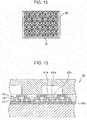
- Japanese Patent No. 4733380 has disclosed that as shown in Fig. 12 , a support member 30 for an electrolyte membrane of a high differential pressure electrochemical cell is used as a gas diffusion layer which is in contact with the electrolyte membrane. That is, in one surface of the support member 30, rectangular recess portions is formed, and in the other surface, rhombic recess portions is formed. In addition, an overlapping portion of the two types of recess portions forms a through-hole 31 through which a fluid passes.
- clogging of a fluid flow path which may occur in a related mesh type gas diffusion layer can be suppressed, and in addition, a rigidity can be secured which can withstand the difference in pressure between a high pressure side and a low pressure side of the electrochemical cell. Accordingly, since being supported by the support member 30, the electrolyte membrane can be suppressed from being deformed to a point of rupture.
- Japanese Unexamined Patent Application Publication No. 2000-58073 has disclosed that as shown in Fig. 13 , a laminate in which porous layers 41, 42, and 43 are laminated to each other is used as a gas diffusion layer of a fuel cell.
- the porous layers 41, 42, and 43 have opening portions 41 a, 42a, and 43a, respectively.
- those opening portions 41a, 42a, and 43a have different opening diameters from each other, and the opening diameters are gradually decreased from a collector 38 to a catalyst layer 36a. Accordingly, an output and an energy efficiency of the fuel cell can be improved.
- one non-limiting and exemplary embodiment provides an electrochemical hydrogen pump which is able to reduce a probability in which an electrolyte membrane is ruptured when pressed to an anode gas diffusion layer by the difference in pressure between a cathode and an anode.
- the techniques disclosed here feature an electrochemical hydrogen pump comprising: an electrolyte membrane having a pair of primary surfaces; a cathode catalyst layer provided on one primary surface of the electrolyte membrane; an anode catalyst layer provided on the other primary surface of the electrolyte membrane; a cathode gas diffusion layer provided on the cathode catalyst layer; an anode gas diffusion layer provided on the anode catalyst layer; and a voltage application device applying a voltage between the cathode catalyst layer and the anode catalyst layer.
- the anode gas diffusion layer includes a laminate formed of metal sheets which are provided with vents, and among the metal sheets, the maximum diameter of vents provided in a first metal sheet adjacent to the anode catalyst layer is smaller than the maximum diameter of vents provided in a second metal sheet adjacent to the first metal sheet.
- the electrochemical hydrogen pump according to one aspect of the present disclosure has an effect capable of reducing the probability in which the electrolyte membrane pressed to the anode gas diffusion layer by the difference in pressure between the anode and the cathode is ruptured as compared to that in the past.
- an electrochemical hydrogen pump of a first aspect of the present disclosure includes an electrolyte membrane having a pair of primary surfaces; a cathode catalyst layer provided on one primary surface of the electrolyte membrane; an anode catalyst layer provided on the other primary surface of the electrolyte membrane; a cathode gas diffusion layer provided on the cathode catalyst layer; an anode gas diffusion layer provided on the anode catalyst layer; and a voltage application device applying a voltage between the cathode catalyst layer and the anode catalyst layer.
- the anode gas diffusion layer includes a laminate formed of metal sheets which are provided with vents, and among the metal sheets, the maximum diameter of vents provided in a first metal sheet adjacent to the anode catalyst layer is smaller than the maximum diameter of vents provided in a second metal sheet adjacent to the first metal sheet.
- an electrochemical hydrogen pump of a second aspect of the present disclosure includes an electrolyte membrane having a pair of primary surfaces; a cathode catalyst layer provided on one primary surface of the electrolyte membrane; an anode catalyst layer provided on the other primary surface of the electrolyte membrane; a cathode gas diffusion layer provided on the cathode catalyst layer; an anode gas diffusion layer provided on the anode catalyst layer; and a voltage application device applying a voltage between the cathode catalyst layer and the anode catalyst layer.
- the anode gas diffusion layer includes a laminate formed of metal sheets which are provided with vents, and among the metal sheets, the average diameter of vents provided in a first metal sheet adjacent to the anode catalyst layer is smaller than the average diameter of vents provided in a second metal sheet adjacent to the first metal sheet.
- a probability in which the electrolyte membrane pressed to the anode gas diffusion layer by the difference in pressure between the anode and the cathode can be reduced as compared to that in the past.
- the maximum diameter of the vents of the first metal sheet is smaller than the maximum diameter of the vents of the second metal sheet, compared to the case in which the relationship between the first and the second metal sheets is opposite to that described above, the sag of the electrolyte membrane into the vent of the first metal sheet can be suppressed.
- the average diameter of the vents of the first metal sheet is smaller than the average diameter of the vents of the second metal sheet, compared to the case in which the relationship between the first and the second metal sheets is opposite to that described above, the sag of the electrolyte membrane into the vent of the first metal sheet can be suppressed.
- the anode gas diffusion layer only includes the laminate formed of metal sheets which are provided with vents, and among the metal sheets, the maximum diameter of the vents provided in the first metal sheet adjacent to the anode catalyst layer may be smaller than the maximum diameter of the vents provided in the second metal sheet adjacent to the first metal sheet.
- the anode gas diffusion layer is the laminate formed of metal sheets, a compression strain amount by the press can be reduced.
- a material having a high elasticity as compared to that of the anode gas diffusion layer can be selected for the cathode gas diffusion layer, so that the followability to the deformation of the electrolyte membrane is improved. That is, an increase in contact resistance between the cathode gas diffusion layer and the cathode catalyst layer can be suppressed.
- the maximum diameter of the vents of the first metal sheet is smaller than the maximum diameter of the vents of the second metal sheet, the probability in which the electrolyte membrane is ruptured can be reduced as compared to that in the past.
- the anode gas diffusion layer only includes the laminate formed of metal sheets which are provided with vents, and among the metal sheets, the average diameter of the vents provided in the first metal sheet adjacent to the anode catalyst layer may be smaller than the average diameter of the vents provided in the second metal sheet adjacent to the first metal sheet.
- the anode gas diffusion layer is the laminate formed of metal sheets, a compression strain amount by the press can be reduced.
- a material having a high elasticity as compared to that of the anode gas diffusion layer may be selected for the cathode gas diffusion layer, so that the followability to the deformation of the electrolyte membrane is improved. That is, an increase in contact resistance between the cathode gas diffusion layer and the cathode catalyst layer can be suppressed.
- the maximum diameter of the vents of the first metal sheet is smaller than the maximum diameter of the vents of the second metal sheet, the probability in which the electrolyte membrane is ruptured can be reduced as compared to that in the past.
- the number of the vents per unit surface area of a primary surface of the first metal sheet may be larger than the number of the vents per unit surface area of a primary surface of the second metal sheet.
- an open area of the vents of the first metal sheet may be equivalent to or more than an open area of the vents of the second metal sheet.
- the gas diffusivity of the first metal sheet can be improved.
- the first metal sheet may have a hardness lower than that of the second metal sheet.
- the processability of the vent of the metal sheet becomes difficult.
- the hardness of the first metal sheet is set lower than the hardness of the second metal sheet, fine processing of the vents of the first metal sheet can be easily performed.
- the hardness of the second metal sheet is set higher than the hardness of the first metal sheet, the rigidity of the second metal sheet can be increased.
- one of a pair of primary surfaces of the second metal sheet which is adjacent to the first metal sheet has a roughness higher than the roughness of one of a pair of primary surfaces of the first metal sheet which is adjacent to the anode catalyst layer.
- one of a pair of primary surfaces of the first metal sheet which is adjacent to the second metal sheet has a roughness higher than the roughness of one of a pair of primary surfaces of the first metal sheet which is adjacent to the anode catalyst layer.
- the surface roughness conforms to JIS B0601:2001.
- At least one of the primary surface of the first metal sheet adjacent to the second metal sheet and the primary surface of the second metal sheet adjacent to the first metal sheet is formed to have appropriate irregularities, so that an anode gas is allowed to diffuse between those primary surfaces. Accordingly, compared to the case in which the irregularities as described above are not formed, the gas diffusivity of the first metal sheet is improved.
- At least one metal sheet among the metal sheets may have a communication path communicating between through-holes.
- the electrochemical hydrogen pump of this aspect can allow an anode gas to uniformly diffuse as compared to that in the past. That is, since the metal sheet of the laminate of the anode gas diffusion layer has a communication path, an anode gas passing through the anode gas diffusion layer from an appropriate flow path member can be supplied not only in one direction but also in an arbitrary direction. Hence, when metal sheets having different arrangement patterns of the communication paths are laminated to each other, the direction of an anode gas flow in the anode gas diffusion layer can be arbitrarily determined. Accordingly, the gas diffusivity of the anode gas diffusion layer is improved.
- the anode gas when the structure is formed so that the anode gas is supplied into the through-holes of the laminate of the anode gas diffusion layer through a gas flow path of an appropriate flow path member, if this laminate has not the communication path described above, the anode gas is not allowed to flow into a through-hole of the laminate of the anode gas diffusion layer located above a vertical line to a portion at which no gas flow path of the flow path member is provided, and the gas diffusion in the anode gas diffusion layer may be non-uniformed in some cases.
- the anode gas in the anode gas diffusion layer of the electrochemical hydrogen pump of this aspect, through the communication path described above, the anode gas can be allowed to flow into the through-hole of the laminate of the anode gas diffusion layer as described above, and hence the gas diffusion in the anode gas diffusion layer can be suppressed from being non-uniformed.
- the communication path described above may communicate between through-holes provided in the same metal sheet adjacent to the metal sheet in which the communication path is provided.
- the communication path described above may communicate between through-holes of different metal sheets each adjacent to the metal sheet in which the communication path is provided.
- the laminate of the anode gas diffusion layer includes the communication path described above, an anode gas passing through the laminate can be supplied not only in a direction penetrating the laminate but also in a direction parallel to a primary surface of the laminate. Hence, the gas diffusivity of the anode gas diffusion layer is improved.
- the laminate of the anode gas diffusion layer may include a metal sheet formed of a metal sintered body through which a gas is allowed to diffuse.
- the laminate of the anode gas diffusion layer includes a metal sheet formed of a metal sintered body, compared to the case in which without using a metal sheet formed of a metal sintered body, the laminate is formed of metal steel sheets which are provided with vents, gas permeability and gas diffusivity required for the anode gas diffusion layer can be easily secured.
- the first metal sheet may be formed of a metal sintered body
- the second metal sheet may be a laminate formed of metal steel sheets which are provided with vents.
- the metal sintered body has a surface roughness higher than the surface roughness of the metal steel sheet, an area at which the first metal sheet is in contact with the anode catalyst layer can be further increased, and the diffusivity of the anode gas can be improved.
- the cathode gas diffusion layer may include a third metal sheet which is provided with vents, and the distribution of average diameters of the vents of the third metal sheet may be wider than the distribution of average diameters of the vents of the first metal sheet.
- the first metal sheet may be formed of a metal powder sintered body
- the third metal sheet may be formed of a metal fiber sintered body
- the first metal sheet may be formed of a metal mesh
- the second metal sheet may be a laminate formed of metal steel sheets which are provided with vents.
- vents is provided in a metal steel sheet
- the size of the vent can be easily decreased, and the porosity thereof can also be easily increased.
- the probability in which a pressed electrolyte membrane is ruptured is not only reduced, but also the area at which the first metal sheet is in contact with the anode catalyst layer can be increase, so that the gas diffusivity can also be improved.
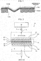
- Fig. 2 is a view showing one example of an electrochemical hydrogen pump of a first embodiment.
- An electrochemical hydrogen pump 16 includes a membrane electrode assembly 15 (hereinafter, referred to as the "MEA 15"), a first plate 1A, a second plate 1C, and a voltage application device 13.
- the MEA 15 includes an electrolyte membrane 4, a cathode catalyst layer 3C, an anode catalyst layer 3A, a cathode gas diffusion layer 2C, and an anode gas diffusion layer 2A, and those layers are bonded to each other in a laminated state.
- the electrolyte membrane 4 has a pair of primary surfaces.
- the electrolyte membrane 4 is a proton conductive high molecular weight membrane capable of permeating a proton (H + ).
- any membrane may be used.
- the electrolyte membrane 4 a fluorine-based high molecular weight electrolyte membrane may be mentioned.
- the electrolyte membrane 4 for example, Nafion (registered trade name, manufactured by Dupont) or Aciplex (trade name, manufactured by Asahi Kasei Corp.) may be used.
- the cathode catalyst layer 3C is provided on one primary surface of the electrolyte membrane 4.
- the cathode catalyst layer 3C contains, for example, platinum as a catalyst metal, the catalyst metal is not limited thereto.
- the anode catalyst layer 3A is provided on the other primary surface of the electrolyte membrane 4.
- the anode catalyst layer 3A contains, for example, RulrFeOx as a catalyst metal, the catalyst metal is not limited thereto.
- a method for preparing a catalyst for the cathode catalyst layer 3C and the anode catalyst layer 3A various methods may be mentioned, and hence the method is not particularly limited.
- a carrier of the catalyst for example, an electrically conductive porous material powder or a carbon-based powder may be mentioned.
- the carbon-based powder for example, a powder of graphite, carbon black, active carbon having an electrical conductivity, or the like may be mentioned.
- a method for supporting platinum or another catalyst metal on a carrier, such as carbon is not particularly limited.
- a method, such as powder mixing or liquid phase mixing, may be used.
- a method in which a carrier, such as carbon, is dispersed in a catalyst component colloid liquid so that a catalyst component is adsorbed on the carrier may be mentioned.
- a carrier such as carbon
- platinum or another catalyst metal may be supported thereon by a method similar to that described above.
- a supporting state of platinum or another catalyst metal on a carrier is not particularly limited.
- a catalyst metal may be formed into fine particles and then supported on a carrier in a highly dispersed state.
- the cathode gas diffusion layer 2C is provided on the cathode catalyst layer 3C.
- a paper-like layer may be used which is formed of highly elastic graphitized carbon fibers or a porous body prepared by performing platinum plating on the surface of a titanium powder sintered body.
- the former graphitized carbon fibers for example, by a heat treatment performed at 2,000°C or more, graphite crystals are grown, and carbon fibers are changed into graphite fibers.
- the anode gas diffusion layer 2A is provided on the anode catalyst layer 3A.
- the anode gas diffusion layer 2A is required to have a rigidity so as to withstand the press of the electrolyte membrane 4 by the difference in pressure between the cathode and the anode of the electrochemical hydrogen pump 16.
- any structure may be used. A particular structure of the anode gas diffusion layer 2A will be described later.
- the first plate 1A (separator plate) is provided with a gas flow path 14A through which an anode gas flows. That is, the first plate 1A is a member to supply the anode gas to the anode gas diffusion layer 2A.
- a serpentine-shaped gas flow path 14A communicating with a manifold not shown in the figure is formed, and a formation region of this gas flow path 14A is arranged so as to be in contact with a primary surface of the anode gas diffusion layer 2A.
- the anode gas contains at least a hydrogen gas and water molecules (moisture).
- the anode gas for example, a reformed gas containing hydrogen or a hydrogen-containing gas produced by a water electrolysis method may be mentioned.
- the second plate 1C (separator plate) is provided with a gas flow path 14C through which a cathode gas flows. That is, through the gas flow path 14C of the second plate 1C, the cathode gas from the cathode gas diffusion layer 2C flows.
- a serpentine-shaped gas flow path 14C communicating with a manifold not shown in the figure is formed, and a formation region of this gas flow path 14C is arranged so as to be in contact with a primary surface of the cathode gas diffusion layer 2C.
- the cathode gas for example, a highly pure hydrogen gas may be mentioned.
- the MEA 15 is sandwiched at the bottom and the top surfaces thereof by the first plate 1A and the second plate 1C, respectively, so that a single cell of the electrochemical hydrogen pump 16 is formed.
- the voltage application device 13 applies a voltage between the cathode catalyst layer 3C and the anode catalyst layer 3A.
- a high potential terminal of the voltage application device 13 is connected to the electrically conductive first plate 1A
- a low potential terminal of the voltage application device 13 is connected to the electrically conductive second plate 1C.
- any structure may be used.
- the voltage application device 13 may be able to adjust an application voltage.
- the voltage application device 13 when being connected to a direct current power source, such as a battery, a solar cell, or a fuel cell, the voltage application device 13 includes a DC/DC converter, and when being connected to an alternating current power source, such as a commercial power source, the voltage application device 13 includes an AC/DC converter.
- a direct current power source such as a battery, a solar cell, or a fuel cell
- the voltage application device 13 when being connected to a direct current power source, such as a battery, a solar cell, or a fuel cell, the voltage application device 13 includes a DC/DC converter, and when being connected to an alternating current power source, such as a commercial power source, the voltage application device 13 includes an AC/DC converter.
- the cathode gas diffusion layer 2C and the anode gas diffusion layer 2A are electricity feeding bodies of the cathode and the anode, respectively, of the MEA 15. That is, the cathode gas diffusion layer 2C functions to feed electricity between the second plate 1C and the cathode catalyst layer 3C, and the anode gas diffusion layer 2A functions to feed electricity between the first plate 1A and the anode catalyst layer 3A.
- the cathode gas diffusion layer 2C also functions to allow a gas to diffuse between the gas flow path 14C of the second plate 1C and the cathode catalyst layer 3C
- the anode gas diffusion layer 2A also function to allow a gas to diffuse between the gas flow path 14A of the first plate 1A and the anode catalyst layer 3A.
- the anode gas flowing through the gas flow path 14A of the first plate 1 A diffuses to the surface of the anode catalyst layer 3A through the anode gas diffusion layer 2A.
- a cooling device is provided for the single cell of the electrochemical hydrogen pump 16, and by laminating at least two cells, a stack structure may be formed from single cells.
- the electrochemical hydrogen pump 16 includes an anode chamber 8 and a cathode chamber 7.
- the inside of the anode chamber 8 communicates with an anode inlet pipe 11 and also communicates with the gas flow path 14A of the first plate 1A through a fluid flow path not shown (such as a pipe or a manifold). Accordingly, the anode gas flowing into the anode chamber 8 through the anode inlet pipe 11 is supplied to the gas flow path 14A of the first plate 1A.
- a fluid flow path not shown such as a pipe or a manifold
- the inside of the cathode chamber 7 communicates with a cathode outlet pipe 12 and also communicates with the gas flow path 14C of the second plate 1C through a fluid flow path not shown (such as a pipe or a manifold). Accordingly, after flowing into the cathode chamber 7 through the gas flow path 14C of the second plate 1C, the cathode gas (hydrogen gas) passing through the MEA 15 is then supplied to the cathode outlet pipe 12.
- an on-off valve 9 (such as an electromagnetic valve) is provided for the cathode outlet pipe 12, and since the on-off valve 9 is appropriately opened or closed, the cathode gas is stored in a high pressure hydrogen tank 10. Accordingly, the cathode gas as described above is used, for example, as a fuel of a hydrogen-using apparatus (such as a fuel cell) not shown.
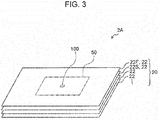
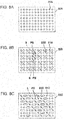
- Figs. 3 , 4A, 4B, 4C, and 5 are views each showing one example of the anode gas diffusion layer of the electrochemical hydrogen pump of the first embodiment.
- Fig. 4A is a plan view of a first metal sheet 22F in a region 100 which is a part of a gas diffusion portion 50 of the anode gas diffusion layer 2A.
- Fig. 4B is a plan view of a second metal sheet 22S in this region 100.
- Fig. 4C is a plan view of the first metal sheet 22F laminated on the second metal sheet 22S.
- Fig. 5 shows a cross-sectional view taken along the line V-V of Fig. 4C together with the electrolyte membrane 4.
- the anode gas diffusion layer 2A includes a laminate 20 of metal sheets 22 which are provided with vents (not shown in Fig. 3 ).
- the metal sheets 22 separated from each other are shown, the metal sheets 22 are actually laminated to each other.
- the metal sheets may be integrally bonded to each other, for example, by welding, adhesion, or brazing.
- primary surfaces of the metal sheets 22 in a laminated state may be surface-bonded to each other by diffusion bonding or the like.
- the metal sheet 22 is formed so that an area other than the vents has no gas permeability.
- the metal sheet 22 may be a metal steel sheet having a thickness of approximately several tens to several hundreds of micrometers (such as approximately 100 ⁇ m), the metal sheet 22 is not limited thereto.
- This metal sheet 22 may be manufactured, for example, by casting or rolling of a metal. Since a metal casting method and a metal rolling method have been known, particular description thereof will be omitted.
- vents 25F may be formed in a matrix form (lattice shape) in a longitudinal and a lateral direction at regular intervals.
- the vent 25F may have an arbitrary shape.
- the vent 25F may be, for example, as shown in Fig. 4A , a round hole having a diameter of approximately several tens of micrometers, or although not shown in the figure, the vent 25F may be an oval-shaped hole having a minor axis of approximately several tens of micrometers.
- a material of the first metal sheet 22F will be described in examples.
- vents 25S may be formed in a matrix form (lattice shape) in a longitudinal and a lateral direction at regular intervals.
- the vent 25S may have an arbitrary shape.
- the vent 25S may be, for example, as shown in Fig. 4B , a round hole having a diameter of approximately several tens of micrometers, or although not shown in the figure, the vent 25S may have an oval-shaped hole having a minor axis of approximately several tens of micrometers.
- a material of the second metal sheet 22S will be described in examples.
- the maximum diameter of the vents 25F provided in the first metal sheet 22F adjacent to the anode catalyst layer 3A is smaller than the maximum diameter of the vents 25S provided in the second metal sheet 22S adjacent to the first metal sheet 22F.
- the "maximum diameter of the vents" indicates the maximum value among the diameters of the round holes.
- the "maximum diameter of the vents" indicates the maximum value among the major axes of the oval-shaped holes.
- the reason for this is that when the electrolyte membrane 4 is pressed above an oval-shaped hole, the sag amount of the electrolyte membrane 4 is dominantly determined by the major axis length of the oval-shaped hole.
- the average diameter of the vents 25F provided in the first metal sheet 22F adjacent to the anode catalyst layer 3A is smaller than the average diameter of the vents 25S provided in the second metal sheet 22S adjacent to the first metal sheet 22F.
- the "average diameter of the vents" indicates the value obtained by dividing the total of the diameters of the round holes by the number of the round holes.
- the "average diameter of the vents" indicates the value obtained by dividing the total of the major axis lengths of the oval-shaped holes by the number of the oval-shaped holes. The reason for this is that when the electrolyte membrane 4 is pressed above an oval-shaped hole, the sag amount of the electrolyte membrane 4 is dominantly determined by the major axis length of the oval-shaped hole.
- the number of the vents 25F per unit area of a primary surface of the first metal sheet 22F is larger than the number of the vents 25S per unit area of a primary surface of the second metal sheet 22S.
- an open area of the vents 25F of the first metal sheet 22F is equivalent to or more than an open area of the vents 25S of the second metal sheet 22S.
- the "open area of the vents 25F of the first metal sheet 22F" and the “open area of the vents 25S of the second metal sheet 22S” represent the total open area of all the vents 25F and the total open area of all the vents 25S, respectively.
- the vents 25F of the first metal sheet 22F and the vents 25S of the second metal sheet 22S are arranged so that the openings of the vents 25S are overlapped with some openings of the vents 25F.
- the portions at which the vents 25F of the first metal sheet 22F are overlapped with the vents 25S of the second metal sheet 22S are each formed as a ventilation space between the first metal sheet 22F and the second metal sheet 22S in a plan view.
- vents 25F of the first metal sheet 22F and the vents 25S of the second metal sheet 22S are shown by way of example and are not limited to those described in this example.
- the controller includes, for example, a computing circuit and a storage circuit storing a control program.
- a computing circuit for example, an MPU and/or a CPU may be mentioned.
- a storage circuit for example, a memory may be mentioned.
- the controller may be formed of a single controller performing a centralized control or may be formed of controllers performing a decentralized control in cooperation with each other.
- protons pass through the electrolyte membrane 4 together with water molecules and are brought into contact with the cathode.
- a reduction reaction is performed by the protons passing through the electrolyte membrane 4 and electrons from the cathode gas diffusion layer 2C, so that the cathode gas (hydrogen gas) is generated (Formula (2)).
- anode gas containing impurities can be performed at a high efficiency. That is, the impurities, such as a CO 2 gas, are removed by the MEA 15.
- the anode gas may contain a CO gas as an impurity in some cases, In this case, since a CO gas degrades the catalyst activity of the anode catalyst layer 3A and the like, a CO gas is desirably removed by a CO remover (such as a modifier or a CO selective oxidizer) not shown in the figure.
- R represents the gas constant (8.3145J/K ⁇ mol)
- T represents a temperature (K) of the MEA 15
- F represents Faraday's constant (96,485 C/mol)
- P2 represents the gas pressure of the cathode
- P1 represents the gas pressure of the anode
- i represents the current density (A/cm 2 )
- r represents a cell resistance ( ⁇ cm 2 ).
- the cathode gas pressure in the cathode chamber 7 is increased.
- the on-off valve 9 is opened, so that the cathode gas in the cathode chamber 7 is filled in the high pressure hydrogen tank 10 through the cathode outlet pipe 12.
- the on-off valve 9 is closed, so that the cathode chamber 7 and the high pressure hydrogen tank 10 are disconnected to each other. Hence, the cathode gas in the high pressure hydrogen tank 10 is suppressed from flowing back to the cathode chamber 7.
- the cathode gas (hydrogen gas) is pressurized to a desired target pressure and is filled in the high pressure hydrogen tank 10.
- the difference in pressure between the cathode and the anode of the electrochemical hydrogen pump 16 is generated, and by this difference in pressure, the electrolyte membrane 4 is pressed to the anode gas diffusion layer 2A; however, in the electrochemical hydrogen pump 16 of this embodiment, the probability in which the electrolyte membrane 4 pressed to the anode gas diffusion layer 2A by the difference in pressure described above is ruptured can be reduced as compared to that in the past.
- the electrolyte membrane 4 is pressed above the vent 25F of the first metal sheet 22F, and hence, the electrolyte membrane 4 concavely sags into this vent 25F as shown in Fig. 5 .
- the maximum diameter of the vents 25F of the first metal sheet 22F is smaller than the maximum diameter of the vents 25S of the second metal sheet 22S, compared to the case in which the relationship between the above two metal sheets is opposite to that described above, the sag of the electrolyte membrane 4 into the vent 25F of the first metal sheet 22F can be suppressed.
- the size of the vent 25S of the second metal sheet 22S is increased, the gas diffusivity of the second metal sheet 22S can be appropriately secured.
- the average diameter of the vents 25F of the first metal sheet 22F is smaller than the average diameter of the vents 25S of the second metal sheet 22S, compared to the case in which the relationship between the above two metals sheets is opposite to that described above, the sag of the electrolyte membrane 4 into the vent 25F of the first metal sheet 22F can be suppressed.
- the size of the vent 25S of the second metal sheet 22S is increased, the gas diffusivity of the second metal sheet 22S can be appropriately secured.
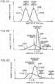
- a number distribution 100F of the diameters of the vents 25F of the first metal sheet 22F and a number distribution 100S of the diameters of the vents 25S of the second metal sheet 22S are both Gaussian distributions having approximately the same half width
- the sag amount of the electrolyte membrane 4 into the vent 25F of the first metal sheet 22F and the sag amount of the electrolyte membrane 4 into the vent 25S of the second metal sheet 22S can be appropriately evaluated.
- the sag amount of the electrolyte membrane 4 into the vent 25F of the first metal sheet 22F can be reduced.
- the half width of the number distribution 100F of the diameters of the vents 25F of the first metal sheet 22F is extremely smaller than the half width of the number distribution 100S of the diameters the vents 25S of the second metal sheet 22S, and the average diameter of the vents 25F of the first metal sheet 22F is larger than the average diameter of the vents 25S of the second metal sheet 22S, by the comparison between the average diameter of the vents 25F and the average diameter of the vents 25S, the sag amount of the electrolyte membrane 4 into the vent 25F of the first metal sheet 22F and the sag amount of the electrolyte membrane 4 into the vent 25S of the second metal sheet 22S may not be appropriately evaluated in some cases.
- the vent 25F of the first metal sheet 22F may reduce the sag amount of the electrolyte membrane 4 as compared to that by the vent 25S of the second metal sheet 22S.
- the sag amount of the electrolyte membrane 4 into the vent 25F and the sag amount of the electrolyte membrane 4 into the vent 25S may be appropriately evaluated as compared to the case evaluated by the comparison between the average diameter of the vents 25F and the average diameter of the vents 25S.
- the number distribution 100S of the diameters of the vents 25S of the second metal sheet 22S is not Gaussian distribution
- the number of vents 25S having a larger diameter is large such that the distribution thereof has a long tail at a right side
- the average diameter of the vents 25F of the first metal sheet 22F is larger than the average diameter of the vents 25S of the second metal sheet 22S
- the sag amount of the electrolyte membrane into the vent 25F of the first metal sheet 22F and the sag amount of the electrolyte membrane into the vent 25S of the second metal sheet 22S may not be appropriately evaluated in some cases.
- the vent 25F of the first metal sheet 22F may reduce the sag amount of the electrolyte membrane 4 as compared to that by the vent 25S of the second metal sheet 22S.
- the sag amount of the electrolyte membrane 4 into the vent 25F and the sag amount of the electrolyte membrane 4 into the vent 25S may be appropriately evaluated as compared to the case evaluated by the comparison between the average diameter of the vents 25F and the average diameter of the vents 25S.
- the number distribution 100F of the diameters of the vents 25F of the first metal sheet 22F and the number distribution 100S of the diameters of the vents 25S of the second metal sheet 22S are shown by way of example and are not limited to this example.
- the first metal sheet 22F has a hardness lower than the hardness of the second metal sheet 22S.
- the hardness of the metal sheet 22 is increased, and as the diameter of the vent of the metal sheet 22 is decreased, processing of the vents of the metal sheet 22 becomes difficult.
- the hardness of the first metal sheet 22F is decreased as compared to the hardness of the second metal sheet 22S, so that fine processing can be easily performed for the vents 25F of the first metal sheet 22F.
- the second metal sheet 22S is formed to have a higher rigidity.
- first metal sheet 22F for example, although aluminum or stainless steel (such as SUS304) may be used, the material is not limited thereto.
- second metal sheet 22S for example, although titanium or stainless steel (such as SUS631) may be used, the material is not limited thereto.
- the electrochemical hydrogen pump 16 of this example may be similar to the electrochemical hydrogen pump 16 of the first embodiment.
- the materials of the first metal sheet 22F and the second metal sheet 22S are described by way of example and are not limited to those of this example.
- one of a pair of primary surfaces of the second metal sheet 22S which is adjacent to the first metal sheet 22F has a roughness higher than the roughness of one of a pair of primary surfaces of the first metal sheet 22F which is adjacent to the anode catalyst layer 3A.
- the other primary surface of the first metal sheet 22F which is adjacent to the second metal sheet 22S has a roughness higher than the roughness of the primary surface of the first metal sheet 22F which is adjacent to the anode catalyst layer 3A.
- the anode gas may be allowed to diffuse between those primary surfaces.
- the gas diffusivity of the first metal sheet 22F is improved.
- the anode gas can be supplied through the gap formed by the irregularities described above.
- the electrochemical hydrogen pump 16 of this modified example may be similar to the electrochemical hydrogen pump 16 of the first embodiment or the example of the first embodiment.
- the electrochemical hydrogen pump 16 of the example of the first embodiment when the hardness of the first metal sheet 22F is set lower than the hardness of the second metal sheet 22S, the irregularities are likely to be formed in the primary surface of the first metal sheet 22F as compared to that in the primary surface of the second metal sheet 22S.
- the first metal sheet 22F of the anode gas diffusion layer 2A is a metal sheet formed of a metal powder sintered body
- the second metal sheet 22S is a laminate formed of metal hard plates.
- the maximum diameter of the vents provided in the first metal sheet 22F formed of a metal sintered body is smaller than the maximum diameter of the vents provided in the second metal sheet 22S of the laminate formed of metal hard plates.
- the average diameter of the vents provided in the first metal sheet 22F formed of a metal sintered body is smaller than the average diameter of the vents provided in the second metal sheet 22S of the laminate formed of metal hard plates.
- the first metal sheet is formed of a metal hard plate
- irregularities (surface roughness) of the surface of the first metal sheet is increased, and the surface area thereof is increased; hence, an area of the first metal sheet in contact with the anode catalyst layer can be further increased. That is, the gas diffusivity to the anode catalyst layer is improved.
- the cathode gas diffusion layer 2C includes a third metal sheet (not shown) which is provided with vents, and the distribution of the average diameters of the vents of the third metal sheet is wider than the distribution of the average diameters of the vents provided in the first metal sheet 22F.
- the first metal sheet 22F may be formed of a metal powder sintered body
- the third metal sheet may be formed of a metal fiber sintered body.
- the distribution of the average diameters of the vents of the third metal sheet can be made wider than the distribution of the average diameters of the vents provided in the first metal sheet 22F.
- the first metal sheet 22F may be formed of a metal mesh
- the second metal sheet 22S may be a laminate formed of metal steel sheets which are provided with vents.
- the size of the vent can be easily decreased, and the porosity can be easily improved.
- the probability in which a pressed electrolyte membrane is ruptured can be not only reduced, but also the area at which the first metal sheet is in contact with the anode catalyst layer can be increased, so that the gas diffusivity can be improved.
- Figs. 7A and 7B are cross-sectional views each showing one example of an anode gas diffusion layer of an electrochemical hydrogen pump of a second embodiment.
- Figs. 7A and 7B each show a partial cross-section of a laminate 20 of an anode gas diffusion layer 2A.
- a first metal sheet 22F and a second metal sheet 22S are provided, in Figs. 7A and 7B , the first metal sheet 22F and the second metal sheet 22S are not shown.
- Figs. 8A, 8B, and 8C are plan views each showing one example of a metal sheet of the laminate of the anode gas diffusion layer.
- At least one metal sheet 22 includes a communication path 23 communicating between through-holes 21.
- the laminate 20 includes metal sheets 22 each having through-holes 21 through which a gas passes.
- at least one metal sheet 22 includes a communication path 23 communicating between through-holes 21.
- the laminate 20 may have any structure.
- the through-holes 21 and pairs of end portions of the communication paths 23 collectively form a gas flow path (hereinafter, referred to as the "standard gas flow path") extending in a direction penetrating the laminate 20, and the communication path 23 forms a gas flow path which is branched from the standard gas flow path and which extends in a direction parallel to a primary surface of the laminate 20 to an adjacent standard gas flow path. Accordingly, the communication path 23 communicates between the through-holes 21 of a metal sheet 22 adjacent to the metal sheet 22 in which the communication path 23 is provided.
- step-wise gas flow path in a gas flow path extending in a step wise manner (hereinafter, referred to as the "step-wise gas flow path), through-holes 21 each forming a through path which extends in a direction penetrating the laminate 20 and communication paths 23 communicating between the through paths of the step-wise gas flow path are provided in the laminate 20. Accordingly, the communication path 23 communicates between the through-holes 21 of metal sheets 22 each adjacent to the metal sheet 22 in which the communication path 23 is provided.
- through-holes 21A may be formed at regular pitches in a longitudinal direction and a lateral direction to have a matrix shape (lattice shape).
- the through-hole 21A may have any shape.
- the through-hole 21A may be, for example, a round hole having a diameter of approximately several tens of micrometers.
- stainless steel such as SUS631
- titanium or the like
- the material is not limited thereto.
- the metal sheet 22A of Fig. 8A does not include the communication path described above.
- through-holes 21B may be formed at regular pitches in a longitudinal direction and a lateral direction.
- the through-hole 21 B may have any shape.
- the through-hole 21B may be, for example, a round hole having a diameter of approximately several tens of micrometers.
- stainless steel such as SUS631
- titanium or the like
- the material is not limited thereto.
- the through-holes 218 are arranged in a longitudinal direction and a lateral direction so that when the centers of adjacent through-holes 21 B are connected to each other, a rhombus S shown by a two-dot chain line is formed.
- a communication path 23B is formed so as to have an opening along an oblique line formed between centers PB of adjacent rhombuses S.
- the communication path 23B extends in a direction parallel to a first direction in which the through-holes 21 B are connected to each other without intersecting the communication path 23B.
- the communication path 23B is formed so as to have an opening along the centers (PB) of straight lines between adjacent through-holes 21 B having a longer distance (between adjacent through-holes 21 B arranged in a longitudinal direction and a lateral direction) among the through-holes 21 B adjacent in a direction different from the first direction.
- the through-holes 21 B and the communication paths 23B are arranged so that the through-holes 21A and the through-holes 21 B are overlapped with each other, and so that the through-holes 21A are overlapped with pairs of end portions of the communication paths 23B.
- the communication path 23B can communicate between the through-holes 21A.
- the communication path 23B may have any shape.
- the through-hole 21 B is a round hole having a diameter of approximately several tens of micrometers
- the communication path 23B may be a slit having a width of approximately several tens of micrometers.
- through-holes 21C may be formed in a metal sheet 22C of the laminate 20, through-holes 21C may be formed.
- the through-holes 21C may have any shape.
- the through-hole 21 C may be, for example, a round hole having a diameter of approximately several tens of micrometers.
- As a material of the metal sheet 22C for example, although stainless steel (SUS631), titanium, or the like may be used, the material is not limited thereto.
- the through-holes 21C are arranged in a longitudinal direction and a lateral direction so that when the centers of adjacent through-holes 21C are connected to each other without intersecting communication paths 23C, an oblique straight line L shown by a two-dot chain line is formed.
- the communication path 23C is formed so as to have an opening along a line between two intermediate points PC which are obtained by equally dividing a straight line between adjacent through-holes 21C in a lateral direction into three segments.
- the through-holes 21C and the communication paths 23C are arranged so that the through-holes 21A and the through-holes 21C are overlapped with each other, and so that the through-holes 21 A are also overlapped with pairs of end portions of the communication paths 23C.
- the communication path 23C can communicate between the through-holes 21A.
- the communication path 23C may have any shape.
- the through-hole 21C is a round hole having a diameter of approximately several tens of micrometers
- the communication path 23C may be a slit having a width of approximately several tens of micrometers.
- the laminate 20 of the anode gas diffusion layer 2A can allow an anode gas to uniformly diffuse as compared to that in the past. That is, since the laminate 20 includes the communication paths 23, the anode gas passing in the laminate 20 can be supplied not only in one direction but also in an arbitrary direction. As a result, when metal sheets 22 having different arrangement patterns of the communication paths 23 are laminated to form the laminate 20, the direction of an anode gas flow in the laminate 20 can be arbitrarily determined. Hence, the gas diffusivity of the anode gas diffusion layer 2A is improved.
- a metal sheet having a different arrangement pattern from that of the metal sheet 22C may be either a metal sheet in which the position of the communication path 23C is shifted in a lateral direction or the metal sheet 22B.
- the anode gas is allowed to flow into the through-hole 21 of the laminate 20 of the anode gas diffusion layer 2A through a gas flow path of a flow path member not shown in the figure
- the laminate 20 does not include the communication path described above
- the anode gas is not allowed to flow into the through-hole 21 of the laminate 20 of the anode gas diffusion layer 2A located above a vertical line to a portion at which no gas flow path of the flow path member is provided, and the gas diffusion in the anode gas diffusion layer 2A may be non-uniformed in some cases.
- the anode gas can be allowed to flow into the through-hole 21 of the laminate 20 of the anode gas diffusion layer 2A as described above through the above communication path 23, the gas diffusion in the anode gas diffusion layer 2A can be suppressed from being non-uniformed.
- reaction overvoltage of the electrochemical hydrogen pump 16 can be suppressed. That is, an increase in reaction resistance (reaction overvoltage) which occurs when hydrogen in the anode gas is dissociated into a proton and an electron, that is, an increase in consumption electrical power required for hydrogen compression operation of the electrochemical hydrogen pump 16, can be suppressed as compared to that in the past.
- the contact area between the metal sheet 22 and the anode catalyst layer 3A is increased.
- the contact area between the first metal sheet 22F and the anode catalyst layer 3A is increased as compared to that of the case in which the anode catalyst layer 3A is adjacent to a metal sheet including the communication paths.
- the diffusion resistance between the first metal sheet 22F and the anode catalyst layer 3A can be appropriately reduced.
- the variation in in-plane fluid resistance of this metal sheet 22 tends to increase.
- the fluid resistance in the former region is decreased as compared to that in the latter region. Accordingly, a gas is likely to flow into the former region as compared to that in the latter region.
- the electrochemical hydrogen pump 16 of this embodiment may be similar to one of the electrochemical hydrogen pumps 16 of the first embodiment, the example of the first embodiment, and the modified examples of the first embodiment.
- the shapes and the dimensions of the through-hole 21 and the communication path 23 are described by way of example and are not limited to those of this example.
- Fig. 9 is a cross-sectional view showing one example of an anode gas diffusion layer of an electrochemical hydrogen pump of a first example of the second embodiment.
- a partial cross-section of a laminate 20 of an anode gas diffusion layer 2A is shown.
- a first metal sheet 22F and a second metal sheet 22S are provided; however, in Fig. 9 , the first metal sheet 22F and the second metal sheet 22S are not shown.
- the communication path 23 communicates between a through-hole 21 LD and a through-hole 21 RD provided in the same metal sheet 22D adjacent to the metal sheet 22 in which the communication path 23 is provided. That is, the communication path 23 communicates between the left-side through-hole 21 LD and the right-side through-hole 21 RD present in the same metal sheet 22D located under the metal sheet 22 in which the communication path 23 is provided.
- the through-hole 21 LD and the through-hole 21 RD are shifted from each other by the length of the communication path 23 in a direction parallel to the primary surface of the laminate 20.
- a metal sheet 22U provided on the metal sheet 22 in which the communication path 23 is provided may include a through-hole 21 U located right above the through-hole 21 LD.
- the communication path 23 communicates between the through-hole 21 U and the through-hole 21 RD.
- the metal sheet 22U located on the metal sheet 22 in which the communication path 23 is provided may include a through-hole (not shown) located right above the through-hole 21 RD. In this case, the communication path 23 communicates between the through-hole located right above as described above and the through-hole 21 Ld.
- the laminate 20 of the anode gas diffusion layer 2A includes the communication path 23 described above, an anode gas passing in the laminate 20 can be supplied not only in a direction penetrating the laminate 20 but also in a direction parallel to the primary surface of the laminate 20. Hence, the gas diffusivity of the anode gas diffusion layer 2A is improved.
- the electrochemical hydrogen pump 16 of this example may be similar to the electrochemical hydrogen pump 16 of the second embodiment.
- Fig. 10 is a cross-sectional view showing one example of an anode gas diffusion layer of an electrochemical hydrogen pump of a second example of the second embodiment.
- a partial cross-section of a laminate 20 of an anode gas diffusion layer 2A is shown.
- a first metal sheet 22F and a second metal sheet 22S are provided, in Fig. 10 , the first metal sheet 22F and the second metal sheet 22S are not shown.
- the communication path 23 communicates between a through-hole 21 U and a through-hole 21 D provided, respectively, in a metal sheet 22U and a metal sheet 22D different therefrom, each of which is adjacent to the metal sheet 22 in which the communication path 23 is provided. That is, the communication path 23 communicates between the through-hole 21 U of the metal sheet 22U located on the metal sheet 22 in which the communication path 23 is provided and the through-hole 21 D of the metal sheet 22D located under the metal sheet 22 described above. In addition, the through-hole 21 U and the through-hole 21 D are shifted from each other by the length of the communication path 23 in a direction parallel to the primary surface of the laminate 20.
- the laminate 20 of the anode gas diffusion layer 2A includes the communication path 23
- a gas passing in the laminate 20 can be supplied not only in a direction penetrating the laminate 20 but also in a direction parallel to the primary surface of the laminate 20.
- the gas diffusivity of the anode gas diffusion layer 2A is improved.
- the electrochemical hydrogen pump 16 of this example may be similar to the electrochemical hydrogen pump 16 of one of the second embodiment and the first example of the second embodiment.
- Fig. 11 is a cross-sectional view showing one example of an anode gas diffusion layer of an electrochemical hydrogen pump of a modified example of the second embodiment.
- Fig. 11 shows a partial cross-section of a laminate 20 of an anode gas diffusion layer 2A.
- a first metal sheet 22F and a second metal sheet 22S are proved, in Fig. 11 , the first metal sheet 22F and the second metal sheet 22S are not shown.
- the laminate 20 of the anode gas diffusion layer 2A includes metal sheets 222 each formed of a metal sintered body which allows a gas to diffuse.
- the metal sheet 222 formed of a metal sintered body is obtained, for example, by sintering a metal powder and has a porous structure formed of a skeleton portion 54 and void portions 53.
- the void portions 53 are spaces each having a diameter of approximately several tens of micrometers (such as approximately 50 ⁇ m) and communicate with each other. Accordingly, when passing through the metal sheet 222 in a thickness direction thereof, an anode gas is allowed to diffuse.
- the metal sheet 222 has a smooth surface by a surface treatment.
- the laminate 20 of the anode gas diffusion layer 2A includes the metal sheets 222 each formed of a metal sintered body, compared to the case in which the laminate 20 is formed of metal steel sheets which are provided with vents and has no metal sheet formed of a metal sintered body, the gas permeability and the gas diffusivity required for the anode gas diffusion layer 2A can be easily secured.
- the electrochemical hydrogen pump 16 of this modified example may be similar to the electrochemical hydrogen pump 16 of one of the first embodiment, the example of the first embodiment, the first to the fourth modified examples of the first embodiment, the second embodiment, and the first and the second examples of the second embodiment.
- the first embodiment, the example of the first embodiment, the first to the fourth modified examples of the first embodiment, the second embodiment, the first and the second examples of the second embodiment, and the modified example of the second embodiment may be performed in combination.
- One aspect of the present disclosure may be used for an electrochemical hydrogen pump which is able to reduce the probability in which an electrolyte membrane pressed to an anode gas diffusion layer by the difference in pressure between a cathode and an anode is ruptured as compared to that in the past.
Landscapes
- Chemical & Material Sciences (AREA)
- Engineering & Computer Science (AREA)
- Chemical Kinetics & Catalysis (AREA)
- Electrochemistry (AREA)
- Organic Chemistry (AREA)
- Materials Engineering (AREA)
- Metallurgy (AREA)
- Oil, Petroleum & Natural Gas (AREA)
- General Chemical & Material Sciences (AREA)
- Analytical Chemistry (AREA)
- Mechanical Engineering (AREA)
- General Engineering & Computer Science (AREA)
- Inorganic Chemistry (AREA)
- Fuel Cell (AREA)
- Electrolytic Production Of Non-Metals, Compounds, Apparatuses Therefor (AREA)
Applications Claiming Priority (1)
| Application Number | Priority Date | Filing Date | Title |
|---|---|---|---|
| JP2017000599 | 2017-01-05 |
Publications (1)
| Publication Number | Publication Date |
|---|---|
| EP3346027A1 true EP3346027A1 (fr) | 2018-07-11 |
Family
ID=60915158
Family Applications (1)
| Application Number | Title | Priority Date | Filing Date |
|---|---|---|---|
| EP17206862.9A Withdrawn EP3346027A1 (fr) | 2017-01-05 | 2017-12-13 | Pompe à hydrogène électrochimique |
Country Status (3)
| Country | Link |
|---|---|
| US (1) | US20180187319A1 (fr) |
| EP (1) | EP3346027A1 (fr) |
| JP (1) | JP2018109221A (fr) |
Cited By (1)
| Publication number | Priority date | Publication date | Assignee | Title |
|---|---|---|---|---|
| EP4570953A1 (fr) * | 2023-12-15 | 2025-06-18 | Sungrow Deutschland GmbH | Multicouches de transport poreux |
Families Citing this family (12)
| Publication number | Priority date | Publication date | Assignee | Title |
|---|---|---|---|---|
| US10893587B2 (en) | 2016-09-23 | 2021-01-12 | Feit Electric Company, Inc. | Light emitting diode (LED) lighting device or lamp with configurable light qualities |
| US9801250B1 (en) | 2016-09-23 | 2017-10-24 | Feit Electric Company, Inc. | Light emitting diode (LED) lighting device or lamp with configurable light qualities |
| US11549187B2 (en) * | 2018-10-18 | 2023-01-10 | Panasonic Intellectual Property Management Co., Ltd. | Electrochemical hydrogen pump |
| JP6876998B1 (ja) * | 2019-07-24 | 2021-05-26 | パナソニックIpマネジメント株式会社 | 圧縮装置 |
| US11564302B2 (en) | 2020-11-20 | 2023-01-24 | Feit Electric Company, Inc. | Controllable multiple lighting element fixture |
| WO2022164896A1 (fr) * | 2021-01-26 | 2022-08-04 | Electric Hydrogen Co. | Couches d'interconnexion dans des cellules électrochimiques |
| JP7193569B2 (ja) | 2021-03-19 | 2022-12-20 | 本田技研工業株式会社 | 電気化学式水素ポンプ |
| US20220307487A1 (en) * | 2021-03-25 | 2022-09-29 | Honda Motor Co., Ltd. | Support member for an electrochemical cell and electrochemical hydrogen compressor |
| JP7496378B2 (ja) * | 2021-03-25 | 2024-06-06 | 本田技研工業株式会社 | 電気化学セルの支持部材及び電気化学式水素ポンプ |
| JP7220742B2 (ja) * | 2021-05-24 | 2023-02-10 | 本田技研工業株式会社 | 電気化学セル、セル運転システム及びセル運転方法 |
| KR102662699B1 (ko) * | 2022-01-21 | 2024-05-03 | 한국에너지기술연구원 | 수전해 스택 |
| JP7421587B2 (ja) | 2022-03-24 | 2024-01-24 | 本田技研工業株式会社 | 電気化学式昇圧セル |
Citations (9)
| Publication number | Priority date | Publication date | Assignee | Title |
|---|---|---|---|---|
| JPS62227097A (ja) * | 1986-03-27 | 1987-10-06 | Agency Of Ind Science & Technol | チタン電極 |
| JP2000058073A (ja) | 1998-08-11 | 2000-02-25 | Toyota Central Res & Dev Lab Inc | 燃料電池 |
| US6361896B1 (en) * | 1996-04-19 | 2002-03-26 | Zentrum Fur Sonnenenergie Und Wasserstoff-Forschung Baden Wuetternberg Gemeinnuetzige Stiftung | Device and method for combined purification and compression of hydrogen containing CO and the use thereof in fuel cell assemblies |
| US20100040926A1 (en) * | 2008-06-23 | 2010-02-18 | Nuvera Fuel Cells, Inc. | Consolidated fuel cell electrode |
| JP4733380B2 (ja) | 2003-12-18 | 2011-07-27 | ハミルトン・サンドストランド・コーポレイション | 高差圧用電気化学セルの電解質支持部材とその製造方法 |
| US20130337366A1 (en) * | 2012-06-13 | 2013-12-19 | Scott Blanchet | Flow structures for use with an electrochemical cell |
| US20150064606A1 (en) * | 2012-03-28 | 2015-03-05 | Nv Bekaert Sa | Assembly of a porous metal diffusion substrate and a polymeric separator membrane |
| US20160049677A1 (en) * | 2014-08-14 | 2016-02-18 | Melicon Gmbh | Gas Diffusion Electrode |
| EP3258524A1 (fr) * | 2016-06-16 | 2017-12-20 | Panasonic Intellectual Property Management Co., Ltd. | Couche de diffusion de gaz et pompe à hydrogène électrochimique |
-
2017
- 2017-09-13 JP JP2017175982A patent/JP2018109221A/ja active Pending
- 2017-11-22 US US15/821,744 patent/US20180187319A1/en not_active Abandoned
- 2017-12-13 EP EP17206862.9A patent/EP3346027A1/fr not_active Withdrawn
Patent Citations (9)
| Publication number | Priority date | Publication date | Assignee | Title |
|---|---|---|---|---|
| JPS62227097A (ja) * | 1986-03-27 | 1987-10-06 | Agency Of Ind Science & Technol | チタン電極 |
| US6361896B1 (en) * | 1996-04-19 | 2002-03-26 | Zentrum Fur Sonnenenergie Und Wasserstoff-Forschung Baden Wuetternberg Gemeinnuetzige Stiftung | Device and method for combined purification and compression of hydrogen containing CO and the use thereof in fuel cell assemblies |
| JP2000058073A (ja) | 1998-08-11 | 2000-02-25 | Toyota Central Res & Dev Lab Inc | 燃料電池 |
| JP4733380B2 (ja) | 2003-12-18 | 2011-07-27 | ハミルトン・サンドストランド・コーポレイション | 高差圧用電気化学セルの電解質支持部材とその製造方法 |
| US20100040926A1 (en) * | 2008-06-23 | 2010-02-18 | Nuvera Fuel Cells, Inc. | Consolidated fuel cell electrode |
| US20150064606A1 (en) * | 2012-03-28 | 2015-03-05 | Nv Bekaert Sa | Assembly of a porous metal diffusion substrate and a polymeric separator membrane |
| US20130337366A1 (en) * | 2012-06-13 | 2013-12-19 | Scott Blanchet | Flow structures for use with an electrochemical cell |
| US20160049677A1 (en) * | 2014-08-14 | 2016-02-18 | Melicon Gmbh | Gas Diffusion Electrode |
| EP3258524A1 (fr) * | 2016-06-16 | 2017-12-20 | Panasonic Intellectual Property Management Co., Ltd. | Couche de diffusion de gaz et pompe à hydrogène électrochimique |
Cited By (1)
| Publication number | Priority date | Publication date | Assignee | Title |
|---|---|---|---|---|
| EP4570953A1 (fr) * | 2023-12-15 | 2025-06-18 | Sungrow Deutschland GmbH | Multicouches de transport poreux |
Also Published As
| Publication number | Publication date |
|---|---|
| JP2018109221A (ja) | 2018-07-12 |
| US20180187319A1 (en) | 2018-07-05 |
Similar Documents
| Publication | Publication Date | Title |
|---|---|---|
| EP3346027A1 (fr) | Pompe à hydrogène électrochimique | |
| US10301179B2 (en) | Electrochemical hydrogen pump | |
| JP6887100B2 (ja) | 膜電極接合体および電気化学式水素ポンプ | |
| EP3306725A1 (fr) | Couche de diffusion de gaz et pompe à hydrogène électrochimique | |
| US10989184B2 (en) | Electrochemical hydrogen pump | |
| JP2017525094A (ja) | 電気化学セルと共に使用するための流れ場 | |
| EP3258524A1 (fr) | Couche de diffusion de gaz et pompe à hydrogène électrochimique | |
| CN104412434A (zh) | 用于燃料电池的气体分布元件 | |
| US20210285427A1 (en) | Electrochemical hydrogen pump | |
| EP3306722A1 (fr) | Dispositif de diffusion de gaz et pompe à hydrogène électrochimique | |
| US8465632B2 (en) | Thin film catalyst on porous media and electrochemical cell employing the same | |
| US20210372379A1 (en) | Compressor | |
| JP2018109217A (ja) | 電気化学式水素ポンプ | |
| CN116209638A (zh) | 压缩装置 | |
| CN111370724B (zh) | 电极分隔板结构及其应用的燃料电池 | |
| JP2018104770A (ja) | ガス拡散デバイスおよび電気化学式水素ポンプ | |
| TWM579825U (zh) | 電極分隔板結構及其應用之燃料電池 | |
| CN113454817A (zh) | 电化学装置 | |
| US12331416B2 (en) | Compression apparatus for hydrogen-containing gas utilizing an anode separator arrangement | |
| JP2024063300A (ja) | 水電解セル | |
| JP2018104788A (ja) | 電気化学式水素ポンプ | |
| EP4455366A1 (fr) | Dispositif de compression | |
| JP2024161631A (ja) | 電気化学式水素ポンプ | |
| JP2019157190A (ja) | 電気化学式水素ポンプ | |
| JP2009277503A (ja) | 燃料電池および燃料電池スタック |
Legal Events
| Date | Code | Title | Description |
|---|---|---|---|
| PUAI | Public reference made under article 153(3) epc to a published international application that has entered the european phase |
Free format text: ORIGINAL CODE: 0009012 |
|
| AK | Designated contracting states |
Kind code of ref document: A1 Designated state(s): AL AT BE BG CH CY CZ DE DK EE ES FI FR GB GR HR HU IE IS IT LI LT LU LV MC MK MT NL NO PL PT RO RS SE SI SK SM TR |
|
| AX | Request for extension of the european patent |
Extension state: BA ME |
|
| STAA | Information on the status of an ep patent application or granted ep patent |
Free format text: STATUS: THE APPLICATION IS DEEMED TO BE WITHDRAWN |
|
| 18D | Application deemed to be withdrawn |
Effective date: 20190112 |