EP3346258B1 - Guide d'onde avec lentille intégrée - Google Patents
Guide d'onde avec lentille intégrée Download PDFInfo
- Publication number
- EP3346258B1 EP3346258B1 EP18151247.6A EP18151247A EP3346258B1 EP 3346258 B1 EP3346258 B1 EP 3346258B1 EP 18151247 A EP18151247 A EP 18151247A EP 3346258 B1 EP3346258 B1 EP 3346258B1
- Authority
- EP
- European Patent Office
- Prior art keywords
- waveguide
- planar surface
- planar
- plano
- lens
- Prior art date
- Legal status (The legal status is an assumption and is not a legal conclusion. Google has not performed a legal analysis and makes no representation as to the accuracy of the status listed.)
- Active
Links
Images




Classifications
-
- G—PHYSICS
- G01—MEASURING; TESTING
- G01N—INVESTIGATING OR ANALYSING MATERIALS BY DETERMINING THEIR CHEMICAL OR PHYSICAL PROPERTIES
- G01N21/00—Investigating or analysing materials by the use of optical means, i.e. using sub-millimetre waves, infrared, visible or ultraviolet light
- G01N21/17—Systems in which incident light is modified in accordance with the properties of the material investigated
- G01N21/55—Specular reflectivity
- G01N21/552—Attenuated total reflection
-
- G—PHYSICS
- G02—OPTICS
- G02B—OPTICAL ELEMENTS, SYSTEMS OR APPARATUS
- G02B6/00—Light guides; Structural details of arrangements comprising light guides and other optical elements, e.g. couplings
- G02B6/10—Light guides; Structural details of arrangements comprising light guides and other optical elements, e.g. couplings of the optical waveguide type
- G02B6/12—Light guides; Structural details of arrangements comprising light guides and other optical elements, e.g. couplings of the optical waveguide type of the integrated circuit kind
- G02B6/122—Basic optical elements, e.g. light-guiding paths
- G02B6/124—Geodesic lenses or integrated gratings
-
- G—PHYSICS
- G02—OPTICS
- G02B—OPTICAL ELEMENTS, SYSTEMS OR APPARATUS
- G02B6/00—Light guides; Structural details of arrangements comprising light guides and other optical elements, e.g. couplings
- G02B6/24—Coupling light guides
- G02B6/42—Coupling light guides with opto-electronic elements
- G02B6/4201—Packages, e.g. shape, construction, internal or external details
- G02B6/4204—Packages, e.g. shape, construction, internal or external details the coupling comprising intermediate optical elements, e.g. lenses, holograms
- G02B6/4206—Optical features
-
- G—PHYSICS
- G02—OPTICS
- G02B—OPTICAL ELEMENTS, SYSTEMS OR APPARATUS
- G02B6/00—Light guides; Structural details of arrangements comprising light guides and other optical elements, e.g. couplings
- G02B6/10—Light guides; Structural details of arrangements comprising light guides and other optical elements, e.g. couplings of the optical waveguide type
- G02B6/12—Light guides; Structural details of arrangements comprising light guides and other optical elements, e.g. couplings of the optical waveguide type of the integrated circuit kind
- G02B2006/12083—Constructional arrangements
- G02B2006/12102—Lens
-
- G—PHYSICS
- G02—OPTICS
- G02B—OPTICAL ELEMENTS, SYSTEMS OR APPARATUS
- G02B6/00—Light guides; Structural details of arrangements comprising light guides and other optical elements, e.g. couplings
- G02B6/10—Light guides; Structural details of arrangements comprising light guides and other optical elements, e.g. couplings of the optical waveguide type
- G02B6/12—Light guides; Structural details of arrangements comprising light guides and other optical elements, e.g. couplings of the optical waveguide type of the integrated circuit kind
- G02B6/12004—Combinations of two or more optical elements
Definitions
- the present invention relates to a waveguide with integrated lens for sample illumination.
- Fluorescently labeled probes provide a convenient method of characterizing the content of biological samples. By tailoring binding chemistry of a fluorescent probe, high specificity can be achieved for detection of complex molecules such as RNA, DNA, proteins, and cellular structures. Since fluorophores typically absorb and re-emit Stokes-shifted radiation regardless of being bound or unbound to a species to be detected, the bound and unbound fluorophores must be separated.
- One common method to separate the bound fluorophores from the unbound fluorophores relies on spatial localization of the fluorescently labeled species. For example, in a 'sandwich immunoassay' a surface is chemically treated to bind a species to be detected to the surface. The fluorescent probes then attach to the species that are bound to the surface. Unbound fluorophores can then be removed from the system with a wash step.
- Total internal reflection fluorescence is one method of reducing background fluorescence.
- TIRF Total internal reflection fluorescence
- TIRF is performed with a laser beam reflecting once from the surface. This is the basis of well established TIRF microscopy and other biosensing techniques. By confining the laser beam inside a waveguide, however, multiple reflections can be realized and larger areas can be illuminated. Several waveguide geometries are possible, each having certain tradeoffs.
- Single-mode planar waveguides also called thin film waveguides or integrated optical waveguides, confine light into a small cross sectional area with the thin dimension smaller than the wavelength of propagating light.
- the advantage of single-mode waveguides is that significantly stronger evanescent fields are generated.
- a disadvantage of single-mode waveguides is that for efficient light coupling, they typically require a prism or grating with precise alignment tolerances.
- single-mode planar waveguides are expensive to manufacture because the guiding layer is typically a thin-film with strict thickness tolerances deposited on a substrate.
- a multimode planar waveguide is substantially easier to couple a laser beam to and simpler to construct than single-mode planar waveguides. For example, a standard 1 millimeter thick microscope slide makes an effective waveguide to which light can be coupled through the edge of the slide. Additionally, dimensions for multimode waveguides are compatible with current plastic injection-molding techniques.
- a uniform evanescent field is desired in the detection region.
- the strength of the evanescent field is uniform along the direction of light propagation for a single-mode planar waveguide (neglecting scattering losses and absorption inside the waveguide).
- cost, robustness, and ease of use are of similar importance.
- uniformity and field strength can be optimized.
- each individual mode in a multimode waveguide has a uniform intensity along the direction of propagation, a distribution of modes will be excited when coupling to a multimode waveguide; this distribution of modes will constructively and destructively interfere on the surface and lead to a spatially varying field strength.
- the mode structure of the waveguide can be neglected, and the intensity in the waveguide can be treated as a conventional diffracting beam that totally-internally reflects from the two surfaces of the waveguide and interferes with neighboring reflections.
- EP 0 209 489 A1 discloses a waveguide apparatus for use in substance analysis having a waveguide, with a surface area in contact with the substance, for transmitting electromagnetic radiation along the axis of the waveguide.
- a waveguide entrance prism is positioned at the radiation entrance end of the waveguide, for guiding radiation into the waveguide.
- the prism has a first face arranged at an angle with the waveguide axis to cause radiation entering the prism to propagate along the waveguide.
- the optical apparatus may include a substrate, an on-substrate microlens coupled with the substrate to receive light from an off-substrate light emitter and focus the light toward a focal point, and an on-substrate optical device coupled with the substrate proximate the focal point to receive the focused light. Communication of light in the reverse direction is also disclosed. Systems including the optical apparatus are also disclosed.
- DE 10 2007 033 124 A1 discloses a device for optical detection of substances in a liquid or gaseous medium, with a substrate with molecules for detecting the substances that are to be detected. These molecules are immobilised at a surface of the substrate or in the substrate and the substances that are to be detected can essentially be selectively bound to these molecules. Light waves can be coupled into the substrate and can be guided through this.
- the substrate is a foil element made of a transparent material in which a coupling structure for coupling the light waves is integrally formed and in which the coupled light waves can be guided.
- DE 103 52 235 A1 discloses a rain sensor which is used to detect humidity on a glass pane.
- Coupling means which are used to couple and/or uncouple radiation emitted by a transmitter in the pane, are provided. Radiation scatters on the pane in several total reflections along a radiation channel. Additional coupling means can be used, in order to enable the recoupled radiation to be decoupled in such a manner that at least one pure scattering area, which does not assist in detection, and one active partial reflection area are formed.
- FIGURE 1 illustrates several examples of existing coupling schemes 105-115 involving multimode waveguides.
- the coupling scheme 105 using a multimode waveguide 120 involves focusing a laser beam 125 that propagates parallel to the waveguide 120 into the edge of the waveguide 120 with a cylindrical lens 130.
- the field strength of a TIR beam is maximized for a beam that is incident at the critical angle and zero for a beam with an incident angle 90° from the surface normal ( i.e., grazing incidence).
- an incident beam that is parallel to the TIR surface will have small evanescent field strength when coupled to the waveguide 120 with the cylindrical lens 130 in the configuration of the scheme 105.
- a variation on the coupling scheme 105 is illustrated by the coupling scheme 110.
- a laser beam 135 focused by a cylindrical lens 140 is incident on the edge of a waveguide 145 with an appropriate angle such that the central ray of the beam 135 inside the waveguide impinges on the surface near the critical angle for TIR to maximize the evanescent field strength.
- a compromise between field strength and uniformity may be made by the choice of focusing optics. If a nearly collimated beam is used to achieve high field intensity by operating near the critical angle for TIR, the beam must make many reflections within the waveguide before the surface intensity becomes sufficiently uniform, thus requiring a longer waveguide. If the beam is highly focused, however, then the surface intensity normalizes in very few reflections, but a significant amount of power is contained in rays propagating outside the critical angle and leads to reduced evanescent field strength down the length of the waveguide.
- a lens 150 is incorporated with a waveguide 155 as a single optical component, made, for example, by bonding the lens element to the planar waveguide or by molding a single optical component. While this allows the focus of the lens 150 to be precisely distanced from the edge of the waveguide 155, careful alignment of a laser beam 160 relative to the lens 150 of the waveguide 155 must still be made to couple the beam 160 to the waveguide 155. For applications requiring repeated placement of a waveguide component relative to the light source, it is highly desirable for the light coupling to be relatively insensitive to misalignment.
- JP S62-254038 A discloses an immunity examination apparatus wherein lights are introduced into a wave guide so as to be reflected from a region performing antigen-antibody reaction and a region performing no antigen-antibody reaction and the difference between both lights led out therefrom is detected.
- the known apparatus comprises two regions parallel to a light propagating direction on the upper surface of a waveguide having a light introducing part and a light lead-out part formed to the under surface thereof at both end parts. In the first region an antibody is fixed to the upper surface of the waveguide and, when a solution containing an antigen is contacted with this first region, antigen-antibody reaction is performed.
- the second region is formed by fixing the antibody 7 at first and subsequently removing the property (preforming antigen-antibody reaction) of the antibody by the irradiation of ultraviolet rays and has the same property as the first region except that no antigen-antibody reaction is performed.
- Lights having the same intensity are introduced from the light introducing part to be respectively reflected by the two regions and guides to a detection part from the light lead-out part and, from the presence and degree of the difference between the intensities of lights reflected by the two regions, the presence and degree of immunity can be detected.
- the known apparatus does not disclose a curved surface for focusing a light beam incident on the curved surface, such that a collimated light beam incident on the curved surface at a propagation vector perpendicular to the normal vector and offset from the planar waveguide in a direction parallel to the normal vector, is focused to and optically coupled to the planar waveguide.
- Embodiments of the present technology provide for sample illumination such as that involved in fluorescence detection and assay based on evanescent fields using apparatus comprising a waveguide with an integrated lens.
- the overall configuration of the apparatus may be such that fluorescence-emitting molecules bound to a waveguide surface are excited by an evanescent field penetrating into the adjacent solution from a light beam propagated within the waveguide, the propagated beam being introduced by an integrally connected lens.
- the collimated beam of light such as a laser beam propagates parallel to the waveguide surface such that the system is insensitive to translation of the waveguide.
- the incident beam is also appropriately offset from the optical axis of the waveguide such that refraction of the light at the lens surface directs the beam into the waveguide at an angle close to the critical angle for TIR.
- a second integrated cylindrical lens may be added to the output end of the waveguide. This may facilitate a second laser being coupled in the opposite direction, such as for multicolor fluorescence assays.
- the apparatus may also allow a fluidic chamber to be bound to the planar waveguide such that the chamber contact with the planar waveguide is outside the optical path of the propagating light, eliminating restrictions on optical properties of material comprising the chamber.
- fluidic chambers have utilized low index of refraction materials in contact with the planar waveguide with mechanical clamping in order to limit optical losses at the waveguide / chamber contact area. By separating the waveguide / chamber contact from the optical path, traditional bonding methods such as adhesives or plastic welding can be used to attach the chamber to the waveguide.
- the fluidic chamber may comprise or be formed in part by a second planar waveguide, wherein the fluidic chamber is disposed between two planar waveguides. In such an arrangement light may be coupled to both planar waveguides as well as the volume formed by the fluidic chamber.
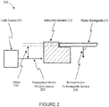
- FIGURE 2A illustrates a generalized configuration 200 descriptive of examples, not being part of the present invention.
- the configuration 200 includes a light source 205, a refractive volume 210, and a planar waveguide 215.
- the light source 205 can include a laser or any other source of collimated or near-collimated light that provides light along a propagation vector 220.
- the refractive volume 210 is positioned proximate to the planar waveguide 215.
- the refractive volume 210 and the planar waveguide 215 may lack a discontinuity in index of refraction therebetween.
- the refractive volume 210 may be adjacent to or abutted to the waveguide 215 with an index matching fluid occupying any gap therebetween.
- the refractive volume 110 may be integrated with the planar waveguide 215 as a single unit or article.
- the planar waveguide 215 is oriented such that the propagation vector 220 is perpendicular to the normal vector 225 of the planar waveguide 215.
- the planar waveguide has an offset 230 in a direction parallel to the normal vector 225 of the planar waveguide 215.
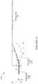
- FIGURE 3 illustrates an exemplary cross-sectional view 300 of a waveguide 305 with an integrated lens 310 according to one embodiment. Additionally, the view 300 depicts a collimated light beam 315 such as that of a laser with a wavelength appropriate to excite fluorescent probes at an assay surface 320.
- the planar waveguide 305 with the associated lens 310 is configured to inject the excitation light 315 through the bottom of the planar waveguide 305.
- a flowcell comprising a sealing mechanism such as a gasket 325, an inlet port 330, an output port 335, and a fluid sample chamber 340 in which chemical compounds deposited on the top surface 320 of the waveguide may bind the desired target compound to the surface.
- Collection and filtering optics 345 can capture fluorescence from the top surface 320 of the waveguide.
- the fluorescence signal can then be directed to an imaging device 350 such as a CCD or CMOS camera.
- an imaging device 350 such as a CCD or CMOS camera.
- the roof, the floor, and/or the walls of the flow cell may be used as a surface on which compounds are deposited.
- the fluidic sample chamber 340 may comprise or be formed in part by a second planar waveguide, similar to the waveguide 305, such that the fluidic sample chamber 340 is disposed between two planar waveguides. In such a configuration, light may be coupled to both planar waveguides as well as the volume formed by the fluidic sample chamber 340.
- the principles described herein are similarly applicable to configurations having multiple planar waveguides.
- FIGURE 4 provides a detailed cross-sectional view 400 of the waveguide 305 with the integrated lens 310.
- FIGURE 5 is a cavalier projection view 500 illustrating the exemplary waveguide 305 with the integrated lens 310.
- the collimated light beam 315 propagates in a direction parallel to the optical axis of the planar waveguide 305, but offset from the optical axis such that it strikes the curved surface of the cylindrical lens 310.
- this geometry may loosen the positional tolerances necessary to couple the collimated light 315 reproducibly to the waveguide 305.
- the light 315 impinges on the curved surface of the lens 310 at a non-zero angle ⁇ relative to the local surface normal of the lens 310, as illustrated in FIGURE 4 .
- the light beam 315 refracts such that it strikes the top surface of the waveguide 305 at an angle ⁇ relative to the optical axis of the waveguide 305.
- the angle ⁇ is defined as the internal propagation angle.
- the vertical distance y between the center of the light beam 315 and the apex of the cylindrical lens 310 is chosen such that ⁇ is less than the complement of the critical angle allowing total internal reflection to occur.
- the curved surface of the lens 310 will act to focus the light beam 315.
- the radius R of the curved surface of the lens 310 is chosen such that for a given beam diameter of the light beam 315, the range of angles incident on the top surface of the waveguide 305 is appropriate to provide a uniform evanescent field strength within the detection region while remaining outside the critical angle for TIR. It may be desired that the light beam 315 focus on the top surface of the waveguide 305 to allow for the greatest tolerance to misalignment.
- the light beam 315 will focus at a horizontal distance L from the center of the circle defining the curved surface of the lens 310.
- the structure comprising the waveguide 305 and lens 310 may be manufactured in several different ways.
- One method is to have the entire assembly constructed in plastic by injection molding technology.
- Geometries such as those described in connection with FIGURE 3 easily allow the adjustment of the internal propagation angle ( ⁇ ) through a translation, rather than a rotation, of the incident laser beam. This allows for a less complicated mechanical design to couple the laser to the waveguide. Additionally, a new injection molded waveguide is not necessary when it is desired to change the incident angle because the focal point of the lens using the disclosed geometry of FIGURES 3 and 4 is very insensitive to the translation of a laser beam relative to the optical axis of the waveguide 305. Further, a desired change in the incident angle is accomplished without changing the readout instrument, allowing variation of cartridge function without physical changes in the instrument. A barcode on the cartridge may be utilized to identify information used to interpret signals from a given cartridge.
- the cylindrical lens 310 is truncated such that it does not extend beyond the location of the focus.
- the area defined by the line connecting the apex of the cylindrical lens 310 and the point on the bottom surface opposite the focus will never have light propagate in it that successfully couples to the waveguide.
- the precise shape of the lens in the area designated optical deadzone 355 can comprise any convenient shape provided the lens 310 does not extend beyond the vertical line passing through the focus. For a single injection molded device where minimizing material costs is important, removing all plastic in the area labeled optical deadzone 355 may be desirable. If two separate components made through conventional optical manufacturing processes are fabricated, a traditional cylindrical lens 310 that has been diced to remove material beyond the focus can be easily manufactured. A material that has low autofluorescence properties may be desirable to minimize background contributions in the signal collection.
- cylindrical lens 310 is used in off-axis geometry, minor optical aberrations at the focus may be exhibited if the curved surface is circular. While a circular profile functionally works, the use of an aspheric surface may be employed to extend the range of the vertical position of the incident beam for which the beam will be coupled to the planar waveguide 305, allowing a larger range of adjustment of the angle ⁇ . The appropriate deviation from a circular profile can be calculated with optical ray tracing programs familiar to those skilled in the art.
- the large area of the top surface of the waveguide 305 before the focus may allow for a sample chamber to be sealed.
- the gasket 325 sealing surface may be absent from the optical path. Therefore, a larger range of gasket materials may be possible that only need to be evaluated for their chemical/biological compatibility and not their optical properties.
- an adhesive backed spacer can be utilized to form a sealed flowcell without a complicated clamping mechanism.
- Multiple flow cells can also be incorporated into a single biosensor by utilizing a gasket with multiple channels.
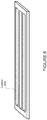
- FIGURE 6 is a cavalier projection view illustrating an exemplary gasket 605 with multiple channels.
- the width of the channel may be chosen to match the unfocused dimension of the incident beam such that light coupling to the gasket along the length of the waveguide is minimized.
- a mechanism for translating the incident beam between channels may be included.
- the top surface of the waveguide 305 within the flow channels may be appropriately treated to allow for the capture of fluorescently labeled target molecules such as proteins, RNA, DNA, or cellular structures.
- a lid attached to the gasket completes the flow cell.
- Fluid samples can be introduced through orifices in the lid and flow through the channels, allowing the fluid to interact with the top waveguide surface.
- Fluid reservoirs exterior to the flow channel can also be included to allow the introduction of fluids into the flow channel and an overflow reservoir at the outlet port of the flow channel to contain the fluid after it has passed through the flow channel.
- the gasket can be optionally eliminated by molding the channels into one of the plastic components and joining the two plastic components directly with methods known to those skilled in the art (e.g., laser or ultrasonic welding).
- the evanescent field created by the light within the waveguide 305 can excite fluorophores that have attached to the top surface of the waveguide 305.
- the emitted light may be captured by a lens or series of lenses (e.g., the collection optics 345 ) to transfer an image of the surface to a plane that is imaged by a light capturing device ( e.g., the imaging device 350 ) such as a CCD or CMOS sensor.
- An optical filter can also be placed between the waveguide surface and the imaging device to eliminate scattered incident light that has not been frequency shifted by the captured fluorophores.
- FIGURE 7 is a flowchart of an exemplary method 700 for performing sample analysis.
- the steps of the method 700 may be performed in varying orders. Furthermore, steps may be added or subtracted from the method 700 and still fall within the scope of the present technology.
- the methodology illustrated in FIGURE 7 may be performed for fluorescence detection and assay based on evanescent fields.
- step 705 light is provided from a light source along a propagation vector.
- the light source can include a laser or any other source of collimated or near-collimated light.
- a refractive volume is illuminated with the light.
- the refractive volume is integrated with a planar waveguide.
- the refractive volume is at least a section of a plano-convex cylindrical lens, wherein the longitudinal axis of the refractive volume is oriented perpendicular to the optical axis and the normal vector of the planar waveguide.
- the light is coupled to the planar waveguide via the refractive volume.
- the waveguide is oriented such that the propagation vector is perpendicular to the normal vector of the planar waveguide and offset from the planar waveguide in a direction parallel to the normal vector of the planar waveguide.
- the optical coupling of the light provided by the light source to the planar waveguide is tuned by translating the light source in a direction parallel to the normal vector of the planar waveguide.
- step 725 consistent optical coupling of the light provided by the light source to the planar waveguide is maintained while translating the light source parallel to the optical axis of the planar waveguide.
- a biological sample is positioned in a reservoir formed at least in part by a face of the planar waveguide.
- step 735 light emitted from a region proximate to a face of the planar waveguide is detected.
- a detector is positioned to detect light emitted from a region proximate to the face of the planar waveguide having a plurality of capture molecules bound thereto.
Landscapes
- Physics & Mathematics (AREA)
- General Physics & Mathematics (AREA)
- Optics & Photonics (AREA)
- Health & Medical Sciences (AREA)
- Life Sciences & Earth Sciences (AREA)
- Chemical & Material Sciences (AREA)
- Analytical Chemistry (AREA)
- Biochemistry (AREA)
- General Health & Medical Sciences (AREA)
- Immunology (AREA)
- Pathology (AREA)
- Engineering & Computer Science (AREA)
- Microelectronics & Electronic Packaging (AREA)
- Investigating, Analyzing Materials By Fluorescence Or Luminescence (AREA)
- Optical Couplings Of Light Guides (AREA)
- Optical Measuring Cells (AREA)
Claims (7)
- Guide d'ondes avec lentille intégrée pour une illumination d'échantillon, comprenant :un guide d'ondes planaire (305) et au moins une section d'une lentille cylindrique plan-convexe (310) formée de manière intégrale avec celui-ci, le guide d'ondes planaire (305) ayant une première surface plane, ladite au moins une section d'une lentille cylindrique plan-convexe (310) ayant (a) une seconde surface plane coplanaire et adjacente à la première surface plane pour former une surface plane commune et (b) une surface courbe,caractérisé en ce que la surface courbe est configurée pour focaliser un faisceau lumineux collimaté (315) incident sur celle-ci, dans lequel le faisceau lumineux collimaté (315) incident sur la surface courbe selon un vecteur de propagation parallèle à l'axe optique du guide d'ondes planaire (305) et décalé par rapport à l'axe optique du guide d'ondes planaire (305) dans une direction perpendiculaire à la surface plane commune est focalisé sur et couplé optiquement au guide d'ondes planaire (305).
- Guide d'ondes avec lentille intégrée selon la revendication 1, dans lequel ladite au moins une section d'une lentille cylindrique plan-convexe (310) est une lentille cylindrique plan-convexe (310) asphérique.
- Guide d'ondes avec lentille intégrée selon la revendication 1, comprenant en outre une chambre fluidique (340), un premier côté de la chambre fluidique (340) étant en butée sur la surface plane commune pour définir un réservoir pour un échantillon biologique, la surface plane commune formant un plancher du réservoir et la première surface plane ayant une pluralité de molécules de capture liées à celle-ci.
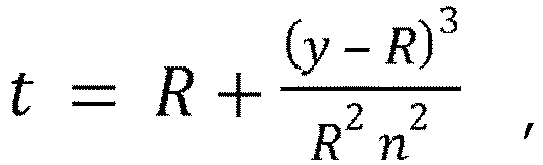
- Guide d'ondes avec lentille intégrée selon la revendication 1, dans lequel (a) ladite au moins une section d'une lentille cylindrique plan-convexe (310) a un indice de réfraction n, (b) la surface courbe a un rayon R, et (c) ladite au moins une section d'une lentille cylindrique plan-convexe (310) a une épaisseur t dans la dimension perpendiculaire à la surface plane commune, de sorte que le faisceau lumineux collimaté (315) est focalisé par la surface courbe pour produire un second faisceau lumineux qui est focalisé sur la surface plane commune et se propage à travers le guide d'ondes planaire via une réflexion interne totale quand (i) le centre du faisceau lumineux collimaté (315) est décalé par rapport au sommet de ladite au moins une section d'une lentille cylindrique plan-convexe (310) à raison d'une distance y dans la direction perpendiculaire à la surface plane commune, dans lequel la distance y est choisie de sorte que l'angle β de propagation est inférieur au complément de l'angle critique permettant une réflexion interne totale, et (ii) t = R + (y - R)3 / (R2n2).
- Guide d'ondes avec lentille intégrée selon la revendication 4, dans lequel ladite au moins une section d'une lentille cylindrique plan-convexe (310) est configurée pour focaliser le faisceau lumineux collimaté (315) à une distance L dans la direction parallèle à l'axe optique du guide d'ondes planaire (305) depuis un centre de cercle défini par la surface courbe, de sorte que, pour un diamètre D du faisceau lumineux collimaté (315), ladite au moins une section de la lentille cylindrique plan-convexe (310) focalise le rayon lumineux collimaté (315) pour produire un second rayon lumineux qui se propage à une plage d'angles β de propagation internes non nuls relativement à la première surface plane,
dans lequel

- Guide d'ondes avec lentille intégrée selon la revendication 5, comprenant en outre une chambre fluidique (340), un premier côté de la chambre fluidique (340) étant en butée sur la surface plane commune pour définir un réservoir pour un échantillon biologique au moins sur la région de détection, la surface plane commune formant un plancher du réservoir et la première surface plane ayant une pluralité de molécules de capture liées à celle-ci.
- Guide d'ondes avec lentille intégrée selon la revendication 5, dans lequel ladite au moins une section de la lentille cylindrique plan-convexe (310) est tronquée de sorte qu'elle ne s'étend pas au-delà de la distance L dans la direction parallèle à l'axe optique du guide d'ondes planaire (305).
Applications Claiming Priority (4)
| Application Number | Priority Date | Filing Date | Title |
|---|---|---|---|
| US15658609P | 2009-03-02 | 2009-03-02 | |
| US12/617,535 US8300993B2 (en) | 2009-03-02 | 2009-11-12 | Waveguide with integrated lens |
| PCT/US2010/025172 WO2010141122A1 (fr) | 2009-03-02 | 2010-02-24 | Guide d'onde doté d'une lentille intégrée |
| EP10783732.0A EP2404203B1 (fr) | 2009-03-02 | 2010-02-24 | Guide d'onde doté d'une lentille intégrée |
Related Parent Applications (1)
| Application Number | Title | Priority Date | Filing Date |
|---|---|---|---|
| EP10783732.0A Division EP2404203B1 (fr) | 2009-03-02 | 2010-02-24 | Guide d'onde doté d'une lentille intégrée |
Publications (2)
| Publication Number | Publication Date |
|---|---|
| EP3346258A1 EP3346258A1 (fr) | 2018-07-11 |
| EP3346258B1 true EP3346258B1 (fr) | 2021-04-21 |
Family
ID=42666932
Family Applications (2)
| Application Number | Title | Priority Date | Filing Date |
|---|---|---|---|
| EP10783732.0A Active EP2404203B1 (fr) | 2009-03-02 | 2010-02-24 | Guide d'onde doté d'une lentille intégrée |
| EP18151247.6A Active EP3346258B1 (fr) | 2009-03-02 | 2010-02-24 | Guide d'onde avec lentille intégrée |
Family Applications Before (1)
| Application Number | Title | Priority Date | Filing Date |
|---|---|---|---|
| EP10783732.0A Active EP2404203B1 (fr) | 2009-03-02 | 2010-02-24 | Guide d'onde doté d'une lentille intégrée |
Country Status (8)
| Country | Link |
|---|---|
| US (1) | US8300993B2 (fr) |
| EP (2) | EP2404203B1 (fr) |
| JP (1) | JP5844644B2 (fr) |
| CN (1) | CN102365566B (fr) |
| BR (1) | BRPI1011472A2 (fr) |
| TW (1) | TW201100776A (fr) |
| WO (1) | WO2010141122A1 (fr) |
| ZA (1) | ZA201106358B (fr) |
Families Citing this family (35)
| Publication number | Priority date | Publication date | Assignee | Title |
|---|---|---|---|---|
| US8331751B2 (en) * | 2009-03-02 | 2012-12-11 | mBio Diagnositcs, Inc. | Planar optical waveguide with core of low-index-of-refraction interrogation medium |
| US9212995B2 (en) | 2009-03-02 | 2015-12-15 | Mbio Diagnostics, Inc. | System and method for detecting multiple molecules in one assay |
| US8300993B2 (en) | 2009-03-02 | 2012-10-30 | Mbio Diagnostics, Inc. | Waveguide with integrated lens |
| US9658222B2 (en) * | 2009-03-02 | 2017-05-23 | Mbio Diagnostics, Inc. | Planar waveguide based cartridges and associated methods for detecting target analyte |
| US20130114076A1 (en) * | 2010-07-09 | 2013-05-09 | Koninklijke Philips Electronics N.V. | Cartridge with large-scale manufacturing design |
| DE102010038431A1 (de) | 2010-07-26 | 2012-01-26 | Diasys Diagnostic Systems Gmbh | Messkassette und Messvorrichtung für die Detektion von Zielmolekülen in einer flüssigen Probe durch Messung von Fluoreszenzemission nach Anregung im evaneszenten Feld |
| TW201217783A (en) * | 2010-09-15 | 2012-05-01 | Mbio Diagnostics Inc | System and method for detecting multiple molecules in one assay |
| DE102010041426A1 (de) * | 2010-09-27 | 2012-05-03 | Siemens Aktiengesellschaft | Messeinheit und Verfahren zur optischen Untersuchung einer Flüssigkeit zur Bestimmung einer Analyt-Konzentration |
| US20120088230A1 (en) * | 2010-10-11 | 2012-04-12 | Monique Givens | System And Method For Cell Analysis |
| US9341504B2 (en) * | 2010-10-11 | 2016-05-17 | Mbio Diagnostics, Inc. | Fluidic assay cartridge with controlled passive flow |
| US10114020B2 (en) | 2010-10-11 | 2018-10-30 | Mbio Diagnostics, Inc. | System and device for analyzing a fluidic sample |
| US20120316077A1 (en) | 2011-06-07 | 2012-12-13 | Charles Greef | System And Method For Detection And Analysis Of A Molecule In A Sample |
| CA2854605A1 (fr) * | 2011-11-04 | 2013-05-10 | Qiaoqiang Gan | Structures de largeur de bande interdite photonique pour dispositifs d'imagerie multispectrale |
| US9024252B2 (en) * | 2012-02-21 | 2015-05-05 | Entegris-Jetalon Solutions, Inc. | Optical sensor apparatus to detect light based on the refractive index of a sample |
| DE102012102983A1 (de) * | 2012-04-05 | 2013-10-10 | Carl Zeiss Microscopy Gmbh | Verfahren und Vorrichtung zum Bestimmen eines kritischen Winkels eines Anregungslichtstrahls |
| GB2506406A (en) | 2012-09-28 | 2014-04-02 | Ibm | Optical adaptor with horizontal and vertical reference surfaces |
| GB2506408A (en) | 2012-09-28 | 2014-04-02 | Ibm | Aligning optical components with optical waveguides using a cavity and two step structures |
| EP2911791A4 (fr) | 2012-10-29 | 2016-11-02 | Mbio Diagnostics Inc | Système d'identification de particules biologiques, cartouche et procédés associés |
| CA2908176A1 (fr) * | 2013-06-03 | 2014-12-11 | Ventana Medical Systems, Inc. | Systeme d'imagerie par fluorescence pour detection de tissu |
| CN104090330B (zh) * | 2014-05-26 | 2017-08-25 | 北京理工大学 | 一种基于集成化自由曲面光学元件的波导显示器 |
| TWM507618U (zh) | 2014-07-04 | 2015-08-21 | Ezconn Corp | 光電微型模組 |
| US9513435B1 (en) * | 2015-10-19 | 2016-12-06 | Laxense Inc. | Hybrid integrated optical device enabling high tolerance optical chip bonding and the method to make the same |
| US10660619B2 (en) | 2017-07-19 | 2020-05-26 | Evanostics Llc | Cartridges for oral fluid analysis and methods of use |
| CA3086538A1 (fr) | 2017-12-15 | 2019-06-20 | Evanostics Llc | Lecteur optique pour test d'analyte |
| DE102018202591A1 (de) * | 2018-02-21 | 2019-08-22 | Robert Bosch Gmbh | Optisches System sowie ein Verfahren zur Herstellung eines optischen Systems |
| EP4550031A3 (fr) * | 2018-04-02 | 2025-07-16 | Magic Leap, Inc. | Guides d'ondes à éléments optiques intégrés |
| US12066383B2 (en) | 2018-12-18 | 2024-08-20 | Aspida Dx Inc. | Optical analyte detection |
| EP3977229A4 (fr) * | 2019-06-03 | 2023-01-18 | SRI International | Réseau neuronal photonique |
| US11391959B2 (en) * | 2019-08-21 | 2022-07-19 | Bae Systems Information And Electronic Systems Integration Inc. | Laser illumination system with closely spaced beams |
| WO2021065996A1 (fr) * | 2019-10-03 | 2021-04-08 | Nsマテリアルズ株式会社 | Appareil d'analyse |
| CN111405735B (zh) * | 2020-04-20 | 2022-04-22 | 深圳市纽尔科技有限公司 | 一种自动焦点定位式舞台追灯追踪系统及其使用方法 |
| CN112629422B (zh) * | 2021-01-07 | 2022-07-08 | 嘉应学院 | 提高散斑法测量精度的误差修正方法及散斑测量方法 |
| DE102021133357A1 (de) | 2021-12-15 | 2023-06-15 | Endress+Hauser Conducta Gmbh+Co. Kg | Sensorelement, Sensorsystem und Verfahren zum Herstellen des Sensorelements |
| CN115290616A (zh) * | 2022-07-28 | 2022-11-04 | 北京交通大学 | 聚合物光波导消逝场传感结构 |
| USD1037522S1 (en) | 2022-11-30 | 2024-07-30 | Eaton Intelligent Power Limited | Floodlight |
Family Cites Families (78)
| Publication number | Priority date | Publication date | Assignee | Title |
|---|---|---|---|---|
| AU557816B2 (en) | 1981-09-18 | 1987-01-08 | Prutec Ltd. | Method for the determination of species in solution with an optical wave-guide |
| DE3588124T2 (de) | 1984-06-13 | 1997-02-20 | Applied Research Systems | Vorrichtung, mit Verwendung in chemischen Prüfverfahren |
| CH665033A5 (fr) | 1985-07-01 | 1988-04-15 | Prutec Ltd | Guide d'onde utilisable comme sonde optique dans l'analyse spectroscopique a reflexion interne. |
| US4852967A (en) | 1986-03-25 | 1989-08-01 | Ciba Corning Diagnostics Corp. | Evanescent wave sensors |
| JPS62254038A (ja) | 1986-04-16 | 1987-11-05 | Daikin Ind Ltd | 免疫検査装置 |
| US4849340A (en) | 1987-04-03 | 1989-07-18 | Cardiovascular Diagnostics, Inc. | Reaction system element and method for performing prothrombin time assay |
| WO1989007756A1 (fr) * | 1988-02-14 | 1989-08-24 | Walter Lukosz | Procede optique integre d'interference |
| JPH0746109B2 (ja) * | 1988-02-29 | 1995-05-17 | ダイキン工業株式会社 | 免疫検査装置および免疫検査方法 |
| JPH0257947A (ja) * | 1988-08-23 | 1990-02-27 | Shimadzu Corp | Atr分光分析用試料セル |
| GB8827853D0 (en) | 1988-11-29 | 1988-12-29 | Ares Serono Res & Dev Ltd | Sensor for optical assay |
| WO1990015985A1 (fr) * | 1989-06-22 | 1990-12-27 | Ares-Serono Research & Development Limited Partnership | Procede d'analyse optique |
| US5604105B1 (en) | 1990-10-12 | 1999-08-24 | Spectral Diagnostics Inc | Method and device for diagnosingand distinguishing chest pain in early onset thereof |
| US5340715A (en) | 1991-06-07 | 1994-08-23 | Ciba Corning Diagnostics Corp. | Multiple surface evanescent wave sensor with a reference |
| US5227134A (en) | 1991-07-29 | 1993-07-13 | Jiri Janata | Dynamic immunochemical and like chemical species sensor apparatus and method |
| EP0620429A4 (fr) * | 1992-10-07 | 1995-02-08 | Daikin Ind Ltd | Dispositif de mesure optique. |
| US5919712A (en) * | 1993-05-18 | 1999-07-06 | University Of Utah Research Foundation | Apparatus and methods for multi-analyte homogeneous fluoro-immunoassays |
| US5512492A (en) * | 1993-05-18 | 1996-04-30 | University Of Utah Research Foundation | Waveguide immunosensor with coating chemistry providing enhanced sensitivity |
| WO1994027137A2 (fr) | 1993-05-18 | 1994-11-24 | University Of Utah Research Foundation | Appareil et procedes d'immuno-essais fluorescents homogenes a analytes multiples |
| US5677196A (en) * | 1993-05-18 | 1997-10-14 | University Of Utah Research Foundation | Apparatus and methods for multi-analyte homogeneous fluoro-immunoassays |
| US5496700A (en) | 1993-08-06 | 1996-03-05 | The United States Of America As Represented By The Secretary Of The Navy | Optical immunoassay for microbial analytes using non-specific dyes |
| JP3326708B2 (ja) * | 1993-08-31 | 2002-09-24 | 日水製薬株式会社 | 光学的測定装置およびその方法 |
| GB9404749D0 (en) * | 1994-03-10 | 1994-04-27 | Ars Holding 89 Nv | Device for use in spectrophotometry |
| JPH07261053A (ja) * | 1994-03-18 | 1995-10-13 | Fujitsu Ltd | 光合分波モジュール |
| JPH07318481A (ja) * | 1994-05-25 | 1995-12-08 | Daikin Ind Ltd | 光学的測定方法およびその装置 |
| DE69526438T2 (de) | 1994-05-27 | 2002-10-31 | Novartis Ag, Basel | Verfahren zum nachweis abklingend angeregter lumineszenz |
| US5599668A (en) | 1994-09-22 | 1997-02-04 | Abbott Laboratories | Light scattering optical waveguide method for detecting specific binding events |
| JPH08145879A (ja) * | 1994-11-25 | 1996-06-07 | Kdk Corp | 過酸化水素の定量方法及びその装置 |
| JP3647470B2 (ja) | 1996-03-19 | 2005-05-11 | ユニバーシティー オブ ユタ リサーチ ファンデーション | 多検体均質蛍光免疫測定法のための振動装置及び方法 |
| US6611634B2 (en) * | 1996-03-19 | 2003-08-26 | University Of Utah Research Foundation | Lens and associatable flow cell |
| CA2248185A1 (fr) | 1996-03-19 | 1997-09-25 | University Of Utah Research Foundation | Lentille et cuve a flux continu associee |
| US6356676B1 (en) | 1996-03-19 | 2002-03-12 | University Of Utah Research Foundation | Lens and associatable flow cell |
| CA2248189C (fr) | 1996-03-19 | 2007-05-29 | University Of Utah Research Foundation | Systeme pour determiner la concentration d'un echantillon a analyser |
| US6287871B1 (en) | 1996-03-19 | 2001-09-11 | University Of Utah Research Foundation | System for determining analyte concentration |
| AU768800B2 (en) | 1996-03-19 | 2004-01-08 | University Of Utah Research Foundation | System for determining analyte concentration |
| US6984491B2 (en) | 1996-07-29 | 2006-01-10 | Nanosphere, Inc. | Nanoparticles having oligonucleotides attached thereto and uses therefor |
| US5832165A (en) | 1996-08-28 | 1998-11-03 | University Of Utah Research Foundation | Composite waveguide for solid phase binding assays |
| US6395558B1 (en) | 1996-08-29 | 2002-05-28 | Zeptosens Ag | Optical chemical/biochemical sensor |
| DE59712460D1 (de) | 1996-11-18 | 2005-12-01 | Novartis Ag | Messvorrichtung mit einem planaren optischen wellenleiter |
| US6686208B2 (en) | 1997-03-18 | 2004-02-03 | Institut Fur Chemo- Und Biosensorik Munster E.V. | Device and method for carrying out fluoresence immunotests |
| US6222619B1 (en) | 1997-09-18 | 2001-04-24 | University Of Utah Research Foundation | Diagnostic device and method |
| US6485905B2 (en) | 1998-02-02 | 2002-11-26 | Signature Bioscience, Inc. | Bio-assay device |
| GB9805935D0 (en) | 1998-03-19 | 1998-05-13 | Ciba Geigy Ag | Organic compounds |
| US6682942B1 (en) | 1998-07-14 | 2004-01-27 | Zyomyx, Inc. | Microdevices for screening biomolecules |
| US6576478B1 (en) | 1998-07-14 | 2003-06-10 | Zyomyx, Inc. | Microdevices for high-throughput screening of biomolecules |
| US6192168B1 (en) * | 1999-04-09 | 2001-02-20 | The United States Of America As Represented By The Secretary Of The Navy | Reflectively coated optical waveguide and fluidics cell integration |
| USD426783S (en) | 1999-04-19 | 2000-06-20 | University Of Utah Research Foundation | Waveguide lens |
| US7056661B2 (en) | 1999-05-19 | 2006-06-06 | Cornell Research Foundation, Inc. | Method for sequencing nucleic acid molecules |
| US6137117A (en) | 1999-06-21 | 2000-10-24 | The United States Of America As Represented By The Secretary Of The Navy | Integrating multi-waveguide sensor |
| US6961490B2 (en) | 2000-01-27 | 2005-11-01 | Unaxis-Balzers Aktiengesellschaft | Waveguide plate and process for its production and microtitre plate |
| JP2003532123A (ja) * | 2000-04-28 | 2003-10-28 | エッジライト バイオサイエンシズ インコーポレイテッド | マイクロアレーエバネッセント波蛍光検出装置 |
| US7142296B2 (en) | 2000-10-30 | 2006-11-28 | Sru Biosystems, Inc. | Method and apparatus for detecting biomolecular interactions |
| US6951715B2 (en) | 2000-10-30 | 2005-10-04 | Sru Biosystems, Inc. | Optical detection of label-free biomolecular interactions using microreplicated plastic sensor elements |
| US7202076B2 (en) | 2000-10-30 | 2007-04-10 | Sru Biosystems, Inc. | Label-free high-throughput optical technique for detecting biomolecular interactions |
| JP3429282B2 (ja) | 2001-02-02 | 2003-07-22 | リサーチ・インターナショナル・インコーポレーテッド | 自動化されたシステム、及びサンプルの分析方法 |
| US6574390B2 (en) | 2001-02-15 | 2003-06-03 | Infineon Technologies Ag | Configuration to multiplex and/or demultiplex the signals of a plurality of optical data channels and method for the production of the configuration |
| JP2003042945A (ja) * | 2001-07-31 | 2003-02-13 | Mitsubishi Heavy Ind Ltd | 表面プラズモン共鳴センサ装置 |
| US6767733B1 (en) | 2001-10-10 | 2004-07-27 | Pritest, Inc. | Portable biosensor apparatus with controlled flow |
| US7189361B2 (en) | 2001-12-19 | 2007-03-13 | 3M Innovative Properties Company | Analytical device with lightguide Illumination of capillary and microgrooves arrays |
| JP3668198B2 (ja) | 2002-02-18 | 2005-07-06 | 株式会社東芝 | 光導波路型マイクロプレート |
| US6954580B2 (en) | 2002-03-01 | 2005-10-11 | Jds Uniphase Corporation | Optical receiver with high dynamic range |
| ATE383572T1 (de) * | 2002-03-18 | 2008-01-15 | Ibidi Gmbh | Probenträger mit integrierter optik |
| JP3968425B2 (ja) * | 2002-11-13 | 2007-08-29 | 独立行政法人産業技術総合研究所 | 光導波路への光導入方法及びそれを用いた光導波路分光測定装置 |
| US6861251B2 (en) | 2003-02-24 | 2005-03-01 | Pritest, Inc. | Translucent solid matrix assay device for microarray analysis |
| WO2005012886A1 (fr) | 2003-03-27 | 2005-02-10 | Corning Incorporated | Detection a champs evanescent et sans etiquette d'agents biologiques et chimiques |
| US20050036728A1 (en) | 2003-08-12 | 2005-02-17 | Henning Braunisch | Curved surface for improved optical coupling between optoelectronic device and waveguide |
| DE10352235A1 (de) | 2003-11-08 | 2005-06-09 | Robert Bosch Gmbh | Regensensor für Glasscheiben, insbesondere für Frontscheiben von Kraftfahrzeugen |
| WO2006025866A2 (fr) | 2004-03-05 | 2006-03-09 | Creatv Microtech, Inc. | Biocapteur a phases multiples integre |
| US7267930B2 (en) * | 2004-06-04 | 2007-09-11 | National Semiconductor Corporation | Techniques for manufacturing a waveguide with a three-dimensional lens |
| US7496245B2 (en) | 2004-08-20 | 2009-02-24 | Research International, Inc. | Misalignment compensating optical sensor and method |
| US7236666B2 (en) | 2004-09-30 | 2007-06-26 | Intel Corporation | On-substrate microlens to couple an off-substrate light emitter and/or receiver with an on-substrate optical device |
| US7268868B2 (en) | 2004-10-29 | 2007-09-11 | Palo Alto Research Center Incorporated | Anti-resonant waveguide sensors |
| JP4679962B2 (ja) * | 2005-05-13 | 2011-05-11 | 株式会社フジクラ | 光センシングシステム |
| WO2007043005A1 (fr) | 2005-10-12 | 2007-04-19 | Koninklijke Philips Electronics N. V. | Capteur optique de guide d'ondes constitue integralement de polymere |
| US7248361B2 (en) | 2005-12-22 | 2007-07-24 | Palo Alto Research Center Incorporated | Fluorescence reader based on anti-resonant waveguide excitation |
| US7522811B2 (en) | 2007-07-13 | 2009-04-21 | Palo Alto Research Center Incorporated | Producing sandwich waveguides |
| US7529438B2 (en) | 2007-07-13 | 2009-05-05 | Palo Alto Research Center Incorporated | Producing fluidic waveguides |
| DE102007033124B4 (de) | 2007-07-16 | 2012-12-06 | Fraunhofer-Gesellschaft zur Förderung der angewandten Forschung e.V. | Vorrichtung zur optischen Detektion von Substanzen in einem flüssigen oder gasförmigen Medium |
| US8300993B2 (en) | 2009-03-02 | 2012-10-30 | Mbio Diagnostics, Inc. | Waveguide with integrated lens |
-
2009
- 2009-11-12 US US12/617,535 patent/US8300993B2/en active Active
-
2010
- 2010-02-12 TW TW099104903A patent/TW201100776A/zh unknown
- 2010-02-24 EP EP10783732.0A patent/EP2404203B1/fr active Active
- 2010-02-24 EP EP18151247.6A patent/EP3346258B1/fr active Active
- 2010-02-24 BR BRPI1011472A patent/BRPI1011472A2/pt not_active Application Discontinuation
- 2010-02-24 JP JP2011552982A patent/JP5844644B2/ja active Active
- 2010-02-24 CN CN201080014792.8A patent/CN102365566B/zh active Active
- 2010-02-24 WO PCT/US2010/025172 patent/WO2010141122A1/fr not_active Ceased
-
2011
- 2011-08-30 ZA ZA2011/06358A patent/ZA201106358B/en unknown
Non-Patent Citations (1)
| Title |
|---|
| None * |
Also Published As
| Publication number | Publication date |
|---|---|
| EP2404203A4 (fr) | 2013-12-11 |
| EP2404203A1 (fr) | 2012-01-11 |
| US20100220318A1 (en) | 2010-09-02 |
| TW201100776A (en) | 2011-01-01 |
| JP5844644B2 (ja) | 2016-01-20 |
| CN102365566B (zh) | 2015-04-01 |
| EP2404203B1 (fr) | 2018-01-17 |
| WO2010141122A1 (fr) | 2010-12-09 |
| US8300993B2 (en) | 2012-10-30 |
| ZA201106358B (en) | 2012-12-27 |
| CN102365566A (zh) | 2012-02-29 |
| EP3346258A1 (fr) | 2018-07-11 |
| JP2012519311A (ja) | 2012-08-23 |
| BRPI1011472A2 (pt) | 2016-03-22 |
Similar Documents
| Publication | Publication Date | Title |
|---|---|---|
| EP2404203B1 (fr) | Guide d'onde doté d'une lentille intégrée | |
| US8606066B2 (en) | Planar optical waveguide with core of low-index-of-refraction interrogation medium | |
| CN102165305B (zh) | 检测系统与方法 | |
| US20120088230A1 (en) | System And Method For Cell Analysis | |
| US20090069199A1 (en) | Method and device for optical detection of substances in a liquid or gaseous medium | |
| US20130114076A1 (en) | Cartridge with large-scale manufacturing design | |
| US20100136709A1 (en) | Receptacle and method for the detection of fluorescence | |
| KR20020015993A (ko) | 통합형 다중-도파관 센서 | |
| WO2002063349A2 (fr) | Guide d'ondes ameliore et procede associe | |
| US20120248347A1 (en) | Confocal optical detector, detector array, and manufacturing method thereof | |
| EP2962086B1 (fr) | Plaque d'échantillons et procédé d'analyse | |
| EP2189782A2 (fr) | Puce à capteur éclairé à réflexion totale | |
| US11366060B2 (en) | Apparatus for detecting fluorescent light emitted from a sample, a biosensor system, and a detector for detecting supercritical angle fluorescent light | |
| EP2535701A2 (fr) | Appareil de détection de fluorescence, cellule d'échantillon pour détecter la fluorescence et procédé de détection de fluorescence | |
| JP2004045046A (ja) | 光学部品ならびに当該光学部品を用いた光検出装置、光検出方法および分析方法 | |
| CN113993455A (zh) | 光学元件或与光学元件有关的改进 | |
| US12000785B2 (en) | Apparatus and method for detecting photoluminescent light emitted from a sample | |
| US20060147347A1 (en) | Method and apparatus for improved light collection | |
| US20110012026A1 (en) | Planar optical waveguide with core of low-index-of-refraction interrogation medium | |
| CA2685574A1 (fr) | Recipient et procede de detection de la fluorescence | |
| JP2005180963A (ja) | 光学分析装置 |
Legal Events
| Date | Code | Title | Description |
|---|---|---|---|
| PUAI | Public reference made under article 153(3) epc to a published international application that has entered the european phase |
Free format text: ORIGINAL CODE: 0009012 |
|
| STAA | Information on the status of an ep patent application or granted ep patent |
Free format text: STATUS: REQUEST FOR EXAMINATION WAS MADE |
|
| 17P | Request for examination filed |
Effective date: 20180111 |
|
| AC | Divisional application: reference to earlier application |
Ref document number: 2404203 Country of ref document: EP Kind code of ref document: P |
|
| AK | Designated contracting states |
Kind code of ref document: A1 Designated state(s): AT BE BG CH CY CZ DE DK EE ES FI FR GB GR HR HU IE IS IT LI LT LU LV MC MK MT NL NO PL PT RO SE SI SK SM TR |
|
| RIN1 | Information on inventor provided before grant (corrected) |
Inventor name: MYATT, CHRISTOPHER Inventor name: MOLL, KEVIN Inventor name: DELANEY, MARIE Inventor name: VOGEL, KURT Inventor name: LOCHHEAD, MICHAEL |
|
| STAA | Information on the status of an ep patent application or granted ep patent |
Free format text: STATUS: EXAMINATION IS IN PROGRESS |
|
| 17Q | First examination report despatched |
Effective date: 20200129 |
|
| GRAP | Despatch of communication of intention to grant a patent |
Free format text: ORIGINAL CODE: EPIDOSNIGR1 |
|
| STAA | Information on the status of an ep patent application or granted ep patent |
Free format text: STATUS: GRANT OF PATENT IS INTENDED |
|
| RIC1 | Information provided on ipc code assigned before grant |
Ipc: G02B 6/42 20060101ALI20201026BHEP Ipc: G01N 21/64 20060101AFI20201026BHEP Ipc: G02B 6/12 20060101ALI20201026BHEP Ipc: G01N 21/552 20140101ALI20201026BHEP |
|
| INTG | Intention to grant announced |
Effective date: 20201125 |
|
| GRAS | Grant fee paid |
Free format text: ORIGINAL CODE: EPIDOSNIGR3 |
|
| GRAA | (expected) grant |
Free format text: ORIGINAL CODE: 0009210 |
|
| STAA | Information on the status of an ep patent application or granted ep patent |
Free format text: STATUS: THE PATENT HAS BEEN GRANTED |
|
| AC | Divisional application: reference to earlier application |
Ref document number: 2404203 Country of ref document: EP Kind code of ref document: P |
|
| AK | Designated contracting states |
Kind code of ref document: B1 Designated state(s): AT BE BG CH CY CZ DE DK EE ES FI FR GB GR HR HU IE IS IT LI LT LU LV MC MK MT NL NO PL PT RO SE SI SK SM TR |
|
| REG | Reference to a national code |
Ref country code: GB Ref legal event code: FG4D |
|
| REG | Reference to a national code |
Ref country code: CH Ref legal event code: EP |
|
| REG | Reference to a national code |
Ref country code: DE Ref legal event code: R096 Ref document number: 602010066863 Country of ref document: DE Ref country code: IE Ref legal event code: FG4D |
|
| REG | Reference to a national code |
Ref country code: AT Ref legal event code: REF Ref document number: 1385149 Country of ref document: AT Kind code of ref document: T Effective date: 20210515 |
|
| REG | Reference to a national code |
Ref country code: LT Ref legal event code: MG9D |
|
| REG | Reference to a national code |
Ref country code: AT Ref legal event code: MK05 Ref document number: 1385149 Country of ref document: AT Kind code of ref document: T Effective date: 20210421 |
|
| REG | Reference to a national code |
Ref country code: NL Ref legal event code: MP Effective date: 20210421 |
|
| PG25 | Lapsed in a contracting state [announced via postgrant information from national office to epo] |
Ref country code: FI Free format text: LAPSE BECAUSE OF FAILURE TO SUBMIT A TRANSLATION OF THE DESCRIPTION OR TO PAY THE FEE WITHIN THE PRESCRIBED TIME-LIMIT Effective date: 20210421 Ref country code: LT Free format text: LAPSE BECAUSE OF FAILURE TO SUBMIT A TRANSLATION OF THE DESCRIPTION OR TO PAY THE FEE WITHIN THE PRESCRIBED TIME-LIMIT Effective date: 20210421 Ref country code: NL Free format text: LAPSE BECAUSE OF FAILURE TO SUBMIT A TRANSLATION OF THE DESCRIPTION OR TO PAY THE FEE WITHIN THE PRESCRIBED TIME-LIMIT Effective date: 20210421 Ref country code: AT Free format text: LAPSE BECAUSE OF FAILURE TO SUBMIT A TRANSLATION OF THE DESCRIPTION OR TO PAY THE FEE WITHIN THE PRESCRIBED TIME-LIMIT Effective date: 20210421 Ref country code: BG Free format text: LAPSE BECAUSE OF FAILURE TO SUBMIT A TRANSLATION OF THE DESCRIPTION OR TO PAY THE FEE WITHIN THE PRESCRIBED TIME-LIMIT Effective date: 20210721 Ref country code: HR Free format text: LAPSE BECAUSE OF FAILURE TO SUBMIT A TRANSLATION OF THE DESCRIPTION OR TO PAY THE FEE WITHIN THE PRESCRIBED TIME-LIMIT Effective date: 20210421 |
|
| PG25 | Lapsed in a contracting state [announced via postgrant information from national office to epo] |
Ref country code: IS Free format text: LAPSE BECAUSE OF FAILURE TO SUBMIT A TRANSLATION OF THE DESCRIPTION OR TO PAY THE FEE WITHIN THE PRESCRIBED TIME-LIMIT Effective date: 20210821 Ref country code: GR Free format text: LAPSE BECAUSE OF FAILURE TO SUBMIT A TRANSLATION OF THE DESCRIPTION OR TO PAY THE FEE WITHIN THE PRESCRIBED TIME-LIMIT Effective date: 20210722 Ref country code: LV Free format text: LAPSE BECAUSE OF FAILURE TO SUBMIT A TRANSLATION OF THE DESCRIPTION OR TO PAY THE FEE WITHIN THE PRESCRIBED TIME-LIMIT Effective date: 20210421 Ref country code: NO Free format text: LAPSE BECAUSE OF FAILURE TO SUBMIT A TRANSLATION OF THE DESCRIPTION OR TO PAY THE FEE WITHIN THE PRESCRIBED TIME-LIMIT Effective date: 20210721 Ref country code: PT Free format text: LAPSE BECAUSE OF FAILURE TO SUBMIT A TRANSLATION OF THE DESCRIPTION OR TO PAY THE FEE WITHIN THE PRESCRIBED TIME-LIMIT Effective date: 20210823 Ref country code: PL Free format text: LAPSE BECAUSE OF FAILURE TO SUBMIT A TRANSLATION OF THE DESCRIPTION OR TO PAY THE FEE WITHIN THE PRESCRIBED TIME-LIMIT Effective date: 20210421 Ref country code: SE Free format text: LAPSE BECAUSE OF FAILURE TO SUBMIT A TRANSLATION OF THE DESCRIPTION OR TO PAY THE FEE WITHIN THE PRESCRIBED TIME-LIMIT Effective date: 20210421 |
|
| REG | Reference to a national code |
Ref country code: DE Ref legal event code: R097 Ref document number: 602010066863 Country of ref document: DE |
|
| PG25 | Lapsed in a contracting state [announced via postgrant information from national office to epo] |
Ref country code: SK Free format text: LAPSE BECAUSE OF FAILURE TO SUBMIT A TRANSLATION OF THE DESCRIPTION OR TO PAY THE FEE WITHIN THE PRESCRIBED TIME-LIMIT Effective date: 20210421 Ref country code: SM Free format text: LAPSE BECAUSE OF FAILURE TO SUBMIT A TRANSLATION OF THE DESCRIPTION OR TO PAY THE FEE WITHIN THE PRESCRIBED TIME-LIMIT Effective date: 20210421 Ref country code: EE Free format text: LAPSE BECAUSE OF FAILURE TO SUBMIT A TRANSLATION OF THE DESCRIPTION OR TO PAY THE FEE WITHIN THE PRESCRIBED TIME-LIMIT Effective date: 20210421 Ref country code: ES Free format text: LAPSE BECAUSE OF FAILURE TO SUBMIT A TRANSLATION OF THE DESCRIPTION OR TO PAY THE FEE WITHIN THE PRESCRIBED TIME-LIMIT Effective date: 20210421 Ref country code: DK Free format text: LAPSE BECAUSE OF FAILURE TO SUBMIT A TRANSLATION OF THE DESCRIPTION OR TO PAY THE FEE WITHIN THE PRESCRIBED TIME-LIMIT Effective date: 20210421 Ref country code: CZ Free format text: LAPSE BECAUSE OF FAILURE TO SUBMIT A TRANSLATION OF THE DESCRIPTION OR TO PAY THE FEE WITHIN THE PRESCRIBED TIME-LIMIT Effective date: 20210421 Ref country code: RO Free format text: LAPSE BECAUSE OF FAILURE TO SUBMIT A TRANSLATION OF THE DESCRIPTION OR TO PAY THE FEE WITHIN THE PRESCRIBED TIME-LIMIT Effective date: 20210421 |
|
| PLBE | No opposition filed within time limit |
Free format text: ORIGINAL CODE: 0009261 |
|
| STAA | Information on the status of an ep patent application or granted ep patent |
Free format text: STATUS: NO OPPOSITION FILED WITHIN TIME LIMIT |
|
| 26N | No opposition filed |
Effective date: 20220124 |
|
| PG25 | Lapsed in a contracting state [announced via postgrant information from national office to epo] |
Ref country code: IS Free format text: LAPSE BECAUSE OF FAILURE TO SUBMIT A TRANSLATION OF THE DESCRIPTION OR TO PAY THE FEE WITHIN THE PRESCRIBED TIME-LIMIT Effective date: 20210821 |
|
| PG25 | Lapsed in a contracting state [announced via postgrant information from national office to epo] |
Ref country code: IT Free format text: LAPSE BECAUSE OF FAILURE TO SUBMIT A TRANSLATION OF THE DESCRIPTION OR TO PAY THE FEE WITHIN THE PRESCRIBED TIME-LIMIT Effective date: 20210421 |
|
| PG25 | Lapsed in a contracting state [announced via postgrant information from national office to epo] |
Ref country code: MC Free format text: LAPSE BECAUSE OF FAILURE TO SUBMIT A TRANSLATION OF THE DESCRIPTION OR TO PAY THE FEE WITHIN THE PRESCRIBED TIME-LIMIT Effective date: 20210421 |
|
| REG | Reference to a national code |
Ref country code: CH Ref legal event code: PL |
|
| REG | Reference to a national code |
Ref country code: BE Ref legal event code: MM Effective date: 20220228 |
|
| PG25 | Lapsed in a contracting state [announced via postgrant information from national office to epo] |
Ref country code: LU Free format text: LAPSE BECAUSE OF NON-PAYMENT OF DUE FEES Effective date: 20220224 |
|
| PG25 | Lapsed in a contracting state [announced via postgrant information from national office to epo] |
Ref country code: LI Free format text: LAPSE BECAUSE OF NON-PAYMENT OF DUE FEES Effective date: 20220228 Ref country code: IE Free format text: LAPSE BECAUSE OF NON-PAYMENT OF DUE FEES Effective date: 20220224 Ref country code: CH Free format text: LAPSE BECAUSE OF NON-PAYMENT OF DUE FEES Effective date: 20220228 |
|
| PG25 | Lapsed in a contracting state [announced via postgrant information from national office to epo] |
Ref country code: BE Free format text: LAPSE BECAUSE OF NON-PAYMENT OF DUE FEES Effective date: 20220228 |
|
| P01 | Opt-out of the competence of the unified patent court (upc) registered |
Effective date: 20230516 |
|
| PG25 | Lapsed in a contracting state [announced via postgrant information from national office to epo] |
Ref country code: HU Free format text: LAPSE BECAUSE OF FAILURE TO SUBMIT A TRANSLATION OF THE DESCRIPTION OR TO PAY THE FEE WITHIN THE PRESCRIBED TIME-LIMIT; INVALID AB INITIO Effective date: 20100224 |
|
| PG25 | Lapsed in a contracting state [announced via postgrant information from national office to epo] |
Ref country code: MK Free format text: LAPSE BECAUSE OF FAILURE TO SUBMIT A TRANSLATION OF THE DESCRIPTION OR TO PAY THE FEE WITHIN THE PRESCRIBED TIME-LIMIT Effective date: 20210421 Ref country code: CY Free format text: LAPSE BECAUSE OF FAILURE TO SUBMIT A TRANSLATION OF THE DESCRIPTION OR TO PAY THE FEE WITHIN THE PRESCRIBED TIME-LIMIT Effective date: 20210421 |
|
| PG25 | Lapsed in a contracting state [announced via postgrant information from national office to epo] |
Ref country code: MT Free format text: LAPSE BECAUSE OF FAILURE TO SUBMIT A TRANSLATION OF THE DESCRIPTION OR TO PAY THE FEE WITHIN THE PRESCRIBED TIME-LIMIT Effective date: 20210421 |
|
| REG | Reference to a national code |
Ref country code: DE Ref legal event code: R082 Ref document number: 602010066863 Country of ref document: DE Representative=s name: WITTE, WELLER & PARTNER PATENTANWAELTE MBB, DE |
|
| REG | Reference to a national code |
Ref country code: DE Ref legal event code: R081 Ref document number: 602010066863 Country of ref document: DE Owner name: MARS, INCORPORATED, MCLEAN, US Free format text: FORMER OWNER: MBIO DIAGNOSTICS INC., BOULDER, CO, US |
|
| PG25 | Lapsed in a contracting state [announced via postgrant information from national office to epo] |
Ref country code: TR Free format text: LAPSE BECAUSE OF FAILURE TO SUBMIT A TRANSLATION OF THE DESCRIPTION OR TO PAY THE FEE WITHIN THE PRESCRIBED TIME-LIMIT Effective date: 20210421 |
|
| PGFP | Annual fee paid to national office [announced via postgrant information from national office to epo] |
Ref country code: GB Payment date: 20260227 Year of fee payment: 17 |
|
| PGFP | Annual fee paid to national office [announced via postgrant information from national office to epo] |
Ref country code: DE Payment date: 20260227 Year of fee payment: 17 |
|
| PGFP | Annual fee paid to national office [announced via postgrant information from national office to epo] |
Ref country code: FR Payment date: 20260225 Year of fee payment: 17 |