EP3346293A1 - Détecteur à double énergie et système d'inspection de rayonnement - Google Patents
Détecteur à double énergie et système d'inspection de rayonnement Download PDFInfo
- Publication number
- EP3346293A1 EP3346293A1 EP17210653.6A EP17210653A EP3346293A1 EP 3346293 A1 EP3346293 A1 EP 3346293A1 EP 17210653 A EP17210653 A EP 17210653A EP 3346293 A1 EP3346293 A1 EP 3346293A1
- Authority
- EP
- European Patent Office
- Prior art keywords
- energy detector
- detector
- detector array
- array
- lower energy
- Prior art date
- Legal status (The legal status is an assumption and is not a legal conclusion. Google has not performed a legal analysis and makes no representation as to the accuracy of the status listed.)
- Withdrawn
Links
Images

Classifications
-
- G—PHYSICS
- G01—MEASURING; TESTING
- G01V—GEOPHYSICS; GRAVITATIONAL MEASUREMENTS; DETECTING MASSES OR OBJECTS; TAGS
- G01V5/00—Prospecting or detecting by the use of ionising radiation, e.g. of natural or induced radioactivity
-
- G—PHYSICS
- G01—MEASURING; TESTING
- G01T—MEASUREMENT OF NUCLEAR OR X-RADIATION
- G01T1/00—Measuring X-radiation, gamma radiation, corpuscular radiation, or cosmic radiation
- G01T1/16—Measuring radiation intensity
- G01T1/20—Measuring radiation intensity with scintillation detectors
- G01T1/2018—Scintillation-photodiode combinations
- G01T1/20182—Modular detectors, e.g. tiled scintillators or tiled photodiodes
-
- G—PHYSICS
- G01—MEASURING; TESTING
- G01N—INVESTIGATING OR ANALYSING MATERIALS BY DETERMINING THEIR CHEMICAL OR PHYSICAL PROPERTIES
- G01N23/00—Investigating or analysing materials by the use of wave or particle radiation, e.g. X-rays or neutrons, not covered by groups G01N3/00 – G01N17/00, G01N21/00 or G01N22/00
- G01N23/02—Investigating or analysing materials by the use of wave or particle radiation, e.g. X-rays or neutrons, not covered by groups G01N3/00 – G01N17/00, G01N21/00 or G01N22/00 by transmitting the radiation through the material
- G01N23/06—Investigating or analysing materials by the use of wave or particle radiation, e.g. X-rays or neutrons, not covered by groups G01N3/00 – G01N17/00, G01N21/00 or G01N22/00 by transmitting the radiation through the material and measuring the absorption
-
- G—PHYSICS
- G01—MEASURING; TESTING
- G01T—MEASUREMENT OF NUCLEAR OR X-RADIATION
- G01T1/00—Measuring X-radiation, gamma radiation, corpuscular radiation, or cosmic radiation
- G01T1/16—Measuring radiation intensity
- G01T1/20—Measuring radiation intensity with scintillation detectors
- G01T1/2018—Scintillation-photodiode combinations
- G01T1/20181—Stacked detectors, e.g. for measuring energy and positional information
-
- G—PHYSICS
- G01—MEASURING; TESTING
- G01T—MEASUREMENT OF NUCLEAR OR X-RADIATION
- G01T1/00—Measuring X-radiation, gamma radiation, corpuscular radiation, or cosmic radiation
- G01T1/16—Measuring radiation intensity
- G01T1/20—Measuring radiation intensity with scintillation detectors
- G01T1/2018—Scintillation-photodiode combinations
- G01T1/20183—Arrangements for preventing or correcting crosstalk, e.g. optical or electrical arrangements for correcting crosstalk
-
- G—PHYSICS
- G01—MEASURING; TESTING
- G01V—GEOPHYSICS; GRAVITATIONAL MEASUREMENTS; DETECTING MASSES OR OBJECTS; TAGS
- G01V5/00—Prospecting or detecting by the use of ionising radiation, e.g. of natural or induced radioactivity
- G01V5/20—Detecting prohibited goods, e.g. weapons, explosives, hazardous substances, contraband or smuggled objects
- G01V5/22—Active interrogation, i.e. by irradiating objects or goods using external radiation sources, e.g. using gamma rays or cosmic rays
Definitions
- the present application relates to the field of radiation inspection, and in particular relates to a dual energy detector and a radiation inspection system.
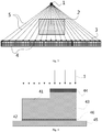
- the radiation beam emitted by a radiation source located on one side of a system after passing through a collimator may form a "sector" beam surface.
- the detector module is located on the other side of the system, and an inspected object is between the radiation beam and the detector module.
- the radiation beam a5 emitted by the radiation source a1 after penetrating the inspected object a2 is emitted towards a plurality of detector modules a4 on a detector module mount a3.
- the existing detector module usually consists of certain amount of higher energy and lower energy detector arrays. All the detector modules are oriented towards a radiation source point.
- the lower energy detector array a41 and the higher energy detector array a45 are generally provided in a front-and-rear positional relation.
- the lower energy detector array a41 is located on one side proximate to the radiation source a1, while the higher energy detector array a45 is disposed on one side distant from the radiation source a1.
- the radiation beam a5 penetrates the lower energy detector array a41 before reaching the higher energy detector array a45.
- the lower energy detector array a41 relatively absorbs more energy of low energy rays
- the higher energy detector array a45 relatively absorbs more high energy rays.
- such two signals are analyzed to obtain information of an effective atomic number of an inspected substance.
- a photodiode a42 and a printed circuit board a43 are provided on a rear side of the lower energy detector array a41, and a photodiode a46 and a printed circuit board a47 are provided on a rear side of the higher energy detector array a45.
- the lower energy detector array a41 in addition to acquiring the low energy signal, also assumes the filtering function of the higher energy detector array a45 by means of a filter a44.
- Each detector module has a fixed orientation at the installation location.
- the orientation is directed to a target point of the radiation source.
- the design is relatively complicated and the installation and debugging are very difficult.
- the entire detector module mount needs to be re-designed.
- the detector module mount needs to be made to be relatively thick, so that it is quite inconvenient in terms of installation and use.
- the detector modules are so unsmooth therebetween that, the detector at an edge of an edge module is susceptible to scattering interference.
- the sensitive medium of the lower energy detector array is limited in an optional range, and thus is not a desirable filtering material.
- the area of the photodiodes on a rear side thereof may generally be less than the area of the lower energy detector array, but does not match the sensitive area of the lower energy detector.
- the width of the radiation beam at the detector module which is difficult to be constrained to the width of a sensitive area of the detector, may generally substantially exceed the width of a single detector array, resulting in an additional radiation protection pressure.
- the present application provides a dual energy detector, comprising: a detector module mount and a plurality of detector modules, the detector module including a higher energy detector array and a lower energy detector array, which are juxtaposedly provided on the detector module mount to be independently irradiated.
- the higher energy detector array and the lower energy detector array in each of the detector modules are disposed such as to be adjacent to each other.
- a plurality of the detector modules are adjacently disposed on a same mounting plane of the detector module mount.
- the plurality of the detector modules are arranged on the detector module mount along a linear sequence.
- a plurality of the detector modules are provided in a plurality of rows on the mounting plane of the detector module mount, each row of the detector modules being adjacently disposed in parallel.
- a heavy metal spacer is provided among various detector units included in the higher energy detector array and/or the lower energy detector array.
- a filter is further provided at one side of the higher energy detector array proximate to a radiation source.
- the density of sensitive medium of the higher energy detector array is higher than that of the lower energy detector array, and/or the effective atomic number of sensitive medium of the higher energy detector array is higher than that of the lower energy detector array.
- the scintillation efficiency of sensitive medium of the lower energy detector array is higher than that of the higher energy detector array.
- the present application provides a radiation inspection system, comprising the aforementioned dual energy detector.
- the present detector provides the higher and lower energy detector arrays in the detector module relative to the same mounting plane of the detector module mount according to a juxtaposed manner, and such structure may simplify the arrangement of the photodiodes and printed circuit boards to which the higher and lower energy detector arrays are connected, such that necessary thickness dimension of the detector module mount is reduced, thereby facilitating the installation and use of the dual energy detector of the present application.
- the radiation beam in the present application may be independently irradiated to the higher and lower energy detector arrays juxtaposed to each other, which reduces to certain extent the mutual restriction during selection of the higher and lower energy detector arrays.
- the radiation source 1 emits the radiation beam 5 to the dual energy detector of the present application to form a beam surface, and the inspected object 2 is disposed in a range covered by the beam surface.
- the dual energy detector includes a detector module mount 3 and a plurality of detector modules 4. The plurality of detector modules 4 are juxtaposedly disposed on the same mounting plane of the detector module mount 3, and the respective various detector modules 4 are oriented parallel to each other.
- the detector modules 4 are more simple in terms of design, installation and debugging on the detector module mount 3, and moreover, the detector module mount 3 is also relatively small in thickness and also relatively light in weight, so that it is also comparatively convenient during the folding or driving of the detector module mount 3.
- a plurality of detector modules 4 are adjacently disposed on the same mounting plane of the detector module mount 3.
- the detector modules 4 are adjacent to each other at an edge position, thereby reducing the scattered light entering the detector modules 4 from the edge position such as to make more smooth transition of the received signals between adjacent detector modules.
- the plurality of the detector modules 4 are arranged on the detector module mount 3 along a linear sequence during design, and such structure only needs to occupy less thickness dimension of the detector module mount 3, and moreover, it is also very convenient during the installation.
- a plurality of the detector modules 4 may also be provided in a plurality of rows on the mounting plane of the detector module mount 3, each row of the detector modules 4 being adjacently disposed in parallel. A plurality of rows of detector modules 4 may effectively improve the scanning speed of the inspected object 2.
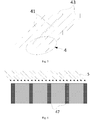
- the detector module 4 includes a higher energy detector array 43 and a lower energy detector array 41, and the higher energy detector array 43 and the lower energy detector array 41 may both formed by sequentially arranging a plurality of detector units. Compared with the front-and-rear arrangement of the lower energy detector array and the higher energy detector array in the existing dual energy detector, the higher energy detector array 43 and the lower energy detector array 41 are juxtaposedly provided relative to a same mounting plane of the detector module mount 3.
- the "high energy” and “low energy” detector arrays are relatively defined in the art.
- the radiation beam is a broad energy spectrum structure, in which partial rays with a low energy are easily absorbed by a substance.
- the higher energy detector array relatively absorbs more high energy radiation portions, while the lower energy detector array relatively absorbs more low energy radiation portions.
- the photodiode 46 below the higher energy detector array 43 is substantially in the same plane as the photodiode 42 below the lower energy detector array 41, and the higher energy detector array 43 and the lower energy detector array 41 share the same printed circuit board 45.
- the maximum thickness of the detector module is the thickness of the higher energy detector array 43 (further plus the thickness of the filter 44, if there is a filter 44) plus the thicknesses of the photodiode 46 and the printed circuit board 45.
- the arrangement manner of the existing dual energy detector determines that the thickness of the detector module is at least a sum of the thicknesses of the higher energy detector array a45 and the lower energy detector array a41, further plus the thicknesses of the photodiode and the printed circuit board connected thereto respectively, so that it is apparent that this is considerably greater than the thickness of the detector module in the present application.
- This further determines that there is a small necessary thickness dimension of the detector module mount in the embodiments of the present application, thereby facilitating the installation and use of the dual energy detector of the present application.
- the radiation beam a5 needs to penetrate the lower energy detector array a41 before reaching the higher energy detector array a45.
- Such irradiation line inevitably affects the selection of the performance of the lower energy detector array a41 and the higher energy detector array a45, especially the low-energy detector array a41.
- the radiation beam 5 in the present application may be independently irradiated to the higher energy detector array 41 and the lower energy detector array 43 juxtaposed to each other, which reduces to certain extent the mutual restriction during selection of the higher and lower energy detector arrays. Further, such arrangement manner may also simplify the adjustment of the energy response and sensitivity to the radiation beam between the higher and lower energy detector arrays.
- the higher energy detector array 43 and the lower energy detector array 41 in each of the detector modules 4 are disposed such as to be adjacent to each other.
- the juxtaposed higher and lower energy detector arrays which may effectuate a large sensitive area of the detector, can match the width of the radiation beam, so as to more effectively utilize the width of the radiation beam, and reduce the radiation protection pressure.
- the density of sensitive medium of the higher energy detector array 43 is higher than the density of sensitive medium of the lower energy detector array 41, and/or the effective atomic number of sensitive medium of the higher energy detector array 43 is higher than the effective atomic number of sensitive medium of the lower energy detector array 41.
- the higher energy detector array is made by choosing a sensitive medium of a higher density and/or effective atomic number, such as to reduce the effects of crosstalk when the rays obliquely irradiate the sensitive medium.
- the scintillation efficiency of sensitive medium of the lower energy detector array 41 is higher than the scintillation efficiency of sensitive medium of the higher energy detector array 43, so as to improve the sensitivity of the lower energy detector array 41.
- a filter 44 may be further provided on a front side of the higher energy detector array 43.
- the lower energy detector array 41 does not possess a filtering function of the higher energy detector array, while the filtering function is realized by the filter 44, such that the filtering function may no longer be considered when the sensitive medium of the lower energy detector array 41 is selected, such as to expand the selection range of the sensitive medium of the lower energy detector array 41.
- the higher energy detector array 43 may choose a proper material and dimension of the filter 44 according to own requirements, so that it is more simple in design. After the filter 44 is added, it is preferable that the sum of the thicknesses of the higher energy detector array 43 and the filter 44 is higher than the thickness of the lower energy detector array 41.
- a heavy metal spacer may also be provided between the detector units.
- a heavy metal spacer 47 provided between various detector units constituting the higher and lower energy detector arrays, may effectively reduce the scattered light scattered from an edge of a detector unit to another detector unit adjacent thereto.
- the aforementioned embodiments of various dual energy detectors may be applied to various fields, especially applied to the radiation inspection system. Therefore, the present application also provides a radiation inspection system comprising any one of the foregoing dual energy detectors for effectuating scanned inspection of an inspected object.
Landscapes
- Physics & Mathematics (AREA)
- Life Sciences & Earth Sciences (AREA)
- General Physics & Mathematics (AREA)
- High Energy & Nuclear Physics (AREA)
- Health & Medical Sciences (AREA)
- Spectroscopy & Molecular Physics (AREA)
- Molecular Biology (AREA)
- Geophysics (AREA)
- General Life Sciences & Earth Sciences (AREA)
- Analytical Chemistry (AREA)
- Pathology (AREA)
- Immunology (AREA)
- General Health & Medical Sciences (AREA)
- Biochemistry (AREA)
- Chemical & Material Sciences (AREA)
- Measurement Of Radiation (AREA)
- Analysing Materials By The Use Of Radiation (AREA)
- Light Receiving Elements (AREA)
Applications Claiming Priority (1)
| Application Number | Priority Date | Filing Date | Title |
|---|---|---|---|
| CN201611205087.1A CN106483153A (zh) | 2016-12-23 | 2016-12-23 | 双能探测器及辐射检查系统 |
Publications (1)
| Publication Number | Publication Date |
|---|---|
| EP3346293A1 true EP3346293A1 (fr) | 2018-07-11 |
Family
ID=58285955
Family Applications (1)
| Application Number | Title | Priority Date | Filing Date |
|---|---|---|---|
| EP17210653.6A Withdrawn EP3346293A1 (fr) | 2016-12-23 | 2017-12-27 | Détecteur à double énergie et système d'inspection de rayonnement |
Country Status (4)
| Country | Link |
|---|---|
| US (1) | US10386502B2 (fr) |
| EP (1) | EP3346293A1 (fr) |
| JP (1) | JP6687590B2 (fr) |
| CN (1) | CN106483153A (fr) |
Families Citing this family (16)
| Publication number | Priority date | Publication date | Assignee | Title |
|---|---|---|---|---|
| JP6717784B2 (ja) * | 2017-06-30 | 2020-07-08 | アンリツインフィビス株式会社 | 物品検査装置およびその校正方法 |
| CN107478664B (zh) * | 2017-09-06 | 2020-06-26 | 奕瑞影像科技(太仓)有限公司 | 线型双能x射线传感器及线型双能x射线检测系统 |
| CN108387593A (zh) * | 2017-12-12 | 2018-08-10 | 北京航星机器制造有限公司 | 一种ct探测装置 |
| CN109946747A (zh) * | 2019-03-25 | 2019-06-28 | 北京航星机器制造有限公司 | 一种基于新型探测装置的双能ct探测系统 |
| KR102278129B1 (ko) * | 2019-12-19 | 2021-07-15 | 오석심 | X-ray 라인 스캔 장치 및 이를 이용한 센서 어레이 모듈의 타일링 방법 |
| DE102020113814A1 (de) | 2020-05-22 | 2021-11-25 | minrocon GmbH | Schüttgutanalysevorrichtung, Schüttguttrennvorrichtung sowie Verfahren zur Analyse und/oder Trennung von Schüttgütern |
| DE102020117484A1 (de) | 2020-07-02 | 2022-01-05 | Smiths Heimann Gmbh | Dual-energie-detektor und aufbereitungsverfahren für detektordaten |
| EP3951436B1 (fr) * | 2020-08-04 | 2025-12-31 | Mettler-Toledo, LLC | Réseau de détecteurs et appareil d'imagerie par absorption comprenant ledit réseau de détecteurs |
| CN112603354A (zh) * | 2020-12-31 | 2021-04-06 | 北京朗视仪器有限公司 | 一种口腔骨密度测量方法及其设备 |
| CN112704511A (zh) * | 2020-12-31 | 2021-04-27 | 北京朗视仪器有限公司 | 一种通过口腔锥形束ct测量骨密度的方法及其设备 |
| CN112704512A (zh) * | 2020-12-31 | 2021-04-27 | 北京朗视仪器有限公司 | 一种通过口腔全景片测量骨密度的方法及其设备 |
| CN113252714A (zh) * | 2021-06-15 | 2021-08-13 | 德瑞科(天津)机械制造有限公司 | 一种具有滤波和防散射的结构及双能ct探测器 |
| CN114397694A (zh) * | 2021-12-21 | 2022-04-26 | 上海奕瑞光电子科技股份有限公司 | 一种x射线双能谱探测线阵探测器 |
| CN115685303A (zh) * | 2022-10-20 | 2023-02-03 | 上海奕瑞光电子科技股份有限公司 | 多能x射线探测器、探测板、成像系统及成像方法 |
| CN115855981A (zh) * | 2022-12-20 | 2023-03-28 | 上海太易检测技术有限公司 | 基于并排结构的双能探测器 |
| CN118276149A (zh) * | 2022-12-26 | 2024-07-02 | 同方威视技术股份有限公司 | 用于探测辐射的探测器 |
Citations (6)
| Publication number | Priority date | Publication date | Assignee | Title |
|---|---|---|---|---|
| US4149081A (en) * | 1976-11-29 | 1979-04-10 | Varian Associates, Inc. | Removal of spectral artifacts and utilization of spectral effects in computerized tomography |
| EP1063538A2 (fr) * | 1999-06-23 | 2000-12-27 | The Nottingham Trent University | Réseau linéaire de détecteurs de scintillations |
| US20070172027A1 (en) * | 2005-12-31 | 2007-07-26 | Yuanjing Li | Multi-array detector module structure for radiation imaging |
| US20100284515A1 (en) * | 2009-05-08 | 2010-11-11 | Neeraj Agrawal | Apparatus for Bone Density Assessment and Monitoring |
| US20120236987A1 (en) * | 2011-03-18 | 2012-09-20 | David Ruimi | Multiple energy ct scanner |
| EP3029452A1 (fr) * | 2013-07-29 | 2016-06-08 | Nuctech Company Limited | Détecteurs dans un agencement de hachage pour dispositif d'inspection de conteneur/véhicule à rayons x/gamma |
Family Cites Families (17)
| Publication number | Priority date | Publication date | Assignee | Title |
|---|---|---|---|---|
| JPS6271881A (ja) * | 1985-09-26 | 1987-04-02 | Toshiba Corp | 放射線検出器 |
| JPH03273687A (ja) * | 1990-03-22 | 1991-12-04 | Matsushita Electric Ind Co Ltd | 放射線吸収材料および放射線検出器 |
| US5841833A (en) * | 1991-02-13 | 1998-11-24 | Lunar Corporation | Dual-energy x-ray detector providing spatial and temporal interpolation |
| JP2001264495A (ja) * | 2000-03-16 | 2001-09-26 | Fuji Photo Film Co Ltd | 放射線エネルギー分離フィルタ、固体センサおよびこれらを用いた放射線画像情報取得装置並びに放射線画像情報取得方法 |
| US9113839B2 (en) * | 2003-04-25 | 2015-08-25 | Rapiscon Systems, Inc. | X-ray inspection system and method |
| US7388208B2 (en) * | 2006-01-11 | 2008-06-17 | Ruvin Deych | Dual energy x-ray detector |
| JP5566218B2 (ja) * | 2010-08-11 | 2014-08-06 | 株式会社トクヤマ | フッ化物単結晶、真空紫外発光素子、シンチレーター及びフッ化物単結晶の製造方法 |
| RU2589252C2 (ru) * | 2011-02-03 | 2016-07-10 | Конинклейке Филипс Н.В. | Чувствительные к вертикальному излучению детекторы одной или многих энергий |
| DE102011053971A1 (de) * | 2011-09-27 | 2013-03-28 | Wipotec Wiege- Und Positioniersysteme Gmbh | Verfahren und Vorrichtung zum Erfassen der Struktur von bewegten Stückgütern, insbesondere zur Erfassung von Störpartikeln in flüssigen oder pastösen Produkten |
| ES1154460Y (es) * | 2012-02-14 | 2016-07-08 | American Science & Eng Inc | Dispositivo de portal de inspección por rayos X |
| JP5726271B2 (ja) * | 2013-11-08 | 2015-05-27 | 浜松ホトニクス株式会社 | 放射線検出装置、放射線画像取得システム、放射線検査システム、及び放射線検出方法 |
| CN104749199B (zh) * | 2013-12-30 | 2019-02-19 | 同方威视技术股份有限公司 | 双能/双视角的高能x射线透视成像系统 |
| JP6274939B2 (ja) * | 2014-03-26 | 2018-02-07 | アンリツインフィビス株式会社 | X線検査装置 |
| CN106255900A (zh) * | 2014-04-30 | 2016-12-21 | 模拟技术公司 | 用于成像模式的探测器阵列 |
| EP3202874B1 (fr) * | 2014-09-30 | 2020-07-01 | Hitachi Metals, Ltd. | Matière fluorescente, scintillateur, réseau scintillateur et détecteur de rayonnement |
| CN105510363B (zh) * | 2015-12-29 | 2019-05-07 | 同方威视技术股份有限公司 | 双能探测器装置、系统及方法 |
| CN206369708U (zh) * | 2016-12-23 | 2017-08-01 | 同方威视技术股份有限公司 | 双能探测器及辐射检查系统 |
-
2016
- 2016-12-23 CN CN201611205087.1A patent/CN106483153A/zh active Pending
-
2017
- 2017-12-25 JP JP2017248501A patent/JP6687590B2/ja active Active
- 2017-12-26 US US15/853,961 patent/US10386502B2/en active Active
- 2017-12-27 EP EP17210653.6A patent/EP3346293A1/fr not_active Withdrawn
Patent Citations (6)
| Publication number | Priority date | Publication date | Assignee | Title |
|---|---|---|---|---|
| US4149081A (en) * | 1976-11-29 | 1979-04-10 | Varian Associates, Inc. | Removal of spectral artifacts and utilization of spectral effects in computerized tomography |
| EP1063538A2 (fr) * | 1999-06-23 | 2000-12-27 | The Nottingham Trent University | Réseau linéaire de détecteurs de scintillations |
| US20070172027A1 (en) * | 2005-12-31 | 2007-07-26 | Yuanjing Li | Multi-array detector module structure for radiation imaging |
| US20100284515A1 (en) * | 2009-05-08 | 2010-11-11 | Neeraj Agrawal | Apparatus for Bone Density Assessment and Monitoring |
| US20120236987A1 (en) * | 2011-03-18 | 2012-09-20 | David Ruimi | Multiple energy ct scanner |
| EP3029452A1 (fr) * | 2013-07-29 | 2016-06-08 | Nuctech Company Limited | Détecteurs dans un agencement de hachage pour dispositif d'inspection de conteneur/véhicule à rayons x/gamma |
Also Published As
| Publication number | Publication date |
|---|---|
| US20180180746A1 (en) | 2018-06-28 |
| JP2018105864A (ja) | 2018-07-05 |
| JP6687590B2 (ja) | 2020-04-22 |
| CN106483153A (zh) | 2017-03-08 |
| US10386502B2 (en) | 2019-08-20 |
Similar Documents
| Publication | Publication Date | Title |
|---|---|---|
| EP3346293A1 (fr) | Détecteur à double énergie et système d'inspection de rayonnement | |
| EP2960686B1 (fr) | Dispositif de détection, système de tomodensitométrie biénergétique et procédé de détection utilisant le système | |
| WO2004072679A3 (fr) | Systeme de tomographie monophotonique d'emission | |
| US9218933B2 (en) | Low-dose radiographic imaging system | |
| RU2009123014A (ru) | Детектор излучения с несколькими электродами на чувствительном слое | |
| CN102109473B (zh) | 利用光中子透射对物体成像的方法及探测器阵列 | |
| US20140355734A1 (en) | Anti-scatter collimators for detector systems of multi-slice x-ray computed tomography systems | |
| CN102446573A (zh) | X射线的混合准直器及其制作方法 | |
| WO2011097386A1 (fr) | Systèmes de détection de faisceau en éventail multi-inverse à plans multiples et procédé d'utilisation associé | |
| US20170184515A1 (en) | Dual-energy detection apparatus, system and method | |
| CN110325846B (zh) | 采用衍射检测器的样本检查设备 | |
| WO2019042797A1 (fr) | Détecteur multicouche à scintillateur monolithique | |
| CN101404939A (zh) | 基于双源扫描的电离辐射检测 | |
| CA3055351C (fr) | Systeme et methode de detection aux rayons x | |
| US20230380781A1 (en) | X-Ray Detection Structure and System | |
| CN208314216U (zh) | 一种双能量x射线探测器 | |
| CN107478664B (zh) | 线型双能x射线传感器及线型双能x射线检测系统 | |
| US20050236574A1 (en) | Detector module for detecting X-radiation | |
| CN209280934U (zh) | 一种双能探测器及平面探测器 | |
| CN206369708U (zh) | 双能探测器及辐射检查系统 | |
| CN215179814U (zh) | 一种具有滤波和防散射的结构及双能ct探测器 | |
| CN103957804B (zh) | X射线ct装置以及x射线ct装置用的数据检测系统 | |
| EP3951436B1 (fr) | Réseau de détecteurs et appareil d'imagerie par absorption comprenant ledit réseau de détecteurs | |
| EP1173856B1 (fr) | Procede et appareil destines a l'alignement simplifie dans des images radiologiques | |
| CN208459303U (zh) | 透射检查设备 |
Legal Events
| Date | Code | Title | Description |
|---|---|---|---|
| PUAI | Public reference made under article 153(3) epc to a published international application that has entered the european phase |
Free format text: ORIGINAL CODE: 0009012 |
|
| 17P | Request for examination filed |
Effective date: 20180117 |
|
| AK | Designated contracting states |
Kind code of ref document: A1 Designated state(s): AL AT BE BG CH CY CZ DE DK EE ES FI FR GB GR HR HU IE IS IT LI LT LU LV MC MK MT NL NO PL PT RO RS SE SI SK SM TR |
|
| AX | Request for extension of the european patent |
Extension state: BA ME |
|
| RBV | Designated contracting states (corrected) |
Designated state(s): AL AT BE BG CH CY CZ DE DK EE ES FI FR GB GR HR HU IE IS IT LI LT LU LV MC MK MT NL NO PL PT RO RS SE SI SK SM TR |
|
| STAA | Information on the status of an ep patent application or granted ep patent |
Free format text: STATUS: THE APPLICATION HAS BEEN WITHDRAWN |
|
| 18W | Application withdrawn |
Effective date: 20210112 |