EP3347980B1 - Verfahren zur steuerung einer generatorspannung - Google Patents
Verfahren zur steuerung einer generatorspannung Download PDFInfo
- Publication number
- EP3347980B1 EP3347980B1 EP15770554.2A EP15770554A EP3347980B1 EP 3347980 B1 EP3347980 B1 EP 3347980B1 EP 15770554 A EP15770554 A EP 15770554A EP 3347980 B1 EP3347980 B1 EP 3347980B1
- Authority
- EP
- European Patent Office
- Prior art keywords
- band
- synchronous generator
- power system
- voltage
- rejection filter
- Prior art date
- Legal status (The legal status is an assumption and is not a legal conclusion. Google has not performed a legal analysis and makes no representation as to the accuracy of the status listed.)
- Active
Links
Images



Classifications
-
- H—ELECTRICITY
- H02—GENERATION; CONVERSION OR DISTRIBUTION OF ELECTRIC POWER
- H02P—CONTROL OR REGULATION OF ELECTRIC MOTORS, ELECTRIC GENERATORS OR DYNAMO-ELECTRIC CONVERTERS; CONTROLLING TRANSFORMERS, REACTORS OR CHOKE COILS
- H02P9/00—Arrangements for controlling electric generators for the purpose of obtaining a desired output
- H02P9/14—Arrangements for controlling electric generators for the purpose of obtaining a desired output by variation of field
- H02P9/26—Arrangements for controlling electric generators for the purpose of obtaining a desired output by variation of field using discharge tubes or semiconductor devices
- H02P9/30—Arrangements for controlling electric generators for the purpose of obtaining a desired output by variation of field using discharge tubes or semiconductor devices using semiconductor devices
- H02P9/302—Brushless excitation
-
- H—ELECTRICITY
- H02—GENERATION; CONVERSION OR DISTRIBUTION OF ELECTRIC POWER
- H02P—CONTROL OR REGULATION OF ELECTRIC MOTORS, ELECTRIC GENERATORS OR DYNAMO-ELECTRIC CONVERTERS; CONTROLLING TRANSFORMERS, REACTORS OR CHOKE COILS
- H02P9/00—Arrangements for controlling electric generators for the purpose of obtaining a desired output
- H02P9/10—Control effected upon generator excitation circuit to reduce harmful effects of overloads or transients, e.g. sudden application of load, sudden removal of load, sudden change of load
-
- G—PHYSICS
- G01—MEASURING; TESTING
- G01R—MEASURING ELECTRIC VARIABLES; MEASURING MAGNETIC VARIABLES
- G01R23/00—Arrangements for measuring frequencies; Arrangements for analysing frequency spectra
- G01R23/02—Arrangements for measuring frequency, e.g. pulse repetition rate; Arrangements for measuring period of current or voltage
Definitions
- the disclosure relates generally to an electrical power system comprising one or more synchronous generators. More particularly, the disclosure relates to a method for controlling the excitation of a synchronous generator, and to a voltage regulator for controlling the excitation of a synchronous generator. Furthermore, the disclosure relates to a computer program for configuring a voltage regulator of an electrical power system.
- an electrical power system for producing electrical energy comprises one or more prime movers arranged to rotate one or more synchronous generators.
- Each prime mover can be for example a turbine or a piston engine such as a diesel engine.
- the electrical power system comprises an excitation device configured to supply excitation current to the rotor winding of the synchronous generator under consideration.
- the excitation device can be for example a contactless rotating exciter or a slip-ring exciter.
- a control system of each synchronous generator comprises a voltage regulator for controlling the excitation device.
- the voltage regulator is often called an automatic voltage regulator "AVR".
- the voltage regulator is a part of a voltage control loop for controlling the excitation of the synchronous generator on the basis of actual and reference values of the amplitude of the generator voltage.
- a control system of a synchronous generator may further comprise a power system stabilizer "PSS" in parallel with the voltage regulator in order to enhance the dynamic stability of the electrical power system.
- Power system stabilizers have been shown to be effective in damping oscillations where instantaneous powers of synchronous generators or groups of synchronous generators oscillate with respect to each other. The frequency area of these oscillations can be e.g. from 0.3 Hz to 2 Hz.
- a power system stabilizer comprises typically a lead-lag circuit for modifying a signal indicative of deviation from synchronous operation, e.g. a signal indicative of deviation of a measured rotation speed from the nominal rotational speed.
- the lead-lag circuitry provides a phase-lead at the frequency area of the above-mentioned oscillations, and thus the lead-lag circuitry provides a good phase-margin on this frequency area. Therefore, the power system stabilizer "PSS" can be tuned to effectively suppress the above-mentioned oscillations.
- a control system of the kind described above is, however, not free from challenges.
- the power system stabilizer "PSS" may have an inverse effect on the damping of torsional mode oscillations that may occur in a rotating system comprising the rotor of a synchronous generator and a rotating part of a turbine or another prime mover.
- the prime mover is a four-stroke piston engine
- the lowest frequency component that is excited due to the nature of the engine is the half rotation frequency that is N/(2 ⁇ 60), where N is the rotational speed as revolutions per minute.
- Another frequency that can be harmful is the lowest natural torsion oscillation frequency.
- This natural frequency can be estimated by modelling the combination of the rotor of the synchronous generator and the rotating part of the prime mover as a two mass system comprising a flexible coupling.
- the above-mentioned natural frequency is: 1 2 ⁇ K c J M + J G J M J G , where Kc is the torsional elastic constant of the flexible coupling, J G is the moment of inertia of the rotor of the synchronous generator, and J M is the moment of inertia of the rotating part of the prime mover.
- Publications US4080559 and US4788653 describe control systems where a power system stabilizer "PSS" comprises a band-rejection filter.
- the stop-band of the band-rejection filter is arranged to cover the frequency area of the torsional mode oscillations.
- the band-rejection filter suppresses the frequency components related to the torsional mode oscillations, and therefore the adverse phenomenon where the power system stabilizer maintains or even amplifies the torsional mode oscillations can be avoided.
- Publication DE102008043203 describes a filter mechanism for filtering a generator output signal and exhibiting a pre-set filter characteristic e.g. band pass characteristic, with a cut-off frequency.
- a detection mechanism detects a frequency of the filtered output signal.
- An adaptation mechanism adapts the cut-off frequency of the filter mechanism depending on the detected frequency.
- FIG. 1a illustrates an electrical power system according to an exemplifying and non-limiting embodiment of the invention.
- the electrical power system can be, for example but not necessarily, an electrical power system of a ship or a diesel power plant.
- the electrical power system comprises a synchronous generator 101 that is driven by a prime mover 112.
- the synchronous generator 101 is configured to supply electrical power to a power grid 118.
- the prime mover 112 can be for example a diesel engine.
- An excitation device 124 is configured to supply excitation current to the rotor winding of the synchronous generator 101.
- the excitation device 124 can be for example a contactless rotating exciter or a slip-ring exciter.
- the electrical power system comprises a signal transducer 102 for producing an amplitude signal 113 indicative of the amplitude of the three-phase stator voltage of the synchronous generator 101.
- the amplitude signal 113 can be for example the length, i.e. the norm, of a space vector of the three-phase stator voltage.
- the amplitude signal 113 is substantially: 2 3 abs u a + a u b + a 2 u c , where u a , u b , and u c are instantaneous values of the stator phase voltages of the synchronous generator 101, a is a complex number (-1 + iV3)/2, and "abs" means the absolute value.
- the electrical power system comprises a band-rejection filter 104 having a stop-band that covers at least partly a frequency area of torsional mode oscillations that may take place in a rotating system that comprises the rotor of the synchronous generator 101 and a rotating part of the prime mover 112.
- the lower corner frequency of the above-mentioned stop-band can be for example on the range from 30 % to 70 % of f s /2p and the upper corner frequency of the stop-band can be on the range from 80 % to 150 % of the f s /2p, where f s is the nominal frequency of the voltage of the synchronous generator, typically 50 Hz or 60 Hz, and p is the number of pole pairs of the synchronous generator.
- f s /2p is the nominal half rotation frequency of the synchronous generator.
- the corner frequencies may represent e.g. a 3 dB suppression level.
- the band-rejection filter 104 is configured to output a filtered amplitude signal 114, and a subtraction element 115 is configured to form a difference 117 between the reference amplitude 116 of the generator voltage and the filtered amplitude signal 114.
- the filtered amplitude signal 114 is illustrated in figure element 122 in figure 1b . In the exemplifying situation presented in figure 1b , the filtered amplitude signal 114 is substantially constant.
- the electrical power system comprises a controller 103 for controlling the excitation device 124 on the basis of the above-mentioned difference 117.
- the controller 103 can be configured to carry out for example proportional P control, proportional and integrative PI control, proportional, integrative, and derivative PID control, or some other suitable control functionality.
- the signal transducer 102, the band-rejection filter 104, and the controller 103 are parts of a voltage control loop for controlling the excitation of the synchronous generator 101 on the basis of the amplitude signal 113 and the reference amplitude 116.
- the voltage control loop is illustrated with the aid of a dashed curve 119.
- the voltage control loop comprises the band-rejection filter 104, frequency components related to the torsional mode oscillations are suppressed in the voltage control loop and therefore adverse phenomena where the voltage control loop maintains or even amplifies the torsional mode oscillations can be avoided.
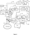
- FIG. 2 illustrates an electrical power system according to an exemplifying and non-limiting embodiment of the invention.
- the electrical power system comprises a synchronous generator 101, a signal transducer 102 for producing an amplitude signal 113 indicative of the amplitude of the voltage of the synchronous generator, and a controller 103 for controlling an excitation device 124 connected to the synchronous generator.
- the signal transducer 102 and the controller 103 are parts of a voltage control loop 119 for controlling the excitation of the synchronous generator on the basis of the amplitude signal 113 and the reference amplitude 116 of the generator voltage.
- the voltage control loop 119 further comprises a band-rejection filter 104.
- the stop-band of the band-rejection filter covers at least partly the frequency area of torsional mode oscillations of a rotating system comprising the rotor of the synchronous generator 101 and a rotating part of a prime mover 112.
- the voltage control loop further comprises a low-pass filter 206 for damping high-frequency signal components from the amplitude signal 113 and thereby high-frequency amplitude oscillations from the voltage of the synchronous generator 101.
- the exemplifying electrical power system illustrated in figure 2 comprises a power system stabilizer "PSS" 207 that receives a speed signal 225 from a speed sensor 223.
- the speed signal 225 is indicative of a measured rotational speed of the synchronous generator 101.
- the power system stabilizer 207 comprises typically a lead-lag circuitry for providing a phase-lead at a frequency area where the power system stabilizer is capable of damping oscillations.
- the power system stabilizer 207 is configured to form a stabilizing signal 226 on the basis of deviation of the measured rotational speed from the nominal rotational speed. At least a part of the information contained by the stabilizing signal 226 is conducted to the controller 103 via a summation element 229.
- the power system stabilizer 207 and the controller 103 are parts of a stabilizing control loop for controlling the excitation of the synchronous generator 101 on the basis of the deviation of the measured rotational speed from the nominal rotational speed.
- the stabilizing control loop is illustrated with a dashed curve 228.
- the stabilizing control loop 228 further comprises a band-rejection filter 204 having a stop-band covering at least partly the frequency area of the torsional mode oscillations of the rotating system.
- the band-rejection filter 204 suppresses the frequency components related to the torsional mode oscillations, and therefore the adverse phenomenon where the power system stabilizer 207 maintains or even amplifies the torsional mode oscillations can be avoided.
- the band-rejection filter 104 comprises one or more controllable components for implementing a changeable frequency response.
- the frequency response of the band-rejection filter 104 can be tuned to be suitable for different generator-prime mover combinations which may have different torsional oscillation characteristics.
- the electrical power system may further comprise a processing system 205 for computing the frequency spectrum of the amplitude signal 113 and for setting the band-rejection filter 104 to suppress one or more peaks belonging to a pre-determined frequency band of the computed frequency spectrum.
- the band-rejection filter 104 can be for example a digital filter that is capable of forming one or more changeable transmission zeros.
- the processing system 205 can be configured to set the band-rejection filter 104 to form the one or more changeable transmission zeros at one or more frequencies corresponding to the one or more peaks of the computed frequency spectrum.
- the frequency spectrum can be computed using a digital Fourier transform, e.g. the fast Fourier transform "FFT”.
- the band-rejection filter 204 can be a controllable filter and the band-rejection filter 204 can be controlled in the same way as the band-rejection filter 104.
- FIG. 3 illustrates an electrical power system according to an exemplifying and non-limiting embodiment of the invention.
- the electrical power system comprises a synchronous generator 101, a signal transducer 102 for producing an amplitude signal 113 indicative of the amplitude of the voltage of the synchronous generator, and a controller 103 for controlling an excitation device 124 connected to the synchronous generator.
- the signal transducer 102 and the controller 103 are parts of a voltage control loop 119 for controlling the excitation of the synchronous generator on the basis of the amplitude signal 113 and the reference amplitude 116.
- the voltage control loop further comprises a band-rejection filter 304.
- the stop-band of the band-rejection filter covers at least partly the frequency area of torsional mode oscillations of a rotating system comprising the rotor of the synchronous generator 101 and a rotating part of a prime mover 112.
- the voltage control loop further comprises a low-pass filter 206 for damping high-frequency signal components from the amplitude signal 113 and thereby high-frequency amplitude oscillations from the voltage of the synchronous generator 101.
- the exemplifying electrical power system illustrated in figure 3 comprises a first power system stabilizer "PSS" 207 that receives a speed signal 225 from a speed sensor 223 and a second power system stabilizer "PSS" 307 that receives a frequency signal 330 from the signal transducer 102.
- the speed signal 225 is indicative of the measured rotational speed of the synchronous generator 101
- the frequency signal 330 is indicative of a measured frequency of the three-phase voltage of the synchronous generator 101.
- the signal transducer 102 is configured to produce, in addition to the amplitude signal 113, the frequency signal 330.
- the frequency can be measured for example based on the rotational speed of the space vector of the three-phase voltage.
- Each of the power system stabilizers 207 and 307 comprises typically a lead-lag circuitry for providing a phase-lead at a frequency area where the power system stabilizer under consideration is capable of damping oscillations.
- the power system stabilizer 207 is configured to form a first stabilizing signal 226 on the basis of deviation of the measured rotational speed from the nominal rotational speed
- the power system stabilizer 307 is configured to form a second stabilizing signal 331 on the basis of deviation of the measured frequency from the nominal frequency.
- the stabilizing signals 226 and 331 and a difference signal 117 related to the voltage control loop are supplied to a summation element 229.
- the power system stabilizer 207 and the controller 103 are parts of a first stabilizing control loop for controlling the excitation of the synchronous generator 101 on the basis of the deviation of the measured rotational speed from the nominal rotational speed
- the power system stabilizer 307 and the controller 103 are parts of a second stabilizing control loop for controlling the excitation on the basis of the deviation of the measured frequency from the nominal frequency.
- the first stabilizing control loop is illustrated with a dashed curve 228 and the second stabilizing control loop is illustrated with a dashed curve 332.
- the band-rejection filter 304 is between the summation element 229 and the controller 103. Therefore, the same band-rejection filter 304 is used both in the voltage control loop 119 and in the stabilizing control loops 228 and 332 for suppressing the frequency components related to the torsional oscillations.
- the band-rejection filter 304 is a linear filter
- the single filter arrangement shown in figure 3 operates in the same way as an arrangement where there are three separate band-rejection filters in the voltage control loop and in the stabilizing control loops in front of the summation element 229. If also the controller 103 is a linear element, the band-rejection filter 304 could be, in principle, after the controller.
- the first power system stabilizer 207 can be tuned to increase the synchronizing torque of the synchronous generator 101 and the second power system stabilizer 307 can be configured to increase the braking torque of the synchronous generator 101.
- M is related to the moment of inertia of the rotating system
- D represents the above-mentioned braking torque
- K represents the above-mentioned synchronizing torque
- ⁇ T represents fluctuation of the torque generated by the prime mover 112.
- the braking and synchronizing torques D and K are dependent on the properties of the synchronous generator, on the operating point of the synchronous generator, and on parameters of the voltage control loop and of the stabilizing control loops.
- FIG. 1a illustrates an exemplifying case where the band-rejection filter 104 is not a part of a voltage regulator 108.
- Figure 2 illustrates an exemplifying case where the band-rejection filter 104 and the low-pass filter 206 are parts of a voltage regulator 208.
- Figure 3 illustrates an exemplifying case where the band-rejection filter 304 and the low-pass filter 206 are parts of a voltage regulator 308 but the band-rejection filter is located in a different way than in the exemplifying case illustrated in figure 2 . It is also possible that the signal transducer 102 is a part of a voltage regulator.
- FIG. 4 illustrates a voltage regulator 408 according to an exemplifying and non-limiting embodiment of the invention.
- the voltage regulator comprises a first signal interface 409 for receiving an amplitude signal 113 that is indicative of the amplitude of the voltage of a synchronous generator.
- the voltage regulator comprises a signal transducer 102 for producing the amplitude signal 113 and thus the first signal interface 409 is an internal signal interface. It is, however, also possible that the voltage regulator does not comprise a signal transducer of the kind mentioned above and, in this case, the amplitude signal 113 is received from outside the voltage regulator.
- the voltage regulator comprises a second signal interface 410 for connecting to an excitation device connected to the synchronous generator.
- the voltage regulator comprises a controller 103 for constituting a part of a voltage control loop for controlling the excitation of the synchronous generator on the basis of the amplitude signal 113 and the reference amplitude 116 of the voltage.
- the reference amplitude 116 is received at a data interface 433.
- the voltage regulator comprises a band-rejection filter 104 for constituting another part of the above-mentioned voltage control loop.
- the lower corner frequency of the stop-band of the band-rejection filter 104 can be on the range from 30 % to 70 % of f s /2p and the upper corner frequency of the stop-band can be on the range from 80 % to 150 % of the f s /2p, where f s is the nominal frequency of the voltage of the synchronous generator, e.g. 50 Hz or 60 Hz, and p is a positive integer that represents the number of pole pairs of the synchronous generator. Thus, f s /2p is the nominal half rotation frequency of the synchronous generator.
- the band-rejection filter 104 comprises one or more controllable components for implementing a changeable frequency response.
- a voltage regulator further comprises a processing system 205 for computing a frequency spectrum of the amplitude signal 113 and for setting the band-rejection filter 104 to suppress one or more peaks belonging to a pre-determined frequency band of the frequency spectrum.
- a voltage regulator according to an exemplifying and non-limiting embodiment of the invention further comprises a low-pass filter 206 for constituting a part of the voltage control loop.
- a voltage regulator according to an exemplifying and non-limiting embodiment of the invention further comprises one or more third signal interfaces 411 for receiving one or more stabilizer signals produced by one or more power system stabilizers "PSS".
- the controller 103 is a part of the one or more stabilizing control loops each comprising one of the power system stabilizers.
- signal processing elements such as the band-rejection filter and the controller
- DSP digital signal processing circuits
- Each digital signal processing circuit as well as the processing system 205 shown in figures 2 and 4 can be implemented with one or more processor circuits, each of which can be a programmable processor circuit provided with appropriate software, a dedicated hardware processor such as, for example, an application specific integrated circuit "ASIC", or a configurable hardware processor such as, for example, a field programmable gate array "FPGA".
- ASIC application specific integrated circuit
- FPGA field programmable gate array
- a computer program comprises computer executable instructions for configuring a programmable digital signal processing "DSP" circuit of a voltage regulator to constitute a band-rejection filter which is a part of a voltage control loop for controlling the excitation of a synchronous generator on the basis of an amplitude signal and the reference amplitude, where the amplitude signal is indicative of the amplitude of generator voltage.
- DSP digital signal processing
- the above-mentioned executable instructions can be e.g. subroutines or functions implemented with a suitable programming language.
- a non-transitory computer readable medium e.g. a compact disc "CD”
- a data signal according to an exemplifying and non-limiting embodiment of the invention is encoded to carry information defining a computer program according to an exemplifying embodiment of invention.
- FIG. 5 is a flowchart of a method according to an exemplifying and non-limiting embodiment of the invention for controlling the excitation of a synchronous generator. The method comprises the following actions:
- the lower corner frequency of the stop-band of the band-rejection filter is on the range from 30 % to 70 % of f s /2p and the upper corner frequency of the stop-band of the band-rejection filter is on a range from 80 % to 150 % of the f s /2p, where f s is the nominal frequency of the voltage of the synchronous generator and p is the number of pole pairs of the synchronous generator.
- a method according to an exemplifying and non-limiting embodiment of the invention comprises tuning the band-rejection filter by changing settings of one or more controllable components of the band-rejection filter.
- a method further comprises computing the frequency spectrum of the amplitude signal and setting the band-rejection filter to suppress one or more peaks belonging to a pre-determined frequency band of the computed frequency spectrum.
- a method comprises setting the band-rejection filter to form one or more transmission zeros at one or more frequencies corresponding to the one or more peaks of the computed frequency spectrum.
- the voltage control loop comprises a low-pass filter.
- a method further comprises controlling the excitation of the synchronous generator with the aid of one or more power system stabilizers "PSS".
- PSS power system stabilizers
- Each power system stabilizer uses information indicative of deviation of a measured rotational speed of the synchronous generator from the nominal rotational speed, deviation of a measured frequency of the voltage from the nominal frequency, or some other suitable information indicative of deviation from synchronous operation.
- At least one of the power system stabilizers comprises a band-rejection filter having a stop-band covering at least partly the frequency area of the torsional mode oscillations of the rotating system.
- a first one of the power system stabilizers increases the synchronizing torque of the synchronous generator and a second one of the power system stabilizers increases the braking torque of the synchronous generator.
- the electrical power system is an electrical power system of a ship.
- a computer program according to an exemplifying and non-limiting embodiment of the invention comprises computer executable instructions for configuring one or more programmable digital signal processing "DSP" circuits of a voltage regulator of an electrical power system to carry out actions related to a method according to any of the above-described exemplifying embodiments of the invention.
- DSP digital signal processing
- the frequency components related to the torsional mode oscillations are suppressed with the aid of a band-rejection filter.
- the voltage control loop comprises some other signal conditioning device for suppressing the frequency components related to the torsional mode oscillations.
- These frequency components can be suppressed for example with a canceller device that is configured to form, with adaptive signal processing means, a cancelling signal and to add the cancelling signal to the signal under consideration so that the signal power on a desired frequency area related to the torsional mode oscillations is minimized.
Landscapes
- Engineering & Computer Science (AREA)
- Power Engineering (AREA)
- Physics & Mathematics (AREA)
- General Physics & Mathematics (AREA)
- Control Of Eletrric Generators (AREA)
Claims (15)
- Verfahren zum Steuern einer Erregung eines Synchrongenerators, wobei das Verfahren Folgendes umfasst:- Erzeugen (501) eines Amplitudensignals, das eine Spannungsamplitude des Synchrongenerators angibt, und- Betreiben (502) eines Spannungsregelkreises zum Steuern der Erregung des Synchrongenerators auf der Grundlage eines Amplitudensignals und Referenzamplitude der Spannung,dadurch gekennzeichnet, dass der Spannungsregelkreis ein Bandsperrfilter mit einem Sperrband aufweist, das mindestens teilweise einen Frequenzbereich von Torsionsschwingungen eines rotierenden Systems abdeckt, das einen Rotor des Synchrongenerators umfasst, wobei ein Eingangssignal des Bandsperrfilters mindestens das Amplitudensignal umfasst.
- Verfahren nach Anspruch 1, wobei das Verfahren ferner das Steuern der Erregung des Synchrongenerators mit einem oder mehreren Energiesystemstabilisatoren umfasst, die jeweils eine Voreilungsschaltung umfassen und Informationen verwenden, die eine Abweichung vom Synchronbetrieb angeben.
- Verfahren nach Anspruch 2, wobei mindestens einer der Energiesystemstabilisatoren ein Bandsperrfilter umfasst, das ein Sperrband aufweist, das den Frequenzbereich der Torsionsschwingungen des rotierenden Systems mindestens teilweise abdeckt.
- Spannungsregler (108, 208, 308, 408) zum Steuern einer Erregung eines Synchrongenerators, wobei der Spannungsregler Folgendes umfasst:- eine erste Signalschnittstelle (409) zum Empfangen eines Amplitudensignals, das eine Spannungsamplitude des Synchrongenerators angibt,- eine zweite Signalschnittstelle (410) zum Verbinden mit einer Erregungsvorrichtung, die mit dem Synchrongenerator verbunden ist, und- eine Steuervorrichtung (103) zum Bilden eines Teils eines Spannungsregelkreises zum Steuern der Erregung des Synchrongenerators auf der Grundlage des Amplitudensignals und Referenzamplitude der Spannung,dadurch gekennzeichnet, dass der Spannungsregler ein Bandsperrfilter (104) zum Bilden eines anderen Teils des Spannungsregelkreises umfasst, wobei ein Eingangssignal des Bandsperrfilters mindestens das Amplitudensignal umfasst.
- Spannungsregler nach Anspruch 4, wobei eine untere Eckfrequenz des Sperrbands des Bandsperrfilters in einem Bereich von 30 % bis 70 % von fs/2p liegt, und eine obere Eckfrequenz des Sperrbandes des Bandsperrfilters in einem Bereich von 80 % bis 150 % von fs/2p liegt, wobei fs eine Nennfrequenz der Spannung des Synchrongenerators ist und p eine positive Ganzzahl ist, die eine Anzahl von Polpaaren des Synchrongenerators angibt.
- Spannungsregler nach Anspruch 4 oder 5, wobei das Bandsperrfilter eine oder mehrere steuerbare Komponenten zum Umsetzen eines veränderbaren Frequenzgangs umfasst.
- Spannungsregler nach Anspruch 6, wobei der Spannungsregler ferner ein Verarbeitungssystem (205) zum Berechnen eines Frequenzspektrums des Amplitudensignals und zum Einstellen des Bandsperrfilters zum Unterdrücken einer oder mehrerer Spitzen, die zu einem vorbestimmten Frequenzband des Frequenzspektrums gehören, umfasst.
- Spannungsregler nach Anspruch 7, wobei:- das eine oder die mehreren steuerbaren Elemente des Bandsperrfilters zum Bilden einer oder mehrerer veränderbarer Transmissionsnullstellen in dem Frequenzgang des Bandsperrfilters geeignet sind, und- das Verarbeitungssystem dazu konfiguriert ist, das Bandsperrfilter einzustellen, um die eine oder die mehreren veränderbaren Transmissionsnullstellen bei einer oder mehreren Frequenzen zu bilden, die der einen oder mehreren Spitzen des Frequenzspektrums entsprechen.
- Spannungsregler nach einem der Ansprüche 4-8, wobei der Spannungsregler ferner ein Tiefpassfilter (206) zum Bilden eines Teils des Spannungsregelkreises umfasst.
- Spannungsregler nach einem der Ansprüche 4-9, wobei der Spannungsregler ferner eine oder mehrere dritte Signalschnittstellen (411) zum Empfangen eines oder mehrerer Stabilisatorsignale umfasst, die von einem oder mehreren Energiesystemstabilisatoren erzeugt werden, und die Steuervorrichtung (103) dazu geeignet ist, einen Teil einer oder mehrerer stabilisierender Steuerkreise zu bilden, die jeweils einen der Energiesystemstabilisatoren umfassen.
- Elektrisches Energiesystem, umfassend:- mindestens einen Synchrongenerator (101), wobei ein Rotor des Synchrongenerators ein Teil des rotierenden Systems ist,- einen Signal-Transducer (102) zum Erzeugen eines Amplitudensignals, das eine Spannungsamplitude des Synchrongenerators angibt, und- eine Steuervorrichtung (103) zu Steuern einer Erregungsvorrichtung, die mit dem Synchrongenerator verbunden ist,wobei der Signal-Transducer und die Steuervorrichtung Teile eines Spannungsregelkreises zum Steuern einer Erregung des Synchrongenerators auf der Grundlage des Amplitudensignals und der Referenzamplitude der Spannungen sind, und der Spannungsregelkreis ein Bandsperrfilter (104, 304) umfasst, das ein Sperrband aufweist, das mindestens teilweise einen Frequenzbereich von Torsionsschwingungen des rotierenden Systems abdeckt, wobei das elektrische Energiesystem einen Spannungsregler (108, 208, 308, 408) nach einem der Ansprüche 4-10 umfasst, und die Steuervorrichtung und das Bandsperrfilter Teile des Spannungsregler sind.
- Elektrisches Energiesystem nach Anspruch 11, wobei:- das elektrische Energiesystem ferner einen oder mehrere Energiesystemstabilisatoren (207, 307) umfasst, die jeweils eine Voreilungsschaltung umfassen, und- die Steuervorrichtung (103) einen Teil eines oder mehrerer stabilisierender Steuerkreise bildet, die jeweils einen der Energiesystemstabilisatoren umfassen und dazu konfiguriert sind, die Erregung des Synchrongenerators auf der Grundlage von Informationen zu steuern, die eine Abweichung vom Synchronbetrieb angeben.
- Elektrisches Energiesystem nach Anspruch 12, wobei mindestens einer der Energiesystemstabilisatoren ein Bandsperrfilter (204) umfasst, das ein Sperrband aufweist, das mindestens teilweise den Frequenzbereich der Torsionsschwingungen des rotierenden Systems abdeckt.
- Elektrisches Energiesystem nach einem der Ansprüche 11-13, wobei das elektrische Energiesystem ein elektrisches Energiesystem eines Schiffs ist.
- Computerprogramm, das Anweisungen umfasst, die, wenn das Computerprogramm von einem Computer ausgeführt wird, den Computer veranlassen, das Verfahren nach Anspruch 1 durchzuführen.
Applications Claiming Priority (1)
| Application Number | Priority Date | Filing Date | Title |
|---|---|---|---|
| PCT/FI2015/050598 WO2016034777A2 (en) | 2015-09-11 | 2015-09-11 | An electrical power system and a method for controlling generator voltage |
Publications (2)
| Publication Number | Publication Date |
|---|---|
| EP3347980A2 EP3347980A2 (de) | 2018-07-18 |
| EP3347980B1 true EP3347980B1 (de) | 2024-05-22 |
Family
ID=54196983
Family Applications (1)
| Application Number | Title | Priority Date | Filing Date |
|---|---|---|---|
| EP15770554.2A Active EP3347980B1 (de) | 2015-09-11 | 2015-09-11 | Verfahren zur steuerung einer generatorspannung |
Country Status (4)
| Country | Link |
|---|---|
| EP (1) | EP3347980B1 (de) |
| KR (1) | KR102146620B1 (de) |
| CN (1) | CN108141168B (de) |
| WO (1) | WO2016034777A2 (de) |
Families Citing this family (4)
| Publication number | Priority date | Publication date | Assignee | Title |
|---|---|---|---|---|
| EP3465900B1 (de) * | 2016-06-01 | 2022-12-07 | Wärtsilä Finland Oy | Verfahren, system und computerprogramm zur steuerung eines kraftwerks |
| US10320314B2 (en) * | 2017-04-28 | 2019-06-11 | The Boeing Company | Systems and methods for reducing effects of torsional oscillation for electrical power generation |
| CN114123891B (zh) * | 2021-11-16 | 2024-06-04 | 国网山东省电力公司莱芜供电公司 | 一种电力系统辅助励磁控制器的设计方法 |
| DE102022203014A1 (de) * | 2022-03-28 | 2023-09-28 | Siemens Energy Global GmbH & Co. KG | Synchrongenerator zur Netzstabilisierung |
Family Cites Families (10)
| Publication number | Priority date | Publication date | Assignee | Title |
|---|---|---|---|---|
| US4080559A (en) | 1976-11-15 | 1978-03-21 | General Electric Company | Torsional protective device for power system stabilizer |
| JPS61280714A (ja) | 1985-06-05 | 1986-12-11 | 三菱電機株式会社 | 電力系統安定化装置 |
| US4788653A (en) * | 1986-12-23 | 1988-11-29 | General Electric Company | Digital filter for power system stabilizer |
| CN88202036U (zh) * | 1988-03-25 | 1988-10-05 | 清华大学电机系 | 用频率或转速为信号的电力系统稳定器 |
| CN101325335B (zh) * | 2008-07-24 | 2010-09-08 | 清华大学 | 一种次同步阻尼控制系统 |
| CN101447679B (zh) * | 2008-09-17 | 2011-01-12 | 中国电力科学研究院 | 一种并行电力系统稳定器的实现方法 |
| DE102008043203A1 (de) * | 2008-10-27 | 2010-04-29 | Robert Bosch Gmbh | Vorrichtung zum Erfassen einer Frequenz eines Generatorausgangssignals |
| US9093928B2 (en) * | 2012-04-24 | 2015-07-28 | General Electric Company | Methods and systems for controlling a power converter |
| JP2014171325A (ja) * | 2013-03-04 | 2014-09-18 | Toshiba Corp | 同期機の励磁制御装置及び励磁制御方法 |
| JP5694428B2 (ja) * | 2013-05-13 | 2015-04-01 | ファナック株式会社 | 固有振動を抑制するモータ制御装置 |
-
2015
- 2015-09-11 KR KR1020187010156A patent/KR102146620B1/ko active Active
- 2015-09-11 WO PCT/FI2015/050598 patent/WO2016034777A2/en not_active Ceased
- 2015-09-11 EP EP15770554.2A patent/EP3347980B1/de active Active
- 2015-09-11 CN CN201580083687.2A patent/CN108141168B/zh active Active
Also Published As
| Publication number | Publication date |
|---|---|
| CN108141168A (zh) | 2018-06-08 |
| EP3347980A2 (de) | 2018-07-18 |
| KR20180052711A (ko) | 2018-05-18 |
| WO2016034777A3 (en) | 2016-06-30 |
| CN108141168B (zh) | 2021-12-07 |
| KR102146620B1 (ko) | 2020-08-20 |
| WO2016034777A2 (en) | 2016-03-10 |
Similar Documents
| Publication | Publication Date | Title |
|---|---|---|
| EP3347980B1 (de) | Verfahren zur steuerung einer generatorspannung | |
| EP3480939B1 (de) | Schwingungssteuerungsverfahren und -system | |
| US8242617B2 (en) | Method and arrangement for damping of tower-oscillations | |
| EP2754889B1 (de) | Verfahren und Steuergerät zur Dämpfung von Schwingungen einer Windkraftanlage | |
| CN105429540B (zh) | 一种基于模型跟踪控制的交流伺服电机振动抑制方法 | |
| US5698968A (en) | Power system stabilizer for generator | |
| CA2951602C (en) | Synchronous electrical power distribution excitation control system | |
| EP3861631B1 (de) | Verfahren und system von subsynchronen schwingungen und interaktionsdämpfung | |
| JP7195762B2 (ja) | 発電のためのねじり振動の効果を低減させるシステム及び方法 | |
| JP3751606B2 (ja) | 回転子イナーシャの推定方法 | |
| CN110912156B (zh) | 一种抑制双馈风机次同步谐振的方法和装置 | |
| JP6222834B2 (ja) | モータ制御装置 | |
| CN101512864B (zh) | 用于输电系统的装置和方法 | |
| US20210351730A1 (en) | Active damping of mechanical drivetrain oscillations using generator voltage regulator | |
| US12097769B2 (en) | Apparatus and method for influencing electromagnetic forces of an electric traction motor | |
| JP4910444B2 (ja) | Pmモータの制御装置 | |
| JP2013538545A (ja) | デュアルピニオン駆動システム | |
| RU2290746C1 (ru) | Способ управления электромагнитными подшипниками и устройство для его осуществления | |
| JP7348526B2 (ja) | 共振抑制制御装置 | |
| JPH04229022A (ja) | 電力系統制御装置 | |
| RU2195764C2 (ru) | Устройство регулирования возбуждения синхронного генератора | |
| CN111684708A (zh) | 电动机的控制装置 | |
| EP3465900B1 (de) | Verfahren, system und computerprogramm zur steuerung eines kraftwerks | |
| EP2929625B1 (de) | Verfahren zur synchronisierung eines elektrischen synchronen reluktanzmotors |
Legal Events
| Date | Code | Title | Description |
|---|---|---|---|
| STAA | Information on the status of an ep patent application or granted ep patent |
Free format text: STATUS: THE INTERNATIONAL PUBLICATION HAS BEEN MADE |
|
| PUAI | Public reference made under article 153(3) epc to a published international application that has entered the european phase |
Free format text: ORIGINAL CODE: 0009012 |
|
| STAA | Information on the status of an ep patent application or granted ep patent |
Free format text: STATUS: REQUEST FOR EXAMINATION WAS MADE |
|
| 17P | Request for examination filed |
Effective date: 20180410 |
|
| AK | Designated contracting states |
Kind code of ref document: A2 Designated state(s): AL AT BE BG CH CY CZ DE DK EE ES FI FR GB GR HR HU IE IS IT LI LT LU LV MC MK MT NL NO PL PT RO RS SE SI SK SM TR |
|
| AX | Request for extension of the european patent |
Extension state: BA ME |
|
| DAV | Request for validation of the european patent (deleted) | ||
| DAX | Request for extension of the european patent (deleted) | ||
| RAP1 | Party data changed (applicant data changed or rights of an application transferred) |
Owner name: WAERTSILAE FINLAND OY |
|
| STAA | Information on the status of an ep patent application or granted ep patent |
Free format text: STATUS: EXAMINATION IS IN PROGRESS |
|
| 17Q | First examination report despatched |
Effective date: 20200430 |
|
| GRAP | Despatch of communication of intention to grant a patent |
Free format text: ORIGINAL CODE: EPIDOSNIGR1 |
|
| STAA | Information on the status of an ep patent application or granted ep patent |
Free format text: STATUS: GRANT OF PATENT IS INTENDED |
|
| INTG | Intention to grant announced |
Effective date: 20240112 |
|
| GRAS | Grant fee paid |
Free format text: ORIGINAL CODE: EPIDOSNIGR3 |
|
| GRAA | (expected) grant |
Free format text: ORIGINAL CODE: 0009210 |
|
| STAA | Information on the status of an ep patent application or granted ep patent |
Free format text: STATUS: THE PATENT HAS BEEN GRANTED |
|
| AK | Designated contracting states |
Kind code of ref document: B1 Designated state(s): AL AT BE BG CH CY CZ DE DK EE ES FI FR GB GR HR HU IE IS IT LI LT LU LV MC MK MT NL NO PL PT RO RS SE SI SK SM TR |
|
| REG | Reference to a national code |
Ref country code: GB Ref legal event code: FG4D |
|
| REG | Reference to a national code |
Ref country code: CH Ref legal event code: EP |
|
| REG | Reference to a national code |
Ref country code: DE Ref legal event code: R096 Ref document number: 602015088778 Country of ref document: DE |
|
| REG | Reference to a national code |
Ref country code: IE Ref legal event code: FG4D |
|
| REG | Reference to a national code |
Ref country code: LT Ref legal event code: MG9D |
|
| REG | Reference to a national code |
Ref country code: NL Ref legal event code: MP Effective date: 20240522 |
|
| PG25 | Lapsed in a contracting state [announced via postgrant information from national office to epo] |
Ref country code: IS Free format text: LAPSE BECAUSE OF FAILURE TO SUBMIT A TRANSLATION OF THE DESCRIPTION OR TO PAY THE FEE WITHIN THE PRESCRIBED TIME-LIMIT Effective date: 20240922 |
|
| PG25 | Lapsed in a contracting state [announced via postgrant information from national office to epo] |
Ref country code: BG Free format text: LAPSE BECAUSE OF FAILURE TO SUBMIT A TRANSLATION OF THE DESCRIPTION OR TO PAY THE FEE WITHIN THE PRESCRIBED TIME-LIMIT Effective date: 20240522 |
|
| PG25 | Lapsed in a contracting state [announced via postgrant information from national office to epo] |
Ref country code: HR Free format text: LAPSE BECAUSE OF FAILURE TO SUBMIT A TRANSLATION OF THE DESCRIPTION OR TO PAY THE FEE WITHIN THE PRESCRIBED TIME-LIMIT Effective date: 20240522 Ref country code: FI Free format text: LAPSE BECAUSE OF FAILURE TO SUBMIT A TRANSLATION OF THE DESCRIPTION OR TO PAY THE FEE WITHIN THE PRESCRIBED TIME-LIMIT Effective date: 20240522 |
|
| PG25 | Lapsed in a contracting state [announced via postgrant information from national office to epo] |
Ref country code: GR Free format text: LAPSE BECAUSE OF FAILURE TO SUBMIT A TRANSLATION OF THE DESCRIPTION OR TO PAY THE FEE WITHIN THE PRESCRIBED TIME-LIMIT Effective date: 20240823 |
|
| PG25 | Lapsed in a contracting state [announced via postgrant information from national office to epo] |
Ref country code: PT Free format text: LAPSE BECAUSE OF FAILURE TO SUBMIT A TRANSLATION OF THE DESCRIPTION OR TO PAY THE FEE WITHIN THE PRESCRIBED TIME-LIMIT Effective date: 20240923 |
|
| REG | Reference to a national code |
Ref country code: AT Ref legal event code: MK05 Ref document number: 1689583 Country of ref document: AT Kind code of ref document: T Effective date: 20240522 |
|
| PG25 | Lapsed in a contracting state [announced via postgrant information from national office to epo] |
Ref country code: NL Free format text: LAPSE BECAUSE OF FAILURE TO SUBMIT A TRANSLATION OF THE DESCRIPTION OR TO PAY THE FEE WITHIN THE PRESCRIBED TIME-LIMIT Effective date: 20240522 |
|
| PG25 | Lapsed in a contracting state [announced via postgrant information from national office to epo] |
Ref country code: ES Free format text: LAPSE BECAUSE OF FAILURE TO SUBMIT A TRANSLATION OF THE DESCRIPTION OR TO PAY THE FEE WITHIN THE PRESCRIBED TIME-LIMIT Effective date: 20240522 |
|
| PG25 | Lapsed in a contracting state [announced via postgrant information from national office to epo] |
Ref country code: AT Free format text: LAPSE BECAUSE OF FAILURE TO SUBMIT A TRANSLATION OF THE DESCRIPTION OR TO PAY THE FEE WITHIN THE PRESCRIBED TIME-LIMIT Effective date: 20240522 |
|
| PG25 | Lapsed in a contracting state [announced via postgrant information from national office to epo] |
Ref country code: PL Free format text: LAPSE BECAUSE OF FAILURE TO SUBMIT A TRANSLATION OF THE DESCRIPTION OR TO PAY THE FEE WITHIN THE PRESCRIBED TIME-LIMIT Effective date: 20240522 |
|
| PG25 | Lapsed in a contracting state [announced via postgrant information from national office to epo] |
Ref country code: LV Free format text: LAPSE BECAUSE OF FAILURE TO SUBMIT A TRANSLATION OF THE DESCRIPTION OR TO PAY THE FEE WITHIN THE PRESCRIBED TIME-LIMIT Effective date: 20240522 |
|
| PG25 | Lapsed in a contracting state [announced via postgrant information from national office to epo] |
Ref country code: PT Free format text: LAPSE BECAUSE OF FAILURE TO SUBMIT A TRANSLATION OF THE DESCRIPTION OR TO PAY THE FEE WITHIN THE PRESCRIBED TIME-LIMIT Effective date: 20240923 Ref country code: PL Free format text: LAPSE BECAUSE OF FAILURE TO SUBMIT A TRANSLATION OF THE DESCRIPTION OR TO PAY THE FEE WITHIN THE PRESCRIBED TIME-LIMIT Effective date: 20240522 Ref country code: NO Free format text: LAPSE BECAUSE OF FAILURE TO SUBMIT A TRANSLATION OF THE DESCRIPTION OR TO PAY THE FEE WITHIN THE PRESCRIBED TIME-LIMIT Effective date: 20240822 Ref country code: NL Free format text: LAPSE BECAUSE OF FAILURE TO SUBMIT A TRANSLATION OF THE DESCRIPTION OR TO PAY THE FEE WITHIN THE PRESCRIBED TIME-LIMIT Effective date: 20240522 Ref country code: LV Free format text: LAPSE BECAUSE OF FAILURE TO SUBMIT A TRANSLATION OF THE DESCRIPTION OR TO PAY THE FEE WITHIN THE PRESCRIBED TIME-LIMIT Effective date: 20240522 Ref country code: IS Free format text: LAPSE BECAUSE OF FAILURE TO SUBMIT A TRANSLATION OF THE DESCRIPTION OR TO PAY THE FEE WITHIN THE PRESCRIBED TIME-LIMIT Effective date: 20240922 Ref country code: HR Free format text: LAPSE BECAUSE OF FAILURE TO SUBMIT A TRANSLATION OF THE DESCRIPTION OR TO PAY THE FEE WITHIN THE PRESCRIBED TIME-LIMIT Effective date: 20240522 Ref country code: GR Free format text: LAPSE BECAUSE OF FAILURE TO SUBMIT A TRANSLATION OF THE DESCRIPTION OR TO PAY THE FEE WITHIN THE PRESCRIBED TIME-LIMIT Effective date: 20240823 Ref country code: FI Free format text: LAPSE BECAUSE OF FAILURE TO SUBMIT A TRANSLATION OF THE DESCRIPTION OR TO PAY THE FEE WITHIN THE PRESCRIBED TIME-LIMIT Effective date: 20240522 Ref country code: ES Free format text: LAPSE BECAUSE OF FAILURE TO SUBMIT A TRANSLATION OF THE DESCRIPTION OR TO PAY THE FEE WITHIN THE PRESCRIBED TIME-LIMIT Effective date: 20240522 Ref country code: BG Free format text: LAPSE BECAUSE OF FAILURE TO SUBMIT A TRANSLATION OF THE DESCRIPTION OR TO PAY THE FEE WITHIN THE PRESCRIBED TIME-LIMIT Effective date: 20240522 Ref country code: AT Free format text: LAPSE BECAUSE OF FAILURE TO SUBMIT A TRANSLATION OF THE DESCRIPTION OR TO PAY THE FEE WITHIN THE PRESCRIBED TIME-LIMIT Effective date: 20240522 Ref country code: RS Free format text: LAPSE BECAUSE OF FAILURE TO SUBMIT A TRANSLATION OF THE DESCRIPTION OR TO PAY THE FEE WITHIN THE PRESCRIBED TIME-LIMIT Effective date: 20240822 |
|
| PG25 | Lapsed in a contracting state [announced via postgrant information from national office to epo] |
Ref country code: DK Free format text: LAPSE BECAUSE OF FAILURE TO SUBMIT A TRANSLATION OF THE DESCRIPTION OR TO PAY THE FEE WITHIN THE PRESCRIBED TIME-LIMIT Effective date: 20240522 |
|
| PG25 | Lapsed in a contracting state [announced via postgrant information from national office to epo] |
Ref country code: EE Free format text: LAPSE BECAUSE OF FAILURE TO SUBMIT A TRANSLATION OF THE DESCRIPTION OR TO PAY THE FEE WITHIN THE PRESCRIBED TIME-LIMIT Effective date: 20240522 |
|
| PG25 | Lapsed in a contracting state [announced via postgrant information from national office to epo] |
Ref country code: CZ Free format text: LAPSE BECAUSE OF FAILURE TO SUBMIT A TRANSLATION OF THE DESCRIPTION OR TO PAY THE FEE WITHIN THE PRESCRIBED TIME-LIMIT Effective date: 20240522 |
|
| PG25 | Lapsed in a contracting state [announced via postgrant information from national office to epo] |
Ref country code: SK Free format text: LAPSE BECAUSE OF FAILURE TO SUBMIT A TRANSLATION OF THE DESCRIPTION OR TO PAY THE FEE WITHIN THE PRESCRIBED TIME-LIMIT Effective date: 20240522 Ref country code: RO Free format text: LAPSE BECAUSE OF FAILURE TO SUBMIT A TRANSLATION OF THE DESCRIPTION OR TO PAY THE FEE WITHIN THE PRESCRIBED TIME-LIMIT Effective date: 20240522 |
|
| PG25 | Lapsed in a contracting state [announced via postgrant information from national office to epo] |
Ref country code: SM Free format text: LAPSE BECAUSE OF FAILURE TO SUBMIT A TRANSLATION OF THE DESCRIPTION OR TO PAY THE FEE WITHIN THE PRESCRIBED TIME-LIMIT Effective date: 20240522 |
|
| PG25 | Lapsed in a contracting state [announced via postgrant information from national office to epo] |
Ref country code: SM Free format text: LAPSE BECAUSE OF FAILURE TO SUBMIT A TRANSLATION OF THE DESCRIPTION OR TO PAY THE FEE WITHIN THE PRESCRIBED TIME-LIMIT Effective date: 20240522 Ref country code: SK Free format text: LAPSE BECAUSE OF FAILURE TO SUBMIT A TRANSLATION OF THE DESCRIPTION OR TO PAY THE FEE WITHIN THE PRESCRIBED TIME-LIMIT Effective date: 20240522 Ref country code: RO Free format text: LAPSE BECAUSE OF FAILURE TO SUBMIT A TRANSLATION OF THE DESCRIPTION OR TO PAY THE FEE WITHIN THE PRESCRIBED TIME-LIMIT Effective date: 20240522 Ref country code: EE Free format text: LAPSE BECAUSE OF FAILURE TO SUBMIT A TRANSLATION OF THE DESCRIPTION OR TO PAY THE FEE WITHIN THE PRESCRIBED TIME-LIMIT Effective date: 20240522 Ref country code: DK Free format text: LAPSE BECAUSE OF FAILURE TO SUBMIT A TRANSLATION OF THE DESCRIPTION OR TO PAY THE FEE WITHIN THE PRESCRIBED TIME-LIMIT Effective date: 20240522 Ref country code: CZ Free format text: LAPSE BECAUSE OF FAILURE TO SUBMIT A TRANSLATION OF THE DESCRIPTION OR TO PAY THE FEE WITHIN THE PRESCRIBED TIME-LIMIT Effective date: 20240522 |
|
| PG25 | Lapsed in a contracting state [announced via postgrant information from national office to epo] |
Ref country code: IT Free format text: LAPSE BECAUSE OF FAILURE TO SUBMIT A TRANSLATION OF THE DESCRIPTION OR TO PAY THE FEE WITHIN THE PRESCRIBED TIME-LIMIT Effective date: 20240522 |
|
| REG | Reference to a national code |
Ref country code: DE Ref legal event code: R097 Ref document number: 602015088778 Country of ref document: DE |
|
| PLBE | No opposition filed within time limit |
Free format text: ORIGINAL CODE: 0009261 |
|
| STAA | Information on the status of an ep patent application or granted ep patent |
Free format text: STATUS: NO OPPOSITION FILED WITHIN TIME LIMIT |
|
| PG25 | Lapsed in a contracting state [announced via postgrant information from national office to epo] |
Ref country code: MC Free format text: LAPSE BECAUSE OF FAILURE TO SUBMIT A TRANSLATION OF THE DESCRIPTION OR TO PAY THE FEE WITHIN THE PRESCRIBED TIME-LIMIT Effective date: 20240522 Ref country code: SI Free format text: LAPSE BECAUSE OF FAILURE TO SUBMIT A TRANSLATION OF THE DESCRIPTION OR TO PAY THE FEE WITHIN THE PRESCRIBED TIME-LIMIT Effective date: 20240522 |
|
| 26N | No opposition filed |
Effective date: 20250225 |
|
| PG25 | Lapsed in a contracting state [announced via postgrant information from national office to epo] |
Ref country code: LU Free format text: LAPSE BECAUSE OF NON-PAYMENT OF DUE FEES Effective date: 20240911 |
|
| GBPC | Gb: european patent ceased through non-payment of renewal fee |
Effective date: 20240911 |
|
| PG25 | Lapsed in a contracting state [announced via postgrant information from national office to epo] |
Ref country code: GB Free format text: LAPSE BECAUSE OF NON-PAYMENT OF DUE FEES Effective date: 20240911 |
|
| REG | Reference to a national code |
Ref country code: BE Ref legal event code: MM Effective date: 20240930 |
|
| PG25 | Lapsed in a contracting state [announced via postgrant information from national office to epo] |
Ref country code: BE Free format text: LAPSE BECAUSE OF NON-PAYMENT OF DUE FEES Effective date: 20240930 |
|
| PG25 | Lapsed in a contracting state [announced via postgrant information from national office to epo] |
Ref country code: FR Free format text: LAPSE BECAUSE OF NON-PAYMENT OF DUE FEES Effective date: 20240930 |
|
| PG25 | Lapsed in a contracting state [announced via postgrant information from national office to epo] |
Ref country code: IE Free format text: LAPSE BECAUSE OF NON-PAYMENT OF DUE FEES Effective date: 20240911 |
|
| PG25 | Lapsed in a contracting state [announced via postgrant information from national office to epo] |
Ref country code: SE Free format text: LAPSE BECAUSE OF FAILURE TO SUBMIT A TRANSLATION OF THE DESCRIPTION OR TO PAY THE FEE WITHIN THE PRESCRIBED TIME-LIMIT Effective date: 20240522 |
|
| REG | Reference to a national code |
Ref country code: CH Ref legal event code: U11 Free format text: ST27 STATUS EVENT CODE: U-0-0-U10-U11 (AS PROVIDED BY THE NATIONAL OFFICE) Effective date: 20251001 |
|
| PGFP | Annual fee paid to national office [announced via postgrant information from national office to epo] |
Ref country code: DE Payment date: 20250919 Year of fee payment: 11 |
|
| PGFP | Annual fee paid to national office [announced via postgrant information from national office to epo] |
Ref country code: CH Payment date: 20251001 Year of fee payment: 11 |
|
| PG25 | Lapsed in a contracting state [announced via postgrant information from national office to epo] |
Ref country code: CY Free format text: LAPSE BECAUSE OF FAILURE TO SUBMIT A TRANSLATION OF THE DESCRIPTION OR TO PAY THE FEE WITHIN THE PRESCRIBED TIME-LIMIT; INVALID AB INITIO Effective date: 20150911 |
|
| PG25 | Lapsed in a contracting state [announced via postgrant information from national office to epo] |
Ref country code: HU Free format text: LAPSE BECAUSE OF FAILURE TO SUBMIT A TRANSLATION OF THE DESCRIPTION OR TO PAY THE FEE WITHIN THE PRESCRIBED TIME-LIMIT; INVALID AB INITIO Effective date: 20150911 |