EP3348048B1 - Plenoptische kamera - Google Patents
Plenoptische kamera Download PDFInfo
- Publication number
- EP3348048B1 EP3348048B1 EP16785184.9A EP16785184A EP3348048B1 EP 3348048 B1 EP3348048 B1 EP 3348048B1 EP 16785184 A EP16785184 A EP 16785184A EP 3348048 B1 EP3348048 B1 EP 3348048B1
- Authority
- EP
- European Patent Office
- Prior art keywords
- optical elements
- plenoptic camera
- distance
- array
- pixels
- Prior art date
- Legal status (The legal status is an assumption and is not a legal conclusion. Google has not performed a legal analysis and makes no representation as to the accuracy of the status listed.)
- Active
Links
Images


Classifications
-
- G—PHYSICS
- G03—PHOTOGRAPHY; CINEMATOGRAPHY; ANALOGOUS TECHNIQUES USING WAVES OTHER THAN OPTICAL WAVES; ELECTROGRAPHY; HOLOGRAPHY
- G03B—APPARATUS OR ARRANGEMENTS FOR TAKING PHOTOGRAPHS OR FOR PROJECTING OR VIEWING THEM; APPARATUS OR ARRANGEMENTS EMPLOYING ANALOGOUS TECHNIQUES USING WAVES OTHER THAN OPTICAL WAVES; ACCESSORIES THEREFOR
- G03B35/00—Stereoscopic photography
- G03B35/08—Stereoscopic photography by simultaneous recording
-
- G—PHYSICS
- G06—COMPUTING OR CALCULATING; COUNTING
- G06T—IMAGE DATA PROCESSING OR GENERATION, IN GENERAL
- G06T7/00—Image analysis
- G06T7/50—Depth or shape recovery
- G06T7/55—Depth or shape recovery from multiple images
- G06T7/557—Depth or shape recovery from multiple images from light fields, e.g. from plenoptic cameras
-
- H—ELECTRICITY
- H04—ELECTRIC COMMUNICATION TECHNIQUE
- H04N—PICTORIAL COMMUNICATION, e.g. TELEVISION
- H04N13/00—Stereoscopic video systems; Multi-view video systems; Details thereof
- H04N13/20—Image signal generators
- H04N13/204—Image signal generators using stereoscopic image cameras
- H04N13/207—Image signal generators using stereoscopic image cameras using a single two-dimensional [2D] image sensor
- H04N13/232—Image signal generators using stereoscopic image cameras using a single two-dimensional [2D] image sensor using fly-eye lenses, e.g. arrangements of circular lenses
-
- H—ELECTRICITY
- H04—ELECTRIC COMMUNICATION TECHNIQUE
- H04N—PICTORIAL COMMUNICATION, e.g. TELEVISION
- H04N13/00—Stereoscopic video systems; Multi-view video systems; Details thereof
- H04N13/20—Image signal generators
- H04N13/204—Image signal generators using stereoscopic image cameras
- H04N13/246—Calibration of cameras
-
- H—ELECTRICITY
- H04—ELECTRIC COMMUNICATION TECHNIQUE
- H04N—PICTORIAL COMMUNICATION, e.g. TELEVISION
- H04N23/00—Cameras or camera modules comprising electronic image sensors; Control thereof
- H04N23/56—Cameras or camera modules comprising electronic image sensors; Control thereof provided with illuminating means
-
- H—ELECTRICITY
- H04—ELECTRIC COMMUNICATION TECHNIQUE
- H04N—PICTORIAL COMMUNICATION, e.g. TELEVISION
- H04N23/00—Cameras or camera modules comprising electronic image sensors; Control thereof
- H04N23/60—Control of cameras or camera modules
- H04N23/67—Focus control based on electronic image sensor signals
- H04N23/672—Focus control based on electronic image sensor signals based on the phase difference signals
-
- H—ELECTRICITY
- H04—ELECTRIC COMMUNICATION TECHNIQUE
- H04N—PICTORIAL COMMUNICATION, e.g. TELEVISION
- H04N23/00—Cameras or camera modules comprising electronic image sensors; Control thereof
- H04N23/95—Computational photography systems, e.g. light-field imaging systems
- H04N23/957—Light-field or plenoptic cameras or camera modules
Definitions
- the present invention relates to the field of 3D reconstruction from 2D images and in particular to plenoptic cameras which make it possible to acquire a 3D scene.
- 3D reconstruction from 2D images consists of obtaining a three-dimensional representation of an object or a scene from a set of 2D images of the object or of the scene taken from different points of view. .
- the points visible on the images are the projections of the real points that we can then locate on straight lines. If two or more views of the object are taken, the position in space of the real points can then be obtained by intersection of these lines (or triangulation).
- Using a plenoptic camera 1 has the advantage of having a relatively simple assembly to produce and requiring only one camera.
- the extrinsic calibration parameters are known.
- a plenoptic camera 1 captures information concerning the orientation distribution of the light rays entering the camera 1.
- this camera 1 comprises a main lens 2 which receives light from objects placed in a field object and directs the light received onto an image plane of the camera 1. This camera 1 samples the light field.
- each microlens receives all the rays coming from the object point conjugated to this center, these rays corresponding to different directions.
- the microlens then distribute the rays from different directions over several pixels of a photosensitive sensor 3. We therefore sampled the light field in position and in orientation. Each pixel thus receives light from a single ray.
- the association between pixel and rays is essential for three-dimensional reconstruction.
- the image taken by the photosensitive sensor 3 therefore contains sufficient information to form images seen from different points of view.
- the pixels receiving the light coming from the same microlens 4 form a group called a macropixel.
- the microlenses 4 are aligned in a regular array, the distance between two neighboring microlenses 4 being constant in at least two directions.
- the microlenses 4 can be arranged in regularly spaced rows and columns.
- Sensors are also known in which the microlenses are not aligned along rows and columns, but form a periodic assembly of small matrices (for example 3 by 3).
- An example is given by the document US2014 / 0327763 A1 , which also uses lenses of different sizes.
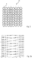
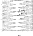
- the figure 3a allows to visualize this phenomenon.
- the figure 3a corresponds to a portion of the object space in which the optical paths of the incident beams on each pixel of the photosensitive sensor have been plotted 3.
- the points of intersections (marked by crosses) between these beams therefore correspond to the points of the object space which are imaged on at least two pixels.
- the intersections are poorly distributed in model space.
- plans (like plans -16.8 and -16.5 on the figure 3a ) in which the density of intersections is high, but there are also many planes (such as plane 16.65) in which the density of intersections is low, and large neighboring areas of these planes in which there is no intersection (like the area between planes -16.75 and -16.65 on the figure 3a ), in other words areas that are not imaged on at least two pixels. This is in particular due to the existence of many multiple intersections, which correspond to points in space which are imaged over more than two pixels.
- the figure 3b illustrates the fact that there are points whose distance to the nearest intersection is of the order of 50 micrometers.
- the resolving power of a plenoptic camera defined as the minimum distance that must separate two contiguous points for them to be imaged on pairs of different pixels, depends on the distribution of intersections in object space.
- the plenoptic cameras of the prior art therefore have good resolution in certain planes, on the other hand, they have poor overall resolution in space.
- An aim of the invention is to provide a plenoptic camera having better spatial resolution than the devices of the prior art.
- a plenoptic camera comprising an optical system which receives light coming from an object field in which is an object space intended to be processed via the camera, a matrix photosensitive sensor which is composed of pixels arranged in rows and columns and such that each pixel receives the light of a single ray of light via the optical system.
- Said camera has its optics which comprises a focusing optic and an array of optical elements which are positioned in an image plane located between the focusing optic and the photosensitive sensor.
- Each optical element forms a macropixel image on the photosensitive sensor by making its associated light ray correspond to each pixel.
- the optical elements are arranged in rows and columns parallel respectively to the rows and columns of the matrix sensor, forming the intersections in the object field,
- the distance which separates two adjacent lines of the network of optical elements and / or the distance which separates two adjacent columns of the network of optical elements is irregular in said network, this distance being distinct for at least two pairs of lines adjacent and / or two pairs of adjacent columns of the array of optical elements, the irregularity in separation distance making it possible to minimize the greatest distance between any point in object space and the closest to said intersections of these light rays.
- the distance between two adjacent lines, respectively two columns, is said to be irregular if it cannot be deduced from the knowledge of all the other distances between adjacent lines, respectively columns, or if the distance between at least twenty lines must be known, respectively twenty columns, adjacent to deduce it.
- the distance between two columns is fixed randomly, in particular by using a drawing according to a uniform law over a predetermined interval.
- the distance which separates two adjacent columns (or rows) of the array of optical elements is irregular from the moment when the difference between a value and the mean value is greater than 2% of the mean value (this condition is however not sufficient).
- the invention therefore makes it possible to improve the resolution of three-dimensional reconstruction of a plenoptic camera.
- the points of space imaged on at least two pixels are distributed more homogeneously in space, which makes it possible to have a better overall resolution in space.
- the light rays associated with their pixel form intersections in said object space and on the other hand the optics are made so as to minimize the greatest distance between any point in the object space and the closest to said intersections of these light rays.
- the invention is advantageously completed by the following characteristics, taken individually or in any of their technically possible combinations.
- the array of optical elements exhibits irregularities both as regards the distance which separates two adjacent lines of the array and as regards the distance which separates two adjacent columns.
- the fact that the array of optical elements comprises irregularities in two directions further improves the distribution of the points of space imaged over more than two pixels.
- the distance between two adjacent rows and / or two adjacent columns can for example be chosen randomly. Preferably, this distance is in a range of values between 95% and 105% of an average value. The tests carried out by the inventors made it possible to determine that this configuration allowed an increased resolution of the plenoptic camera.
- the macropixel image formed on the photosensitive sensor extends over at least two pixels in the vertical direction and / or in the horizontal direction and on the other hand the irregular distance in said network separates two adjacent lines of the network d 'optical elements in correspondence of their macropixel images of at least two pixels in the vertical direction and / or separates two adjacent columns of the array of optical elements in correspondence of their macropixel images of at least two pixels in the horizontal direction.
- Optical elements are microlenses or pinholes.
- the association between ray and pixel is dynamically chosen from a set of possible associations and makes it possible to obtain an image or more images of the object field.
- a set of controllable shutter elements positioned opposite the optical elements allows the dynamic selection of a single ray for each pixel by allowing the selection of an association from the set of possible associations, the images being formed by the optical elements on the detector and possibly having overlaps.
- a configuration of optical elements is first designed, possibly having overlaps between the macropixels, and a matrix mask is placed in front of or behind the plane of the array of optical elements.
- a matrix mask is placed in front of or behind the plane of the array of optical elements.
- the association between ray and pixels is one-to-one for at least 2 spectral bands, the associations corresponding to these spectral bands differing for at least 1 pixels.
- a set of chromatic filtering elements positioned opposite the optical elements ensures the uniqueness of the ray corresponding to each pixel in each of the spectral bands, making it possible to obtain one or more images of the object field, the images formed by the optical elements on the detector which may have overlaps.
- one passes dynamically from one configuration to another, by changing the wavelength of the lighting to make it correspond to the wavelength of the filters positioned in front of the array of optical elements corresponding to the desired configuration.
- the plenoptic camera can include two arrays of optical elements contained in the same plane, a chromatic filter allowing only wavelengths in a first frequency band to pass, being positioned in front of the optical elements. of the first network, a band-pass filter allowing only the wavelengths in a second frequency band different from the first frequency band to pass, being positioned in front of the optical elements of the second network.
- the invention also proposes a three-dimensional acquisition device, comprising a plenoptic camera as described above and a computer configured to determine, from the image supplied and / or a series of images supplied by the plenoptic camera, a distance between a point in the object field and the plenoptic camera.
- the invention also proposes the use of a three-dimensional acquisition device as described above for checking the shape and in particular for checking the shape of a turbomachine blade.
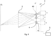
- a plenoptic camera 1 usually comprises a focusing optic 2, a photosensitive sensor 3, and an array of optical elements 40.
- An optical system comprises the focusing optic 2 and the array of optical elements 40.
- the focusing optic 2 is conventionally an optical lens or a combination of optical lenses, which receives light from objects placed in an object field.
- the plenoptic camera 1 has its optical elements 40 arranged in an image plane F 'of the plenoptic camera between the focusing optics 2 and the photosensitive sensor 3, and parallel to the sensor.
- the photosensitive sensor 3 is located at a plane referenced F "in the examples which are in the figures.
- Each optical element 4 forms on the photosensitive sensor 3 an image of the focusing optics 2.
- a point included in the plane Fc of the plane of the optical elements is imaged by a single microlens constituting a single optical element 4.
- the parameters of the camera, in particular the focal length of the focusing optics 2 and that of the microlenses 4 are chosen so that the images formed by the microlenses on the photosensitive sensor 3 do not overlap.
- the pixels receiving the light coming from the same optical element 4 form a group called a macropixel and each optical element 4 forms on the photosensitive sensor 3 a macropixel image extending over at least two pixels for said group, in the horizontal direction and / or in the vertical direction.
- the photosensitive sensor 3 is a matrix being composed of pixels arranged in rows and columns and such that each pixel receives the light of a single light ray via the optical system.
- the image taken by the photosensitive sensor 3 therefore contains sufficient information to form images seen from different points of view.
- the array of optical elements 40 is placed at a small distance (of the order of 0.5 mm) from the photosensitive sensor 3.
- the optical elements 4 can in particular be microlenses, or pinholes. In the case where the optical elements 4 are microlenses, these can be spherical or have a more complex shape allowing a junction between two adjacent microlenses 4. Microlenses typically have a diameter of the order of a fraction of a millimeter.
- the array of optical elements 40 is an opaque flat surface in which very small diameter holes are formed, typically spaced on the order of a fraction of a millimeter.
- the photosensitive sensor 3 captures the light received to produce an image.
- the photosensitive sensor 3 is a matrix sensor and typically a CCD matrix.
- the photosensitive sensor 3 is a photosensitive electronic component made up of photosites adapted to convert electromagnetic radiation (UV, visible or IR) into an analog electrical signal. This signal is then digitized by an analog-to-digital converter to obtain a digital image composed of pixels, each pixel corresponding to a photosite of the photosensitive sensor 3.
- the optical elements 4 are arranged in a coplanar manner, in a plane substantially parallel to the plane of the photosensitive sensor 3.
- the optical elements 4 are arranged so that their optical centers are aligned in rows and columns.
- the optical center of an optical element is the particular point of an optical element such that a light ray incident at this point is not deflected, its incident and emergent parts being parallel to each other.
- the optical center of the microlens is the point of intersection between the plane of the microlens and the optical axis.
- the optical center of the pinhole is the center of the hole.
- the distance between two adjacent rows is not constant, while the distance between two columns is constant, or alternatively, the distance between two adjacent rows is constant, but the distance between two columns n is not constant.
- neither the distance between two adjacent rows, nor the distance between two adjacent columns, are constant.
- the distance between two adjacent lines and that between two columns is typically less than a millimeter.
- the distance between two adjacent rows and / or that between two adjacent columns is typically chosen from a range of values between + and - 5% of an average value.
- the distance between two adjacent rows and / or that between two adjacent columns is typically chosen from a range of values between + and - 10% of an average value.
- the distance between two adjacent lines, respectively two columns, is irregular if it cannot be deduced from knowing all the other distances between adjacent lines, respectively columns, or if the distance between at least twenty lines must be known, respectively twenty columns, adjacent to deduce it.
- the distance between two adjacent rows and / or between two adjacent columns can for example be chosen randomly. This is understood to mean that in this case, the distribution of the distances between two adjacent lines and / or between two adjacent columns does not have any identifiable structure, regularity, or rule of prediction, in other words that the distance between two adjacent lines and / or between two adjacent columns is drawn at random. In fact, the tests carried out by the inventors made it possible to determine that this configuration allowed an increased three-dimensional reconstruction resolution of the plenoptic camera.
- the distance between two adjacent rows and / or that between two adjacent columns is typically chosen randomly from a range of values between + and - 5% around an average value.
- the distance between two adjacent rows and / or that between two adjacent columns is chosen randomly from a range of values between + and - 10% of an average value.
- An advantageous embodiment therefore consists in determining the distance between two columns (respectively rows) at random, in particular by using a drawing according to a uniform law over a predetermined interval of values.
- said distance is a function of a random value.
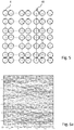
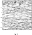
- the figure 6a corresponds to a portion of the object space in which the light rays corresponding to all the pixels have been traced.
- the points (marked by crosses) of intersections between these rays correspond to the points of model space which are imaged on at least two pixels.
- the intersections are distributed more homogeneously in space, which makes it possible to have a better overall resolution in space.
- the invention therefore makes it possible to improve the resolution of three-dimensional reconstruction of a plenoptic camera.
- the figure 6b enlargement of the figure 6a , illustrates that the point of the volume furthest from any intersection is only 12 microns from the nearest intersection.
- the three-dimensional reconstruction resolution is therefore significantly better.
- the arrangement of the optical elements 4 is advantageously modified dynamically in order to be able to adapt to particular situations.
- the arrangement of the optical elements 4 determines the positioning of the intersections, and therefore the resolution of the three-dimensional measurement in space.
- the configuration of the network of optical elements 40 will therefore be chosen as a function of the distribution of the intersections sought.
- a configuration can generate a high concentration of intersections in a particular zone of space and will be particularly interesting for acquiring an object contained in this zone of space.
- the optical system processes the light coming from the object field in which the object space is processed via the camera.
- the light rays associated with each one with their pixel form intersections in said object space and on the other hand the optics are produced so as to minimize the greatest distance between any point in the object space and the closest of said intersections of these light rays.
- Each optical element 4 forms on the photosensitive sensor 3 a macropixel image extending over at least two pixels in the vertical direction and / or in the horizontal direction by making each pixel its associated light ray.
- the optical elements 4 are aligned arranged in lines and in columns parallel respectively to the lines and columns of the matrix sensor 3, forming the intersections in the object field.
- the distance between two adjacent lines of the array of optical elements in correspondence of their macropixel images of at least two pixels in the vertical direction and / or the distance between two adjacent columns of the array of optical elements in correspondence of their images macropixels of at least two pixels in the horizontal direction is irregular in said grating. This irregularity in said distances separating said rows and / or columns makes it possible to minimize the greatest distance between any point in object space and the closest to said intersections of these light rays,
- the optical elements 4 can be moved.
- a movement of the optical elements 4 can in particular be obtained using actuators adapted to independently move each optical element 4.
- a matrix mask 50 positioned in front of or behind the array of optical elements 40, as illustrated in FIG. figure 7 , and made up of cells that can be controlled independently of each other to allow light to pass or not, for example a liquid crystal screen.
- a configuration of optical elements 4 is first designed, possibly having overlaps between the macropixels, and a matrix mask 50 is placed in front of or behind the plane of the array of optical elements 40.
- the rays coming from the optical elements 40 are dynamically modified in order to prevent more than one ray from reaching each pixel and to distribute the intersections in space.
- the set of intersections of the rays is enriched and the resolution of three-dimensional reconstruction is improved.
- the association between ray and pixel is dynamically chosen from a set of possible associations and makes it possible to obtain an image or more images of the object field.
- a set of controllable shutter elements positioned opposite the optical elements 4 so as to allow the dynamic selection of a single ray for each pixel by allowing the selection of an association in the set of 'possible associations. Since the images are formed by the optical elements 4 on the detector 3, they may have overlaps,
- Another way to dynamically change the geometry of the optical elements 4 is to position, as illustrated in the figure 8 , two arrays of optical elements 41, 42 in the same plane, and to position, in front of each optical element 4 of the first network 41 a band-pass filter 61 allowing only the wavelengths to pass in a first frequency band, and in front of each optical element 4 of the second network 42 a band-pass filter 62 allowing only the wavelengths to pass in a second frequency band different from the first frequency band.
- the networks 41 and 42 are made in such a way as to prevent more than one ray in each frequency band from reaching a pixel.
- the association between ray and pixels is one-to-one for at least 2 spectral bands, the associations corresponding to these spectral bands differing for at least 1 pixels.
- a calibration step one determines, for each point of the object field, the pixels on which the point of the object field is imaged.
- We associate with each point of the object field the pixels on which said point of the object field is imaged.
- the point in the object field must at least be imaged on two different pixels.
- the calibration can be carried out by lighting a single point of the object field at a time and by listing the pixels of the photosensitive sensor 3 illuminated, and this for a sample of points of the object space corresponding to the desired resolution.
- a screen is positioned in a plane normal to the direction of observation of the camera 1, and this screen gradually moves towards the sensor 3, in steps less than the desired distance resolution.
- each point of the screen is selectively lit in turn.
- at least the two most illuminated pixels of the sensor 3 are determined. If their level of illumination is sufficient, in practice greater than a chosen threshold, the point is associated with the pair of illuminated pixels.
- a table is thus created associating with a point of the object field the pair of pixels of the photosensitive sensor 2 on which said point is imaged.
- a three-dimensional acquisition device comprises a plenoptic camera 1, and a computer 5 configured to determine, from the image supplied or from the set of images supplied by the photosensitive sensor 3, a distance between a point of the field object and plenoptic camera 1.
- the computer 5 is configured to implement association and three-dimensional reconstruction steps as described below.
- the computer 5 associates with each other the different pixels which correspond to the same point of the object field. This is what allows the determination of the 3D coordinates of the points of the scene by triangulation.
- the different pixels which correspond to the same point of the object field are associated in a conventional manner.
- the computer 5 determines, by triangulation, the 3D coordinates of the points of the object field from the associations made and the calibration parameters of the plenoptic camera 1.
- the points visible on the images being the projections of the point of the object field, the position in space of the point of the object field is obtained by intersection of the light rays associated with the image pixels of the point of the object field.
Landscapes
- Engineering & Computer Science (AREA)
- Multimedia (AREA)
- Signal Processing (AREA)
- Physics & Mathematics (AREA)
- General Physics & Mathematics (AREA)
- Theoretical Computer Science (AREA)
- Computing Systems (AREA)
- Computer Vision & Pattern Recognition (AREA)
- Studio Devices (AREA)
Claims (14)
- Plenoptische Kamera (1), umfassend ein optisches System, das Licht empfängt, das von einem Objektfeld ausgeht, in dem ein Objektbereich bestimmt ist, über die Kamera verarbeitet zu werden, einen photoempfindlichen Matrixsensor (3), der aus Pixeln zusammengesetzt ist, die in Zeilen und Spalten angeordnet sind und derart, dass jedes Pixel das Licht von einem einzigen Lichtstrahl über das optische System empfängt, wobei:- ihr optisches System eine Fokussieroptik (2) umfasst;- ihr optisches System ein Netzwerk (40) optischer Elemente (4) umfasst, die in einer Bildebene (F') positioniert sind, die sich zwischen der Fokussieroptik (2) und dem photosensiblen Sensor (3) befindet;- jedes optische Element (4) auf dem photosensiblen Sensor (3) ein Makropixelbild bildet, indem es jedes Pixel mit seinem zugeordneten Lichtstrahl in Übereinstimmung bringt;- und wobei die optischen Elemente eine unregelmäßige Struktur habenund dadurch gekennzeichnet, dass:- die optischen Elemente (4) in Zeilen und in Spalten angeordnet sind, die jeweils zu den Linien und Spalten des Matrixsensors (3) parallel sind, indem sie die Schnittpunkte im Objektfeld bilden;- der Abstand, der zwei benachbarte Zeilen des Netzwerks optischer Elemente trennt und/oder der Abstand, der zwei benachbarte Spalten des Netzwerks optischer Elemente trennt, in dem Netzwerk unregelmäßig ist, wobei sich dieser Abstand für mindestens zwei Paare benachbarter Zeilen und/oder zwei Paare benachbarter Spalten des Netzwerks optischer Elemente unterscheidet.
- Plenoptische Kamera (1) nach vorangehendem Anspruch, wobei das Netzwerk optischer Elemente sowohl im Hinblick auf den Abstand, der zwei benachbarte Zeilen des Netzwerks trennt, und im Hinblick auf den Abstand, der zwei benachbarte Spalten trennt, Unregelmäßigkeiten aufweist.
- Plenoptische Kamera nach einem der vorangehenden Ansprüche, wobei der Abstand zwischen zwei benachbarten Spalten beziehungsweise Zeilen von einem Zufallswert abhängt, vorzugsweise mit Hilfe einer Ziehung eines Zufallswerts gemäß einem einheitlichen Gesetz über ein vorbestimmtes Werteintervall.
- Plenoptische Kamera (1) nach einem der Ansprüche 1 bis 3, wobei zum einen sich das auf dem photosensiblen Sensor (3) gebildete Makropixelbild über mindestens zwei Pixel in der vertikalen Richtung und/oder in der horizontalen Richtung erstreckt und zum anderen der unregelmäßige Abstand im Netzwerk zwei benachbarte Zeilen des Netzwerks optischer Elemente übereinstimmend mit ihren Makropixelbildern um mindestens zwei Pixel in der vertikalen Richtung trennt und/oder zwei benachbarte Spalten des Netzwerks optischer Elemente übereinstimmend mit ihren Makropixelbildern um mindestens zwei Pixel in der horizontalen Richtung trennt.
- Plenoptische Kamera (1) nach einem der Ansprüche 1 bis 4, wobei der Abstand zwischen zwei benachbarten Zeilen und/oder zwei benachbarten Spalten zufällig gewählt ist.
- Plenoptische Kamera (1) nach einem der Ansprüche 1 bis 5, wobei der Abstand zwischen zwei benachbarten Zeilen und/oder zwei benachbarten Spalten aus einem Wertebereich zwischen 95% und 105% eines Mittelwerts zufällig gewählt ist.
- Plenoptische Kamera (1) nach einem der Ansprüche 1 bis 6, wobei die optischen Elemente (4) Mikrolinsen sind.
- Plenoptische Kamera (1) nach einem der Ansprüche 1 bis 6, wobei die optischen Elemente (4) Lochblenden sind.
- Plenoptische Kamera (1) nach Anspruch 1, wobei die Zuordnung zwischen Strahl und Pixel dynamisch aus einer Gruppe möglicher Zuordnungen gewählt ist und erlaubt, ein Bild oder mehrere Bilder des Objektfelds zu erhalten.
- Plenoptische Kamera (1) nach Anspruch 9, wobei eine Gruppe lenkbarer Verschlusselemente, die den optischen Elementen (4) zugewandt positioniert ist, die dynamische Auswahl eines einzigen Strahls für jedes Pixel durch Gestattung der Auswahl einer Zuordnung aus der Gruppe möglicher Zuordnungen erlaubt, wobei die Bilder von den optischen Elementen (4) auf dem Detektor (3) gebildet werden und Überlappungen aufweisen können.
- Plenoptische Kamera (1) nach Anspruch 1, wobei die Zuordnung zwischen Strahl und Pixeln für mindestens 2 Spektralbänder eins zu eins ist, wobei die Zuordnungen, die diesen Spektralbändern entsprechen, für mindestens 1 Pixel unterschiedlich sind.
- Plenoptische Kamera (1) nach Anspruch 11 und einem der vorangehenden Ansprüche, wobei eine Gruppe chromatischer Filterungselemente, die den optischen Elementen (4) zugewandt positioniert ist, die Eindeutigkeit des Strahls sichert, der jedem Pixel in jedem der Spektralbänder entspricht, was gestattet, ein Bild oder mehrere Bilder des Objektfelds zu erhalten, wobei die von den optischen Elementen (4) auf dem Detektor (3) gebildeten Bilder Überlappungen aufweisen können.
- Dreidimensionale Aufnahmevorrichtung, aufweisend eine plenoptische Kamera (1) nach einem der vorangehenden Ansprüche und einen Rechner (5), der ausgelegt ist, um ausgehend von dem bereitgestellten Bild und/oder von einer Reihe von der plenoptischen Kamera (1) bereitgestellter Bilder einen Abstand zwischen einem Punkt des Objektfelds und der plenoptischen Kamera (1) zu bestimmen.
- Verfahren zum Kalibrieren einer plenoptischen Kamera (1) nach einem der Ansprüche 1 bis 12, aufweisend die folgenden Schritte:- Einschalten eines einzigen Punkts des Objektfelds;- Identifizieren der beleuchteten Pixel des photosensiblen Sensors (3);- Zuordnen der beleuchteten Pixel des photosensiblen Sensors (3) zum Punkt des Objektfelds;- Wiederholen der vorangehenden Schritte für eine Probe von Punkten des Objektfelds.
Applications Claiming Priority (2)
| Application Number | Priority Date | Filing Date | Title |
|---|---|---|---|
| FR1558338A FR3040798B1 (fr) | 2015-09-08 | 2015-09-08 | Camera plenoptique |
| PCT/FR2016/052242 WO2017042494A1 (fr) | 2015-09-08 | 2016-09-08 | Caméra plénoptique |
Publications (2)
| Publication Number | Publication Date |
|---|---|
| EP3348048A1 EP3348048A1 (de) | 2018-07-18 |
| EP3348048B1 true EP3348048B1 (de) | 2020-10-28 |
Family
ID=54329816
Family Applications (1)
| Application Number | Title | Priority Date | Filing Date |
|---|---|---|---|
| EP16785184.9A Active EP3348048B1 (de) | 2015-09-08 | 2016-09-08 | Plenoptische kamera |
Country Status (4)
| Country | Link |
|---|---|
| US (1) | US10778874B2 (de) |
| EP (1) | EP3348048B1 (de) |
| FR (1) | FR3040798B1 (de) |
| WO (1) | WO2017042494A1 (de) |
Families Citing this family (6)
| Publication number | Priority date | Publication date | Assignee | Title |
|---|---|---|---|---|
| FR3051584B1 (fr) | 2016-05-20 | 2019-11-01 | Safran | Procede de reconstruction tridimensionnelle a l'aide d'une camera plenoptique. |
| CN107767440B (zh) * | 2017-09-06 | 2021-01-26 | 北京建筑大学 | 基于三角网内插及约束的文物序列影像精细三维重建方法 |
| FR3115626B1 (fr) | 2020-10-26 | 2025-02-14 | Safran | Procédé de calibrage d’une caméra plénoptique |
| US12125242B2 (en) | 2022-01-06 | 2024-10-22 | Liberty Robotics Inc. | Method and system for registering a 3D sensor with an autonomous manipulator |
| CN114167622A (zh) * | 2021-12-14 | 2022-03-11 | 樊宸 | 一种用于获取被拍摄物表面三维信息的光学系统 |
| FR3132968B1 (fr) | 2022-02-22 | 2024-12-20 | Safran | Procédé de calibrage d’une caméra plénoptique |
Family Cites Families (12)
| Publication number | Priority date | Publication date | Assignee | Title |
|---|---|---|---|---|
| US20060192869A1 (en) * | 2005-02-28 | 2006-08-31 | Kazutora Yoshino | Multi-dimensional input, transfer, optional memory, and output method |
| US7671321B2 (en) | 2005-01-18 | 2010-03-02 | Rearden, Llc | Apparatus and method for capturing still images and video using coded lens imaging techniques |
| EP2244484B1 (de) * | 2009-04-22 | 2012-03-28 | Raytrix GmbH | Digitales Bildgebungsverfahren zum Synthetisieren eines Bildes unter Verwendung der mit einer plenoptischen Kamera aufgezeichneten Daten |
| KR101300733B1 (ko) * | 2012-01-12 | 2013-08-27 | 연세대학교 산학협력단 | 다중 병렬 공초점 시스템 |
| JP5963448B2 (ja) * | 2012-01-13 | 2016-08-03 | キヤノン株式会社 | 撮像装置 |
| JP5836821B2 (ja) * | 2012-01-30 | 2015-12-24 | オリンパス株式会社 | 撮像装置 |
| GB2501936B (en) * | 2012-05-11 | 2016-11-30 | Canon Kk | Micro lens array and imaging apparatus |
| JP2015060121A (ja) * | 2013-09-19 | 2015-03-30 | 株式会社東芝 | カラーフィルタアレイおよび固体撮像素子 |
| JP6417809B2 (ja) * | 2014-03-05 | 2018-11-07 | ソニー株式会社 | 撮像装置 |
| US9544583B2 (en) * | 2015-01-09 | 2017-01-10 | Ricoh Company, Ltd. | Object space calibration of plenoptic imaging systems |
| FR3051584B1 (fr) * | 2016-05-20 | 2019-11-01 | Safran | Procede de reconstruction tridimensionnelle a l'aide d'une camera plenoptique. |
| EP3494543B1 (de) * | 2016-08-05 | 2023-06-28 | InterDigital CE Patent Holdings | Verfahren zum erhalten von mindestens einem subaperturbild, das einer ansicht zugeordnet ist |
-
2015
- 2015-09-08 FR FR1558338A patent/FR3040798B1/fr not_active Expired - Fee Related
-
2016
- 2016-09-08 WO PCT/FR2016/052242 patent/WO2017042494A1/fr not_active Ceased
- 2016-09-08 US US15/758,111 patent/US10778874B2/en active Active
- 2016-09-08 EP EP16785184.9A patent/EP3348048B1/de active Active
Non-Patent Citations (1)
| Title |
|---|
| None * |
Also Published As
| Publication number | Publication date |
|---|---|
| FR3040798A1 (fr) | 2017-03-10 |
| US20180249050A1 (en) | 2018-08-30 |
| WO2017042494A1 (fr) | 2017-03-16 |
| US10778874B2 (en) | 2020-09-15 |
| EP3348048A1 (de) | 2018-07-18 |
| FR3040798B1 (fr) | 2018-02-09 |
Similar Documents
| Publication | Publication Date | Title |
|---|---|---|
| WO2017042494A1 (fr) | Caméra plénoptique | |
| CA2072341C (fr) | Procede de mesure de luminance et appareil pour la mise en oeuvre de ce procede | |
| FR3065132B1 (fr) | Dispositif et procede d'imagerie multispectrale dans l'infrarouge | |
| EP3459051B1 (de) | Dreidimensionales rekonstruktionsverfahren unter verwendung einer plenoptischen kamera | |
| FR2969819A1 (fr) | Capteur d'image tridimensionnel | |
| FR3007534A1 (fr) | Realisation d'un filtre spectral nanostructure | |
| EP2681604B1 (de) | Hochauflösendes bildgebungssystem | |
| EP3458819A1 (de) | Mehrkanaliger fourier-transformationsspektralbildaufnehmer | |
| EP2846357A1 (de) | Fotodetektorvorrichtung mit Halbleiterregionen, die durch eine Potenzialbarriere getrennt sind | |
| FR2755337A1 (fr) | Systeme de camera | |
| FR3107124A1 (fr) | Appareil pour l’observation d’un astre | |
| FR3026227A1 (fr) | Dispositif d'acquisition d'images 3d | |
| EP3688808B1 (de) | Neudimensionierung von detektionseinheiten eines hybriden matrixbildsensors | |
| FR3102845A1 (fr) | Détermination d'au moins un paramètre optique d'une lentille optique | |
| WO2022129721A1 (fr) | Procede d'inspection d'une surface d'un objet | |
| WO2021019136A1 (fr) | Dispositif d'inspection d'une surface d'un objet | |
| EP3516353B1 (de) | Verfahren zur verbesserung der detektion von kapazitäten eines multispektralen bildgebungssystems | |
| FR3041458A1 (fr) | Dispositif d'imagerie, vehicule automobile equipe d'un tel dispositif d'imagerie, et procede associe | |
| EP2093602A1 (de) | Bildgebungsvorrichtung mit mehreren Strahlablenkern | |
| WO2017120640A1 (en) | Image sensor | |
| EP4553464A1 (de) | Polarimetrische kamera | |
| FR2690533A1 (fr) | Capteur de type appareil de prise de vue. | |
| EP3165875B1 (de) | Verfahren zur bilderfassung mithilfe eines optischen instruments für die raumfahrt oder an bord eines luftfahrzeugs mit erweitertem sichtfeld | |
| FR2860119A1 (fr) | Dispositif et procede pour produire la representation d'une scene objet | |
| FR2960065A1 (fr) | Dispositif combine d'observation et d'emission, et procede de visualisation d'une direction d'emission d'un tel dispositif |
Legal Events
| Date | Code | Title | Description |
|---|---|---|---|
| STAA | Information on the status of an ep patent application or granted ep patent |
Free format text: STATUS: UNKNOWN |
|
| STAA | Information on the status of an ep patent application or granted ep patent |
Free format text: STATUS: THE INTERNATIONAL PUBLICATION HAS BEEN MADE |
|
| PUAI | Public reference made under article 153(3) epc to a published international application that has entered the european phase |
Free format text: ORIGINAL CODE: 0009012 |
|
| STAA | Information on the status of an ep patent application or granted ep patent |
Free format text: STATUS: REQUEST FOR EXAMINATION WAS MADE |
|
| 17P | Request for examination filed |
Effective date: 20180330 |
|
| AK | Designated contracting states |
Kind code of ref document: A1 Designated state(s): AL AT BE BG CH CY CZ DE DK EE ES FI FR GB GR HR HU IE IS IT LI LT LU LV MC MK MT NL NO PL PT RO RS SE SI SK SM TR |
|
| AX | Request for extension of the european patent |
Extension state: BA ME |
|
| DAV | Request for validation of the european patent (deleted) | ||
| DAX | Request for extension of the european patent (deleted) | ||
| REG | Reference to a national code |
Ref country code: DE Ref legal event code: R079 Ref document number: 602016046774 Country of ref document: DE Free format text: PREVIOUS MAIN CLASS: H04N0005225000 Ipc: H04N0013232000 |
|
| RIC1 | Information provided on ipc code assigned before grant |
Ipc: H04N 5/225 20060101ALI20200330BHEP Ipc: H04N 13/232 20180101AFI20200330BHEP Ipc: G03B 35/08 20060101ALI20200330BHEP |
|
| GRAP | Despatch of communication of intention to grant a patent |
Free format text: ORIGINAL CODE: EPIDOSNIGR1 |
|
| STAA | Information on the status of an ep patent application or granted ep patent |
Free format text: STATUS: GRANT OF PATENT IS INTENDED |
|
| INTG | Intention to grant announced |
Effective date: 20200511 |
|
| RIN1 | Information on inventor provided before grant (corrected) |
Inventor name: LE GUILLOUX, YANN Inventor name: PICARD, SYLVAINE |
|
| GRAS | Grant fee paid |
Free format text: ORIGINAL CODE: EPIDOSNIGR3 |
|
| GRAA | (expected) grant |
Free format text: ORIGINAL CODE: 0009210 |
|
| STAA | Information on the status of an ep patent application or granted ep patent |
Free format text: STATUS: THE PATENT HAS BEEN GRANTED |
|
| AK | Designated contracting states |
Kind code of ref document: B1 Designated state(s): AL AT BE BG CH CY CZ DE DK EE ES FI FR GB GR HR HU IE IS IT LI LT LU LV MC MK MT NL NO PL PT RO RS SE SI SK SM TR |
|
| REG | Reference to a national code |
Ref country code: GB Ref legal event code: FG4D Free format text: NOT ENGLISH |
|
| REG | Reference to a national code |
Ref country code: CH Ref legal event code: EP |
|
| REG | Reference to a national code |
Ref country code: AT Ref legal event code: REF Ref document number: 1329438 Country of ref document: AT Kind code of ref document: T Effective date: 20201115 |
|
| REG | Reference to a national code |
Ref country code: DE Ref legal event code: R096 Ref document number: 602016046774 Country of ref document: DE |
|
| REG | Reference to a national code |
Ref country code: IE Ref legal event code: FG4D Free format text: LANGUAGE OF EP DOCUMENT: FRENCH |
|
| REG | Reference to a national code |
Ref country code: AT Ref legal event code: MK05 Ref document number: 1329438 Country of ref document: AT Kind code of ref document: T Effective date: 20201028 |
|
| REG | Reference to a national code |
Ref country code: NL Ref legal event code: MP Effective date: 20201028 |
|
| PG25 | Lapsed in a contracting state [announced via postgrant information from national office to epo] |
Ref country code: NO Free format text: LAPSE BECAUSE OF FAILURE TO SUBMIT A TRANSLATION OF THE DESCRIPTION OR TO PAY THE FEE WITHIN THE PRESCRIBED TIME-LIMIT Effective date: 20210128 Ref country code: RS Free format text: LAPSE BECAUSE OF FAILURE TO SUBMIT A TRANSLATION OF THE DESCRIPTION OR TO PAY THE FEE WITHIN THE PRESCRIBED TIME-LIMIT Effective date: 20201028 Ref country code: PT Free format text: LAPSE BECAUSE OF FAILURE TO SUBMIT A TRANSLATION OF THE DESCRIPTION OR TO PAY THE FEE WITHIN THE PRESCRIBED TIME-LIMIT Effective date: 20210301 Ref country code: GR Free format text: LAPSE BECAUSE OF FAILURE TO SUBMIT A TRANSLATION OF THE DESCRIPTION OR TO PAY THE FEE WITHIN THE PRESCRIBED TIME-LIMIT Effective date: 20210129 Ref country code: FI Free format text: LAPSE BECAUSE OF FAILURE TO SUBMIT A TRANSLATION OF THE DESCRIPTION OR TO PAY THE FEE WITHIN THE PRESCRIBED TIME-LIMIT Effective date: 20201028 |
|
| REG | Reference to a national code |
Ref country code: LT Ref legal event code: MG4D |
|
| PG25 | Lapsed in a contracting state [announced via postgrant information from national office to epo] |
Ref country code: SE Free format text: LAPSE BECAUSE OF FAILURE TO SUBMIT A TRANSLATION OF THE DESCRIPTION OR TO PAY THE FEE WITHIN THE PRESCRIBED TIME-LIMIT Effective date: 20201028 Ref country code: ES Free format text: LAPSE BECAUSE OF FAILURE TO SUBMIT A TRANSLATION OF THE DESCRIPTION OR TO PAY THE FEE WITHIN THE PRESCRIBED TIME-LIMIT Effective date: 20201028 Ref country code: AT Free format text: LAPSE BECAUSE OF FAILURE TO SUBMIT A TRANSLATION OF THE DESCRIPTION OR TO PAY THE FEE WITHIN THE PRESCRIBED TIME-LIMIT Effective date: 20201028 Ref country code: BG Free format text: LAPSE BECAUSE OF FAILURE TO SUBMIT A TRANSLATION OF THE DESCRIPTION OR TO PAY THE FEE WITHIN THE PRESCRIBED TIME-LIMIT Effective date: 20210128 Ref country code: PL Free format text: LAPSE BECAUSE OF FAILURE TO SUBMIT A TRANSLATION OF THE DESCRIPTION OR TO PAY THE FEE WITHIN THE PRESCRIBED TIME-LIMIT Effective date: 20201028 Ref country code: IS Free format text: LAPSE BECAUSE OF FAILURE TO SUBMIT A TRANSLATION OF THE DESCRIPTION OR TO PAY THE FEE WITHIN THE PRESCRIBED TIME-LIMIT Effective date: 20210228 Ref country code: LV Free format text: LAPSE BECAUSE OF FAILURE TO SUBMIT A TRANSLATION OF THE DESCRIPTION OR TO PAY THE FEE WITHIN THE PRESCRIBED TIME-LIMIT Effective date: 20201028 |
|
| PG25 | Lapsed in a contracting state [announced via postgrant information from national office to epo] |
Ref country code: NL Free format text: LAPSE BECAUSE OF FAILURE TO SUBMIT A TRANSLATION OF THE DESCRIPTION OR TO PAY THE FEE WITHIN THE PRESCRIBED TIME-LIMIT Effective date: 20201028 Ref country code: HR Free format text: LAPSE BECAUSE OF FAILURE TO SUBMIT A TRANSLATION OF THE DESCRIPTION OR TO PAY THE FEE WITHIN THE PRESCRIBED TIME-LIMIT Effective date: 20201028 |
|
| REG | Reference to a national code |
Ref country code: DE Ref legal event code: R097 Ref document number: 602016046774 Country of ref document: DE |
|
| PG25 | Lapsed in a contracting state [announced via postgrant information from national office to epo] |
Ref country code: LT Free format text: LAPSE BECAUSE OF FAILURE TO SUBMIT A TRANSLATION OF THE DESCRIPTION OR TO PAY THE FEE WITHIN THE PRESCRIBED TIME-LIMIT Effective date: 20201028 Ref country code: SM Free format text: LAPSE BECAUSE OF FAILURE TO SUBMIT A TRANSLATION OF THE DESCRIPTION OR TO PAY THE FEE WITHIN THE PRESCRIBED TIME-LIMIT Effective date: 20201028 Ref country code: CZ Free format text: LAPSE BECAUSE OF FAILURE TO SUBMIT A TRANSLATION OF THE DESCRIPTION OR TO PAY THE FEE WITHIN THE PRESCRIBED TIME-LIMIT Effective date: 20201028 Ref country code: EE Free format text: LAPSE BECAUSE OF FAILURE TO SUBMIT A TRANSLATION OF THE DESCRIPTION OR TO PAY THE FEE WITHIN THE PRESCRIBED TIME-LIMIT Effective date: 20201028 Ref country code: SK Free format text: LAPSE BECAUSE OF FAILURE TO SUBMIT A TRANSLATION OF THE DESCRIPTION OR TO PAY THE FEE WITHIN THE PRESCRIBED TIME-LIMIT Effective date: 20201028 Ref country code: RO Free format text: LAPSE BECAUSE OF FAILURE TO SUBMIT A TRANSLATION OF THE DESCRIPTION OR TO PAY THE FEE WITHIN THE PRESCRIBED TIME-LIMIT Effective date: 20201028 |
|
| PG25 | Lapsed in a contracting state [announced via postgrant information from national office to epo] |
Ref country code: DK Free format text: LAPSE BECAUSE OF FAILURE TO SUBMIT A TRANSLATION OF THE DESCRIPTION OR TO PAY THE FEE WITHIN THE PRESCRIBED TIME-LIMIT Effective date: 20201028 |
|
| PLBE | No opposition filed within time limit |
Free format text: ORIGINAL CODE: 0009261 |
|
| STAA | Information on the status of an ep patent application or granted ep patent |
Free format text: STATUS: NO OPPOSITION FILED WITHIN TIME LIMIT |
|
| 26N | No opposition filed |
Effective date: 20210729 |
|
| PG25 | Lapsed in a contracting state [announced via postgrant information from national office to epo] |
Ref country code: AL Free format text: LAPSE BECAUSE OF FAILURE TO SUBMIT A TRANSLATION OF THE DESCRIPTION OR TO PAY THE FEE WITHIN THE PRESCRIBED TIME-LIMIT Effective date: 20201028 Ref country code: IT Free format text: LAPSE BECAUSE OF FAILURE TO SUBMIT A TRANSLATION OF THE DESCRIPTION OR TO PAY THE FEE WITHIN THE PRESCRIBED TIME-LIMIT Effective date: 20201028 |
|
| PG25 | Lapsed in a contracting state [announced via postgrant information from national office to epo] |
Ref country code: SI Free format text: LAPSE BECAUSE OF FAILURE TO SUBMIT A TRANSLATION OF THE DESCRIPTION OR TO PAY THE FEE WITHIN THE PRESCRIBED TIME-LIMIT Effective date: 20201028 |
|
| REG | Reference to a national code |
Ref country code: CH Ref legal event code: PL |
|
| REG | Reference to a national code |
Ref country code: BE Ref legal event code: MM Effective date: 20210930 |
|
| PG25 | Lapsed in a contracting state [announced via postgrant information from national office to epo] |
Ref country code: IS Free format text: LAPSE BECAUSE OF FAILURE TO SUBMIT A TRANSLATION OF THE DESCRIPTION OR TO PAY THE FEE WITHIN THE PRESCRIBED TIME-LIMIT Effective date: 20210228 Ref country code: MC Free format text: LAPSE BECAUSE OF FAILURE TO SUBMIT A TRANSLATION OF THE DESCRIPTION OR TO PAY THE FEE WITHIN THE PRESCRIBED TIME-LIMIT Effective date: 20201028 |
|
| PG25 | Lapsed in a contracting state [announced via postgrant information from national office to epo] |
Ref country code: LU Free format text: LAPSE BECAUSE OF NON-PAYMENT OF DUE FEES Effective date: 20210908 Ref country code: IE Free format text: LAPSE BECAUSE OF NON-PAYMENT OF DUE FEES Effective date: 20210908 Ref country code: BE Free format text: LAPSE BECAUSE OF NON-PAYMENT OF DUE FEES Effective date: 20210930 |
|
| PG25 | Lapsed in a contracting state [announced via postgrant information from national office to epo] |
Ref country code: LI Free format text: LAPSE BECAUSE OF NON-PAYMENT OF DUE FEES Effective date: 20210930 Ref country code: CH Free format text: LAPSE BECAUSE OF NON-PAYMENT OF DUE FEES Effective date: 20210930 |
|
| PG25 | Lapsed in a contracting state [announced via postgrant information from national office to epo] |
Ref country code: HU Free format text: LAPSE BECAUSE OF FAILURE TO SUBMIT A TRANSLATION OF THE DESCRIPTION OR TO PAY THE FEE WITHIN THE PRESCRIBED TIME-LIMIT; INVALID AB INITIO Effective date: 20160908 |
|
| PG25 | Lapsed in a contracting state [announced via postgrant information from national office to epo] |
Ref country code: CY Free format text: LAPSE BECAUSE OF FAILURE TO SUBMIT A TRANSLATION OF THE DESCRIPTION OR TO PAY THE FEE WITHIN THE PRESCRIBED TIME-LIMIT Effective date: 20201028 |
|
| PG25 | Lapsed in a contracting state [announced via postgrant information from national office to epo] |
Ref country code: MK Free format text: LAPSE BECAUSE OF FAILURE TO SUBMIT A TRANSLATION OF THE DESCRIPTION OR TO PAY THE FEE WITHIN THE PRESCRIBED TIME-LIMIT Effective date: 20201028 |
|
| PG25 | Lapsed in a contracting state [announced via postgrant information from national office to epo] |
Ref country code: MT Free format text: LAPSE BECAUSE OF FAILURE TO SUBMIT A TRANSLATION OF THE DESCRIPTION OR TO PAY THE FEE WITHIN THE PRESCRIBED TIME-LIMIT Effective date: 20201028 |
|
| PGFP | Annual fee paid to national office [announced via postgrant information from national office to epo] |
Ref country code: DE Payment date: 20250919 Year of fee payment: 10 |
|
| PGFP | Annual fee paid to national office [announced via postgrant information from national office to epo] |
Ref country code: GB Payment date: 20250923 Year of fee payment: 10 |
|
| PGFP | Annual fee paid to national office [announced via postgrant information from national office to epo] |
Ref country code: FR Payment date: 20250923 Year of fee payment: 10 |
|
| PG25 | Lapsed in a contracting state [announced via postgrant information from national office to epo] |
Ref country code: TR Free format text: LAPSE BECAUSE OF FAILURE TO SUBMIT A TRANSLATION OF THE DESCRIPTION OR TO PAY THE FEE WITHIN THE PRESCRIBED TIME-LIMIT Effective date: 20201028 |