EP3348145A1 - Procédé, emporte-pièce et système de fabrication d'en-cas à base de pâte - Google Patents
Procédé, emporte-pièce et système de fabrication d'en-cas à base de pâte Download PDFInfo
- Publication number
- EP3348145A1 EP3348145A1 EP17151355.9A EP17151355A EP3348145A1 EP 3348145 A1 EP3348145 A1 EP 3348145A1 EP 17151355 A EP17151355 A EP 17151355A EP 3348145 A1 EP3348145 A1 EP 3348145A1
- Authority
- EP
- European Patent Office
- Prior art keywords
- dough
- roller
- piercing
- wall
- treadmill
- Prior art date
- Legal status (The legal status is an assumption and is not a legal conclusion. Google has not performed a legal analysis and makes no representation as to the accuracy of the status listed.)
- Granted
Links
Images

Classifications
-
- A—HUMAN NECESSITIES
- A21—BAKING; EDIBLE DOUGHS
- A21C—MACHINES OR EQUIPMENT FOR MAKING OR PROCESSING DOUGHS; HANDLING BAKED ARTICLES MADE FROM DOUGH
- A21C11/00—Other machines for forming the dough into its final shape before cooking or baking
- A21C11/02—Embossing machines
- A21C11/04—Embossing machines with cutting and embossing rollers or drums
-
- A—HUMAN NECESSITIES
- A21—BAKING; EDIBLE DOUGHS
- A21C—MACHINES OR EQUIPMENT FOR MAKING OR PROCESSING DOUGHS; HANDLING BAKED ARTICLES MADE FROM DOUGH
- A21C11/00—Other machines for forming the dough into its final shape before cooking or baking
- A21C11/10—Other machines for forming the dough into its final shape before cooking or baking combined with cutting apparatus
Definitions
- the present invention is to provide a new manufacturing method for stacked chips and similar snack products that enables economical recycling of raw materials and novel design approaches.
- a method of forming baked dough products or stacked chips of at least one raw material with punched out openings comprises providing a dough sheet on a conveyor or treadmill.
- the dough is produced essentially in a conventional manner.
- a dough sheet is made of a raw material powder, e.g. Mashed potatoes or mashed potato powder and applied to the treadmill, preferably the treadmill passes under appropriately set rollers, so that the resulting dough sheet can be further processed directly.
- the dough sheet is then further processed in a two-stage Ausstechvon.
- the dough sheet is first transported by means of the treadmill to a first cutter.
- the first cut-out device protrudes dough openings in the dough sheet, wherein the punched-out dough is preferably transported away from the dough sheet by means of the first cut-out device.
- the punched dough as described below, can be transported into the interior of the first cut-out device and be transported away from there by means of a screw rotatable relative to the cut-out device and recycled.
- other mechanisms are conceivable, e.g. an ejection mechanism on a slide or a transporting treadmill.
- a cut-out device which furthermore preferably functions as a first cut-out device in the above method.
- the piercing device for forming stacked chips comprises a roller having an outer cylindrical carrier surface, the roller having a multiplicity of openings in the region of the carrier surface.
- On the roller is a variety of provided or fastened closed Ausstechschreibn.
- the Ausstechpara extend away from the support surface of the roller to the outside.
- Each Ausstechwand surrounds each an inner region which communicates with at least one of the opening in the support surface.
- the Ausstechvortechnische is preferably equipped with Ausstechpasn, each having a vertical cross section, which includes a Ausstechwandinnenseite and a Ausstechwandau onseite.
- the one Ausstechwandinnenseite faces the surrounded by the Ausstechwand inner region and extends substantially radially to the roll axis to the outside.
- the Ausstechwandau technology is facing away from the inner wall surrounded by the Ausstechwand and inclined with respect to the Ausstechwandinnenseite so that the Ausstechwandinnenseite and the Ausstechwandau outside with respect to the roll axis outboard meet.
- the area where the cookie cutter inside and the cookie cutter outside meet is the area that, in use, contacts the treadmill with the area thereon to knock out portions of the dough web, and will be referred to herein as a cookout edge.
- the inclination between Ausstechwandinnenseite and Ausstechwandau onseite is chosen so that an angle of 30 ° to 65 °, preferably 40 ° to 60 °, more preferably 45 ° to 55 ° between them is included.
- a projection extends from the Ausstechrand substantially perpendicular to Ausstechwandinnenseite in the direction of the enclosed inner region. By the projection, the backflow of the punched out dough is inhibited.
- the dough openings are gouged out through the cutout wall, wherein the punched dough is transported through the openings in the carrier surface into the interior of the roll, and wherein the protrusion of the cutout wall forms the punched out dough in the Keeps inside area and prevents the dough from flowing out of the interior again.
- the present invention also provides a system for forming a stacked dough product.
- the system comprises a treadmill suitable for receiving a dough sheet, a first piercing device as described above, wherein the roller is rotatable and supported such that the radially outward cutout portion of the piercer engages the treadmill and a second piercer engages a second one Roller arranged with respect to the running direction of the treadmill after the first roller and adapted to punch out an outline of a stacked chip blank.
- the system for forming a stacked chip further comprises a movable cooking support having a plurality of cylindrically curved surfaces each having a plurality of holes and adapted to continuously eject the dough pieces with the outline of a stacked chip blank punched out by the cutter and the second roller accommodate cylindrical curved surface.
- the system further comprises a fryer, wherein the cooking support is adapted to immerse in the deep fryer, so that the skilletokenen dough pieces are baked on the Garhalterung, the Garhalterung are particularly preferably arranged in the fryer.
- the present invention also provides the use of a piercing apparatus as described above in a method as described above.
- the present invention also provides a stacked die having punched out inner parts and adapted outer shape made by a method as described above.
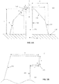
- FIG. 1A is a schematic representation of a vertical cross section through a Ausstechwand 220 a Ausstechvorraum 200 according to an embodiment of the present invention
- Fig. 1B is an enlarged schematic representation of the Area Z in Fig. 1A
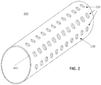
- FIG. 10 is a schematic perspective view of a cutter 200 according to one embodiment of the present invention.
- FIG. Fig. 3 FIG. 12 is a schematic representation of a radial cross section through a cutter 200 according to one embodiment of the present invention.
- the Ausstechdon 220 may be arranged in a row on a support surface 230 of the cutter 200.
- the present invention is not limited to a particular arrangement of Ausstechdon 220 and other arrangement patterns, such as grid-shaped or offset laterally, are also conceivable.
- the inner regions and the openings have a similar opening ratio (ie area of the opening cross-section) to a to allow even flow of dough.
- the orifice has a smaller, preferably 10% -50% lower, orifice ratio to inhibit backflow of the dough from the interior of the roll (not shown).
- the opening 232 preferably has an opening ratio or a diameter which corresponds to that of the cross section of the inner area (see FIG Fig. 1A ).
- a vertical cross section of each of the Ausstechdon 220 includes a Ausstechwandinnenseite 224, which faces the surrounded by the Ausstechwand 220 inner region 222 and substantially radially to the cylinder axis of the roll or the roll axis W1 (Fig. Fig. 2 and 3 ) extends to the outside.
- the support surface 230 is shown as being planar or "rolled out" even if the support surface 230 actually corresponds to the lateral surface of a cylinder.
- each of the Ausstechtown 220 also includes a Austechwandau onseite 226 facing away from the Ausstechwand 220 inner region 222 and is inclined with respect to the Ausstechwandinnenseite 224 so that the Ausstechwandinnenseite 224 and the Ausstechwandau onseite 226 with respect to the roll axis W1 outboard meet to a To form Ausstechrand.
- the area where the cookie cutter inner side 224 and the cookie cutter outside 226 meet is preferably flattened to prevent breakage or bending of the cook bar and sticking of the dough.
- the Ausstechwandinnenseite 224 and the Ausstechwandau onseite 226 include an angle A of 30 ° to 65 °, preferably 40 ° to 60 °, more preferably 45 ° to 55 °.
- a projection 228 is provided which in Fig. 1B is shown enlarged.
- the projection 228 extends from the Ausstechrand the Ausstechwand 220 substantially perpendicular to the Ausstechwandinnenseite 224 in the direction of the enclosed inner region 222. That is, the projection 228 is approximately parallel to the support surface 230 in the region of the respective Ausstechwand 222.
- the cutout wall 220 extends 1.5mm - 4mm, preferably 2.5mm - 3.5mm away from the support surface 230 (dimension c). That is, this distance is between the support surface 230 of the roller and the outermost Ausstechrand.
- the width of the cutout wall in the area where the cutout wall support side 227 (as in FIG Fig. 1A shown) on the support surface 230 meets (dimension d) is about 1.5mm - 3mm, preferably 1.8mm - 2.5mm.
- the width of the cutout wall in the area where the cookie cutter outside 226 meets the cookout wall mounting side 227 is about 1.0mm - 2.5mm, preferably 1.3mm - 2.0mm.
- the width of the Ausstechands including the projection 228 is about 0.2mm - 0.8mm, preferably 0.4mm - 0.6mm. Accordingly, the width of the Ausstechands without the projection 228 is about 0.1mm - 0.7mm, preferably 0.3mm - 0.5mm.
- the height of the projection is about 0.05 mm - 0.2 mm, preferably 0.08 mm - 0.15 mm and the width of the projection (dimension e) is also about 0.05 mm - 0.2 mm, preferably 0.08 mm - 0.15mm.
- the cutout wall is preferably solid for stability, and may also have voids in some embodiments.
- the projection 228 is preferably in one piece formed with the Ausstechwand 220 and consists essentially of the same material as the Ausstechwand 220. Preferred materials for the Ausstechwand are metal, such as aluminum, stainless steel, copper or their alloys, or suitable plastics.
- the Ausstechwand 220 may be coated with a non-stick coating, such as ceramic, enamel or polytetrafluoroethylene (PTFE). This non-stick coating can be omitted in the area of the projection 228 in order to increase the friction in this area, in order to prevent the dough from flowing back out of the inner area 222.
- the vertical cross section of the projection 228 is in Fig. 1A and Fig. 1B shown as rectangular. However, the invention should not be so limited and other cross-sections, such as triangular, corrugated or rounded, are also applicable.
- the roller internally comprises a worm thread 210 as shown in FIG Fig. 3 is indicated.
- the worm thread 210 is rotatably supported with respect to the roller so that the worm 210 can laterally discharge dough from the inside of the roller by the relative rotation.
- FIG. 13 is a schematic view of a section of a carrier surface 142 of a rolled-off second piercing device 140 according to an embodiment of the present invention.
- the support surface 142 is only partially shown for clarity.
- the support surface 142 of the second pruning device 140 is similar to the support surface 230 of the (first) pruning device 200 of the above description cylindrical and adapted to engage with a dough sheet on a treadmill.
- the support surface 142 includes a plurality of stack die cutters 144.
- the stack die cutters 144 serve to puncture the final outline of the stack chip blank from the dough sheet.
- the dough net which still lies around the stack chip blanks on the treadmill, is picked up and peeled off so that only the stacked chip blanks remain on the treadmill.
- the outlines of the stacked chips are not limited in the present invention. Possible outlines of the snack products according to the invention or of the corresponding dough blanks are round, oval or polygonal such as square, rectangular, triangular, pentagonal, hexagonal, trapezoidal or parallelogram.
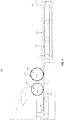
- FIG. 12 is a schematic cross-sectional view of a system 100 according to one embodiment of the present invention. By means of the illustrated system 100, the manufacturing method of the present invention can best be understood.
- the system 100 is used to produce stacked chips.
- the system 100 of the present embodiment includes a dough sheet production device 110. This may be formed as is conventional in the art.
- Device 110 preferably comprises a storage container for a dough mass (for example potato mass) which exits via a discharge in the form of a dough sheet 125 provided with at least one, particularly preferably two or more rolls. Other suitable devices for providing the dough sheet 125 are also implementable.
- the system 100 of the present embodiment also includes a treadmill 120 suitable for receiving the dough sheet 125. Preferably, dough sheet 125 slides from device 110 directly onto treadmill 120 for further transport therefrom.
- the treadmill 120 transports the dough sheet 125 to a first cutter 200.
- a first cutter 200 This preferably corresponds to that described above with reference to FIG Fig. 1A, 1B . 2 and 3
- dough that is pricked out of the dough sheet 125 by the pruning device 200 is transported through the openings 232 in the support surface 230 into the interior of the pruning device 200, where the screw 210 ejects the dough laterally from the roller of the pruning device 200 From where the dough is returned to the device 110 and in the dough mixer.
- the roller of the cutter 200 is rotatably mounted about the roller axis W1 and such that the radially outer Ausstechrand the cutter 14 engages with the treadmill 120.
- the cutter 200 substantially pierces openings in the dough sheet 125 having a diameter of about 2mm - 10mm, preferably 3mm - 8mm or a cross-sectional area of about 3mm 2 - have 80mm 2 , preferably 10mm 2 - 60mm 2 .
- the dough sheet 125 thus provided is transported by the treadmill 120 further to a second piercing device 140 having a second roller.
- the second cut-out device 140 preferably corresponds to that described above with reference to FIG Fig. 4
- the roller of the second piercer 140 is disposed downstream of the first piercer 200 with respect to the running direction of the treadmill 120, and adapted to pierce an outline of a stacked chip blank with the biscuit cutters 144.
- the resulting Teignetz via a riser (not shown) is removed and the planetokenen dough pieces remain on the conveyor belt and are transported to the deep fryer.
- the second roller has no openings, are transported to the dough residues, and thus no internal screw thread.
- this is done directly with the latter of the two Ausstechvortician.
- the portion of the dough sheet 120 surrounding the cookie cutters 144 may be sucked by a vacuum to the second cutler and later suitably removed from the roll during rotation (repelled, scraped, etc.).
- the so-soaked dough is discharged via the interior of the second piercer 140 in a similar manner as described in connection with the piercer 200, ie via openings in the carrier surface 142 and a worm thread provided in the roller of the second piercer 140 , The dough pieces thus separated from the dough pieces are also returned to the apparatus 110.
- the stacked chip forming system 100 further includes a movable cooking rack 160 having a plurality of cylindrically curved surfaces each having a plurality of holes and adapted to receive the dough pieces outlined by the first and second cutters 200, 140 with a stacked chip blank outline continuously absorb on the cylindrically curved surface.
- the dough pieces are brought by means of the conveyor belt to the deep fryer and run over a fryer inlet conveyor belt (not shown) in the deep fryer, where they are each received by the Garhalterept.
- the movable cooking fixture 160 removes the dough pieces directly from the last piercer 140 or 200.
- the system in this embodiment includes a baking device, preferably a fryer 150, with the cooking support 160 adapted to dip into the fryer 150 so that the dough pieces being punched out on the cooking fixture 160 are baked in the fat of the fryer 150.
- the stack chips are seasoned, e.g. with a seasoning or dry seasoning, and packed.
- the present invention further relates to the use of a cutter 200 as described above in a method as described above in connection with the system and described below.
- the method in one embodiment of the present invention is to form stacked chips and includes providing a dough sheet on a treadmill, transporting the dough sheet by means of the treadmill, cutting out dough openings in the dough sheet by means of a first piercer, and cutting out dough pieces by a second one Cutter, whereby dough pieces are formed with the outline of a stacked chip blank, each piece of dough having at least one dough openings cut out by the first canning device and the baking of the dough pieces.
- the first cut-out device preferably corresponds to the first cut-out device 200 of the above description.
- the dough openings are pierced through the piercing wall and the punched dough is transported through the openings in the carrier surface to the interior of the roller so that the protrusion of the piercing wall protrudes Keeping dough in the interior prevents the dough from flowing out of the interior.
- the method of forming stacked chips in a preferred embodiment further comprises transporting the dough excavated by the first piercer by means of an internal screw thread and returning the punched dough so that it is used in the step of providing a dough sheet.
- the dough moisture of the above blends may be between 37-42% by weight.
Landscapes
- Life Sciences & Earth Sciences (AREA)
- Engineering & Computer Science (AREA)
- Food Science & Technology (AREA)
- Confectionery (AREA)
- Noodles (AREA)
- Preparation Of Fruits And Vegetables (AREA)
- Bakery Products And Manufacturing Methods Therefor (AREA)
- Manufacturing And Processing Devices For Dough (AREA)
Priority Applications (11)
| Application Number | Priority Date | Filing Date | Title |
|---|---|---|---|
| RS20200703A RS60523B1 (sr) | 2017-01-13 | 2017-01-13 | Postupak i sistem za proizvodnju snek proizvoda od testa |
| PL17151355T PL3348145T3 (pl) | 2017-01-13 | 2017-01-13 | Sposób i system do wytwarzania przekąsek z ciasta |
| ES17151355T ES2797273T3 (es) | 2017-01-13 | 2017-01-13 | Procedimiento y sistema para la fabricación de productos de picoteo de pasta |
| SI201730300T SI3348145T1 (sl) | 2017-01-13 | 2017-01-13 | Postopek in sistem za izdelavo testenih prigrizkov |
| HUE17151355A HUE050739T2 (hu) | 2017-01-13 | 2017-01-13 | Eljárás és rendszer tészta snack-termékek elõállítására |
| LTEP17151355.9T LT3348145T (lt) | 2017-01-13 | 2017-01-13 | Tešlos užkandžių gaminių gamybos būdas ir sistema |
| EP17151355.9A EP3348145B1 (fr) | 2017-01-13 | 2017-01-13 | Procédé et système de fabrication d'en-cas à base de pâte |
| DK17151355.9T DK3348145T3 (da) | 2017-01-13 | 2017-01-13 | Fremgangsmåde og system til produktion af dej-snack-produkter |
| PT171513559T PT3348145T (pt) | 2017-01-13 | 2017-01-13 | Método e sistema para o fabrico de produtos à base de massa |
| CY20201100492T CY1123232T1 (el) | 2017-01-13 | 2020-06-01 | Μεθοδος, μηχανισμος αποκοπης και συστημα για την παρασκευη προϊοντων προχειρου φαγητου απο ζυμαρι |
| HRP20200963TT HRP20200963T1 (hr) | 2017-01-13 | 2020-06-17 | Postupak i sustav proizvodnje grickalica od tijesta |
Applications Claiming Priority (1)
| Application Number | Priority Date | Filing Date | Title |
|---|---|---|---|
| EP17151355.9A EP3348145B1 (fr) | 2017-01-13 | 2017-01-13 | Procédé et système de fabrication d'en-cas à base de pâte |
Publications (2)
| Publication Number | Publication Date |
|---|---|
| EP3348145A1 true EP3348145A1 (fr) | 2018-07-18 |
| EP3348145B1 EP3348145B1 (fr) | 2020-03-18 |
Family
ID=57799590
Family Applications (1)
| Application Number | Title | Priority Date | Filing Date |
|---|---|---|---|
| EP17151355.9A Active EP3348145B1 (fr) | 2017-01-13 | 2017-01-13 | Procédé et système de fabrication d'en-cas à base de pâte |
Country Status (11)
| Country | Link |
|---|---|
| EP (1) | EP3348145B1 (fr) |
| CY (1) | CY1123232T1 (fr) |
| DK (1) | DK3348145T3 (fr) |
| ES (1) | ES2797273T3 (fr) |
| HR (1) | HRP20200963T1 (fr) |
| HU (1) | HUE050739T2 (fr) |
| LT (1) | LT3348145T (fr) |
| PL (1) | PL3348145T3 (fr) |
| PT (1) | PT3348145T (fr) |
| RS (1) | RS60523B1 (fr) |
| SI (1) | SI3348145T1 (fr) |
Cited By (1)
| Publication number | Priority date | Publication date | Assignee | Title |
|---|---|---|---|---|
| CN109566688A (zh) * | 2018-11-30 | 2019-04-05 | 安徽中乐食品机械有限公司 | 一种用于披萨自动生产线的披萨成型装置 |
Families Citing this family (1)
| Publication number | Priority date | Publication date | Assignee | Title |
|---|---|---|---|---|
| GB202012827D0 (en) * | 2020-08-17 | 2020-09-30 | Signature Flatbreads Uk Ltd | Cutting tool |
Citations (5)
| Publication number | Priority date | Publication date | Assignee | Title |
|---|---|---|---|---|
| US3724980A (en) * | 1970-12-19 | 1973-04-03 | Briem Hengler Cronemeyer | Apparatus for cutting out forms from a ribbon of dough |
| FR2165275A5 (en) * | 1971-12-23 | 1973-08-03 | Billiard & Cie | Industrial pastry cutter - separate case and lid blanks cut simultaneously from superimposed pastry sheets |
| US5127292A (en) * | 1990-10-22 | 1992-07-07 | Vinod Kapoor | Apparatus and method for cutting and removing thin transverse strips from a moving web |
| WO2007050995A1 (fr) * | 2005-10-27 | 2007-05-03 | Eagle Rotary Systems, Inc. | Appareil servant a retirer les chutes d'un outil de coupe rotatif |
| ES2549878T3 (es) * | 2007-09-12 | 2015-11-02 | Werner & Pfleiderer Industrielle Backtechnik Gmbh | Rodillo cortador para cortar trozos de masa de una capa de masa, así como equipo para el procesamiento de masas con un rodillo cortador de este tipo |
Family Cites Families (1)
| Publication number | Priority date | Publication date | Assignee | Title |
|---|---|---|---|---|
| US5306133A (en) * | 1993-01-21 | 1994-04-26 | Miles J. Willard | Dough sheet rotary cutting system |
-
2017
- 2017-01-13 SI SI201730300T patent/SI3348145T1/sl unknown
- 2017-01-13 PT PT171513559T patent/PT3348145T/pt unknown
- 2017-01-13 DK DK17151355.9T patent/DK3348145T3/da active
- 2017-01-13 LT LTEP17151355.9T patent/LT3348145T/lt unknown
- 2017-01-13 PL PL17151355T patent/PL3348145T3/pl unknown
- 2017-01-13 ES ES17151355T patent/ES2797273T3/es active Active
- 2017-01-13 RS RS20200703A patent/RS60523B1/sr unknown
- 2017-01-13 HU HUE17151355A patent/HUE050739T2/hu unknown
- 2017-01-13 EP EP17151355.9A patent/EP3348145B1/fr active Active
-
2020
- 2020-06-01 CY CY20201100492T patent/CY1123232T1/el unknown
- 2020-06-17 HR HRP20200963TT patent/HRP20200963T1/hr unknown
Patent Citations (5)
| Publication number | Priority date | Publication date | Assignee | Title |
|---|---|---|---|---|
| US3724980A (en) * | 1970-12-19 | 1973-04-03 | Briem Hengler Cronemeyer | Apparatus for cutting out forms from a ribbon of dough |
| FR2165275A5 (en) * | 1971-12-23 | 1973-08-03 | Billiard & Cie | Industrial pastry cutter - separate case and lid blanks cut simultaneously from superimposed pastry sheets |
| US5127292A (en) * | 1990-10-22 | 1992-07-07 | Vinod Kapoor | Apparatus and method for cutting and removing thin transverse strips from a moving web |
| WO2007050995A1 (fr) * | 2005-10-27 | 2007-05-03 | Eagle Rotary Systems, Inc. | Appareil servant a retirer les chutes d'un outil de coupe rotatif |
| ES2549878T3 (es) * | 2007-09-12 | 2015-11-02 | Werner & Pfleiderer Industrielle Backtechnik Gmbh | Rodillo cortador para cortar trozos de masa de una capa de masa, así como equipo para el procesamiento de masas con un rodillo cortador de este tipo |
Cited By (1)
| Publication number | Priority date | Publication date | Assignee | Title |
|---|---|---|---|---|
| CN109566688A (zh) * | 2018-11-30 | 2019-04-05 | 安徽中乐食品机械有限公司 | 一种用于披萨自动生产线的披萨成型装置 |
Also Published As
| Publication number | Publication date |
|---|---|
| CY1123232T1 (el) | 2021-10-29 |
| HUE050739T2 (hu) | 2021-01-28 |
| PT3348145T (pt) | 2020-06-25 |
| LT3348145T (lt) | 2020-07-10 |
| HRP20200963T1 (hr) | 2020-10-02 |
| EP3348145B1 (fr) | 2020-03-18 |
| ES2797273T3 (es) | 2020-12-01 |
| SI3348145T1 (sl) | 2020-08-31 |
| DK3348145T3 (da) | 2020-06-22 |
| RS60523B1 (sr) | 2020-08-31 |
| PL3348145T3 (pl) | 2020-11-02 |
Similar Documents
| Publication | Publication Date | Title |
|---|---|---|
| DE69513176T2 (de) | Verfahren zur herstellung verbesserter wellenförmiger imbiss-chips | |
| DE2841398C2 (fr) | ||
| US7914834B2 (en) | Method of forming food product | |
| DE3544576C2 (fr) | ||
| DE1532949A1 (de) | Verfahren und Einrichtung zur Herstellung von pastetenartigen Nahrungsmitteln | |
| DE69512405T2 (de) | Verbesserungen in der herstellung von nahrungsmittelprodukten | |
| DE60216444T2 (de) | Gefülltes Backwarenerzeugnis und Verfahren zur Herstellung | |
| CH644993A5 (de) | Verfahren und anordnung zur kontinuierlichen herstellung einer aus nahrungsmittelschichten bestehenden bahn. | |
| DE2413470C2 (de) | Einrichtung zur Fabrikation von Chips oder Flocken aus Nahrungs-, Genuß- oder Futtermitteln wie Früchten, Gemüsen, Kartoffeln od.dgl. | |
| EP3348145A1 (fr) | Procédé, emporte-pièce et système de fabrication d'en-cas à base de pâte | |
| DE69709506T2 (de) | Verfahren und Vorrichtung zur Herstellung von Produkten mit einem vorspringenden Rand | |
| DE69016670T2 (de) | Imbissprodukte. | |
| DE602005004421T2 (de) | Essbare verpackung für lebensmittel und verfahren zu deren herstellung | |
| DE1792406B2 (de) | Verfahren zur Herstellung von für Backzwecke geeigneten plastischen Speisefetten | |
| DE602004003790T2 (de) | Verfahren zur Herstellung von Cracker | |
| EP2225944B1 (fr) | Procédé et dispositif de fabrication de produits cuits plats dotés d'une face inférieure à ports ouverts | |
| EP2989896B1 (fr) | Produit de boulangerie à motif | |
| DE2552573A1 (de) | Verfahren und vorrichtung zur herstellung chipartiger nahrungsmittelprodukte | |
| EP0387669B1 (fr) | Appareil pour la production de petits pains incisés | |
| DE2358433A1 (de) | Kartoffel-knabberartikel | |
| DE202006019470U1 (de) | Teigformungsvorrichtung und -system | |
| DE102005037590B4 (de) | Back- und Gärform und ein Verfahren zur Herstellung eines Backprodukts aus Hefeteig | |
| AT516486B1 (de) | Pressvorrichtung | |
| EP0276456B1 (fr) | Méthode et appareil pour la production de galettes croustillantes | |
| DE202024001894U1 (de) | Lebensmittel für Brotröster |
Legal Events
| Date | Code | Title | Description |
|---|---|---|---|
| PUAI | Public reference made under article 153(3) epc to a published international application that has entered the european phase |
Free format text: ORIGINAL CODE: 0009012 |
|
| STAA | Information on the status of an ep patent application or granted ep patent |
Free format text: STATUS: THE APPLICATION HAS BEEN PUBLISHED |
|
| AK | Designated contracting states |
Kind code of ref document: A1 Designated state(s): AL AT BE BG CH CY CZ DE DK EE ES FI FR GB GR HR HU IE IS IT LI LT LU LV MC MK MT NL NO PL PT RO RS SE SI SK SM TR |
|
| AX | Request for extension of the european patent |
Extension state: BA ME |
|
| STAA | Information on the status of an ep patent application or granted ep patent |
Free format text: STATUS: REQUEST FOR EXAMINATION WAS MADE |
|
| 17P | Request for examination filed |
Effective date: 20190114 |
|
| RBV | Designated contracting states (corrected) |
Designated state(s): AL AT BE BG CH CY CZ DE DK EE ES FI FR GB GR HR HU IE IS IT LI LT LU LV MC MK MT NL NO PL PT RO RS SE SI SK SM TR |
|
| STAA | Information on the status of an ep patent application or granted ep patent |
Free format text: STATUS: EXAMINATION IS IN PROGRESS |
|
| 17Q | First examination report despatched |
Effective date: 20190723 |
|
| GRAP | Despatch of communication of intention to grant a patent |
Free format text: ORIGINAL CODE: EPIDOSNIGR1 |
|
| STAA | Information on the status of an ep patent application or granted ep patent |
Free format text: STATUS: GRANT OF PATENT IS INTENDED |
|
| INTG | Intention to grant announced |
Effective date: 20191010 |
|
| GRAS | Grant fee paid |
Free format text: ORIGINAL CODE: EPIDOSNIGR3 |
|
| GRAA | (expected) grant |
Free format text: ORIGINAL CODE: 0009210 |
|
| STAA | Information on the status of an ep patent application or granted ep patent |
Free format text: STATUS: THE PATENT HAS BEEN GRANTED |
|
| AK | Designated contracting states |
Kind code of ref document: B1 Designated state(s): AL AT BE BG CH CY CZ DE DK EE ES FI FR GB GR HR HU IE IS IT LI LT LU LV MC MK MT NL NO PL PT RO RS SE SI SK SM TR |
|
| REG | Reference to a national code |
Ref country code: GB Ref legal event code: FG4D Free format text: NOT ENGLISH |
|
| REG | Reference to a national code |
Ref country code: DE Ref legal event code: R096 Ref document number: 502017004244 Country of ref document: DE |
|
| REG | Reference to a national code |
Ref country code: AT Ref legal event code: REF Ref document number: 1244858 Country of ref document: AT Kind code of ref document: T Effective date: 20200415 Ref country code: IE Ref legal event code: FG4D Free format text: LANGUAGE OF EP DOCUMENT: GERMAN |
|
| REG | Reference to a national code |
Ref country code: FI Ref legal event code: FGE |
|
| REG | Reference to a national code |
Ref country code: NL Ref legal event code: FP |
|
| REG | Reference to a national code |
Ref country code: DK Ref legal event code: T3 Effective date: 20200617 Ref country code: NO Ref legal event code: T2 Effective date: 20200318 |
|
| REG | Reference to a national code |
Ref country code: PT Ref legal event code: SC4A Ref document number: 3348145 Country of ref document: PT Date of ref document: 20200625 Kind code of ref document: T Free format text: AVAILABILITY OF NATIONAL TRANSLATION Effective date: 20200616 |
|
| REG | Reference to a national code |
Ref country code: CH Ref legal event code: NV Representative=s name: DENNEMEYER AG, CH |
|
| REG | Reference to a national code |
Ref country code: SE Ref legal event code: TRGR |
|
| REG | Reference to a national code |
Ref country code: GR Ref legal event code: EP Ref document number: 20200401556 Country of ref document: GR Effective date: 20200716 |
|
| REG | Reference to a national code |
Ref country code: SK Ref legal event code: T3 Ref document number: E 34417 Country of ref document: SK |
|
| REG | Reference to a national code |
Ref country code: EE Ref legal event code: FG4A Ref document number: E019261 Country of ref document: EE Effective date: 20200521 |
|
| REG | Reference to a national code |
Ref country code: HR Ref legal event code: T1PR Ref document number: P20200963 Country of ref document: HR |
|
| PG25 | Lapsed in a contracting state [announced via postgrant information from national office to epo] |
Ref country code: SM Free format text: LAPSE BECAUSE OF FAILURE TO SUBMIT A TRANSLATION OF THE DESCRIPTION OR TO PAY THE FEE WITHIN THE PRESCRIBED TIME-LIMIT Effective date: 20200318 Ref country code: IS Free format text: LAPSE BECAUSE OF FAILURE TO SUBMIT A TRANSLATION OF THE DESCRIPTION OR TO PAY THE FEE WITHIN THE PRESCRIBED TIME-LIMIT Effective date: 20200718 |
|
| REG | Reference to a national code |
Ref country code: ES Ref legal event code: FG2A Ref document number: 2797273 Country of ref document: ES Kind code of ref document: T3 Effective date: 20201201 |
|
| REG | Reference to a national code |
Ref country code: DE Ref legal event code: R097 Ref document number: 502017004244 Country of ref document: DE |
|
| PLBE | No opposition filed within time limit |
Free format text: ORIGINAL CODE: 0009261 |
|
| REG | Reference to a national code |
Ref country code: HR Ref legal event code: ODRP Ref document number: P20200963 Country of ref document: HR Payment date: 20210108 Year of fee payment: 5 |
|
| STAA | Information on the status of an ep patent application or granted ep patent |
Free format text: STATUS: NO OPPOSITION FILED WITHIN TIME LIMIT |
|
| REG | Reference to a national code |
Ref country code: HU Ref legal event code: AG4A Ref document number: E050739 Country of ref document: HU |
|
| 26N | No opposition filed |
Effective date: 20201221 |
|
| PG25 | Lapsed in a contracting state [announced via postgrant information from national office to epo] |
Ref country code: MC Free format text: LAPSE BECAUSE OF FAILURE TO SUBMIT A TRANSLATION OF THE DESCRIPTION OR TO PAY THE FEE WITHIN THE PRESCRIBED TIME-LIMIT Effective date: 20200318 |
|
| REG | Reference to a national code |
Ref country code: HR Ref legal event code: ODRP Ref document number: P20200963 Country of ref document: HR Payment date: 20220110 Year of fee payment: 6 |
|
| REG | Reference to a national code |
Ref country code: HR Ref legal event code: ODRP Ref document number: P20200963 Country of ref document: HR Payment date: 20230104 Year of fee payment: 7 |
|
| REG | Reference to a national code |
Ref country code: HR Ref legal event code: ODRP Ref document number: P20200963 Country of ref document: HR Payment date: 20240105 Year of fee payment: 8 |
|
| REG | Reference to a national code |
Ref country code: HR Ref legal event code: ODRP Ref document number: P20200963 Country of ref document: HR Payment date: 20250107 Year of fee payment: 9 |
|
| PGFP | Annual fee paid to national office [announced via postgrant information from national office to epo] |
Ref country code: BG Payment date: 20250121 Year of fee payment: 9 |
|
| PGFP | Annual fee paid to national office [announced via postgrant information from national office to epo] |
Ref country code: SI Payment date: 20250106 Year of fee payment: 9 |
|
| PGFP | Annual fee paid to national office [announced via postgrant information from national office to epo] |
Ref country code: AL Payment date: 20250122 Year of fee payment: 9 |
|
| PGFP | Annual fee paid to national office [announced via postgrant information from national office to epo] |
Ref country code: MK Payment date: 20241230 Year of fee payment: 9 |
|
| REG | Reference to a national code |
Ref country code: HR Ref legal event code: ODRP Ref document number: P20200963 Country of ref document: HR Payment date: 20260108 Year of fee payment: 10 |
|
| REG | Reference to a national code |
Ref country code: CH Ref legal event code: U11 Free format text: ST27 STATUS EVENT CODE: U-0-0-U10-U11 (AS PROVIDED BY THE NATIONAL OFFICE) Effective date: 20260201 |
|
| PGFP | Annual fee paid to national office [announced via postgrant information from national office to epo] |
Ref country code: LU Payment date: 20260121 Year of fee payment: 10 Ref country code: NL Payment date: 20260121 Year of fee payment: 10 |
|
| PGFP | Annual fee paid to national office [announced via postgrant information from national office to epo] |
Ref country code: HU Payment date: 20260113 Year of fee payment: 10 |
|
| PGFP | Annual fee paid to national office [announced via postgrant information from national office to epo] |
Ref country code: SE Payment date: 20260121 Year of fee payment: 10 |
|
| PGFP | Annual fee paid to national office [announced via postgrant information from national office to epo] |
Ref country code: GB Payment date: 20260122 Year of fee payment: 10 Ref country code: LT Payment date: 20260105 Year of fee payment: 10 |
|
| PGFP | Annual fee paid to national office [announced via postgrant information from national office to epo] |
Ref country code: ES Payment date: 20260217 Year of fee payment: 10 |
|
| PGFP | Annual fee paid to national office [announced via postgrant information from national office to epo] |
Ref country code: DE Payment date: 20260126 Year of fee payment: 10 Ref country code: NO Payment date: 20260120 Year of fee payment: 10 Ref country code: DK Payment date: 20260121 Year of fee payment: 10 Ref country code: IE Payment date: 20260121 Year of fee payment: 10 |
|
| PGFP | Annual fee paid to national office [announced via postgrant information from national office to epo] |
Ref country code: AT Payment date: 20260119 Year of fee payment: 10 Ref country code: HR Payment date: 20260108 Year of fee payment: 10 |
|
| PGFP | Annual fee paid to national office [announced via postgrant information from national office to epo] |
Ref country code: FI Payment date: 20260120 Year of fee payment: 10 Ref country code: RO Payment date: 20260112 Year of fee payment: 10 Ref country code: BE Payment date: 20260121 Year of fee payment: 10 Ref country code: IT Payment date: 20260130 Year of fee payment: 10 |
|
| PGFP | Annual fee paid to national office [announced via postgrant information from national office to epo] |
Ref country code: RS Payment date: 20260109 Year of fee payment: 10 |
|
| PGFP | Annual fee paid to national office [announced via postgrant information from national office to epo] |
Ref country code: FR Payment date: 20260121 Year of fee payment: 10 |
|
| PGFP | Annual fee paid to national office [announced via postgrant information from national office to epo] |
Ref country code: TR Payment date: 20260112 Year of fee payment: 10 |
|
| PGFP | Annual fee paid to national office [announced via postgrant information from national office to epo] |
Ref country code: PT Payment date: 20260112 Year of fee payment: 10 Ref country code: CZ Payment date: 20260102 Year of fee payment: 10 Ref country code: CH Payment date: 20260201 Year of fee payment: 10 |
|
| PGFP | Annual fee paid to national office [announced via postgrant information from national office to epo] |
Ref country code: GR Payment date: 20260119 Year of fee payment: 10 Ref country code: PL Payment date: 20260102 Year of fee payment: 10 Ref country code: CY Payment date: 20260107 Year of fee payment: 10 Ref country code: MT Payment date: 20260126 Year of fee payment: 10 |
|
| PGFP | Annual fee paid to national office [announced via postgrant information from national office to epo] |
Ref country code: EE Payment date: 20260130 Year of fee payment: 10 Ref country code: SK Payment date: 20260107 Year of fee payment: 10 Ref country code: LV Payment date: 20260120 Year of fee payment: 10 |