EP3348444A1 - Système et procédé de contrôle de stabilité pour véhicule électrique à quatre roues motrices, et véhicule électrique - Google Patents
Système et procédé de contrôle de stabilité pour véhicule électrique à quatre roues motrices, et véhicule électrique Download PDFInfo
- Publication number
- EP3348444A1 EP3348444A1 EP16834666.6A EP16834666A EP3348444A1 EP 3348444 A1 EP3348444 A1 EP 3348444A1 EP 16834666 A EP16834666 A EP 16834666A EP 3348444 A1 EP3348444 A1 EP 3348444A1
- Authority
- EP
- European Patent Office
- Prior art keywords
- electric vehicle
- braking force
- wheel
- stability control
- vehicle
- Prior art date
- Legal status (The legal status is an assumption and is not a legal conclusion. Google has not performed a legal analysis and makes no representation as to the accuracy of the status listed.)
- Granted
Links
Images



Classifications
-
- B—PERFORMING OPERATIONS; TRANSPORTING
- B60—VEHICLES IN GENERAL
- B60T—VEHICLE BRAKE CONTROL SYSTEMS OR PARTS THEREOF; BRAKE CONTROL SYSTEMS OR PARTS THEREOF, IN GENERAL; ARRANGEMENT OF BRAKING ELEMENTS ON VEHICLES IN GENERAL; PORTABLE DEVICES FOR PREVENTING UNWANTED MOVEMENT OF VEHICLES; VEHICLE MODIFICATIONS TO FACILITATE COOLING OF BRAKES
- B60T8/00—Arrangements for adjusting wheel-braking force to meet varying vehicular or ground-surface conditions, e.g. limiting or varying distribution of braking force
- B60T8/17—Using electrical or electronic regulation means to control braking
- B60T8/1755—Brake regulation specially adapted to control the stability of the vehicle, e.g. taking into account yaw rate or transverse acceleration in a curve
- B60T8/17551—Brake regulation specially adapted to control the stability of the vehicle, e.g. taking into account yaw rate or transverse acceleration in a curve determining control parameters related to vehicle stability used in the regulation, e.g. by calculations involving measured or detected parameters
-
- B—PERFORMING OPERATIONS; TRANSPORTING
- B60—VEHICLES IN GENERAL
- B60L—PROPULSION OF ELECTRICALLY-PROPELLED VEHICLES; SUPPLYING ELECTRIC POWER FOR AUXILIARY EQUIPMENT OF ELECTRICALLY-PROPELLED VEHICLES; ELECTRODYNAMIC BRAKE SYSTEMS FOR VEHICLES IN GENERAL; MAGNETIC SUSPENSION OR LEVITATION FOR VEHICLES; MONITORING OPERATING VARIABLES OF ELECTRICALLY-PROPELLED VEHICLES; ELECTRIC SAFETY DEVICES FOR ELECTRICALLY-PROPELLED VEHICLES
- B60L7/00—Electrodynamic brake systems for vehicles in general
- B60L7/10—Dynamic electric regenerative braking
- B60L7/18—Controlling the braking effect
-
- B—PERFORMING OPERATIONS; TRANSPORTING
- B60—VEHICLES IN GENERAL
- B60T—VEHICLE BRAKE CONTROL SYSTEMS OR PARTS THEREOF; BRAKE CONTROL SYSTEMS OR PARTS THEREOF, IN GENERAL; ARRANGEMENT OF BRAKING ELEMENTS ON VEHICLES IN GENERAL; PORTABLE DEVICES FOR PREVENTING UNWANTED MOVEMENT OF VEHICLES; VEHICLE MODIFICATIONS TO FACILITATE COOLING OF BRAKES
- B60T13/00—Transmitting braking action from initiating means to ultimate brake actuator with power assistance or drive; Brake systems incorporating such transmitting means, e.g. air-pressure brake systems
- B60T13/74—Transmitting braking action from initiating means to ultimate brake actuator with power assistance or drive; Brake systems incorporating such transmitting means, e.g. air-pressure brake systems with electrical assistance or drive
- B60T13/741—Transmitting braking action from initiating means to ultimate brake actuator with power assistance or drive; Brake systems incorporating such transmitting means, e.g. air-pressure brake systems with electrical assistance or drive acting on an ultimate actuator
-
- B—PERFORMING OPERATIONS; TRANSPORTING
- B60—VEHICLES IN GENERAL
- B60T—VEHICLE BRAKE CONTROL SYSTEMS OR PARTS THEREOF; BRAKE CONTROL SYSTEMS OR PARTS THEREOF, IN GENERAL; ARRANGEMENT OF BRAKING ELEMENTS ON VEHICLES IN GENERAL; PORTABLE DEVICES FOR PREVENTING UNWANTED MOVEMENT OF VEHICLES; VEHICLE MODIFICATIONS TO FACILITATE COOLING OF BRAKES
- B60T8/00—Arrangements for adjusting wheel-braking force to meet varying vehicular or ground-surface conditions, e.g. limiting or varying distribution of braking force
- B60T8/17—Using electrical or electronic regulation means to control braking
- B60T8/171—Detecting parameters used in the regulation; Measuring values used in the regulation
-
- B—PERFORMING OPERATIONS; TRANSPORTING
- B60—VEHICLES IN GENERAL
- B60T—VEHICLE BRAKE CONTROL SYSTEMS OR PARTS THEREOF; BRAKE CONTROL SYSTEMS OR PARTS THEREOF, IN GENERAL; ARRANGEMENT OF BRAKING ELEMENTS ON VEHICLES IN GENERAL; PORTABLE DEVICES FOR PREVENTING UNWANTED MOVEMENT OF VEHICLES; VEHICLE MODIFICATIONS TO FACILITATE COOLING OF BRAKES
- B60T8/00—Arrangements for adjusting wheel-braking force to meet varying vehicular or ground-surface conditions, e.g. limiting or varying distribution of braking force
- B60T8/17—Using electrical or electronic regulation means to control braking
- B60T8/172—Determining control parameters used in the regulation, e.g. by calculations involving measured or detected parameters
-
- B—PERFORMING OPERATIONS; TRANSPORTING
- B60—VEHICLES IN GENERAL
- B60T—VEHICLE BRAKE CONTROL SYSTEMS OR PARTS THEREOF; BRAKE CONTROL SYSTEMS OR PARTS THEREOF, IN GENERAL; ARRANGEMENT OF BRAKING ELEMENTS ON VEHICLES IN GENERAL; PORTABLE DEVICES FOR PREVENTING UNWANTED MOVEMENT OF VEHICLES; VEHICLE MODIFICATIONS TO FACILITATE COOLING OF BRAKES
- B60T8/00—Arrangements for adjusting wheel-braking force to meet varying vehicular or ground-surface conditions, e.g. limiting or varying distribution of braking force
- B60T8/17—Using electrical or electronic regulation means to control braking
- B60T8/1755—Brake regulation specially adapted to control the stability of the vehicle, e.g. taking into account yaw rate or transverse acceleration in a curve
- B60T8/17552—Brake regulation specially adapted to control the stability of the vehicle, e.g. taking into account yaw rate or transverse acceleration in a curve responsive to the tyre sideslip angle or the vehicle body slip angle
-
- B—PERFORMING OPERATIONS; TRANSPORTING
- B60—VEHICLES IN GENERAL
- B60T—VEHICLE BRAKE CONTROL SYSTEMS OR PARTS THEREOF; BRAKE CONTROL SYSTEMS OR PARTS THEREOF, IN GENERAL; ARRANGEMENT OF BRAKING ELEMENTS ON VEHICLES IN GENERAL; PORTABLE DEVICES FOR PREVENTING UNWANTED MOVEMENT OF VEHICLES; VEHICLE MODIFICATIONS TO FACILITATE COOLING OF BRAKES
- B60T8/00—Arrangements for adjusting wheel-braking force to meet varying vehicular or ground-surface conditions, e.g. limiting or varying distribution of braking force
- B60T8/17—Using electrical or electronic regulation means to control braking
- B60T8/1755—Brake regulation specially adapted to control the stability of the vehicle, e.g. taking into account yaw rate or transverse acceleration in a curve
- B60T8/17554—Brake regulation specially adapted to control the stability of the vehicle, e.g. taking into account yaw rate or transverse acceleration in a curve specially adapted for enhancing stability around the vehicles longitudinal axle, i.e. roll-over prevention
-
- B—PERFORMING OPERATIONS; TRANSPORTING
- B60—VEHICLES IN GENERAL
- B60T—VEHICLE BRAKE CONTROL SYSTEMS OR PARTS THEREOF; BRAKE CONTROL SYSTEMS OR PARTS THEREOF, IN GENERAL; ARRANGEMENT OF BRAKING ELEMENTS ON VEHICLES IN GENERAL; PORTABLE DEVICES FOR PREVENTING UNWANTED MOVEMENT OF VEHICLES; VEHICLE MODIFICATIONS TO FACILITATE COOLING OF BRAKES
- B60T8/00—Arrangements for adjusting wheel-braking force to meet varying vehicular or ground-surface conditions, e.g. limiting or varying distribution of braking force
- B60T8/17—Using electrical or electronic regulation means to control braking
- B60T8/176—Brake regulation specially adapted to prevent excessive wheel slip during vehicle deceleration, e.g. ABS
- B60T8/1769—Brake regulation specially adapted to prevent excessive wheel slip during vehicle deceleration, e.g. ABS specially adapted for vehicles having more than one driven axle, e.g. four-wheel drive vehicles
-
- B—PERFORMING OPERATIONS; TRANSPORTING
- B60—VEHICLES IN GENERAL
- B60T—VEHICLE BRAKE CONTROL SYSTEMS OR PARTS THEREOF; BRAKE CONTROL SYSTEMS OR PARTS THEREOF, IN GENERAL; ARRANGEMENT OF BRAKING ELEMENTS ON VEHICLES IN GENERAL; PORTABLE DEVICES FOR PREVENTING UNWANTED MOVEMENT OF VEHICLES; VEHICLE MODIFICATIONS TO FACILITATE COOLING OF BRAKES
- B60T8/00—Arrangements for adjusting wheel-braking force to meet varying vehicular or ground-surface conditions, e.g. limiting or varying distribution of braking force
- B60T8/26—Arrangements for adjusting wheel-braking force to meet varying vehicular or ground-surface conditions, e.g. limiting or varying distribution of braking force characterised by producing differential braking between front and rear wheels
- B60T8/30—Arrangements for adjusting wheel-braking force to meet varying vehicular or ground-surface conditions, e.g. limiting or varying distribution of braking force characterised by producing differential braking between front and rear wheels responsive to load
-
- B—PERFORMING OPERATIONS; TRANSPORTING
- B60—VEHICLES IN GENERAL
- B60T—VEHICLE BRAKE CONTROL SYSTEMS OR PARTS THEREOF; BRAKE CONTROL SYSTEMS OR PARTS THEREOF, IN GENERAL; ARRANGEMENT OF BRAKING ELEMENTS ON VEHICLES IN GENERAL; PORTABLE DEVICES FOR PREVENTING UNWANTED MOVEMENT OF VEHICLES; VEHICLE MODIFICATIONS TO FACILITATE COOLING OF BRAKES
- B60T8/00—Arrangements for adjusting wheel-braking force to meet varying vehicular or ground-surface conditions, e.g. limiting or varying distribution of braking force
- B60T8/32—Arrangements for adjusting wheel-braking force to meet varying vehicular or ground-surface conditions, e.g. limiting or varying distribution of braking force responsive to a speed condition, e.g. acceleration or deceleration
- B60T8/3205—Arrangements for adjusting wheel-braking force to meet varying vehicular or ground-surface conditions, e.g. limiting or varying distribution of braking force responsive to a speed condition, e.g. acceleration or deceleration acceleration
-
- B—PERFORMING OPERATIONS; TRANSPORTING
- B60—VEHICLES IN GENERAL
- B60W—CONJOINT CONTROL OF VEHICLE SUB-UNITS OF DIFFERENT TYPE OR DIFFERENT FUNCTION; CONTROL SYSTEMS SPECIALLY ADAPTED FOR HYBRID VEHICLES; ROAD VEHICLE DRIVE CONTROL SYSTEMS FOR PURPOSES NOT RELATED TO THE CONTROL OF A PARTICULAR SUB-UNIT
- B60W30/00—Purposes of road vehicle drive control systems not related to the control of a particular sub-unit, e.g. of systems using conjoint control of vehicle sub-units
- B60W30/02—Control of vehicle driving stability
- B60W30/04—Control of vehicle driving stability related to roll-over prevention
-
- B—PERFORMING OPERATIONS; TRANSPORTING
- B60—VEHICLES IN GENERAL
- B60L—PROPULSION OF ELECTRICALLY-PROPELLED VEHICLES; SUPPLYING ELECTRIC POWER FOR AUXILIARY EQUIPMENT OF ELECTRICALLY-PROPELLED VEHICLES; ELECTRODYNAMIC BRAKE SYSTEMS FOR VEHICLES IN GENERAL; MAGNETIC SUSPENSION OR LEVITATION FOR VEHICLES; MONITORING OPERATING VARIABLES OF ELECTRICALLY-PROPELLED VEHICLES; ELECTRIC SAFETY DEVICES FOR ELECTRICALLY-PROPELLED VEHICLES
- B60L2240/00—Control parameters of input or output; Target parameters
- B60L2240/10—Vehicle control parameters
- B60L2240/14—Acceleration
- B60L2240/16—Acceleration longitudinal
-
- B—PERFORMING OPERATIONS; TRANSPORTING
- B60—VEHICLES IN GENERAL
- B60L—PROPULSION OF ELECTRICALLY-PROPELLED VEHICLES; SUPPLYING ELECTRIC POWER FOR AUXILIARY EQUIPMENT OF ELECTRICALLY-PROPELLED VEHICLES; ELECTRODYNAMIC BRAKE SYSTEMS FOR VEHICLES IN GENERAL; MAGNETIC SUSPENSION OR LEVITATION FOR VEHICLES; MONITORING OPERATING VARIABLES OF ELECTRICALLY-PROPELLED VEHICLES; ELECTRIC SAFETY DEVICES FOR ELECTRICALLY-PROPELLED VEHICLES
- B60L2240/00—Control parameters of input or output; Target parameters
- B60L2240/10—Vehicle control parameters
- B60L2240/14—Acceleration
- B60L2240/18—Acceleration lateral
-
- B—PERFORMING OPERATIONS; TRANSPORTING
- B60—VEHICLES IN GENERAL
- B60L—PROPULSION OF ELECTRICALLY-PROPELLED VEHICLES; SUPPLYING ELECTRIC POWER FOR AUXILIARY EQUIPMENT OF ELECTRICALLY-PROPELLED VEHICLES; ELECTRODYNAMIC BRAKE SYSTEMS FOR VEHICLES IN GENERAL; MAGNETIC SUSPENSION OR LEVITATION FOR VEHICLES; MONITORING OPERATING VARIABLES OF ELECTRICALLY-PROPELLED VEHICLES; ELECTRIC SAFETY DEVICES FOR ELECTRICALLY-PROPELLED VEHICLES
- B60L2240/00—Control parameters of input or output; Target parameters
- B60L2240/10—Vehicle control parameters
- B60L2240/22—Yaw angle
-
- B—PERFORMING OPERATIONS; TRANSPORTING
- B60—VEHICLES IN GENERAL
- B60L—PROPULSION OF ELECTRICALLY-PROPELLED VEHICLES; SUPPLYING ELECTRIC POWER FOR AUXILIARY EQUIPMENT OF ELECTRICALLY-PROPELLED VEHICLES; ELECTRODYNAMIC BRAKE SYSTEMS FOR VEHICLES IN GENERAL; MAGNETIC SUSPENSION OR LEVITATION FOR VEHICLES; MONITORING OPERATING VARIABLES OF ELECTRICALLY-PROPELLED VEHICLES; ELECTRIC SAFETY DEVICES FOR ELECTRICALLY-PROPELLED VEHICLES
- B60L2240/00—Control parameters of input or output; Target parameters
- B60L2240/10—Vehicle control parameters
- B60L2240/24—Steering angle
-
- B—PERFORMING OPERATIONS; TRANSPORTING
- B60—VEHICLES IN GENERAL
- B60T—VEHICLE BRAKE CONTROL SYSTEMS OR PARTS THEREOF; BRAKE CONTROL SYSTEMS OR PARTS THEREOF, IN GENERAL; ARRANGEMENT OF BRAKING ELEMENTS ON VEHICLES IN GENERAL; PORTABLE DEVICES FOR PREVENTING UNWANTED MOVEMENT OF VEHICLES; VEHICLE MODIFICATIONS TO FACILITATE COOLING OF BRAKES
- B60T2230/00—Monitoring, detecting special vehicle behaviour; Counteracting thereof
- B60T2230/02—Side slip angle, attitude angle, floating angle, drift angle
-
- B—PERFORMING OPERATIONS; TRANSPORTING
- B60—VEHICLES IN GENERAL
- B60T—VEHICLE BRAKE CONTROL SYSTEMS OR PARTS THEREOF; BRAKE CONTROL SYSTEMS OR PARTS THEREOF, IN GENERAL; ARRANGEMENT OF BRAKING ELEMENTS ON VEHICLES IN GENERAL; PORTABLE DEVICES FOR PREVENTING UNWANTED MOVEMENT OF VEHICLES; VEHICLE MODIFICATIONS TO FACILITATE COOLING OF BRAKES
- B60T2230/00—Monitoring, detecting special vehicle behaviour; Counteracting thereof
- B60T2230/03—Overturn, rollover
-
- B—PERFORMING OPERATIONS; TRANSPORTING
- B60—VEHICLES IN GENERAL
- B60T—VEHICLE BRAKE CONTROL SYSTEMS OR PARTS THEREOF; BRAKE CONTROL SYSTEMS OR PARTS THEREOF, IN GENERAL; ARRANGEMENT OF BRAKING ELEMENTS ON VEHICLES IN GENERAL; PORTABLE DEVICES FOR PREVENTING UNWANTED MOVEMENT OF VEHICLES; VEHICLE MODIFICATIONS TO FACILITATE COOLING OF BRAKES
- B60T2240/00—Monitoring, detecting wheel/tyre behaviour; counteracting thereof
- B60T2240/06—Wheel load; Wheel lift
-
- B—PERFORMING OPERATIONS; TRANSPORTING
- B60—VEHICLES IN GENERAL
- B60T—VEHICLE BRAKE CONTROL SYSTEMS OR PARTS THEREOF; BRAKE CONTROL SYSTEMS OR PARTS THEREOF, IN GENERAL; ARRANGEMENT OF BRAKING ELEMENTS ON VEHICLES IN GENERAL; PORTABLE DEVICES FOR PREVENTING UNWANTED MOVEMENT OF VEHICLES; VEHICLE MODIFICATIONS TO FACILITATE COOLING OF BRAKES
- B60T2270/00—Further aspects of brake control systems not otherwise provided for
- B60T2270/30—ESP control system
- B60T2270/302—ESP control system for all-wheel drive vehicles
-
- B—PERFORMING OPERATIONS; TRANSPORTING
- B60—VEHICLES IN GENERAL
- B60T—VEHICLE BRAKE CONTROL SYSTEMS OR PARTS THEREOF; BRAKE CONTROL SYSTEMS OR PARTS THEREOF, IN GENERAL; ARRANGEMENT OF BRAKING ELEMENTS ON VEHICLES IN GENERAL; PORTABLE DEVICES FOR PREVENTING UNWANTED MOVEMENT OF VEHICLES; VEHICLE MODIFICATIONS TO FACILITATE COOLING OF BRAKES
- B60T2270/00—Further aspects of brake control systems not otherwise provided for
- B60T2270/60—Regenerative braking
- B60T2270/613—ESP features related thereto
-
- B—PERFORMING OPERATIONS; TRANSPORTING
- B60—VEHICLES IN GENERAL
- B60W—CONJOINT CONTROL OF VEHICLE SUB-UNITS OF DIFFERENT TYPE OR DIFFERENT FUNCTION; CONTROL SYSTEMS SPECIALLY ADAPTED FOR HYBRID VEHICLES; ROAD VEHICLE DRIVE CONTROL SYSTEMS FOR PURPOSES NOT RELATED TO THE CONTROL OF A PARTICULAR SUB-UNIT
- B60W2520/00—Input parameters relating to overall vehicle dynamics
- B60W2520/28—Wheel speed
-
- B—PERFORMING OPERATIONS; TRANSPORTING
- B60—VEHICLES IN GENERAL
- B60W—CONJOINT CONTROL OF VEHICLE SUB-UNITS OF DIFFERENT TYPE OR DIFFERENT FUNCTION; CONTROL SYSTEMS SPECIALLY ADAPTED FOR HYBRID VEHICLES; ROAD VEHICLE DRIVE CONTROL SYSTEMS FOR PURPOSES NOT RELATED TO THE CONTROL OF A PARTICULAR SUB-UNIT
- B60W40/00—Estimation or calculation of non-directly measurable driving parameters for road vehicle drive control systems not related to the control of a particular sub unit, e.g. by using mathematical models
- B60W40/10—Estimation or calculation of non-directly measurable driving parameters for road vehicle drive control systems not related to the control of a particular sub unit, e.g. by using mathematical models related to vehicle motion
- B60W40/107—Longitudinal acceleration
-
- B—PERFORMING OPERATIONS; TRANSPORTING
- B60—VEHICLES IN GENERAL
- B60W—CONJOINT CONTROL OF VEHICLE SUB-UNITS OF DIFFERENT TYPE OR DIFFERENT FUNCTION; CONTROL SYSTEMS SPECIALLY ADAPTED FOR HYBRID VEHICLES; ROAD VEHICLE DRIVE CONTROL SYSTEMS FOR PURPOSES NOT RELATED TO THE CONTROL OF A PARTICULAR SUB-UNIT
- B60W40/00—Estimation or calculation of non-directly measurable driving parameters for road vehicle drive control systems not related to the control of a particular sub unit, e.g. by using mathematical models
- B60W40/10—Estimation or calculation of non-directly measurable driving parameters for road vehicle drive control systems not related to the control of a particular sub unit, e.g. by using mathematical models related to vehicle motion
- B60W40/109—Lateral acceleration
-
- B—PERFORMING OPERATIONS; TRANSPORTING
- B60—VEHICLES IN GENERAL
- B60W—CONJOINT CONTROL OF VEHICLE SUB-UNITS OF DIFFERENT TYPE OR DIFFERENT FUNCTION; CONTROL SYSTEMS SPECIALLY ADAPTED FOR HYBRID VEHICLES; ROAD VEHICLE DRIVE CONTROL SYSTEMS FOR PURPOSES NOT RELATED TO THE CONTROL OF A PARTICULAR SUB-UNIT
- B60W40/00—Estimation or calculation of non-directly measurable driving parameters for road vehicle drive control systems not related to the control of a particular sub unit, e.g. by using mathematical models
- B60W40/10—Estimation or calculation of non-directly measurable driving parameters for road vehicle drive control systems not related to the control of a particular sub unit, e.g. by using mathematical models related to vehicle motion
- B60W40/112—Roll movement
-
- Y—GENERAL TAGGING OF NEW TECHNOLOGICAL DEVELOPMENTS; GENERAL TAGGING OF CROSS-SECTIONAL TECHNOLOGIES SPANNING OVER SEVERAL SECTIONS OF THE IPC; TECHNICAL SUBJECTS COVERED BY FORMER USPC CROSS-REFERENCE ART COLLECTIONS [XRACs] AND DIGESTS
- Y02—TECHNOLOGIES OR APPLICATIONS FOR MITIGATION OR ADAPTATION AGAINST CLIMATE CHANGE
- Y02T—CLIMATE CHANGE MITIGATION TECHNOLOGIES RELATED TO TRANSPORTATION
- Y02T10/00—Road transport of goods or passengers
- Y02T10/60—Other road transportation technologies with climate change mitigation effect
- Y02T10/72—Electric energy management in electromobility
Definitions
- the present application relates to the field of vehicles, and more specifically, relates to a stability control system for a four-wheel drive electric vehicle, a stability control method for a four-wheel drive electric vehicle and a four-wheel drive electric vehicle.
- the present application is aimed at solving one of the technical problems in the prior art.
- the present application provides a stability control system for a four-wheel drive electric vehicle, a stability control method for a four-wheel drive electric vehicle and a four-wheel drive electric vehicle.
- a stability control system for a four-wheel drive electric vehicle includes a vehicle controller and a signal detection sensor.
- the vehicle controller includes a first stability control unit and a second stability control unit.
- the signal detection sensor is used for detecting lateral acceleration signals.
- the first stability control unit is used for judging whether the lateral acceleration is less than a preset acceleration threshold, and when judging that the lateral acceleration is less than the acceleration threshold, continuously judging whether the lateral acceleration is less than the acceleration threshold.
- the first stability control unit is further used for, when judging that the lateral acceleration is equal to or greater than the acceleration threshold, calculating a lateral load transfer ratio according to the lateral acceleration signals, and judging the state of the vehicle according to the lateral load transfer ratio to obtain at least one of a first braking force signal, a second braking force signal, a first logic signal and a second logic signal.
- the second stability control unit is used for, when obtaining the first logic signal, controlling the body of the electric vehicle to keep stable.
- the first stability control unit is further used for, when obtaining the first braking force signal and the second logic signal, controlling a motor of the electric vehicle via a motor controller of the electric vehicle to apply braking force to an outside front wheel of the electric vehicle.
- the first stability control unit is further used for, when obtaining the second braking force signal and the second logic signal, controlling motors of the electric vehicle via motor controllers of the electric vehicle to apply braking force to the outside front wheel of the electric vehicle and an inside rear wheel of the electric vehicle.
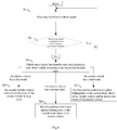
- a stability control method for a four-wheel drive electric vehicle includes the steps of: S1, detecting lateral acceleration signals; S2, judging whether the lateral acceleration is less than a preset acceleration threshold; S3, if the lateral acceleration is less than the acceleration threshold, returning to S2; S4, if the lateral acceleration is equal to or greater than the acceleration threshold, calculating a lateral load transfer ratio according to the lateral acceleration signals, and judging the state of the vehicle according to the lateral load transfer ratio to obtain at least one of a first braking force signal, a second braking force signal, a first logic signal and a second logic signal; S5, if the first logic signal is obtained, controlling the body of the electric vehicle to keep stable; S6, if the first braking force signal and the second logic signal are obtained, controlling a motor of the electric vehicle to apply braking force to an outside front wheel of the electric vehicle; and S7, if the second braking force signal and the second logic signal are obtained, controlling motors of the electric vehicle to apply braking force to the outside front wheel of the electric
- a four-wheel drive electric vehicle includes the stability control system for the four-wheel drive electric vehicle as mentioned in the above embodiment; motor controllers; and motors, wherein the motor controllers are connected with the motors and the stability control system respectively.
- the first stability control unit takes corresponding vehicle stable-keeping measures according to different states of the vehicle, particularly, when the vehicle has a rollover trend or risk, the first stability control unit can apply braking force to the outside front wheel of the vehicle via the motor, or apply braking force to the outside front wheel and the inside rear wheel of the vehicle, to keep the body stable.
- connection may be fixed connection, detachable connection, or integral connection; the “connection” may be mechanical connection, electrical connection, or mutual communication; the “connection” may be direct connection, or indirect connection via a medium, and the “connection” may be communication of interiors of two elements or interaction of two elements.
- connection may be fixed connection, detachable connection, or integral connection; the “connection” may be mechanical connection, electrical connection, or mutual communication; the “connection” may be direct connection, or indirect connection via a medium, and the “connection” may be communication of interiors of two elements or interaction of two elements.
- the existing common anti-rollover methods that can effectively improve the vehicle stability include a differential braking control technology, an active/semi-active suspension control technology, an active roll stabilizer technology, an active steering technology, an active brake, etc.
- each method has certain limitation, for example, a differential torsion braking control largely depends on the vertical load of the outside wheel, and when the wheel is going to leave the ground, only braking on the outside wheel is difficult in playing an effective role; the active suspension control technology and the active roll stabilizer can improve the rollover threshold value and suppress the rollover of the vehicle, but cannot meet the quick response requirement of anti-rollover; and a large-angle steering control may change the expected driving track of the vehicle, thus causing the problem of insufficient steering of the vehicle.
- independent four-wheel drive electric vehicles have come out. Because the independent four-wheel drive electric vehicle uses four motors to control the four wheels independently, and the motors response quickly (about 20 milliseconds), which has great advantages over the traditional hydraulic braking response time (about 200 milliseconds), how to use the independent four-wheel drive electric vehicle as the stability control means becomes a problem to be solved urgently.
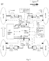
- an embodiment of the present application provides a stability control system 100 for a four-wheel drive electric vehicle (hereinafter referred to as a stability control system).
- the stability control system 100 is applicable to a four-wheel independently-drive electric vehicle.
- the electric vehicle may include four motor controllers 2, four motors 6 and a battery pack 4.
- Each motor controller 2 can separately control the corresponding motor 6.
- Each motor 6 is used for controlling a corresponding wheel 9 to run, e.g., producing driving force or braking force for the wheel 9.
- the motor 6 may be a wheel side motor, and the wheel side motor is connected to the corresponding wheel 9 via a transmission 7 and a drive shaft 8.
- the motor 6 may be a hub motor, in this case, the transmission 7 can be omited from the electric vehicle, which is beneficial to component layout of the vehicle.
- the battery pack 4 is connected with the motor controllers 2 via high voltage wires.
- the stability control system 100 includes a vehicle controller 1 and a signal detection sensor (not shown in the figure).
- the vehicle controller 1 is responsible for controlling the operation of the electric vehicle.
- the vehicle controller 1 includes a first stability control unit (not shown in the figure) and a second stability control unit (not shown in the figure).
- the first stability control unit, the second stability control unit, the signal detection sensor and the motor controllers 2 can communicate with each other via a CAN (Controller Area Network) bus of the vehicle.
- the second stability control unit may be an electronic body stability control unit of the vehicle.
- the battery pack 4 communicates with the vehicle controller 1.
- the signal detection sensor is used for detecting lateral acceleration signals.
- the signal detection sensor is further used for detecting wheel speed signals, vehicle speed signals, steering wheel angle signals, yaw angle speed signals and longitudinal acceleration signals.
- the signal detection sensor includes wheel speed sensors 11, a vehicle speed sensor 5A, a steering wheel angle sensor 3 and a yaw rate sensor 5.
- the wheel speed sensors 11 are used for detecting wheel speed signals.
- the vehicle speed sensor 5A is used for detecting vehicle speed signals.
- the steering wheel angle sensor 3 is used for detecting steering wheel angle signals.
- the yaw rate sensor 3 includes a longitudinal acceleration sensor, a lateral acceleration sensor and a yaw angle speed sensor.
- the yaw angle speed sensor is used for detecting yaw angle speed signals.
- the longitudinal acceleration sensor is used for detecting longitudinal acceleration signals.
- the lateral acceleration sensor is used for detecting lateral acceleration signals. It could be understood that the longitudinal acceleration sensor, the lateral acceleration sensor and the yaw angle speed sensor can be integrated together.
- the first stability control unit is used for judging whether the lateral acceleration is less than a preset acceleration threshold.
- the preset acceleration threshold can be set to 0.4g, wherein g is gravitational acceleration.
- the first stability control unit When judging that the lateral acceleration is less than the acceleration threshold, the first stability control unit is used for continuing to judge whether the lateral acceleration is less than the acceleration threshold.
- the first stability control unit is used for calculating a lateral load transfer ratio based on the lateral acceleration signals, and judging the state of the vehicle based on the lateral load transfer ratio to obtain at least one of a first braking force signal, a second braking force signal, a first logic signal and a second logic signal.
- the second stability control unit is used to, when obtaining the first logic signal, control the body of the electric vehicle to keep stable.
- the first stability control unit is further used to, when obtaining the first braking force signal and the second logic signal, control the motor of the electric vehicle via the motor controller of the electric vehicle to apply braking force to the outside front wheel of the electric vehicle.
- the first stability control unit is further used for, when obtaining the second braking force signal and the second logic signal, controlling the motors of the electric vehicle via the motor controllers of the electric vehicle to apply braking force to the outside front wheel of the electric vehicle and the inside rear wheel of the electric vehicle.
- the first stability control unit when obtaining the first logic signal, judges that the electric vehicle has a first trend. At the moment, the first stability control unit outputs the first logic signal to the second stability control unit.
- the second stability control unit is used for controlling the body of the electric vehicle to keep stable according to the first logic signal.
- the first stability control unit when obtaining the first braking force signal and the second logic signal, judges that the electric vehicle has a second trend. At the moment, the second stability control unit obtains the second logic signal, but does not output control.
- the first stability control unit when obtaining the second braking force signal and the second logic signal, judges that the electric vehicle has a third trend. At the moment, the second stability control unit obtains the second logic signal, but does not output control.
- the second stability control unit is used for controlling the body of the electric vehicle to keep stable.
- the first stability control unit is used for controlling the motor via the motor controller to apply braking force to the outside front wheel of the electric vehicle.
- the first stability control unit can generate a first braking force signal and send it to the motor controller, and the motor controller controls the motor according to the first braking force signal to apply braking force to the outside front wheel of the electric vehicle.
- the first stability control unit is used for controlling the motors via the motor controllers to apply braking force to the outside front wheel of the electric vehicle and the inside rear wheel of the electric vehicle.
- the first stability control unit can generate a second braking force signal and send it to the motor controllers, and the motor controllers control the motors according to the second braking force signal to apply braking force to the outside front wheel of the electric vehicle and the inside rear wheel of the electric vehicle.
- the outside wheels are right wheels 9, the inside wheels are left wheels 9, the outside front wheel is the upper right wheel 9, and the inside rear wheel is the lower left wheel 9.
- the outside wheels are left wheels 9, the inside wheels are right wheels 9, the outside front wheel is the upper left wheel 9, and the inside rear wheel is the lower right wheel 9.
- a first transfer ratio threshold, a second transfer ratio threshold and a third transfer ratio threshold are preset in the first stability control unit.
- the first transfer ratio threshold is greater than zero
- the second transfer ratio threshold is greater than the first transfer ratio threshold
- the third transfer ratio threshold is greater than the second transfer ratio threshold and less than 1.
- the first stability control unit obtains the first logic signal to determine that the electric vehicle has the first trend, e.g., the electric vehicle has a sideslip trend.
- the first stability control unit obtains the first braking force signal and the second logic signal to determine that the electric vehicle has the second trend, e.g., the electric vehicle has a rollover trend.
- the first stability control unit obtains the second braking force signal and the second logic signal to determine that the electric vehicle has the third trend, e.g., the electric vehicle has a rollover risk.
- LTR indicates the lateral load transfer ratio
- indicates the absolute value of the lateral load transfer ratio
- L1 indicates the first transfer ratio threshold
- L2 indicates the second transfer ratio threshold
- L3 indicates the third transfer ratio threshold.
- the second stability control unit controls the body of the electric vehicle to keep stable, e.g., the second stability control unit can brake the corresponding wheel 9 by controlling a brake execution mechanism (not shown in the figure) of the electric vehicle, thereby reducing sideslip so as to keep the body of the electric vehicle stable.
- the brake execution mechanism includes a brake master cylinder, a wheel cylinder, a brake disc and brake calipers.
- the brake disc is mounted on the hub and rotates together with the wheel 9.
- the brake pedal is pressed down, the push rod connected with the brake pedal and the brake master cylinder propels the brake master cylinder to produce hydraulic pressure.
- the hydraulic pressure produced by the brake master cylinder is transferred to the wheel cylinder, and the wheel cylinder applies pressure to the brake calipers to produce friction on the brake disc, thus braking the corresponding wheel 9.
- the second stability control unit controls the brake extraction mechanism to brake the corresponding wheel 9, e.g., when the electric vehicle has a sideslip trend while turning left, the second stability control unit is used for controlling the brake calipers corresponding to the inside rear wheel 9 to brake the inside rear wheel 9; and when the electric vehicle has a sideslip trend while turning right, the second stability control unit is used for controlling the brake calipers corresponding to the outside front wheel 9 to brake the outside front wheel 9.
- the first stability control unit executes a regenerative braking mode on the outside wheels by using the wheel side motors 6.
- An additional yaw torque is produced to reduce the yaw angle speed of the electric vehicle.
- the longitudinal speed of the electric vehicle is reduced with increase of the braking force.
- the tire force is generally saturated, and due to the nonlinearity of tires, it can be known from the adhesion ellipse of the electric vehicle that when the longitudinal force (braking force) is increased, the lateral force (braking force) of the ground applying to the wheels is correspondingly reduced, so that the lateral speed is also reduced.
- the lateral load transfer ratio is relatively large (generally caused by turning the steering wheel at a high speed or by lateral wind). At the moment, left and right wheel loads of the electric vehicle are seriously transferred. If the outside wheels provide corresponding yaw torques insufficiently, the wheel side motors 6 assist the inside wheels in regenerative braking while executing the regenerative braking on the outside wheels.
- the magnitudes of the regenerative braking torques of the inside and outside wheels are distributed in real time according to the status of the vehicle, and the distribution principle is as followed: at the road adhesion limit, the tire force is generally saturated, and due to the nonlinearity of tires, it can be known from the adhesion ellipse of the electric vehicle that when the longitudinal force (braking force) is increased, the lateral force is correspondingly reduced. However, the directions of yaw torques produced by longitudinal and lateral force changes of each wheel on the electric vehicle are different.
- Table 1 shows the statistical result of braking each wheel under certain turning angle, wherein “+” indicates that the yaw torque produced by the wheel is consistent with the desired moving direction of the vehicle, on the contrary, "-" indicates that the yaw torque produced by the wheel is opposite to the desired moving direction of the vehicle.
- the first stability control unit mainly executes braking interference to the outside front wheel or to the outside front wheel and the inside rear wheel, so that more reasonable and enough additional yaw torque is produced, the yaw angle speed and the lateral acceleration are reduced, the rollover posture of the body is corrected, and the vehicle quickly reaches a stable state.
- the additional yaw torque is the yaw torque produced by the outside front wheel, or the sum of the yaw torque produced by the outside front wheel and the yaw torque produced by the inside rear wheel.
- Table 1 shows the statistical result of braking each wheel under certain turning angle, wherein ⁇ M1, ⁇ M2, ⁇ M3 and ⁇ M4 are yaw torques produced by the four wheels to the vehicle when the wheels are braked.
- Table 1 Yaw torques Tire force Inside front wheel Outside front wheel Inside rear wheel Outside rear wheel Braking force increase + ⁇ M1 - ⁇ M2 + ⁇ M3 - ⁇ M4 Lateral force decrease - ⁇ M2 - ⁇ M2 + ⁇ M3 + ⁇ M4
- the stability control system 100 adopts the lateral load transfer ratio and the lateral acceleration as control objectives of electric vehicle stability.
- F L indicates vertical load borne by the left tires including the left front wheel and the left rear wheel, and
- F R indicates vertical load borne by the right tires including the right front wheel and the right rear wheel.
- the vertical loads of the left and right tires are transferred, that is, the value range of LTR is [-1,1].
- the lateral load transfer ratio is not easy to measure directly, so it can be indirectly measured by linear transformation on the LTR indicator based on the built vehicle model.
- the additional yaw torque can be obtained by comparing the actual lateral load transfer ratio LTR with the ideal lateral load transfer ratio LTRd, and then by calculating through the vehicle model and certain control algorithm.
- the additional yaw torque refers to a torque produced by applying additional braking force to one or more wheels based on an additional torque value M RSC calculated by the vehicle model in order to maintain the body stable and prevent rollover.
- the ideal lateral load transfer ratio namely the preset lateral load transfer ratio, is a rollover warning threshold artificially set in the first stability control unit, e.g., a value less than said first transfer ratio threshold.
- the additional yaw torque M RSC will be calculated by using a 2-DOF linear model and a sliding mode variable structure control algorithm as an example. It should be pointed out, the additional yaw torque M RSC can also be calculated via other known algorithm, e.g., "Vehicle Dynamics” of Tsinghua University Press, “Vehicle Dynamics and Control” of Mechanical Industry Press, doctoral thesis "Study on Vehicle Stability Control System Based on GPS” and the like all have mentioned this kind additional yaw torque algorithm.
- the sliding mode variable structure control algorithm is used relatively frequently, and many foreigner research the sliding mode variable structure control, e.g., the articles of Drakunow, et.al (2000), Gematsu and Gerdes (2002), Yi, et.al (2003), Yoshioka, et.al (1998), Slotine, Li (1991) and others introduce the sliding mode variable structure control algorithm in detail.
- This control method has the advantage of satisfying nonlinearity, time-varying property and uncertainty of the system.
- Fig. 3 which expresses a force condition when the vehicle turns left. It is assumed that the sprung mass of the vehicle is equal to the total mass, and the mass center positions of them are same, the following equations can be built to calculate the LTR.
- LTR is directly related to the lateral acceleration and the rolling angle, and the LTR decreases when the lateral acceleration or the rolling angle decreases.
- ⁇ d LTR d ⁇ t 2 ⁇ e ⁇ g h ⁇ v ⁇ y v xd
- a sliding mode controller is designed according to the 2-DOF vehicle model.
- the mass center rolling angle and the yaw angle speed should be simultaneously considered while a stability control target is selected.
- ⁇ is a constant.
- M RSC l f F yf cos ⁇ f + l r F yr + I Z ⁇ ⁇ d ⁇ ⁇ ⁇ ⁇ ⁇ ⁇ ⁇ d
- Stability factor K m L 2 l f k r ⁇ l r k f .
- l f and l r are vehicle parameters which are respectively the distance from the front and rear axle of the vehicle to the mass center of the vehicle.
- the lateral forces F yf and F yr of the front and rear wheels are calculated from the supplementary formulas below formula (4).
- ⁇ f is the front wheel turning angle which can be solved by detecting steering wheel angle signals via the steering wheel angle sensor and calculating from the ratio of the steering wheel angle to the front wheel turning angle.
- l z is the rotational inertia of the whole vehicle around the Z axis and is a constant value when the vehicle is manufactured.
- ⁇ d is an ideal yaw angle acceleration
- the (desired) ideal yaw angle speed ⁇ d LTR d ⁇ t 2 ⁇ e ⁇ g h ⁇ v ⁇ y v xd , namely formula (12)
- a yd LTR d ⁇ t 2 ⁇ e ⁇ g h and formula (11)
- a yd v ⁇ y + v xd ⁇ d
- ⁇ ⁇ d LTR d ⁇ t 2 ⁇ e ⁇ ⁇ g h ⁇ v ⁇ y v xd
- the denominator v xd is the ideal (desired) speed, which can be obtained by solving the wheel speeds of four wheels from the wheel speed signals detected by the wheel speed sensors 11 and selecting the average value of them.
- the stability control system 100 of this embodiment further includes four motor resolver sensors 10 which detect the rotational speed signals of the corresponding motors 6.
- the first stability control unit can also calculate the ideal vehicle speed according to the rotational speed signals of the motors.
- the wheel speed sensors and the resolver sensors can verify each other, which has the advantage that if one set of sensors fails, the other set of sensors can be used as the judgment basis of the first stability control unit, so that the accuracy of calculating the vehicle speed is improved.
- the ideal vehicle speed can also be solved by other algorithms.
- LTR d is the expected lateral load transfer ratio, and can be set on its own, e.g., set to 0.5.
- t wheel distance
- e is the distance between the mass center and the rolling center;
- ⁇ is a body rolling angle
- ⁇ ⁇ K ⁇ ⁇ m a ⁇ y e mg e
- K ⁇ is body rolling stiffness.
- the value of the lateral acceleration v ⁇ y of the body is numerical processed, so that the change rate v ⁇ y of the lateral acceleration of the body is calculated indirectly.
- ⁇ is a constant
- ⁇ is a mass center rolling angle and can be measured by a GPS device
- ⁇ is zero after derivation
- the formula of the derived ⁇ includes vehicle speed v x and longitudinal acceleration, wherein the vehicle speed v x can be acquired from the vehicle speed signals detected by the vehicle speed sensor 5A, and the longitudinal acceleration is acquired from the longitudinal acceleration signals detected by the longitudinal acceleration sensor.
- v x is the component of the whole vehicle speed in the X direction (longitudinal direction), and the component of the whole vehicle speed in the Y direction (horizontal direction) is very small relative to the vehicle speed in the X direction (longitudinal direction) and can be ignored, so the magnitude of the vehicle speed v x in the X direction (longitudinal direction) is substantially equal to the magnitude of the whole vehicle speed and can be detected by using the vehicle speed sensor 5A.
- the additional yaw torque M RSC can be calculated as long as steering wheel angles signals, wheel speed signals, vehicle speed signals, lateral acceleration signals, longitudinal acceleration signals and yaw angle speed signals are detected.
- the first stability control unit judges to apply braking force whether to the outside front wheel or to the outside front wheel and the inside rear wheel according to the magnitude of the lateral load transfer ratio LTR.
- LTR lateral load transfer ratio
- Table 2 Judgment basis Lateral acceleration Lateral load transfer ratio Vehicle state Wheel side motor control a y ⁇ a yd
- the preset acceleration threshold a yd is 0.4g
- the first transfer ratio threshold L1 is 0.5
- the second transfer ratio threshold L2 is 0.6
- the third transfer ratio threshold L3 is 0.9.
- the second stability control unit controls the body of the electric vehicle to keep stable, e.g., the second stability control unit can brake the corresponding wheel 9 by controlling the brake of the electric vehicle to reduce sideslip so as to keep the body of the vehicle stable, and the first stability control unit does not need to start the motor controllers 6 to control the motors 2, i.e., at the moment, the first stability control unit does not interfere with the wheel 9.
- the first stability control unit sends a first braking force signal to the motor controller 2 corresponding to the outside front wheel according to the magnitude of the braking force, and the motor controller 2 controls the motor 6 according to the first braking force signal to apply braking force to the outside front wheel.
- the vehicle produces certain yaw torque to correct the posture of the body, and is maintained to drive stably.
- the first stability control unit judges that the outside front wheel cannot provide corresponding ground braking force, wherein ⁇ is a road adhesion coefficient, during calculation, ⁇ is a constant value and can be designed according to the parameters before the vehicle leaves the factory, and F zo is the vertical load of the outside wheel.
- the first stability control unit enables the outside front wheel and the inside rear wheel to collectively form a reasonable yaw torque, the LTR is reduced to the desired LTR, and then the whole vehicle is maintained to drive stably.
- the first stability control unit sends a second braking force signal to the motor controller 2 corresponding to the outside front wheel and the motor controller 2 corresponding to the inside rear wheel, so that the motor controllers 2 control the corresponding motors 6 to apply braking force to the outside front wheel and the inside rear wheel.
- a stability control process when the vehicle urgently avoids an obstacle ahead or the steering wheel is turned suddenly while the vehicle is driving straight on a highway will be analyzed below in combination with an example.
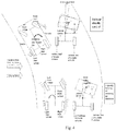
- Fig. 4 is a schematic diagram of a stability control process when the vehicle urgently avoids an obstacle ahead or the steering wheel is turned suddenly
- Fig. 5 is a principle diagram of stability control.
- the first stability control unit calculates the LTR in real time according to the signals of the steering wheel angle sensor 3, the yaw rate sensor 5, the vehicle speed sensor 5A and the wheel speed sensors 11 (or resolver sensors 10).
- the first stability control unit calculates the additional yaw torque M RSC in real time by using the vehicle model and the corresponding control algorithm, and applies braking force to the outside front wheel via the motor controller 2 and the wheel side motor 6 in the mode of regenerative braking, so that
- the first stability control unit calculates the additional yaw torque M RSC ' in real time by using the vehicle model and the corresponding control algorithm, and applies braking force to the outside front wheel and the inside rear wheel via the motor controllers 2 and the wheel side motors 6 in the mode of regenerative braking.
- the outside front wheel while regenerative braking, assists the inside rear wheel in regenerative braking to form a stronger differential torque, reduce the yaw angle speed and lateral acceleration, timely correct the rollover posture of the body and reduce the LTR value, so that the vehicle is maintained to run stable.
- the first stability control unit takes corresponding vehicle stable measures according to different states of the vehicle, particularly, when the vehicle has a rollover trend or risk, the first stability control unit can apply braking force to the outside front wheel of the vehicle, or apply braking force to the outside front wheel and the inside rear wheel of the vehicle, to keep the body stable.
- an embodiment of the present application provides a stability control method for a four-wheel drive electric vehicle (hereinafter referred to as a stability control method).
- the stability control method can be realized by the stability control system 100 of the above embodiment.
- the stability control method includes:
- the yaw rate sensor 5 of the signal detection sensor detects the lateral acceleration signals.
- the signal detection sensor includes wheel speed sensors, a vehicle speed sensor, a steering wheel angle sensor and the yaw rate sensor.
- the wheel speed sensors are used for detecting wheel speed signals.
- the vehicle speed sensor is used for detecting vehicle speed signals.
- the steering wheel angle sensor is used for detecting steering wheel angle sensor signals.
- the yaw rate sensor is further used for detecting yaw angle speed signals and longitudinal acceleration signals for subsequent calculation.
- the preset acceleration threshold is 0.4g in this embodiment.
- the first stability control unit calculates the lateral load transfer ratio as a basis for vehicle state judgment. Further, a first transfer ratio threshold, a second transfer ratio threshold and a third transfer ratio threshold are preset in the first stability control unit. The first transfer ratio threshold is greater than zero, the second transfer ratio threshold is greater than the first transfer ratio threshold, and the third transfer ratio threshold is greater than the second transfer ratio threshold and less than 1.
- the first stability control unit determines that the electric vehicle has a first trend, e.g., the electric vehicle has a sideslip trend.
- the first stability control unit judges that the electric vehicle has a second trend, e.g., the electric vehicle has a rollover trend.
- the first stability control unit judges that the electric vehicle has a third trend, e.g., the electric vehicle has a rollover risk.
- LTR indicates the lateral load transfer ratio
- indicates the absolute value of the lateral load transfer ratio
- L1 indicates the first transfer ratio threshold
- L2 indicates the second transfer ratio threshold
- L3 indicates the third transfer ratio threshold.
- the vehicle has a sideslip trend
- the second stability control unit for example, can brake the corresponding wheel 9 by controlling a brake (not shown in the figure) of the electric vehicle, to reduce sideslip so as to keep the body of the vehicle stable.
- the first stability control unit sends a first braking force signal to the motor controller 2 corresponding to the outside front wheel according to the magnitude of the braking force, and the motor controller 2 controls the motor 6 according to the first braking force signal to apply braking force to the outside front wheel.
- the vehicle produces certain yaw torque to correct the posture of the body, and is maintained to drive stably.
- the first stability control unit enables the outside front wheel and the inside rear wheel to collectively form a reasonable yaw torque, the LTR is reduced to the desired LTR, and then the whole vehicle is maintained to drive stably.
- the first stability control unit sends a second braking force signal to the motor controller 2 corresponding to the outside front wheel and the motor controller 2 corresponding to the inside rear wheel, and the motor controllers 2 control the corresponding motors 6 to apply braking force to the outside front wheel and the inside rear wheel.
- the first stability control unit takes corresponding vehicle stable measures according to different states of the vehicle, particularly, when the vehicle has a rollover trend or risk, the first stability control unit can apply braking force to the outside front wheel of the vehicle, or apply braking force to the outside front wheel and the inside rear wheel of the vehicle, to keep the body stable.
- An embodiment of the present application provides a four-wheel drive electric vehicle.
- the electric vehicle includes the above mentioned stability control system 100 for the four-wheel drive electric vehicle, motor controllers and motors, wherein the motor controllers are connected with the motors and the stability control system respectively.
- the first stability control unit of the electric vehicle takes corresponding vehicle stable measures according to different states of the vehicle, particularly, when the vehicle has a rollover trend or risk, the first stability control unit can apply braking force to the outside front wheel of the vehicle, or apply braking force to the outside front wheel and the inside rear wheel of the vehicle, to keep the body stable.
- first and second are merely for the sake of description, but cannot be understood as indicating or hinting the relative importance or implying the quantity of the indicated technical features.
- features defined with “first” and “second” may explicitly or implicitly include at least one of the features.
- “multiple” means at least two, e.g., two, three, etc., unless otherwise specified.
- any process or method described in the flow diagram or in other ways herein may be understood as a module, a fragment or a part expressing a code of an executable instruction including one or more steps for realizing specific logic functions or processes, and the scope of the preferred embodiments of the present application includes additional implementation, wherein the functions may not be executed according to the shown or discussed sequence, including substantially simultaneous manner or opposite sequence, which should be understood by those skilled in the art of the embodiments of the present application.
- Logics and/or steps expressed in the flow diagrams or described herein in other ways, for example, can be considered as a sequencing table of executable instructions for realizing logical functions, and can be embodied in any computer-readable medium, and used by an instruction execution system, device or equipment (e.g., a computer-based system, a processor-containing system, or other system that can extract an instruction from the instruction execution system, device or equipment and execute the instruction), or used in combination with the instruction execution system, device or equipment.
- the "computer-readable medium” may be any device that can include, store, communicate, propagate or transport programs used by the instruction execution system, device or equipment or used in combination with the instruction execution system, device or equipment.
- the computer-readable medium in more specific examples (a non-exhaustive list) includes: an electrical connection part (electronic device) having one or more wires, a portable computer disk cartridge (magnetic device), a random access memory (RAM), a read-only memory (ROM), an erasable programmable read-only memory (EPROM or flash memory), an optical fiber device, and a portable compact disc read-only memory (CDROM).
- the computer-readable medium even can be paper or other appropriate medium on which said programs are printed, for example, said programs can be obtained in an electronic mode by optically scanning paper or other medium and then editing, interpreting or processing it in other appropriate mode, and then the programs are stored in a computer memory.
- the functional units in the embodiments of the present application may be integrated in one processing module, or the units separately and physically exist, or two or more units are integrated in one module.
- the above-mentioned integrated module may be realized in the form of hardware or a software functional module.
- the integrated module is realized in the form of a software functional module and sold or used as an independent product, it can also be stored in a computer-readable storage medium.
- the aforementioned storage medium may be a read-only memory, a magnetic disc or an optical disc, etc.
Landscapes
- Engineering & Computer Science (AREA)
- Transportation (AREA)
- Mechanical Engineering (AREA)
- Automation & Control Theory (AREA)
- Power Engineering (AREA)
- Regulating Braking Force (AREA)
- Control Of Driving Devices And Active Controlling Of Vehicle (AREA)
- Electric Propulsion And Braking For Vehicles (AREA)
Applications Claiming Priority (2)
| Application Number | Priority Date | Filing Date | Title |
|---|---|---|---|
| CN201510487943.6A CN106427957B (zh) | 2015-08-11 | 2015-08-11 | 基于四轮驱动的电动汽车稳定控制系统及方法及电动汽车 |
| PCT/CN2016/094461 WO2017025042A1 (fr) | 2015-08-11 | 2016-08-10 | Système et procédé de contrôle de stabilité pour véhicule électrique à quatre roues motrices, et véhicule électrique |
Publications (3)
| Publication Number | Publication Date |
|---|---|
| EP3348444A1 true EP3348444A1 (fr) | 2018-07-18 |
| EP3348444A4 EP3348444A4 (fr) | 2018-10-17 |
| EP3348444B1 EP3348444B1 (fr) | 2021-04-28 |
Family
ID=57983869
Family Applications (1)
| Application Number | Title | Priority Date | Filing Date |
|---|---|---|---|
| EP16834666.6A Active EP3348444B1 (fr) | 2015-08-11 | 2016-08-10 | Système et procédé de contrôle de stabilité pour véhicule électrique à quatre roues motrices, et véhicule électrique |
Country Status (4)
| Country | Link |
|---|---|
| US (1) | US10543818B2 (fr) |
| EP (1) | EP3348444B1 (fr) |
| CN (1) | CN106427957B (fr) |
| WO (1) | WO2017025042A1 (fr) |
Families Citing this family (55)
| Publication number | Priority date | Publication date | Assignee | Title |
|---|---|---|---|---|
| DE102017200144B4 (de) * | 2016-01-22 | 2019-05-02 | Ford Global Technologies, Llc | Rückfallbetriebsmodus für ein Verfahren für das Betreiben eines Kraftfahrzeugs mit einem aktiven Querstabilisator und einer aktiven Lenkung |
| JP6823664B2 (ja) * | 2016-10-19 | 2021-02-03 | 川崎重工業株式会社 | タイヤ力推定装置およびタイヤ力推定方法 |
| CN106945652B (zh) * | 2017-03-13 | 2019-07-02 | 长安大学 | 一种电机驱动制动系统以及控制方法 |
| CN107089261B (zh) * | 2017-03-17 | 2023-07-18 | 江苏大学 | 一种集成eps的分布式驱动汽车转向控制系统及方法 |
| CN108928261B (zh) | 2017-05-26 | 2021-01-05 | 华为技术有限公司 | 一种驱动防滑控制方法及车辆 |
| CN107512256A (zh) * | 2017-08-18 | 2017-12-26 | 内蒙古大学 | 轿车辅助电动主动制动系统 |
| CN107806997A (zh) * | 2017-10-17 | 2018-03-16 | 北京新能源汽车股份有限公司 | 车辆制动测试试验台 |
| CN108099919B (zh) * | 2017-11-09 | 2019-01-29 | 珠海格力电器股份有限公司 | 车辆防侧翻预警方法、装置、存储介质及车辆 |
| CN108162955B (zh) * | 2017-12-28 | 2019-07-09 | 长沙理工大学 | 一种具有时滞辨识和补偿功能的车辆主动防侧翻控制系统 |
| CN108248583B (zh) * | 2018-02-09 | 2023-05-12 | 南京航空航天大学 | 一种汽车电子稳定控制系统及其分层控制方法 |
| EP3536568B1 (fr) * | 2018-03-06 | 2021-01-13 | Volvo Car Corporation | Procédé et système permettant une meilleure réponse de lacet pour un véhicule |
| CN108528274B (zh) * | 2018-05-08 | 2021-05-14 | 昆明理工大学 | 一种基于树莓派和向心加速度计算汽车电子差速的方法 |
| CN109050659B (zh) * | 2018-07-06 | 2020-09-18 | 长春工业大学 | 一种基于时变动力学模型的四轮转向汽车稳定性控制方法 |
| CN109050658B (zh) * | 2018-07-06 | 2020-09-18 | 长春工业大学 | 基于模型预测控制的汽车主动前轮转向自适应调节方法 |
| CN108944866B (zh) * | 2018-07-06 | 2021-06-01 | 长春工业大学 | 一种改善转向与制动协同控制的自适应模型预测控制算法 |
| JP6983127B2 (ja) * | 2018-08-09 | 2021-12-17 | 本田技研工業株式会社 | 駆動力制御装置 |
| CN109305011B (zh) * | 2018-11-01 | 2021-08-17 | 珠海格力电器股份有限公司 | 一种车辆防侧翻的控制方法、装置、存储介质及车辆 |
| CN109543256B (zh) * | 2018-11-08 | 2023-01-20 | 北京电子工程总体研究所 | 一种过载响应时间计算方法和系统 |
| CN109733382B (zh) * | 2018-12-19 | 2020-07-07 | 南京航空航天大学 | 一种基于模型预测控制的汽车防侧翻方法 |
| CN109747435A (zh) * | 2019-02-25 | 2019-05-14 | 吉利汽车研究院(宁波)有限公司 | 车辆稳定控制系统、方法及电动汽车 |
| CN110194213B (zh) * | 2019-05-09 | 2023-11-24 | 上海工程技术大学 | 汽车防侧翻系统 |
| CN110065488B (zh) * | 2019-05-15 | 2024-02-02 | 大连华锐重工焦炉车辆设备有限公司 | 一种重型agv框架运输车智能控制系统及控制方法 |
| CN111027132B (zh) * | 2019-08-08 | 2022-08-23 | 中国第一汽车股份有限公司 | 车辆侧倾控制方法、装置、设备和存储介质 |
| CN110466361B (zh) * | 2019-08-14 | 2021-06-01 | 东风汽车集团有限公司 | 两轮轮毂电机驱动纯电动汽车整车控制器及控制方法 |
| CN110884363B (zh) * | 2019-12-09 | 2022-08-23 | 吉林大学 | 一种应用于汽车电驱动桥的驱动防滑控制方法 |
| CN111645684B (zh) * | 2020-04-29 | 2021-09-17 | 北汽福田汽车股份有限公司 | 车辆制动能量回收方法、装置、存储介质及车辆 |
| CN111546907B (zh) * | 2020-05-22 | 2022-04-08 | 西南交通大学 | 一种四轮转向轮毂电机驱动车辆的轮速分配方法 |
| CN112477853B (zh) * | 2020-11-11 | 2022-06-28 | 南京航空航天大学 | 一种装备非充气车轮的车辆纵-垂集成控制系统及方法 |
| CN112706756B (zh) * | 2020-11-25 | 2022-03-29 | 东风越野车有限公司 | 轮毂电机驱动越野车横摆稳定性控制方法 |
| CN112406854B (zh) * | 2020-11-25 | 2022-05-10 | 东风越野车有限公司 | 轮毂电机驱动越野车侧倾稳定性控制方法 |
| CN112660108B (zh) * | 2020-12-25 | 2022-11-08 | 浙江吉利控股集团有限公司 | 一种四驱扭矩预控方法及装置 |
| JP7150001B2 (ja) | 2020-12-28 | 2022-10-07 | 本田技研工業株式会社 | 車両制御装置 |
| CN112947183B (zh) * | 2021-02-05 | 2022-10-18 | 上海擎度汽车科技有限公司 | 一种车身稳定性标定系统 |
| CN113147413B (zh) * | 2021-05-20 | 2022-09-20 | 武汉理工大学 | 一种轮毂电机差动转向车辆能量回收的方法、装置和系统 |
| CN113246681B (zh) * | 2021-06-12 | 2022-11-25 | 北华大学 | 基于空气悬架的机场摆渡车转弯姿态调整方法 |
| CN113320524B (zh) * | 2021-06-15 | 2022-05-17 | 广汽本田汽车有限公司 | 汽车的控制方法、汽车、运行控制装置及存储介质 |
| CN113401114B (zh) * | 2021-07-26 | 2022-03-25 | 吉林大学 | 一种半挂汽车横摆稳定性控制方法 |
| US12221091B2 (en) | 2021-08-13 | 2025-02-11 | Warn Automotive, Llc | EV disconnect control |
| CN113635889A (zh) * | 2021-08-13 | 2021-11-12 | 的卢技术有限公司 | 基于四轮独立驱动电动汽车的车身稳定控制方法和系统 |
| CN113682282A (zh) * | 2021-09-10 | 2021-11-23 | 中国第一汽车股份有限公司 | 一种车辆稳定性控制方法、系统、车辆和存储介质 |
| CN113665374B (zh) * | 2021-09-28 | 2024-06-18 | 潍柴动力股份有限公司 | 车辆速度的控制方法、装置、设备及存储介质 |
| JP7756532B2 (ja) * | 2021-10-01 | 2025-10-20 | 三菱重工業株式会社 | 走行制御装置、車両、走行制御方法及びプログラム |
| CN115257920B (zh) * | 2022-04-25 | 2024-05-03 | 长城汽车股份有限公司 | 一种用于车辆辅助转向控制的方法和装置 |
| US11607952B1 (en) * | 2022-05-04 | 2023-03-21 | Dimaag-Ai, Inc. | Methods and systems for controlling differential wheel speeds of multi- independent-wheel drive vehicles |
| CN117125133A (zh) * | 2022-05-20 | 2023-11-28 | 比亚迪股份有限公司 | 后驱车辆转向控制方法、系统、控制器及车辆 |
| CN115675634B (zh) * | 2022-11-16 | 2025-02-25 | 长城汽车股份有限公司 | 前后轮的控制方法、系统、电子设备、存储介质及车辆 |
| CN116176534B (zh) * | 2023-02-09 | 2025-08-05 | 南京市德赛西威汽车电子有限公司 | 一种电动车防侧滑控制方法及系统 |
| CN116039587B (zh) * | 2023-03-30 | 2023-06-20 | 小米汽车科技有限公司 | 制动控制方法、装置、系统、车辆、介质及芯片 |
| US12559073B2 (en) * | 2023-05-15 | 2026-02-24 | Hyundai Motor Company | Self-calibrating wheel speed signals for adjusting brake and chassis controls |
| DE102024114617A1 (de) * | 2023-06-27 | 2025-01-02 | Scania Cv Ab | Verfahren und Steueranordnung zum Steuern eines Bremssystems in einem Fahrzeug |
| CN117207783A (zh) * | 2023-09-12 | 2023-12-12 | 上海安沛动力科技有限公司 | 电驱动系统的效率提升方法 |
| CN119370188A (zh) * | 2024-11-18 | 2025-01-28 | 浙江吉利控股集团有限公司 | 车辆转弯控制方法、装置、车辆、计算机设备及存储介质 |
| CN119459620B (zh) * | 2025-01-16 | 2025-05-13 | 上海同驭汽车科技有限公司 | 一种冗余车辆动态控制方法、控制器及电子液压制动系统 |
| CN120422823B (zh) * | 2025-07-10 | 2025-10-10 | 万向钱潮股份公司 | 一种电子机械制动系统扭矩控制方法、设备、车辆、介质 |
| KR102935059B1 (ko) | 2025-11-06 | 2026-03-09 | 에스앤씨 주식회사 | 이중화된 차량용 속도센서의 폴백 제어 장치 |
Family Cites Families (20)
| Publication number | Priority date | Publication date | Assignee | Title |
|---|---|---|---|---|
| JP2572860B2 (ja) | 1989-10-27 | 1997-01-16 | 日産自動車株式会社 | 車両の旋回挙動制御装置 |
| KR100684033B1 (ko) | 2002-02-23 | 2007-02-16 | 주식회사 만도 | 차량의 주행 안정성 제어방법 |
| JP4380253B2 (ja) * | 2003-07-23 | 2009-12-09 | 株式会社アドヴィックス | 車両の運動制御装置 |
| JP4380307B2 (ja) | 2003-11-26 | 2009-12-09 | 日産自動車株式会社 | 自動制動制御装置 |
| JP4586962B2 (ja) | 2004-04-20 | 2010-11-24 | トヨタ自動車株式会社 | 車両の姿勢制御装置 |
| US8565993B2 (en) * | 2005-10-11 | 2013-10-22 | Volvo Car Corporation | Enhanced yaw stability control to mitigate a vehicle's abnormal yaw motion due to a disturbance force applied to vehicle body |
| JP4730065B2 (ja) | 2005-11-14 | 2011-07-20 | 株式会社アドヴィックス | 車両の運動制御装置 |
| JP5095953B2 (ja) * | 2006-05-08 | 2012-12-12 | 本田技研工業株式会社 | 四輪駆動車両の走行制御装置 |
| US7970512B2 (en) * | 2006-08-30 | 2011-06-28 | Ford Global Technologies | Integrated control system for stability control of yaw, roll and lateral motion of a driving vehicle using an integrated sensing system with pitch information |
| US8712639B2 (en) * | 2006-08-30 | 2014-04-29 | Ford Global Technologies | Integrated control system for stability control of yaw, roll and lateral motion of a driving vehicle using an integrated sensing system to determine longitudinal velocity |
| JP4412400B2 (ja) | 2007-12-14 | 2010-02-10 | トヨタ自動車株式会社 | 車両用挙動制御装置 |
| US8453770B2 (en) * | 2009-01-29 | 2013-06-04 | Tesla Motors, Inc. | Dual motor drive and control system for an electric vehicle |
| CN102205781B (zh) * | 2010-03-31 | 2015-04-01 | 日立汽车系统株式会社 | 悬架控制装置及车辆控制装置 |
| US8521349B2 (en) * | 2010-06-10 | 2013-08-27 | Ford Global Technologies | Vehicle steerability and stability control via independent wheel torque control |
| US9199639B2 (en) | 2010-09-28 | 2015-12-01 | Hitachi Automotive Systems, Ltd. | Motion control system of vehicle |
| TWI471239B (zh) * | 2011-10-21 | 2015-02-01 | Automotive Res & Testing Ct | Vehicle Yaw Stability Control Method and Its System |
| CN103182956B (zh) * | 2011-12-28 | 2015-09-02 | 比亚迪股份有限公司 | 电动四轮驱动车辆稳定控制方法和控制系统 |
| US9415657B2 (en) * | 2012-01-25 | 2016-08-16 | Nissan Motor Co., Ltd. | Vehicle control device and vehicle control method |
| US9222854B2 (en) * | 2013-03-12 | 2015-12-29 | The Goodyear Tire & Rubber Company | Vehicle dynamic load estimation system and method |
| CN104773169B (zh) * | 2015-04-28 | 2017-05-24 | 吉林大学 | 一种基于轮胎侧偏角的车辆横摆稳定集成控制方法 |
-
2015
- 2015-08-11 CN CN201510487943.6A patent/CN106427957B/zh active Active
-
2016
- 2016-08-10 US US15/751,763 patent/US10543818B2/en active Active
- 2016-08-10 EP EP16834666.6A patent/EP3348444B1/fr active Active
- 2016-08-10 WO PCT/CN2016/094461 patent/WO2017025042A1/fr not_active Ceased
Also Published As
| Publication number | Publication date |
|---|---|
| US10543818B2 (en) | 2020-01-28 |
| CN106427957B (zh) | 2019-03-29 |
| WO2017025042A1 (fr) | 2017-02-16 |
| CN106427957A (zh) | 2017-02-22 |
| EP3348444A4 (fr) | 2018-10-17 |
| EP3348444B1 (fr) | 2021-04-28 |
| US20180236989A1 (en) | 2018-08-23 |
Similar Documents
| Publication | Publication Date | Title |
|---|---|---|
| EP3348444B1 (fr) | Système et procédé de contrôle de stabilité pour véhicule électrique à quatre roues motrices, et véhicule électrique | |
| US10967870B2 (en) | Hill descent system for vehicle and control method thereof | |
| CN108248454B (zh) | 车身稳定控制系统、方法及汽车 | |
| CN106467111B (zh) | 车身稳定控制方法、系统及汽车 | |
| Ni et al. | Dynamics control of autonomous vehicle at driving limits and experiment on an autonomous formula racing car | |
| CN106608201B (zh) | 电动车辆及其主动安全控制系统和方法 | |
| EP3057848B1 (fr) | Procédé de commande de comportement de véhicule | |
| CN106945670B (zh) | 基于驾驶员输入预测的汽车防侧翻系统及控制方法 | |
| US8170767B2 (en) | Vehicle stability control system and method | |
| JP2010162911A (ja) | 車両の運動制御装置 | |
| CN103171623B (zh) | 车辆横摆稳定控制方法及其系统 | |
| CN102282052A (zh) | 车辆状态估计装置 | |
| JP5958643B2 (ja) | 車両の基準運動状態量の演算方法 | |
| CN110126808B (zh) | 一种爆胎状态下分布式驱动电动汽车的控制方法及系统 | |
| EP4360921A2 (fr) | Réglage de système de dynamique de marche de véhicule | |
| KR20210008816A (ko) | 차량용 외란 대처 시스템 | |
| JP2010531262A5 (fr) | ||
| JP3705077B2 (ja) | 車輌の運動制御装置 | |
| JP5993843B2 (ja) | 車両の運動制御装置 | |
| Zhao et al. | Traction control system of electric vehicle with 4 in-wheel motors using lyapunov stability analysis algorithm | |
| EP2818371A1 (fr) | Système de commande de pédale pour un véhicule | |
| CN121019542A (zh) | 车辆转向控制方法、设备及存储介质 | |
| EP2813415A1 (fr) | Système de commande de volant pour un véhicule | |
| Bahnasy et al. | Investigation of Different Parameter Based Control Strategies for Active Independent Front Steering (AIFS) System | |
| DE102006009680A1 (de) | Fahrdynamik-Regelsystem eines zweispurigen Fahrzeugs |
Legal Events
| Date | Code | Title | Description |
|---|---|---|---|
| STAA | Information on the status of an ep patent application or granted ep patent |
Free format text: STATUS: THE INTERNATIONAL PUBLICATION HAS BEEN MADE |
|
| PUAI | Public reference made under article 153(3) epc to a published international application that has entered the european phase |
Free format text: ORIGINAL CODE: 0009012 |
|
| STAA | Information on the status of an ep patent application or granted ep patent |
Free format text: STATUS: REQUEST FOR EXAMINATION WAS MADE |
|
| 17P | Request for examination filed |
Effective date: 20180308 |
|
| AK | Designated contracting states |
Kind code of ref document: A1 Designated state(s): AL AT BE BG CH CY CZ DE DK EE ES FI FR GB GR HR HU IE IS IT LI LT LU LV MC MK MT NL NO PL PT RO RS SE SI SK SM TR |
|
| AX | Request for extension of the european patent |
Extension state: BA ME |
|
| A4 | Supplementary search report drawn up and despatched |
Effective date: 20180919 |
|
| RIC1 | Information provided on ipc code assigned before grant |
Ipc: B60T 8/1755 20060101AFI20180913BHEP Ipc: B60W 30/04 20060101ALI20180913BHEP Ipc: B60T 8/1769 20060101ALI20180913BHEP |
|
| DAV | Request for validation of the european patent (deleted) | ||
| DAX | Request for extension of the european patent (deleted) | ||
| RIC1 | Information provided on ipc code assigned before grant |
Ipc: B60W 30/04 20060101ALI20201014BHEP Ipc: B60T 8/1755 20060101AFI20201014BHEP Ipc: B60T 8/1769 20060101ALI20201014BHEP |
|
| GRAP | Despatch of communication of intention to grant a patent |
Free format text: ORIGINAL CODE: EPIDOSNIGR1 |
|
| STAA | Information on the status of an ep patent application or granted ep patent |
Free format text: STATUS: GRANT OF PATENT IS INTENDED |
|
| INTG | Intention to grant announced |
Effective date: 20201123 |
|
| GRAS | Grant fee paid |
Free format text: ORIGINAL CODE: EPIDOSNIGR3 |
|
| GRAA | (expected) grant |
Free format text: ORIGINAL CODE: 0009210 |
|
| STAA | Information on the status of an ep patent application or granted ep patent |
Free format text: STATUS: THE PATENT HAS BEEN GRANTED |
|
| AK | Designated contracting states |
Kind code of ref document: B1 Designated state(s): AL AT BE BG CH CY CZ DE DK EE ES FI FR GB GR HR HU IE IS IT LI LT LU LV MC MK MT NL NO PL PT RO RS SE SI SK SM TR |
|
| REG | Reference to a national code |
Ref country code: GB Ref legal event code: FG4D |
|
| REG | Reference to a national code |
Ref country code: CH Ref legal event code: NV Representative=s name: DENNEMEYER AG, CH Ref country code: CH Ref legal event code: EP |
|
| REG | Reference to a national code |
Ref country code: AT Ref legal event code: REF Ref document number: 1386745 Country of ref document: AT Kind code of ref document: T Effective date: 20210515 |
|
| REG | Reference to a national code |
Ref country code: DE Ref legal event code: R096 Ref document number: 602016057055 Country of ref document: DE |
|
| REG | Reference to a national code |
Ref country code: IE Ref legal event code: FG4D |
|
| REG | Reference to a national code |
Ref country code: NL Ref legal event code: FP |
|
| REG | Reference to a national code |
Ref country code: LT Ref legal event code: MG9D |
|
| REG | Reference to a national code |
Ref country code: AT Ref legal event code: MK05 Ref document number: 1386745 Country of ref document: AT Kind code of ref document: T Effective date: 20210428 |
|
| PG25 | Lapsed in a contracting state [announced via postgrant information from national office to epo] |
Ref country code: FI Free format text: LAPSE BECAUSE OF FAILURE TO SUBMIT A TRANSLATION OF THE DESCRIPTION OR TO PAY THE FEE WITHIN THE PRESCRIBED TIME-LIMIT Effective date: 20210428 Ref country code: LT Free format text: LAPSE BECAUSE OF FAILURE TO SUBMIT A TRANSLATION OF THE DESCRIPTION OR TO PAY THE FEE WITHIN THE PRESCRIBED TIME-LIMIT Effective date: 20210428 Ref country code: HR Free format text: LAPSE BECAUSE OF FAILURE TO SUBMIT A TRANSLATION OF THE DESCRIPTION OR TO PAY THE FEE WITHIN THE PRESCRIBED TIME-LIMIT Effective date: 20210428 Ref country code: AT Free format text: LAPSE BECAUSE OF FAILURE TO SUBMIT A TRANSLATION OF THE DESCRIPTION OR TO PAY THE FEE WITHIN THE PRESCRIBED TIME-LIMIT Effective date: 20210428 Ref country code: BG Free format text: LAPSE BECAUSE OF FAILURE TO SUBMIT A TRANSLATION OF THE DESCRIPTION OR TO PAY THE FEE WITHIN THE PRESCRIBED TIME-LIMIT Effective date: 20210728 |
|
| PG25 | Lapsed in a contracting state [announced via postgrant information from national office to epo] |
Ref country code: PL Free format text: LAPSE BECAUSE OF FAILURE TO SUBMIT A TRANSLATION OF THE DESCRIPTION OR TO PAY THE FEE WITHIN THE PRESCRIBED TIME-LIMIT Effective date: 20210428 Ref country code: PT Free format text: LAPSE BECAUSE OF FAILURE TO SUBMIT A TRANSLATION OF THE DESCRIPTION OR TO PAY THE FEE WITHIN THE PRESCRIBED TIME-LIMIT Effective date: 20210830 Ref country code: NO Free format text: LAPSE BECAUSE OF FAILURE TO SUBMIT A TRANSLATION OF THE DESCRIPTION OR TO PAY THE FEE WITHIN THE PRESCRIBED TIME-LIMIT Effective date: 20210728 Ref country code: RS Free format text: LAPSE BECAUSE OF FAILURE TO SUBMIT A TRANSLATION OF THE DESCRIPTION OR TO PAY THE FEE WITHIN THE PRESCRIBED TIME-LIMIT Effective date: 20210428 Ref country code: SE Free format text: LAPSE BECAUSE OF FAILURE TO SUBMIT A TRANSLATION OF THE DESCRIPTION OR TO PAY THE FEE WITHIN THE PRESCRIBED TIME-LIMIT Effective date: 20210428 Ref country code: GR Free format text: LAPSE BECAUSE OF FAILURE TO SUBMIT A TRANSLATION OF THE DESCRIPTION OR TO PAY THE FEE WITHIN THE PRESCRIBED TIME-LIMIT Effective date: 20210729 Ref country code: LV Free format text: LAPSE BECAUSE OF FAILURE TO SUBMIT A TRANSLATION OF THE DESCRIPTION OR TO PAY THE FEE WITHIN THE PRESCRIBED TIME-LIMIT Effective date: 20210428 Ref country code: IS Free format text: LAPSE BECAUSE OF FAILURE TO SUBMIT A TRANSLATION OF THE DESCRIPTION OR TO PAY THE FEE WITHIN THE PRESCRIBED TIME-LIMIT Effective date: 20210828 |
|
| PG25 | Lapsed in a contracting state [announced via postgrant information from national office to epo] |
Ref country code: SM Free format text: LAPSE BECAUSE OF FAILURE TO SUBMIT A TRANSLATION OF THE DESCRIPTION OR TO PAY THE FEE WITHIN THE PRESCRIBED TIME-LIMIT Effective date: 20210428 Ref country code: SK Free format text: LAPSE BECAUSE OF FAILURE TO SUBMIT A TRANSLATION OF THE DESCRIPTION OR TO PAY THE FEE WITHIN THE PRESCRIBED TIME-LIMIT Effective date: 20210428 Ref country code: CZ Free format text: LAPSE BECAUSE OF FAILURE TO SUBMIT A TRANSLATION OF THE DESCRIPTION OR TO PAY THE FEE WITHIN THE PRESCRIBED TIME-LIMIT Effective date: 20210428 Ref country code: EE Free format text: LAPSE BECAUSE OF FAILURE TO SUBMIT A TRANSLATION OF THE DESCRIPTION OR TO PAY THE FEE WITHIN THE PRESCRIBED TIME-LIMIT Effective date: 20210428 Ref country code: DK Free format text: LAPSE BECAUSE OF FAILURE TO SUBMIT A TRANSLATION OF THE DESCRIPTION OR TO PAY THE FEE WITHIN THE PRESCRIBED TIME-LIMIT Effective date: 20210428 Ref country code: RO Free format text: LAPSE BECAUSE OF FAILURE TO SUBMIT A TRANSLATION OF THE DESCRIPTION OR TO PAY THE FEE WITHIN THE PRESCRIBED TIME-LIMIT Effective date: 20210428 Ref country code: ES Free format text: LAPSE BECAUSE OF FAILURE TO SUBMIT A TRANSLATION OF THE DESCRIPTION OR TO PAY THE FEE WITHIN THE PRESCRIBED TIME-LIMIT Effective date: 20210428 |
|
| REG | Reference to a national code |
Ref country code: DE Ref legal event code: R097 Ref document number: 602016057055 Country of ref document: DE |
|
| PLBE | No opposition filed within time limit |
Free format text: ORIGINAL CODE: 0009261 |
|
| STAA | Information on the status of an ep patent application or granted ep patent |
Free format text: STATUS: NO OPPOSITION FILED WITHIN TIME LIMIT |
|
| PG25 | Lapsed in a contracting state [announced via postgrant information from national office to epo] |
Ref country code: MC Free format text: LAPSE BECAUSE OF FAILURE TO SUBMIT A TRANSLATION OF THE DESCRIPTION OR TO PAY THE FEE WITHIN THE PRESCRIBED TIME-LIMIT Effective date: 20210428 |
|
| 26N | No opposition filed |
Effective date: 20220131 |
|
| REG | Reference to a national code |
Ref country code: BE Ref legal event code: MM Effective date: 20210831 |
|
| PG25 | Lapsed in a contracting state [announced via postgrant information from national office to epo] |
Ref country code: IS Free format text: LAPSE BECAUSE OF FAILURE TO SUBMIT A TRANSLATION OF THE DESCRIPTION OR TO PAY THE FEE WITHIN THE PRESCRIBED TIME-LIMIT Effective date: 20210828 Ref country code: LU Free format text: LAPSE BECAUSE OF NON-PAYMENT OF DUE FEES Effective date: 20210810 Ref country code: AL Free format text: LAPSE BECAUSE OF FAILURE TO SUBMIT A TRANSLATION OF THE DESCRIPTION OR TO PAY THE FEE WITHIN THE PRESCRIBED TIME-LIMIT Effective date: 20210428 |
|
| PG25 | Lapsed in a contracting state [announced via postgrant information from national office to epo] |
Ref country code: IT Free format text: LAPSE BECAUSE OF FAILURE TO SUBMIT A TRANSLATION OF THE DESCRIPTION OR TO PAY THE FEE WITHIN THE PRESCRIBED TIME-LIMIT Effective date: 20210428 Ref country code: IE Free format text: LAPSE BECAUSE OF NON-PAYMENT OF DUE FEES Effective date: 20210810 Ref country code: BE Free format text: LAPSE BECAUSE OF NON-PAYMENT OF DUE FEES Effective date: 20210831 |
|
| PG25 | Lapsed in a contracting state [announced via postgrant information from national office to epo] |
Ref country code: HU Free format text: LAPSE BECAUSE OF FAILURE TO SUBMIT A TRANSLATION OF THE DESCRIPTION OR TO PAY THE FEE WITHIN THE PRESCRIBED TIME-LIMIT; INVALID AB INITIO Effective date: 20160810 |
|
| PG25 | Lapsed in a contracting state [announced via postgrant information from national office to epo] |
Ref country code: CY Free format text: LAPSE BECAUSE OF FAILURE TO SUBMIT A TRANSLATION OF THE DESCRIPTION OR TO PAY THE FEE WITHIN THE PRESCRIBED TIME-LIMIT Effective date: 20210428 |
|
| P01 | Opt-out of the competence of the unified patent court (upc) registered |
Effective date: 20230527 |
|
| PG25 | Lapsed in a contracting state [announced via postgrant information from national office to epo] |
Ref country code: MK Free format text: LAPSE BECAUSE OF FAILURE TO SUBMIT A TRANSLATION OF THE DESCRIPTION OR TO PAY THE FEE WITHIN THE PRESCRIBED TIME-LIMIT Effective date: 20210428 |
|
| PG25 | Lapsed in a contracting state [announced via postgrant information from national office to epo] |
Ref country code: MT Free format text: LAPSE BECAUSE OF FAILURE TO SUBMIT A TRANSLATION OF THE DESCRIPTION OR TO PAY THE FEE WITHIN THE PRESCRIBED TIME-LIMIT Effective date: 20210428 |
|
| PGFP | Annual fee paid to national office [announced via postgrant information from national office to epo] |
Ref country code: NL Payment date: 20250821 Year of fee payment: 10 |
|
| PGFP | Annual fee paid to national office [announced via postgrant information from national office to epo] |
Ref country code: DE Payment date: 20250820 Year of fee payment: 10 |
|
| PGFP | Annual fee paid to national office [announced via postgrant information from national office to epo] |
Ref country code: GB Payment date: 20250821 Year of fee payment: 10 |
|
| PGFP | Annual fee paid to national office [announced via postgrant information from national office to epo] |
Ref country code: FR Payment date: 20250828 Year of fee payment: 10 |
|
| PGFP | Annual fee paid to national office [announced via postgrant information from national office to epo] |
Ref country code: CH Payment date: 20250901 Year of fee payment: 10 |
|
| PG25 | Lapsed in a contracting state [announced via postgrant information from national office to epo] |
Ref country code: TR Free format text: LAPSE BECAUSE OF FAILURE TO SUBMIT A TRANSLATION OF THE DESCRIPTION OR TO PAY THE FEE WITHIN THE PRESCRIBED TIME-LIMIT Effective date: 20210428 |