EP3348501B1 - Dispositif de préhension de produit - Google Patents
Dispositif de préhension de produit Download PDFInfo
- Publication number
- EP3348501B1 EP3348501B1 EP18150660.1A EP18150660A EP3348501B1 EP 3348501 B1 EP3348501 B1 EP 3348501B1 EP 18150660 A EP18150660 A EP 18150660A EP 3348501 B1 EP3348501 B1 EP 3348501B1
- Authority
- EP
- European Patent Office
- Prior art keywords
- pick
- part portion
- product
- offset
- accordance
- Prior art date
- Legal status (The legal status is an assumption and is not a legal conclusion. Google has not performed a legal analysis and makes no representation as to the accuracy of the status listed.)
- Active
Links
Images



Classifications
-
- B—PERFORMING OPERATIONS; TRANSPORTING
- B65—CONVEYING; PACKING; STORING; HANDLING THIN OR FILAMENTARY MATERIAL
- B65G—TRANSPORT OR STORAGE DEVICES, e.g. CONVEYORS FOR LOADING OR TIPPING, SHOP CONVEYOR SYSTEMS OR PNEUMATIC TUBE CONVEYORS
- B65G47/00—Article or material-handling devices associated with conveyors; Methods employing such devices
- B65G47/74—Feeding, transfer, or discharging devices of particular kinds or types
- B65G47/90—Devices for picking-up and depositing articles or materials
-
- A—HUMAN NECESSITIES
- A22—BUTCHERING; MEAT TREATMENT; PROCESSING POULTRY OR FISH
- A22C—PROCESSING MEAT, POULTRY, OR FISH
- A22C17/00—Other devices for processing meat or bones
- A22C17/0093—Handling, transporting or packaging pieces of meat
-
- B—PERFORMING OPERATIONS; TRANSPORTING
- B25—HAND TOOLS; PORTABLE POWER-DRIVEN TOOLS; MANIPULATORS
- B25J—MANIPULATORS; CHAMBERS PROVIDED WITH MANIPULATION DEVICES
- B25J11/00—Manipulators not otherwise provided for
- B25J11/0045—Manipulators used in the food industry
-
- B—PERFORMING OPERATIONS; TRANSPORTING
- B25—HAND TOOLS; PORTABLE POWER-DRIVEN TOOLS; MANIPULATORS
- B25J—MANIPULATORS; CHAMBERS PROVIDED WITH MANIPULATION DEVICES
- B25J15/00—Gripping heads and other end effectors
- B25J15/0014—Gripping heads and other end effectors having fork, comb or plate shaped means for engaging the lower surface on a object to be transported
-
- B—PERFORMING OPERATIONS; TRANSPORTING
- B65—CONVEYING; PACKING; STORING; HANDLING THIN OR FILAMENTARY MATERIAL
- B65B—MACHINES, APPARATUS OR DEVICES FOR, OR METHODS OF, PACKAGING ARTICLES OR MATERIALS; UNPACKING
- B65B25/00—Packaging other articles presenting special problems
- B65B25/06—Packaging slices or specially-shaped pieces of meat, cheese, or other plastic or tacky products
- B65B25/065—Packaging slices or specially-shaped pieces of meat, cheese, or other plastic or tacky products of meat
-
- B—PERFORMING OPERATIONS; TRANSPORTING
- B65—CONVEYING; PACKING; STORING; HANDLING THIN OR FILAMENTARY MATERIAL
- B65B—MACHINES, APPARATUS OR DEVICES FOR, OR METHODS OF, PACKAGING ARTICLES OR MATERIALS; UNPACKING
- B65B35/00—Supplying, feeding, arranging or orientating articles to be packaged
- B65B35/30—Arranging and feeding articles in groups
- B65B35/36—Arranging and feeding articles in groups by grippers
-
- B—PERFORMING OPERATIONS; TRANSPORTING
- B65—CONVEYING; PACKING; STORING; HANDLING THIN OR FILAMENTARY MATERIAL
- B65B—MACHINES, APPARATUS OR DEVICES FOR, OR METHODS OF, PACKAGING ARTICLES OR MATERIALS; UNPACKING
- B65B35/00—Supplying, feeding, arranging or orientating articles to be packaged
- B65B35/30—Arranging and feeding articles in groups
- B65B35/50—Stacking one article, or group of articles, upon another before packaging
-
- B—PERFORMING OPERATIONS; TRANSPORTING
- B65—CONVEYING; PACKING; STORING; HANDLING THIN OR FILAMENTARY MATERIAL
- B65B—MACHINES, APPARATUS OR DEVICES FOR, OR METHODS OF, PACKAGING ARTICLES OR MATERIALS; UNPACKING
- B65B5/00—Packaging individual articles in containers or receptacles, e.g. bags, sacks, boxes, cartons, cans, jars
- B65B5/06—Packaging groups of articles, the groups being treated as single articles
- B65B5/068—Packaging groups of articles, the groups being treated as single articles in trays
-
- B—PERFORMING OPERATIONS; TRANSPORTING
- B65—CONVEYING; PACKING; STORING; HANDLING THIN OR FILAMENTARY MATERIAL
- B65G—TRANSPORT OR STORAGE DEVICES, e.g. CONVEYORS FOR LOADING OR TIPPING, SHOP CONVEYOR SYSTEMS OR PNEUMATIC TUBE CONVEYORS
- B65G2201/00—Indexing codes relating to handling devices, e.g. conveyors, characterised by the type of product or load being conveyed or handled
- B65G2201/02—Articles
- B65G2201/0202—Agricultural and processed food products
Definitions
- the present invention relates to a product gripper, in particular for gripping food products.
- Such grippers are used, for example, in connection with delta robots in order to pick up products from a base (for example from a conveyor belt) and to place them in packaging.
- Typical grippers have symmetrically constructed shovels that reach under the product from the sides so that it can be lifted and then transported to its destination, often a packaging tray.
- partial portions of a food product in a packaging in an overlapping manner.
- Such an overlapping of the partial portions to form a total portion has hitherto been carried out with the aid of suitably designed conveyor sections.
- a partial portion is fed out of a portion stream and into a higher level.
- This partial portion is then guided in a laterally offset manner and fed in an overlapping manner to a partial portion conveyed on a lower conveying level.
- a partial portion consists of at least one object, for example a slice of food as a portion. All portion shapes and thicknesses are included.
- a product with overlapping partial portions is conventionally realized by robot operations, with a robot gripper detecting a first partial portion lying on a feed belt and packing it or placed on a discharge belt.
- a second partial portion is grasped by the gripper and placed on the first partial portion with the desired overlap.
- the arrangement of the partial portions to form the finished product is thus carried out either by two grippers or by multiple gripping and moving operations of a single gripper.
- An overlapping arrangement of two partial portions is therefore associated with a not inconsiderable outlay in terms of plant engineering and/or has a disadvantageous effect on the throughput of the plant.
- Product gripper for receiving food portions of the type described above are from DE 10 2009 012 332 A1 and the DE 10 2015 003 633 A1 famous. This is because these publications disclose a product gripper according to the preamble of claim 1.
- a drive means is provided to move the pickups between a first position, in which the first pickup surface and the second pickup surface are arranged on opposite sides of the product to be picked up, and a second position, in which the pickup surfaces are at least partially below the partial portions are located.
- the first pickup is designed such that the first Recording surface with the first partial portion can be moved substantially perpendicularly relative to the second receiving surface, in particular can be raised and/or lowered.
- the movement does not have to be a purely vertical movement.
- it contains a motion component that is essentially vertical is directed towards the second receiving surface.
- a mobility, in particular a mobility in opposite directions, of the first and the second receiving surface is also conceivable.
- the first receiving surface is offset in this direction from the second receiving surface.
- the partial portion arranged on the receiving surface further down can be pushed in sections under the partial portion arranged on the receiving surface further up, and vice versa. This can be achieved in a single step, namely with the closing movement of the pickups.
- the pickups Prior to this movement, the pickups are preferably arranged laterally outside of an area in which the partial portions lie. During the closing movement, the pickups are then moved sideways towards each other.
- the device according to the invention makes it possible to save on gripping devices and/or method steps, which is accompanied by not inconsiderable cost advantages and/or an improvement in throughput.
- an offset between the first and the second receiving surface corresponds to at least one height or thickness of the second partial portion. This ensures that it is easier to "run under” or “run over” the respective other partial portions.
- the sections of the receivers that have the receiving surfaces have different thicknesses.
- the corresponding receiving surfaces are then - in relation to a common reference level, for example a lower edge of the receiver - at different levels, so that the partial portions can easily overlap by "pushing" the partial portions together.
- the sensors or sensor surfaces can be designed with different widths and/or lengths.
- the drive means is designed in such a way that the first receiving surface can be moved by a distance in a direction essentially perpendicular to the first receiving surface, in particular the distance corresponding to at least one height or thickness of the second partial portion.
- the edge of the receptacles that faces the corresponding partial portion in the first position can be wedge-shaped, with the edge merging into the respective receiving surface.
- a structurally simple design provides that the sensors are designed like combs or rakes, in particular with recesses and projections of the two sensors being arranged in a complementary or offset manner to one another.
- the pickups can intermesh at least in sections be driven together in order to bring the partial portions arranged or brought at different levels into an at least partially overlapping arrangement.
- the receiving surfaces are arranged on the upper side of the projections of the respective receiver.
- the projections can be designed in the manner of prongs or fingers.
- both the front edges of the projections, which are directed toward a portion, and the receiving surfaces themselves can have a wavy contour or a (slight) crowning. Depending on the type of product, this reduces the contact surface between the pickup and the product.
- the first and/or the second receiver have a lateral stop, by means of which a movement of the corresponding partial portion relative to the receiving surface can be limited and/or generated, in particular the lateral stop and the respective receiving surface being movable relative to one another.
- the side stop can determine how far the corresponding partial portion can be pushed onto the receiving surface assigned to it. In a design that allows a relative movement between the side stops and the corresponding receiver, it can be provided that the side stop is held firmly when the product is set down and the receiver is pulled sideways so that the product can be set down without slipping sideways.
- a further measure to be able to make the picking up, securing and/or depositing of the partial portions or the product even more reliable is to provide a hold-down device with which the partial portions can be subjected to a force separately from one another and/or together in order to to press against a base and / or against the respective receiving surface.
- the hold-down device can comprise a hold-down section assigned to the first receiver and/or a second hold-down section assigned to the second receiver, in particular the two hold-down sections being separate are movable from one another or are even structurally and/or spatially separated from one another.
- the hold-down device (or the hold-down device sections) can be designed in such a way that a force can be applied to the partial portions in a time-variable manner and/or locally.
- the hold-down device or the hold-down device sections allow a position-fixing application of force to the partial portion(s) depending on the respective process situation/phase of the pick-up and transport process.
- Picking up the partial portions is made easier by an optionally provided central stop which can be arranged between the two partial portions at least in the first position of the receptacles.
- the partial portions cannot be pushed laterally indefinitely during the pick-up movement or pressed against the other partial portion, but are supported on the central stop. If this is designed to be movable, it can be moved away after the completion of the receiving movement in order to allow the partial portions to overlap.
- these two steps for taking up the partial portions can be carried out simultaneously, at different times, or in succession.
- the movement of the first and/or the second pick-up is continued with pick-up surfaces offset essentially parallel to one another until a third position is reached in which the first and the second partial portion at least partially overlap.
- the receiving surfaces can be arranged essentially parallel to one another before the start of the receiving movements, in particular with the offset corresponding to at least a height or thickness of the second partial portion.
- This can be achieved in particular by the sensors being designed with different thicknesses.
- the first receiving surface is moved by a distance in a direction essentially perpendicular to the first and/or second receiving surface, in particular is raised or lowered.
- This movement can be active or—as described above—passively generated.
- the route suitably corresponds at least a height or thickness of the second partial portion.
- the first receiving surface is lowered after the third position has been reached, in particular until the first partial portion comes to lie partially overlapping on the second partial portion.
- This variant is used in particular when the offset between the receiving surfaces to create the overlapping situation was greater than the thickness of the second partial portion.
- a relative movement between the first and/or the second partial portion and the corresponding receiving surface during the receiving movement can be limited by an associated side stop, in particular in such a way that a section of the corresponding partial portion protrudes over an edge of the respective receiving surface facing the other partial portion. This "extending over the edge” simplifies the production of the overlapping of the two partial portions.
- the two pick-ups can be moved from the first to the second position at different times, synchronously or one after the other.
- the movements of the sensors and all the auxiliary means assigned to them according to the invention can be implemented with the known mechanical, electrical and/or pneumatic drive means.
- the partial portions are arranged next to one another before the pickups are moved.
- the product before or after reaching the third position, or after the first partial portion comes to rest partially overlapping on the second partial portion is moved by a translation and/or rotation of the product gripper and then put down again, in particular in packaging.
- the pickups When depositing the product at the intended location, the pickups can be set in an opening movement synchronously, at different times or one after the other.
- a hold-down device can be provided, by means of which the partial portions are subjected to a force separately from one another and/or jointly in order to press them against a base and/or against the respective receiving surface.
- a force can be applied to the partial portions in a time-variable manner and/or locally.
- a side stop is assigned to the first and/or the second receiver, with the side stop and the corresponding receiving surface being moved towards one another in order to influence the position of the corresponding partial portion.
- the side stops are held in a fixed position and the holders are pulled away from under the corresponding partial portions.
- the side stops then act as a kind of centering to keep the product in the required position. This prevents the partial portions from slipping when the pickups move sideways.
- Figure 1a shows a product gripper, not shown in detail, with shovel-like receptacles 10,12 with receiving surfaces 11,13 for receiving partial portions 14,16 of a food product.
- the two pickups 10,12 are each arranged to the side of the partial portions 14,16, which lie on a base 13a.
- the edges of the receptacles 10,12 facing the partial portions 14,16 are wedge-shaped. This makes it possible to push the pickups 10,12 under the partial portions 14,16 and onto the surfaces 11,13 by sideways movements S1, S2 of the pickups 10,12.
- a central stop 18 is provided.
- the partial portions 14, 16 can be supported laterally on this during the recording process.
- Figure 1b shows a state in which the pickups 10,12 have already been partially pushed under the corresponding partial portions 14,16 and are in contact with the central stop 18.
- the movements S1, S2 of the pickups 10,12 can take place synchronously. However, it is also entirely conceivable to provide a time offset between the movements S1, S2 or to carry them out one after the other.
- lateral stops are shown in dashed lines 20.22 provided ( Figure 1c ).
- the side stops 20,22 were for reasons of clarity in the Figures 1a and 1b not shown.
- the lateral stop 22 is positioned in such a way that the edge of the partial portion 16 facing the partial portion 14 protrudes laterally beyond the receptacle 12 .
- the partial portions 14,16 are arranged offset in parallel after the completion of the recording process. This is caused by different heights or thicknesses H1, H2 of the pickups 10,12 and the resulting offset of the corresponding bearing surfaces 11,13.
- the height H2 of the receiver 12 is greater than the height H1 of the receiver 10 by at least the amount of a thickness D of the partial portion 14.
- an edge section of the partial portions 14 can thereby be pushed under the edge of the partial portions 16 facing it if the sideways movements S1, S2 are continued.
- the lateral overhang of the partial portion 16 makes it possible to move the receiver 10 far enough to the right to position the partial portions 14 under the edge of the partial portions 16 . Otherwise the transducers 10,12 would collide.
- the partial overlap U was effected only by receiving the partial portions 14,16, which can conventionally only be produced with considerable expenditure on equipment and/or with additional process steps.
- the partial portions 14,16 can be placed in the in Figure 1d State shown transported to another location and stored, for example, in a package 24.
- the side stops 20,22 are held in place while the pickups 10,12 move apart again (sideways movements -S1, -S2).
- the partial portions 14, 16 are supported laterally on the side stops 20, 22, so that they do not change their position despite any buildup that may occur.
- the product is placed in the packaging 24 in an exactly positioned manner.
- FIGS. 2a to 2e show another embodiment of the invention.
- the partial portions 14.16 are in Figure 2a already arranged on the corresponding pickups 10,12.
- the pickups 10,12 are essentially the same height or thickness, so that the partial portions 14,16 are approximately in the same plane in the state shown.
- the correct position on the respective receiving surfaces 11,13 is in turn ensured by side stops 20,22.
- the pick-up 10 is brought into a position above the partial portion 16 with a movement B (arrow) (the original position of the pick-up 10 is indicated by the reference number (10)), as in FIG Figure 2b you can see.
- the picker 10 then places the partial portions 14 in an overlapping manner on the partial portions 16 by a sideways movement and a subsequent vertical movement. It is therefore partially withdrawn.
- the side stop 20 prevents the partial portions 14 from shifting to the left ( Figure 2c ).
- the gripper can now be moved to bring the product to the desired placement location.
- the pickups 10,12 are completely pulled out laterally under the partial portions 14,16, which are secured during this process against lateral movements by the side stops 20,22 ( Figure 2d ).
- the depositing process is then ended and the food product has been deposited in the packaging 24 with partial portions 14, 16 overlapping in the desired manner ( Figure 2e ).
- the Figures 3a and 3b show a variation of the above with reference to FIG Figures 2a to 2e described embodiments of the invention.
- the pick-up 10 is only raised so far that the left edge of the partial portion 16 can be positioned under the right edge of the partial portion 14 (movement component B to generate an offset with at least the amount of thickness D of the partial portion 16).
- a larger stroke can also be provided.
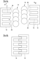
- the pickups 10,12 are constructed like a rake or a comb. They each have finger-like projections 26 and recesses 28 arranged between them.
- the projections 26 and the recesses 28 of the receivers 10, 12 are arranged in an offset manner, so that the receivers 10, 12 can be pushed into one another in sections (see FIG Figure 4b , without partial portions 14, 16).
- the partial portions 14,16 are shown by way of example as sausage slices arranged in a shingled manner.
- the partial portions 14 , 16 are pushed onto the receiving surfaces 11 , 13 of the projections 26 by the sideways movements S1 , S2 of the receivers 10 , 12 . Since the projections 26 of the receiver 10 on the one hand and the receiver 12 on the other hand have different thicknesses or heights, their contact surfaces 11,13 are in parallel offset planes, so that the partial portions 14, 16 can easily be brought into an overlapping arrangement.
- This is in Figure 4c shown (without pickups 10,12).
- comb-like pickups 10, 12 can also be used in connection with other embodiments of the invention, in which an offset of the pickup surfaces 11, 13 (additionally or only) is generated by raising/lowering the pickups 10 and/or 12 .
- a hold-down device (not shown) can be provided in order to fix the partial portions 14,16 on the base 13a and/or the receiving surfaces 11,13 as required.
- the partial portions 14,16 can be subjected to a force that presses them against the base 13a or the receiving surfaces 11,13, separately from one another, at variable times and/or locally.
- sections of the hold-down device can be moved and controlled independently of one another. Provision can be made to adapt the contact pressure to the situation in terms of time and/or location, for example to vary it while the pickups 10,12 travel under the partial portions 14,16. Ie it can be adjusted depending on a closed state of the product gripper. During the movement of the product gripper from the receiving location to the depositing location of the product, the product is preferably pressed against the receiving surfaces 10, 13 over as large an area as possible in order to secure its position.
- the other partial portion 16,14 is fixed in its position by the hold-down device.
- the partial portions 14, 16 to be picked up are not, or only locally, subjected to a fixing force by the holding-down device in order to make it easier to move them under.
- a basic idea of the present invention can be characterized, among other things, by the fact that the receiving surfaces 11,13 of the receivers 10,12 during the closing movement of the receivers 10,12, which are arranged laterally outside of the partial portions 14,16 at the beginning of the receiving process (ie the Partial portions 14,16 are arranged between the pickups 10,12), are arranged on parallel offset planes and/or are offset in parallel.
- the closing movement thus automatically makes it possible for the partial portions 14, 16 to be deposited in an overlapping manner.
Landscapes
- Engineering & Computer Science (AREA)
- Mechanical Engineering (AREA)
- Life Sciences & Earth Sciences (AREA)
- Food Science & Technology (AREA)
- Robotics (AREA)
- Wood Science & Technology (AREA)
- Zoology (AREA)
Claims (13)
- Dispositif de préhension de produit pour recevoir un produit comprenant au moins une première portion partielle (16) et une deuxième portion partielle (14), comprenantau moins un premier récepteur (12) ayant une première surface de réception (13) pour recevoir la première portion partielle (16),au moins un deuxième récepteur (10) ayant une deuxième surface de réception (11) pour recevoir la deuxième portion partielle (14),un moyen d'entraînement pour déplacer les récepteurs (10, 12) entre une première position, dans laquelle la première surface de réception (13) et la deuxième surface de réception (11) sont disposées sur des côtés opposés du produit à recevoir, et une deuxième position, dans laquelle les surfaces de réception (11, 13) se trouvent au moins partiellement sous les portions partielles (14, 16),le premier récepteur (12) étant conçu de telle sorte que la première surface de réception (13) avec la première portion partielle (16) peut être déplacée, en particulier être soulevée et/ou abaissée, sensiblement perpendiculairement par rapport à la deuxième surface de réception (11), et/ou est disposée de manière décalée par rapport à la deuxième surface de réception (11) dans ladite direction,caractérisé en ce queles parties des récepteurs (10, 12) présentant les surfaces de réception (11, 13) sont réalisées avec des épaisseurs différentes, et/ou en ce que le moyen d'entraînement est conçu de telle sorte que la première surface de réception (13) peut être déplacée d'un trajet dans une direction sensiblement perpendiculaire à la première surface de réception (13), en particulier le trajet correspondant au moins à une hauteur ou épaisseur de la deuxième portion partielle (14).
- Dispositif de préhension de produit selon la revendication 1,
caractérisé en ce que
un décalage dans ladite direction entre les première et deuxième surfaces de réception (11, 13) correspond au moins à une hauteur ou épaisseur de la deuxième portion partielle. - Dispositif de préhension de produit selon l'une des revendications précédentes,
caractérisé en ce que
les récepteurs (10, 12) sont réalisés en forme de peigne ou de râteau, en particulier des échancrures (28) et des saillies (26) des deux récepteurs (10, 12) étant disposées de façon complémentaire ou décalée les unes par rapport aux autres. - Dispositif de préhension de produit selon l'une au moins des revendications précédentes,
caractérisé en ce que
le premier et/ou le deuxième récepteur (12, 10) présentent une butée latérale (22, 20) par laquelle un mouvement de la portion partielle correspondante (16, 14) par rapport à la surface de réception (13, 11) peut être limité et/ou généré, en particulier la butée latérale (22, 20) et la surface de réception respective (13, 11) étant mobiles l'une par rapport à l'autre. - Dispositif de préhension de produit selon l'une au moins des revendications précédentes,
caractérisé en ce que
il est prévu une butée centrale (18) qui peut être disposée entre les deux portions partielles (14, 16) au moins dans la première position des récepteurs, en particulier la butée centrale (18) étant mobile. - Procédé pour recevoir un produit, comprenant au moins une première portion partielle (16) et une deuxième portion partielle (14), au moyen d'un dispositif de préhension de produit selon l'une au moins des revendications précédentes, le dispositif de préhension de produit comprenant au moins un premier récepteur (12) ayant une première surface de réception (13) pour recevoir la première portion partielle (16) et au moins un deuxième récepteur (10) ayant une deuxième surface de réception (11) pour recevoir la deuxième portion partielle (14), comprenant les étapes consistant à :- déplacer le premier récepteur (12) destiné à recevoir la première portion partielle (16) d'une position de base, dans laquelle la première surface de réception (13) est disposée de façon décalée latéralement par rapport à la première portion partielle (16) à recevoir, jusque dans une deuxième position, dans laquelle la première surface de réception (13) se trouve au moins partiellement sous la première portion partielle (16),- déplacer le deuxième récepteur (10) destiné à recevoir la deuxième portion partielle (14) d'une position de base, dans laquelle la deuxième surface de réception (11) est disposée de façon décalée latéralement par rapport à la deuxième portion partielle (14) à recevoir, jusque dans une deuxième position, dans laquelle la deuxième surface de réception (11) se trouve au moins partiellement sous la deuxième portion partielle (14),dans lequel, une fois que les portions partielles respectives (16, 14) sont reçues, le mouvement du premier et/ou du deuxième récepteur (12, 10) est poursuivi avec des surfaces de réception (13, 11) décalées sensiblement parallèlement l'une à l'autre, jusqu'à ce qu'une troisième position soit atteinte, dans laquelle les première et deuxième portions partielles (16, 14) se chevauchent au moins partiellement.
- Procédé selon la revendication 6,
caractérisé en ce que
les surfaces de réception (11, 13) sont disposées de façon décalée sensiblement parallèlement l'une à l'autre déjà avant le début des mouvements de réception, en particulier le décalage correspondant au moins à une hauteur ou épaisseur de la deuxième portion partielle (14). - Procédé selon la revendication 6 ou 7,
caractérisé en ce que
une fois que la première portion partielle (16) est reçue, la première surface de réception (13) est déplacée, en particulier soulevée, dans une direction sensiblement perpendiculaire à la première surface de réception (13) d'un trajet qui correspond au moins à une hauteur ou épaisseur de la deuxième portion partielle (14), en particulier la première surface de réception (13) étant abaissée après avoir atteint la troisième position, en particulier jusqu'à ce que la première portion partielle (16) vienne se poser en chevauchement partiel sur la deuxième portion partielle (14). - Procédé selon l'une au moins des revendications 6 à 8,
caractérisé en ce que
un mouvement relatif entre la première et/ou la deuxième portion partielle (16, 14) et la surface de réception correspondante (13, 11) est limité par une butée latérale associée (22, 20) lors du mouvement de réception, en particulier de telle sorte qu'une partie de la portion partielle correspondante (16, 14) dépasse au-delà d'un bord de la surface de réception respective (13, 11), qui est tourné vers l'autre portion partielle (14 ou 16). - Procédé selon l'une au moins des revendications 6 à 9,
caractérisé en ce que
les deux récepteurs (10, 12) sont déplacés de la première à la deuxième position de manière décalée dans le temps, de manière synchrone ou l'un après l'autre. - Procédé selon l'une au moins des revendications 6 à 10, caractérisé en ce que
avant le mouvement des récepteurs (10, 12), les portions partielles (14, 16) sont disposées l'une à côté de l'autre. - Procédé selon l'une au moins des revendications 6 à 11, caractérisé en ce que
avant ou après avoir atteint la troisième position ou après que la première portion partielle (16) vient se poser en chevauchement partiel sur la deuxième portion partielle (14), le produit est déplacé par translation et/ou rotation du dispositif de préhension de produit, et ensuite il est déposé, en particulier dans un emballage, en particulier les récepteurs (12, 10) étant animés d'un mouvement d'ouverture de manière synchrone, de manière décalée dans le temps ou l'un après l'autre, lors de la dépose du produit. - Procédé selon l'une au moins des revendications 6 à 12, caractérisé en ce que
une butée latérale (22, 20) est associée au premier et/ou au deuxième récepteur (12, 10), la butée latérale (22, 20) et la surface de réception correspondante (13, 11) étant déplacées l'une par rapport à l'autre afin d'influencer la position de la portion partielle correspondante (16, 14), en particulier lors d'un mouvement d'ouverture des récepteurs (12, 11) et lors de la dépose du produit.
Applications Claiming Priority (1)
| Application Number | Priority Date | Filing Date | Title |
|---|---|---|---|
| DE102017100620.6A DE102017100620A1 (de) | 2017-01-13 | 2017-01-13 | Produktgreifer |
Publications (2)
| Publication Number | Publication Date |
|---|---|
| EP3348501A1 EP3348501A1 (fr) | 2018-07-18 |
| EP3348501B1 true EP3348501B1 (fr) | 2022-03-09 |
Family
ID=60942917
Family Applications (1)
| Application Number | Title | Priority Date | Filing Date |
|---|---|---|---|
| EP18150660.1A Active EP3348501B1 (fr) | 2017-01-13 | 2018-01-08 | Dispositif de préhension de produit |
Country Status (2)
| Country | Link |
|---|---|
| EP (1) | EP3348501B1 (fr) |
| DE (1) | DE102017100620A1 (fr) |
Families Citing this family (4)
| Publication number | Priority date | Publication date | Assignee | Title |
|---|---|---|---|---|
| DE102018130632A1 (de) * | 2018-12-03 | 2020-06-04 | Weber Maschinenbau Gmbh Breidenbach | Produktgreifer mit zentralem Anschlag |
| DE102020129750A1 (de) | 2020-11-11 | 2022-05-12 | Multivac Sepp Haggenmüller Se & Co. Kg | Verfahren zum Quer-Positionieren eines zu transportierenden Artikels |
| DE102024108902A1 (de) * | 2024-03-28 | 2025-10-02 | Multivac Sepp Haggenmüller Se & Co. Kg | Greiferanordnung mit Stützfläche für zu transportierendes Produkt |
| DE102024122072B3 (de) * | 2024-08-02 | 2025-12-04 | Festo Se & Co. Kg | Verwendung eines Handhabungssystems zur Manipulation von Werkstücken aus biegeschlaffen Materialien und Schlitten für ein Handhabungssystem |
Family Cites Families (11)
| Publication number | Priority date | Publication date | Assignee | Title |
|---|---|---|---|---|
| DE3642123A1 (de) * | 1986-12-10 | 1988-06-16 | Thurne Gmbh | Einrichtung zum ablegen von scheibenfoermigen nahrungsmittelprodukten |
| DE4319171A1 (de) * | 1993-06-09 | 1994-12-15 | Dixie Union Verpackungen Gmbh | Vorrichtung zum schindelartigen Anordnen von aufgeschnittenen Gütern |
| NO345806B1 (no) | 2003-10-28 | 2021-08-16 | Aew Delford Systems Ltd | Gripe- og plasseringsanordning |
| DE102008019028A1 (de) | 2008-04-15 | 2009-10-22 | Hochland Natec Gmbh | Verfahren und Vorrichtung zum Stapeln verpackter Lebensmittelscheiben |
| DE102009012332A1 (de) | 2009-03-09 | 2010-09-16 | Weber Maschinenbau Gmbh Breidenbach | Produktgreifer |
| DE102009030012A1 (de) | 2009-06-23 | 2010-12-30 | Weber Maschinenbau Gmbh Breidenbach | Produktgreifer |
| DE102012001831B4 (de) * | 2012-02-01 | 2015-03-19 | Hochland Se | Verfahren und Vorrichtung zum Trennen und Stapeln von Lebensmittelscheiben |
| DE102013113199A1 (de) * | 2013-11-28 | 2015-05-28 | Textor Maschinenbau GmbH | Vorrichtung und Verfahren zum Erstellen von Formatsätzen aus Kombinationsportionen |
| EP3034250B1 (fr) * | 2014-12-17 | 2017-05-31 | Thurne-Middleby Ltd. | Dispositif de préhension pour saisir et libérer un groupe de tranches d'aliment |
| DE102015104055A1 (de) * | 2015-03-18 | 2016-09-22 | Textor Maschinenbau GmbH | Überlappungsvorrichtung |
| DE102015003633A1 (de) | 2015-03-19 | 2016-10-06 | Weber Maschinenbau Gmbh Breidenbach | Portionsgreifer mit nichtlinearer Schaufelvorderkante |
-
2017
- 2017-01-13 DE DE102017100620.6A patent/DE102017100620A1/de not_active Withdrawn
-
2018
- 2018-01-08 EP EP18150660.1A patent/EP3348501B1/fr active Active
Also Published As
| Publication number | Publication date |
|---|---|
| DE102017100620A1 (de) | 2018-07-19 |
| EP3348501A1 (fr) | 2018-07-18 |
Similar Documents
| Publication | Publication Date | Title |
|---|---|---|
| EP3348501B1 (fr) | Dispositif de préhension de produit | |
| EP3260402B1 (fr) | Système empileur de caisses | |
| DE102008009993A1 (de) | Verfahren zum Separieren einer Anzahl von Vials aus einer Vielzahl von in mehreren Reihen angeordneten Vials und Vorrichtung hierfür | |
| EP0553724B1 (fr) | Procédé et dispositif pour fabriquer des piles bien déterminées de feuilles pliées ou non-pliées ou d'objets sous forme de feuilles | |
| EP3339221A2 (fr) | Dispositif et procédé destinés à la manipulation de produits | |
| DE102012204030A1 (de) | Verfahren und Vorrichtung zur Übergabe von Artikellagen zwischen benachbarten Modulen | |
| EP2939965B1 (fr) | Dispositif de poussée pour un dispositif de palettisation avec un poussoir, un guide d'arrêt en butée et deux guides latéraux | |
| EP1620338A2 (fr) | Procede et dispositif pour manoeuvrer des objets en forme de tiges | |
| EP2025631B1 (fr) | Cabine d'empilage dépilage | |
| EP4276021B1 (fr) | Machine d'emballage dotée d'un dispositif de regroupement et procédé de production de groupes monocouche de produits se chevauchant partiellement | |
| EP1801047A2 (fr) | Dispositif de préhension pour des objets plats empilés | |
| EP3527500B1 (fr) | Dispositif d'emballage pour articles et procédés de fonctionnement d'un dispositif d'emballage permettant de manipuler des coupes d'emballage planes | |
| EP3841043B1 (fr) | Dispositif de palettisation et procédé permettant de faire fonctionner un dispositif de palettisation | |
| DE102013212329A1 (de) | Verpackung von biegeschlaffen Bauteilen | |
| DE3141075A1 (de) | Zufuehreinrichtung fuer blechstreifenstapel zur zufuhr zu einem stanzautomaten | |
| EP4408752B1 (fr) | Procédé et dispositif pour acheminer un groupe de produits de l'industrie du tabac, en tant que contenu d'emballage, jusqu'à une pièce découpée pour un emballage pour des produits de l'industrie du tabac | |
| EP4455063A1 (fr) | Unité d'alimentation de flans et procédé pour son fonctionnement | |
| EP1829805B1 (fr) | Dispositif destiné à la séparation de pièces découpées de cartonnages | |
| EP1851144B1 (fr) | Dispositif de rotation | |
| DE102021202108A1 (de) | Verfahren und Vorrichtung zum Verkleben mehrerer für ein jeweiliges Gebinde vorgesehener Artikel | |
| WO2002098738A1 (fr) | Dispositif pour prendre des sacs de supports de piles et pour les separer les uns des autres | |
| DE19821918B4 (de) | Verfahren zum Fördern von Produkten und Handhabungseinheit zur Durchführung des Verfahrens | |
| DE102018130632A1 (de) | Produktgreifer mit zentralem Anschlag | |
| EP2444340B1 (fr) | Système et procédé pour saisir et soulever des objets | |
| EP1655244A2 (fr) | Procédé et dispositif de séparation d'articles plats d'une pile horizontale |
Legal Events
| Date | Code | Title | Description |
|---|---|---|---|
| PUAI | Public reference made under article 153(3) epc to a published international application that has entered the european phase |
Free format text: ORIGINAL CODE: 0009012 |
|
| STAA | Information on the status of an ep patent application or granted ep patent |
Free format text: STATUS: THE APPLICATION HAS BEEN PUBLISHED |
|
| AK | Designated contracting states |
Kind code of ref document: A1 Designated state(s): AL AT BE BG CH CY CZ DE DK EE ES FI FR GB GR HR HU IE IS IT LI LT LU LV MC MK MT NL NO PL PT RO RS SE SI SK SM TR |
|
| AX | Request for extension of the european patent |
Extension state: BA ME |
|
| STAA | Information on the status of an ep patent application or granted ep patent |
Free format text: STATUS: REQUEST FOR EXAMINATION WAS MADE |
|
| 17P | Request for examination filed |
Effective date: 20190115 |
|
| RBV | Designated contracting states (corrected) |
Designated state(s): AL AT BE BG CH CY CZ DE DK EE ES FI FR GB GR HR HU IE IS IT LI LT LU LV MC MK MT NL NO PL PT RO RS SE SI SK SM TR |
|
| GRAP | Despatch of communication of intention to grant a patent |
Free format text: ORIGINAL CODE: EPIDOSNIGR1 |
|
| STAA | Information on the status of an ep patent application or granted ep patent |
Free format text: STATUS: GRANT OF PATENT IS INTENDED |
|
| INTG | Intention to grant announced |
Effective date: 20211129 |
|
| GRAS | Grant fee paid |
Free format text: ORIGINAL CODE: EPIDOSNIGR3 |
|
| GRAA | (expected) grant |
Free format text: ORIGINAL CODE: 0009210 |
|
| STAA | Information on the status of an ep patent application or granted ep patent |
Free format text: STATUS: THE PATENT HAS BEEN GRANTED |
|
| AK | Designated contracting states |
Kind code of ref document: B1 Designated state(s): AL AT BE BG CH CY CZ DE DK EE ES FI FR GB GR HR HU IE IS IT LI LT LU LV MC MK MT NL NO PL PT RO RS SE SI SK SM TR |
|
| REG | Reference to a national code |
Ref country code: CH Ref legal event code: EP Ref country code: AT Ref legal event code: REF Ref document number: 1473998 Country of ref document: AT Kind code of ref document: T Effective date: 20220315 |
|
| REG | Reference to a national code |
Ref country code: DE Ref legal event code: R096 Ref document number: 502018008976 Country of ref document: DE |
|
| REG | Reference to a national code |
Ref country code: IE Ref legal event code: FG4D Free format text: LANGUAGE OF EP DOCUMENT: GERMAN |
|
| REG | Reference to a national code |
Ref country code: LT Ref legal event code: MG9D |
|
| REG | Reference to a national code |
Ref country code: NL Ref legal event code: MP Effective date: 20220309 |
|
| PG25 | Lapsed in a contracting state [announced via postgrant information from national office to epo] |
Ref country code: SE Free format text: LAPSE BECAUSE OF FAILURE TO SUBMIT A TRANSLATION OF THE DESCRIPTION OR TO PAY THE FEE WITHIN THE PRESCRIBED TIME-LIMIT Effective date: 20220309 Ref country code: RS Free format text: LAPSE BECAUSE OF FAILURE TO SUBMIT A TRANSLATION OF THE DESCRIPTION OR TO PAY THE FEE WITHIN THE PRESCRIBED TIME-LIMIT Effective date: 20220309 Ref country code: NO Free format text: LAPSE BECAUSE OF FAILURE TO SUBMIT A TRANSLATION OF THE DESCRIPTION OR TO PAY THE FEE WITHIN THE PRESCRIBED TIME-LIMIT Effective date: 20220609 Ref country code: LT Free format text: LAPSE BECAUSE OF FAILURE TO SUBMIT A TRANSLATION OF THE DESCRIPTION OR TO PAY THE FEE WITHIN THE PRESCRIBED TIME-LIMIT Effective date: 20220309 Ref country code: HR Free format text: LAPSE BECAUSE OF FAILURE TO SUBMIT A TRANSLATION OF THE DESCRIPTION OR TO PAY THE FEE WITHIN THE PRESCRIBED TIME-LIMIT Effective date: 20220309 Ref country code: BG Free format text: LAPSE BECAUSE OF FAILURE TO SUBMIT A TRANSLATION OF THE DESCRIPTION OR TO PAY THE FEE WITHIN THE PRESCRIBED TIME-LIMIT Effective date: 20220609 |
|
| PG25 | Lapsed in a contracting state [announced via postgrant information from national office to epo] |
Ref country code: LV Free format text: LAPSE BECAUSE OF FAILURE TO SUBMIT A TRANSLATION OF THE DESCRIPTION OR TO PAY THE FEE WITHIN THE PRESCRIBED TIME-LIMIT Effective date: 20220309 Ref country code: GR Free format text: LAPSE BECAUSE OF FAILURE TO SUBMIT A TRANSLATION OF THE DESCRIPTION OR TO PAY THE FEE WITHIN THE PRESCRIBED TIME-LIMIT Effective date: 20220610 Ref country code: FI Free format text: LAPSE BECAUSE OF FAILURE TO SUBMIT A TRANSLATION OF THE DESCRIPTION OR TO PAY THE FEE WITHIN THE PRESCRIBED TIME-LIMIT Effective date: 20220309 |
|
| PG25 | Lapsed in a contracting state [announced via postgrant information from national office to epo] |
Ref country code: NL Free format text: LAPSE BECAUSE OF FAILURE TO SUBMIT A TRANSLATION OF THE DESCRIPTION OR TO PAY THE FEE WITHIN THE PRESCRIBED TIME-LIMIT Effective date: 20220309 |
|
| PG25 | Lapsed in a contracting state [announced via postgrant information from national office to epo] |
Ref country code: SM Free format text: LAPSE BECAUSE OF FAILURE TO SUBMIT A TRANSLATION OF THE DESCRIPTION OR TO PAY THE FEE WITHIN THE PRESCRIBED TIME-LIMIT Effective date: 20220309 Ref country code: SK Free format text: LAPSE BECAUSE OF FAILURE TO SUBMIT A TRANSLATION OF THE DESCRIPTION OR TO PAY THE FEE WITHIN THE PRESCRIBED TIME-LIMIT Effective date: 20220309 Ref country code: RO Free format text: LAPSE BECAUSE OF FAILURE TO SUBMIT A TRANSLATION OF THE DESCRIPTION OR TO PAY THE FEE WITHIN THE PRESCRIBED TIME-LIMIT Effective date: 20220309 Ref country code: PT Free format text: LAPSE BECAUSE OF FAILURE TO SUBMIT A TRANSLATION OF THE DESCRIPTION OR TO PAY THE FEE WITHIN THE PRESCRIBED TIME-LIMIT Effective date: 20220711 Ref country code: ES Free format text: LAPSE BECAUSE OF FAILURE TO SUBMIT A TRANSLATION OF THE DESCRIPTION OR TO PAY THE FEE WITHIN THE PRESCRIBED TIME-LIMIT Effective date: 20220309 Ref country code: EE Free format text: LAPSE BECAUSE OF FAILURE TO SUBMIT A TRANSLATION OF THE DESCRIPTION OR TO PAY THE FEE WITHIN THE PRESCRIBED TIME-LIMIT Effective date: 20220309 Ref country code: CZ Free format text: LAPSE BECAUSE OF FAILURE TO SUBMIT A TRANSLATION OF THE DESCRIPTION OR TO PAY THE FEE WITHIN THE PRESCRIBED TIME-LIMIT Effective date: 20220309 |
|
| PG25 | Lapsed in a contracting state [announced via postgrant information from national office to epo] |
Ref country code: PL Free format text: LAPSE BECAUSE OF FAILURE TO SUBMIT A TRANSLATION OF THE DESCRIPTION OR TO PAY THE FEE WITHIN THE PRESCRIBED TIME-LIMIT Effective date: 20220309 Ref country code: IS Free format text: LAPSE BECAUSE OF FAILURE TO SUBMIT A TRANSLATION OF THE DESCRIPTION OR TO PAY THE FEE WITHIN THE PRESCRIBED TIME-LIMIT Effective date: 20220709 Ref country code: AL Free format text: LAPSE BECAUSE OF FAILURE TO SUBMIT A TRANSLATION OF THE DESCRIPTION OR TO PAY THE FEE WITHIN THE PRESCRIBED TIME-LIMIT Effective date: 20220309 |
|
| REG | Reference to a national code |
Ref country code: DE Ref legal event code: R097 Ref document number: 502018008976 Country of ref document: DE |
|
| PLBE | No opposition filed within time limit |
Free format text: ORIGINAL CODE: 0009261 |
|
| STAA | Information on the status of an ep patent application or granted ep patent |
Free format text: STATUS: NO OPPOSITION FILED WITHIN TIME LIMIT |
|
| PG25 | Lapsed in a contracting state [announced via postgrant information from national office to epo] |
Ref country code: DK Free format text: LAPSE BECAUSE OF FAILURE TO SUBMIT A TRANSLATION OF THE DESCRIPTION OR TO PAY THE FEE WITHIN THE PRESCRIBED TIME-LIMIT Effective date: 20220309 |
|
| 26N | No opposition filed |
Effective date: 20221212 |
|
| PG25 | Lapsed in a contracting state [announced via postgrant information from national office to epo] |
Ref country code: SI Free format text: LAPSE BECAUSE OF FAILURE TO SUBMIT A TRANSLATION OF THE DESCRIPTION OR TO PAY THE FEE WITHIN THE PRESCRIBED TIME-LIMIT Effective date: 20220309 |
|
| P01 | Opt-out of the competence of the unified patent court (upc) registered |
Effective date: 20230522 |
|
| PG25 | Lapsed in a contracting state [announced via postgrant information from national office to epo] |
Ref country code: IT Free format text: LAPSE BECAUSE OF FAILURE TO SUBMIT A TRANSLATION OF THE DESCRIPTION OR TO PAY THE FEE WITHIN THE PRESCRIBED TIME-LIMIT Effective date: 20220309 |
|
| REG | Reference to a national code |
Ref country code: CH Ref legal event code: PL |
|
| GBPC | Gb: european patent ceased through non-payment of renewal fee |
Effective date: 20230108 |
|
| PG25 | Lapsed in a contracting state [announced via postgrant information from national office to epo] |
Ref country code: LU Free format text: LAPSE BECAUSE OF NON-PAYMENT OF DUE FEES Effective date: 20230108 |
|
| REG | Reference to a national code |
Ref country code: BE Ref legal event code: MM Effective date: 20230131 |
|
| PG25 | Lapsed in a contracting state [announced via postgrant information from national office to epo] |
Ref country code: LI Free format text: LAPSE BECAUSE OF NON-PAYMENT OF DUE FEES Effective date: 20230131 Ref country code: GB Free format text: LAPSE BECAUSE OF NON-PAYMENT OF DUE FEES Effective date: 20230108 Ref country code: CH Free format text: LAPSE BECAUSE OF NON-PAYMENT OF DUE FEES Effective date: 20230131 |
|
| PG25 | Lapsed in a contracting state [announced via postgrant information from national office to epo] |
Ref country code: FR Free format text: LAPSE BECAUSE OF NON-PAYMENT OF DUE FEES Effective date: 20230131 Ref country code: BE Free format text: LAPSE BECAUSE OF NON-PAYMENT OF DUE FEES Effective date: 20230131 |
|
| PG25 | Lapsed in a contracting state [announced via postgrant information from national office to epo] |
Ref country code: IE Free format text: LAPSE BECAUSE OF NON-PAYMENT OF DUE FEES Effective date: 20230108 |
|
| REG | Reference to a national code |
Ref country code: AT Ref legal event code: MM01 Ref document number: 1473998 Country of ref document: AT Kind code of ref document: T Effective date: 20230108 |
|
| REG | Reference to a national code |
Ref country code: DE Ref legal event code: R081 Ref document number: 502018008976 Country of ref document: DE Owner name: WEBER FOOD TECHNOLOGY SE & CO. KG, DE Free format text: FORMER OWNER: WEBER MASCHINENBAU GMBH BREIDENBACH, 35236 BREIDENBACH, DE Ref country code: DE Ref legal event code: R081 Ref document number: 502018008976 Country of ref document: DE Owner name: WEBER FOOD TECHNOLOGY GMBH, DE Free format text: FORMER OWNER: WEBER MASCHINENBAU GMBH BREIDENBACH, 35236 BREIDENBACH, DE |
|
| PG25 | Lapsed in a contracting state [announced via postgrant information from national office to epo] |
Ref country code: AT Free format text: LAPSE BECAUSE OF NON-PAYMENT OF DUE FEES Effective date: 20230108 |
|
| PG25 | Lapsed in a contracting state [announced via postgrant information from national office to epo] |
Ref country code: AT Free format text: LAPSE BECAUSE OF NON-PAYMENT OF DUE FEES Effective date: 20230108 |
|
| PG25 | Lapsed in a contracting state [announced via postgrant information from national office to epo] |
Ref country code: MC Free format text: LAPSE BECAUSE OF FAILURE TO SUBMIT A TRANSLATION OF THE DESCRIPTION OR TO PAY THE FEE WITHIN THE PRESCRIBED TIME-LIMIT Effective date: 20220309 |
|
| PG25 | Lapsed in a contracting state [announced via postgrant information from national office to epo] |
Ref country code: MC Free format text: LAPSE BECAUSE OF FAILURE TO SUBMIT A TRANSLATION OF THE DESCRIPTION OR TO PAY THE FEE WITHIN THE PRESCRIBED TIME-LIMIT Effective date: 20220309 |
|
| REG | Reference to a national code |
Ref country code: DE Ref legal event code: R081 Ref document number: 502018008976 Country of ref document: DE Owner name: WEBER FOOD TECHNOLOGY SE & CO. KG, DE Free format text: FORMER OWNER: WEBER FOOD TECHNOLOGY GMBH, 35236 BREIDENBACH, DE |
|
| PG25 | Lapsed in a contracting state [announced via postgrant information from national office to epo] |
Ref country code: CY Free format text: LAPSE BECAUSE OF FAILURE TO SUBMIT A TRANSLATION OF THE DESCRIPTION OR TO PAY THE FEE WITHIN THE PRESCRIBED TIME-LIMIT; INVALID AB INITIO Effective date: 20180108 |
|
| PG25 | Lapsed in a contracting state [announced via postgrant information from national office to epo] |
Ref country code: HU Free format text: LAPSE BECAUSE OF FAILURE TO SUBMIT A TRANSLATION OF THE DESCRIPTION OR TO PAY THE FEE WITHIN THE PRESCRIBED TIME-LIMIT; INVALID AB INITIO Effective date: 20180108 |
|
| PG25 | Lapsed in a contracting state [announced via postgrant information from national office to epo] |
Ref country code: TR Free format text: LAPSE BECAUSE OF FAILURE TO SUBMIT A TRANSLATION OF THE DESCRIPTION OR TO PAY THE FEE WITHIN THE PRESCRIBED TIME-LIMIT Effective date: 20220309 |
|
| PGFP | Annual fee paid to national office [announced via postgrant information from national office to epo] |
Ref country code: DE Payment date: 20260120 Year of fee payment: 9 |