EP3348670A1 - Kaltgasspritzsystem mit variablen massgeschneiderten pulverpatronen - Google Patents
Kaltgasspritzsystem mit variablen massgeschneiderten pulverpatronen Download PDFInfo
- Publication number
- EP3348670A1 EP3348670A1 EP18151490.2A EP18151490A EP3348670A1 EP 3348670 A1 EP3348670 A1 EP 3348670A1 EP 18151490 A EP18151490 A EP 18151490A EP 3348670 A1 EP3348670 A1 EP 3348670A1
- Authority
- EP
- European Patent Office
- Prior art keywords
- powder
- binder
- feedstock cartridge
- feedstock
- cartridge
- Prior art date
- Legal status (The legal status is an assumption and is not a legal conclusion. Google has not performed a legal analysis and makes no representation as to the accuracy of the status listed.)
- Granted
Links
Images



Classifications
-
- B—PERFORMING OPERATIONS; TRANSPORTING
- B22—CASTING; POWDER METALLURGY
- B22F—WORKING METALLIC POWDER; MANUFACTURE OF ARTICLES FROM METALLIC POWDER; MAKING METALLIC POWDER; APPARATUS OR DEVICES SPECIALLY ADAPTED FOR METALLIC POWDER
- B22F1/00—Metallic powder; Treatment of metallic powder, e.g. to facilitate working or to improve properties
- B22F1/10—Metallic powder containing lubricating or binding agents; Metallic powder containing organic material
- B22F1/102—Metallic powder coated with organic material
-
- B—PERFORMING OPERATIONS; TRANSPORTING
- B05—SPRAYING OR ATOMISING IN GENERAL; APPLYING FLUENT MATERIALS TO SURFACES, IN GENERAL
- B05B—SPRAYING APPARATUS; ATOMISING APPARATUS; NOZZLES
- B05B7/00—Spraying apparatus for discharge of liquids or other fluent materials from two or more sources, e.g. of liquid and air, of powder and gas
- B05B7/14—Spraying apparatus for discharge of liquids or other fluent materials from two or more sources, e.g. of liquid and air, of powder and gas designed for spraying particulate materials
- B05B7/1404—Arrangements for supplying particulate material
- B05B7/144—Arrangements for supplying particulate material the means for supplying particulate material comprising moving mechanical means
-
- B—PERFORMING OPERATIONS; TRANSPORTING
- B05—SPRAYING OR ATOMISING IN GENERAL; APPLYING FLUENT MATERIALS TO SURFACES, IN GENERAL
- B05B—SPRAYING APPARATUS; ATOMISING APPARATUS; NOZZLES
- B05B7/00—Spraying apparatus for discharge of liquids or other fluent materials from two or more sources, e.g. of liquid and air, of powder and gas
- B05B7/16—Spraying apparatus for discharge of liquids or other fluent materials from two or more sources, e.g. of liquid and air, of powder and gas incorporating means for heating or cooling the material to be sprayed
- B05B7/1686—Spraying apparatus for discharge of liquids or other fluent materials from two or more sources, e.g. of liquid and air, of powder and gas incorporating means for heating or cooling the material to be sprayed involving vaporisation of the material to be sprayed or of an atomising-fluid-generating product
-
- B—PERFORMING OPERATIONS; TRANSPORTING
- B05—SPRAYING OR ATOMISING IN GENERAL; APPLYING FLUENT MATERIALS TO SURFACES, IN GENERAL
- B05B—SPRAYING APPARATUS; ATOMISING APPARATUS; NOZZLES
- B05B7/00—Spraying apparatus for discharge of liquids or other fluent materials from two or more sources, e.g. of liquid and air, of powder and gas
- B05B7/16—Spraying apparatus for discharge of liquids or other fluent materials from two or more sources, e.g. of liquid and air, of powder and gas incorporating means for heating or cooling the material to be sprayed
- B05B7/22—Spraying apparatus for discharge of liquids or other fluent materials from two or more sources, e.g. of liquid and air, of powder and gas incorporating means for heating or cooling the material to be sprayed electrically, magnetically or electromagnetically, e.g. by arc
-
- B—PERFORMING OPERATIONS; TRANSPORTING
- B05—SPRAYING OR ATOMISING IN GENERAL; APPLYING FLUENT MATERIALS TO SURFACES, IN GENERAL
- B05B—SPRAYING APPARATUS; ATOMISING APPARATUS; NOZZLES
- B05B7/00—Spraying apparatus for discharge of liquids or other fluent materials from two or more sources, e.g. of liquid and air, of powder and gas
- B05B7/16—Spraying apparatus for discharge of liquids or other fluent materials from two or more sources, e.g. of liquid and air, of powder and gas incorporating means for heating or cooling the material to be sprayed
- B05B7/22—Spraying apparatus for discharge of liquids or other fluent materials from two or more sources, e.g. of liquid and air, of powder and gas incorporating means for heating or cooling the material to be sprayed electrically, magnetically or electromagnetically, e.g. by arc
- B05B7/228—Spraying apparatus for discharge of liquids or other fluent materials from two or more sources, e.g. of liquid and air, of powder and gas incorporating means for heating or cooling the material to be sprayed electrically, magnetically or electromagnetically, e.g. by arc using electromagnetic radiation, e.g. laser
-
- B—PERFORMING OPERATIONS; TRANSPORTING
- B05—SPRAYING OR ATOMISING IN GENERAL; APPLYING FLUENT MATERIALS TO SURFACES, IN GENERAL
- B05D—PROCESSES FOR APPLYING FLUENT MATERIALS TO SURFACES, IN GENERAL
- B05D7/00—Processes, other than flocking, specially adapted for applying liquids or other fluent materials to particular surfaces or for applying particular liquids or other fluent materials
- B05D7/14—Processes, other than flocking, specially adapted for applying liquids or other fluent materials to particular surfaces or for applying particular liquids or other fluent materials to metal, e.g. car bodies
-
- C—CHEMISTRY; METALLURGY
- C23—COATING METALLIC MATERIAL; COATING MATERIAL WITH METALLIC MATERIAL; CHEMICAL SURFACE TREATMENT; DIFFUSION TREATMENT OF METALLIC MATERIAL; COATING BY VACUUM EVAPORATION, BY SPUTTERING, BY ION IMPLANTATION OR BY CHEMICAL VAPOUR DEPOSITION, IN GENERAL; INHIBITING CORROSION OF METALLIC MATERIAL OR INCRUSTATION IN GENERAL
- C23C—COATING METALLIC MATERIAL; COATING MATERIAL WITH METALLIC MATERIAL; SURFACE TREATMENT OF METALLIC MATERIAL BY DIFFUSION INTO THE SURFACE, BY CHEMICAL CONVERSION OR SUBSTITUTION; COATING BY VACUUM EVAPORATION, BY SPUTTERING, BY ION IMPLANTATION OR BY CHEMICAL VAPOUR DEPOSITION, IN GENERAL
- C23C24/00—Coating starting from inorganic powder
- C23C24/02—Coating starting from inorganic powder by application of pressure only
- C23C24/04—Impact or kinetic deposition of particles
-
- C—CHEMISTRY; METALLURGY
- C23—COATING METALLIC MATERIAL; COATING MATERIAL WITH METALLIC MATERIAL; CHEMICAL SURFACE TREATMENT; DIFFUSION TREATMENT OF METALLIC MATERIAL; COATING BY VACUUM EVAPORATION, BY SPUTTERING, BY ION IMPLANTATION OR BY CHEMICAL VAPOUR DEPOSITION, IN GENERAL; INHIBITING CORROSION OF METALLIC MATERIAL OR INCRUSTATION IN GENERAL
- C23C—COATING METALLIC MATERIAL; COATING MATERIAL WITH METALLIC MATERIAL; SURFACE TREATMENT OF METALLIC MATERIAL BY DIFFUSION INTO THE SURFACE, BY CHEMICAL CONVERSION OR SUBSTITUTION; COATING BY VACUUM EVAPORATION, BY SPUTTERING, BY ION IMPLANTATION OR BY CHEMICAL VAPOUR DEPOSITION, IN GENERAL
- C23C24/00—Coating starting from inorganic powder
- C23C24/08—Coating starting from inorganic powder by application of heat or pressure and heat
- C23C24/082—Coating starting from inorganic powder by application of heat or pressure and heat without intermediate formation of a liquid in the layer
- C23C24/085—Coating with metallic material, i.e. metals or metal alloys, optionally comprising hard particles, e.g. oxides, carbides or nitrides
-
- B—PERFORMING OPERATIONS; TRANSPORTING
- B22—CASTING; POWDER METALLURGY
- B22F—WORKING METALLIC POWDER; MANUFACTURE OF ARTICLES FROM METALLIC POWDER; MAKING METALLIC POWDER; APPARATUS OR DEVICES SPECIALLY ADAPTED FOR METALLIC POWDER
- B22F2999/00—Aspects linked to processes or compositions used in powder metallurgy
Definitions
- the present disclosure relates to a cold spray system and, more particularly, to material feedstock cartridges therefor.
- Cold spray also often referred to as dynamic solid state deposition or kinetic spray, is a process that uses compressed gas to accelerate powdered materials through a supersonic nozzle toward a substrate.
- the powder particles impact the substrate and consolidate through a process of plastic deformation. This plastic flow creates a cold weld between the incoming powder particles and the substrate.
- a feedstock cartridge for a cold spray system can include at least one powder; and a binder that binds at least two particles of the at least one powder to form a feedstock cartridge.
- An embodiment of the present disclosure may include, wherein the binder is at least one of a wax, Polyvinylpyrrolidone (PVP), Poly(vinyl alcohol) (PVOH, PVA, or PVA1).
- PVP Polyvinylpyrrolidone
- PVH Poly(vinyl alcohol)
- PVA Poly(vinyl alcohol)
- a further embodiment of the present disclosure may include, wherein the binder vaporizes at less than about 150 degree C.
- a further embodiment of the present disclosure may include, wherein the binder completely covers each particle of the at least one powder.
- a further embodiment of the present disclosure may include, wherein the binder partially covers each particle of the at least one powder.
- a further embodiment of the present disclosure may include, wherein the feedstock cartridge includes a multiple of powders.
- a further embodiment of the present disclosure may include, wherein each of the multiple of powders are intermixed in at least one layer defined by the feedstock cartridge.
- a further embodiment of the present disclosure may include, wherein one of the multiple of powders form a gradient from a first end of the feedstock cartridge to an opposite end of the feedstock cartridge.
- a further embodiment of the present disclosure may include, wherein at least one of the multiple of powders is a peening material.
- a cold spray system can include a material feed hopper to receive a feedstock cartridge of at least one powder and a binder; and a desolidifier downstream of the material feed hopper to at least partially desolidify a portion of the feedstock cartridge.
- the feedstock cartridge may have any of the features discussed above.
- a further embodiment of the present disclosure may include, wherein the desolidifier includes an auger that grinds off a portion of the feedstock cartridge.
- a further embodiment of the present disclosure may include, wherein the desolidifier includes a laser that melts away at the feedstock cartridge.
- a further embodiment of the present disclosure may include, wherein the laser is operable to vaporize the binder.
- a further embodiment of the present disclosure may include, wherein the material feed hopper includes a feed mechanism to drive the feedstock cartridge toward the desolidifier.
- a further embodiment of the present disclosure may include a heater downstream of the desolidifier to receive the portion of the feedstock cartridge and vaporize the binder.
- a further embodiment of the present disclosure may include, wherein the heater includes a heated coil to vaporize the binder and communicate the at least one powder to a spray gun.
- a method for manufacturing a feedstock cartridge according to one disclosed non-limiting embodiment of the present disclosure can include coating particles of at least one powder with a binder to bind the particles; and forming a feedstock cartridge from the coated particles.
- a further embodiment of the present disclosure may include coating the particles of a first powder; coating the particles of a second powder; and mixing the coated particles of the first and second powder in a desired ratio.
- a further embodiment of the present disclosure may include, introducing the binder as a vapor.
- a further embodiment of the present disclosure may include introduced the binder as a liquid with a solvent.
- FIG. 1 schematically illustrates a cold spray system 20.
- cold spray refers to a materials deposition process in which relatively small particles (ranging in size, without limitation, from 5 to 500 micrometers ( ⁇ m) in diameter) are accelerated to high velocities (typically, but without limitation, 300 to 1200 meters/second), at a relatively low temperatures (100-500°C) gas stream to develop a coating or deposit by impact upon a substrate.
- velocities typically, but without limitation, 300 to 1200 meters/second
- Various terms such as “kinetic energy metallization,” “kinetic metallization,” “kinetic spraying,” “high-velocity powder deposition,” and “cold gas-dynamic spray method have been used to refer to this technique.
- the cold spray system 20 generally includes a motive gas system 30, a material feed hopper 40 that receives a feedstock cartridge 50, a desolidifier 60, a heater 70, and a spray gun 80.
- the motive gas system 30 is in fluid communication with the material feed hopper 40, the desolidifier 60, the heater 70, and the spray gun 80.
- Feedstock powder particles that are in the feedstock cartridge 50 are communicated via the inert gas from the motive gas system 30 for introduction into the spray gun 80 to accelerate the gas.
- Various pressurized inert gases can be used in the cold spray technique to include but not be limited to helium or nitrogen.
- the subsequent high-velocity impact of the particles onto a substrate disrupts the oxide films on the particle and substrate, which presses their atomic structures into intimate contact with one another under momentarily high interfacial pressures and temperatures.
- the feedstock cartridge 50 includes one or more powders 52A, 52B, ... 52n that are coated and solidified via a binder 54 to form a self-contained unit that may be specifically tailored to a particular application process.
- the binder 54 may be a wax, Polyvinylpyrrolidone (PVP), Poly(vinyl alcohol) (PVOH, PVA, or PVA1) and/or other materials that vaporize at a relatively low temperature, e.g., less than about 150 degrees C and more specifically about 120 degrees C.
- the feedstock cartridge 50 provides functionally graded materials of the one or more powders 52A, 52B, ..., 52n in a "stick" form.
- the particles of the one or more powders 52A, 52B, ..., 52n are essentially interconnected, or bound together, by the binder 54.
- the binder 54 can be continuous, i.e. covering completely each powder particle or patchy, i.e. only partially covering each powder particle, but in either case, the powder particles (which may be metal) are bound within each layer as well as to maintain the different layers together.
- the first powder 52A is located in a bottom layer XI of the feedstock cartridge 50 which is sprayed first and the second powder 52B is located at a top layer Xn of the feedstock cartridge 50.
- the powder composition of the example of the feedstock cartridge 50 then gradually changes, for example, from 100% first powder 52A in the bottom layer XI to 100% second powder 52B in the top layer Xn.
- the gradual change may be formed via a multiple of layers X2, X3, etc.
- each layer may include a gradual change in mixture between the first powder 52A and the second powder 52B, e.g., 100% first powder 52A at X1, 90% first powder 52A with 10% second powder 52B at the next layer X2, 80% first powder 52A and 20% second powder 52B at the next layer X3, etc., until 100% second powder 52B is obtained at the top layer Xn.
- various other gradients as well as more than two powders may be utilized for a particular feedstock cartridge 50 such that each feedstock cartridge 50 is tailored for a particular application.
- each feedstock cartridge 50 may be tailored for a particular application and for a particular coverage area. That is, a feedstock cartridge 50 that is to be used for a smaller coverage area will have a different layer thickness in each layer for a feedstock cartridge 50 that is predefined for a larger coverage area.
- the first powder 52A may be a "peening material" which grades out during the buildup of the second powder 52B as the layers progress through the feedstock cartridge 50.
- the first powder 52A is spherical chrome carbide or nickel chrome peening particles and the second powder 52B is nickel.
- the graded out composition provides a hard phase of 75% by weight peeing material that may result in a weak bond between the nickel and the stainless steel due to significant work hardening of the nickel. Then to reinforce the bond, a third layer of 25% peening material may follow a second layer of 50% peening material, etc.
- the desolidifier 60 selectively removes portions of the feedstock cartridge 50 for communication through a conduit 90 to the heater 70.
- the desolidifier 60 is a mechanical auger that grinds away at the feedstock cartridge 50 at a predetermined rate to feed the powder composition into the conduit 90.
- the conduit 90 may at least partially encase the desolidifier 60 to collect the portions of the feedstock cartridge 50 as well as provide for communication of the inert gas from the motive gas system 30.
- the desolidifier 60 can include an auger 62 with a rough texture to grind off, or break away, portions of the cartridge 50. That is, the desolidifier 60 may rotate at a specified rate to control the material feed rate, such that a specified quantity of the feedstock cartridge 50 is removed as "chunks" into the conduit 90.
- the auger 62 may alternatively, or additionally, be heated to begin melting of the binder 54.
- the material feed hopper 40 may include a feed mechanism 42 such as a spring or other such transport device to drive the feedstock cartridge 50 toward the desolidifier 60 at a predetermined, or otherwise adjustable, rate.
- the desolidifier 60 includes a laser 64 that selectively melts an end of the feedstock cartridge 50 at a predetermined rate to feed the powder composition into the conduit 90.
- the laser 64 may be of a relatively low enough power to avoid damage to the powder 52 but is high enough to at least partially vaporize the binder 54 such that the inert gas from the motive gas system 30 need not be heated by the heater 70 prior to communication to the spray gun 80.
- the laser 64 allows the powder to break away from the feedstock cartridge 50 and permit the inert gas to communicate the powder 52 and binder 54 composition to the heater 70.
- the heater 70 includes a heated conduit coil 100 that completely vaporizes the binder 54 and heats the inert gas from the motive gas system 30.
- the temperature of the heater 70, the length of the heated conduit coil 100, and the flow rate of the pre-heated inert gas flowing therethrough may be selected so that a residence time between an entrance 102 and an exit 104 of the heated conduit coil 100 assures the binder 54 is vaporized into the gas phase. These process conditions assure that the binder 54 transitions from the solid phase to the liquid phase, then to the superheated gas phase.
- the parameters are selected so that pyrolysis of the binder 54 to lower molecular weight hydrocarbon species and elemental carbon has been eliminated or minimized as, for most applications, inclusion of carbon phases in the cold spray is to be avoided.
- the process conditions can be tailored to achieve the desired carbon concentration by the binder pyrolysis reactions. If the carbon formed by pyrolysis is sufficiently small, on the order of nanometers, the carbon will have insufficient mass to pass through the bow shock from the gun 80 and deposit with the powder 52 such that some pyrolysis may be acceptable.
- the binder 54 protects the powder 52 from air and moisture oxidation during transportation, storage, and use.
- the binder 54 enhances powder flow due to insulation from a potential electrical charge in the powder 52.
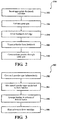
- one method 200 for operating the cold spray system 20 includes inserting a feedstock cartridge 50 into the material feed hopper 40 (step 202).
- the feedstock cartridge 50 is selected based on the desired application.
- the desolidifier 60 selectively grinds or melts away at the feedstock cartridge 50 for communication to the heater 70 via the inert gas from the motive gas system 30 (step 204).
- the heater 70 then completely vaporizes the binder 54 from the powder 52 (step 206). From the heater 70, the powder 52 is communicated through the spray gun 80 for mechanical interlocking and metallurgical bonding from re-crystallization at highly strained particle interfaces (step 208).
- another method 300 for manufacturing the feedstock cartridge 50 initially includes introduction of the binder 54 as a vapor into a fluidized bed that contains the powder 52.
- each powder is coated independently as different batches, i.e. one batch for powder 52A, and another batch for powder 52B, etc., (step 302).
- the binder coated powders are mixed in a separate operation to the prescribed compositions (step 304).
- individual compositions of, for example, 90% of the first powder 52A and 10% of the second powder 52B (by weight or volume) are mixed together to form a metal powder composition. Therefore, batches with different metal powder chemical compositions are achieved.
- step 306 These powders are then arranged in a column mold of layers of the desired metal compositions and layer thicknesses. Then, once the desirable powder metal feed columns are arranged, the column mold is heated such that the metal particles in the columns are fixed into place as defined by the mold to form the feedstock cartridge 50 (step 308). The binder 54 thereby fixes in place the layers in the feedstock cartridge 50.
- another method 400 for manufacturing the feedstock cartridge 50 initially includes the arrangement of powders 52A, 52B, ... 52n in a mold (step 402).
- the powders 52A, 52B, ... 52n form a composition and thickness per the desired distribution.
- the binder 54 is then introduced as a vapor to flow through the particles the arrangement of powders 52A, 52B, ... 52n (step 404) and the temperature distribution is controlled so that the binder 54 covers and coats the particles of the powders.
- the composition is cooled down (step 406), and cartridges 50 of specific cross section (step 408) are cut to feed the material feed hopper 40.
- the binder 54 is then introduced as a molten liquid (step 404A) to flow through the particles the arrangement of powders 52A, 52B, ... 52n via pump or other pressurization system.
- the binder 54 is introduced as a liquid with a solvent to flow through the arrangement of powders 52A, 52B, ... 52n via a pump or other pressurization system (step 404B, step 405).
- the solvent is then evaporated leaving a coating of binder 54 on the arrangement of powders 52A, 52B, ... 52n.
- the binder 54 may also be recovered downstream by cooling the solvent vapor for re-use.
- a fluidized bed system 500 that may be utilized to coat the powder 52 with a binder 54 so as to form the cartridge 50 therefrom generally includes a fluidized bed 502 in a tubular furnace 504 that receives the binder 54 from a binder source 506.
- the powder 52 is loaded into the fluidized bed 502 and an inert fluidization gas such as N2 from a gas source 508 is introduced to the fluidized bed 502.
- the used inert fluidization gas is ultimately collected by flowing the gas first through a bleed line 510 via valve 512 then to a liquid bubbler 514 for collection.
- the gas is directed via valve 516 and closing valve 512 to the fluidized bed 502 at the flow rate through the mass flow controller 518 to fluidize the powders inside the fluidized bed 50.
- the binder vapor is carried to the fluidized bed 502 by the fluidization gas via closing the valve 520 and opening valve 522.
- the temperature of the fluidized bed 502 is maintained at temperatures lower than solidification temperatures of the binder 54 in the fluidization gas stream, so the powders 52 in the fluidized bed 502 are coated with the binder 54 and collected in the powder collector 524.
Landscapes
- Chemical & Material Sciences (AREA)
- Engineering & Computer Science (AREA)
- Mechanical Engineering (AREA)
- Chemical Kinetics & Catalysis (AREA)
- Materials Engineering (AREA)
- Metallurgy (AREA)
- Organic Chemistry (AREA)
- Physics & Mathematics (AREA)
- Electromagnetism (AREA)
- Health & Medical Sciences (AREA)
- General Health & Medical Sciences (AREA)
- Optics & Photonics (AREA)
- Toxicology (AREA)
- Life Sciences & Earth Sciences (AREA)
- Wood Science & Technology (AREA)
- Powder Metallurgy (AREA)
- Other Surface Treatments For Metallic Materials (AREA)
Applications Claiming Priority (1)
| Application Number | Priority Date | Filing Date | Title |
|---|---|---|---|
| US15/405,970 US10226791B2 (en) | 2017-01-13 | 2017-01-13 | Cold spray system with variable tailored feedstock cartridges |
Publications (2)
| Publication Number | Publication Date |
|---|---|
| EP3348670A1 true EP3348670A1 (de) | 2018-07-18 |
| EP3348670B1 EP3348670B1 (de) | 2020-11-18 |
Family
ID=61131906
Family Applications (1)
| Application Number | Title | Priority Date | Filing Date |
|---|---|---|---|
| EP18151490.2A Active EP3348670B1 (de) | 2017-01-13 | 2018-01-12 | Kaltgasspritzsystem mit variablen massgeschneiderten pulverpatronen |
Country Status (2)
| Country | Link |
|---|---|
| US (1) | US10226791B2 (de) |
| EP (1) | EP3348670B1 (de) |
Cited By (1)
| Publication number | Priority date | Publication date | Assignee | Title |
|---|---|---|---|---|
| WO2024241015A1 (fr) | 2023-05-23 | 2024-11-28 | Safran | Procede de depot d'un revetement metallique par projection thermique et melange pour mettre en oeuvre un tel procede |
Families Citing this family (5)
| Publication number | Priority date | Publication date | Assignee | Title |
|---|---|---|---|---|
| US9335296B2 (en) | 2012-10-10 | 2016-05-10 | Westinghouse Electric Company Llc | Systems and methods for steam generator tube analysis for detection of tube degradation |
| US11935662B2 (en) | 2019-07-02 | 2024-03-19 | Westinghouse Electric Company Llc | Elongate SiC fuel elements |
| ES2955292T3 (es) | 2019-09-19 | 2023-11-29 | Westinghouse Electric Co Llc | Aparato para realizar pruebas de adherencia in situ de depósitos de pulverización en frío y procedimiento de empleo |
| US20220331914A1 (en) * | 2021-04-15 | 2022-10-20 | General Electric Company | Methods of coating components with cold spray and brazing coated components |
| CA3230518A1 (en) * | 2021-09-03 | 2023-03-09 | Christian Moreau | Method and system for cold deposition of powdered materials on a substrate |
Citations (3)
| Publication number | Priority date | Publication date | Assignee | Title |
|---|---|---|---|---|
| US5334235A (en) * | 1993-01-22 | 1994-08-02 | The Perkin-Elmer Corporation | Thermal spray method for coating cylinder bores for internal combustion engines |
| EP2942373A1 (de) * | 2014-05-09 | 2015-11-11 | United Technologies Corporation | Oberflächenbehandlung von pulvern |
| US20160279703A1 (en) * | 2013-09-16 | 2016-09-29 | The University Of Nottingham | Additive Manufacturing |
Family Cites Families (43)
| Publication number | Priority date | Publication date | Assignee | Title |
|---|---|---|---|---|
| US4789507A (en) * | 1985-10-28 | 1988-12-06 | Hoechst Celanese Corporation | Production of preceramic and ceramic fibers from friable, thermally sensitive organosilicon preceramic polymers |
| EP0643994A3 (de) * | 1993-09-20 | 1995-09-13 | Nippon Paint Co Ltd | Verfahren zur Zufuhr von Pulverlacken zu Beschichtungsgeräten und Pulverbeschichtungsvorrichtung zur Zerstäubung von Pulverlackgranulat in zerstäubbaren Pulver. |
| US5820678A (en) * | 1997-05-30 | 1998-10-13 | The Regents Of The University Of California | Solid source MOCVD system |
| US6502767B2 (en) | 2000-05-03 | 2003-01-07 | Asb Industries | Advanced cold spray system |
| US6365222B1 (en) | 2000-10-27 | 2002-04-02 | Siemens Westinghouse Power Corporation | Abradable coating applied with cold spray technique |
| US6491208B2 (en) | 2000-12-05 | 2002-12-10 | Siemens Westinghouse Power Corporation | Cold spray repair process |
| US6444259B1 (en) | 2001-01-30 | 2002-09-03 | Siemens Westinghouse Power Corporation | Thermal barrier coating applied with cold spray technique |
| US6722584B2 (en) | 2001-05-02 | 2004-04-20 | Asb Industries, Inc. | Cold spray system nozzle |
| JP3786417B2 (ja) | 2001-06-08 | 2006-06-14 | 日本電子株式会社 | コールドスプレー質量分析装置 |
| US6780458B2 (en) | 2001-08-01 | 2004-08-24 | Siemens Westinghouse Power Corporation | Wear and erosion resistant alloys applied by cold spray technique |
| US7543764B2 (en) | 2003-03-28 | 2009-06-09 | United Technologies Corporation | Cold spray nozzle design |
| US7560170B2 (en) | 2003-04-04 | 2009-07-14 | Intelligent Energy, Inc. | Surface modification of porous metal substrates using cold spray |
| EP1676309A1 (de) * | 2003-10-09 | 2006-07-05 | SNT Co., Ltd. | Elektrostatische einspannvorrichtung mit nichtgesintertem aln und herstellungsverfahren dafür |
| KR100515608B1 (ko) | 2003-12-24 | 2005-09-16 | 재단법인 포항산업과학연구원 | 분말 예열 장치가 구비된 저온 스프레이 장치 |
| ATE424257T1 (de) | 2005-03-09 | 2009-03-15 | Solmics Co Ltd | Düse zum kaltgasspritzen und vorrichtung mit solch einer düse |
| US7836593B2 (en) | 2005-03-17 | 2010-11-23 | Siemens Energy, Inc. | Cold spray method for producing gas turbine blade tip |
| US7836591B2 (en) | 2005-03-17 | 2010-11-23 | Siemens Energy, Inc. | Method for forming turbine seal by cold spray process |
| US8349396B2 (en) | 2005-04-14 | 2013-01-08 | United Technologies Corporation | Method and system for creating functionally graded materials using cold spray |
| KR101380793B1 (ko) | 2005-12-21 | 2014-04-04 | 슐저메트코(유에스)아이엔씨 | 하이브리드 플라즈마-콜드 스프레이 방법 및 장치 |
| US7959093B2 (en) | 2006-02-07 | 2011-06-14 | Honeywell International Inc. | Apparatus for applying cold-spray to small diameter bores |
| US7402277B2 (en) | 2006-02-07 | 2008-07-22 | Exxonmobil Research And Engineering Company | Method of forming metal foams by cold spray technique |
| GB2439934A (en) * | 2006-07-07 | 2008-01-16 | William Geoffrey Hopkins | Laser-assisted spray system and nozzle |
| WO2008073110A1 (en) | 2006-12-15 | 2008-06-19 | Doben Limited | Gas dynamic cold spray unit |
| WO2008098336A1 (en) | 2007-02-12 | 2008-08-21 | Doben Limited | Adjustable cold spray nozzle |
| JP5171125B2 (ja) | 2007-06-25 | 2013-03-27 | プラズマ技研工業株式会社 | コールドスプレー用のノズル及びそのコールドスプレー用のノズルを用いたコールドスプレー装置 |
| US8597724B2 (en) | 2007-07-06 | 2013-12-03 | United Technologies Corporation | Corrosion protective coating through cold spray |
| US8192799B2 (en) | 2008-12-03 | 2012-06-05 | Asb Industries, Inc. | Spray nozzle assembly for gas dynamic cold spray and method of coating a substrate with a high temperature coating |
| US8020509B2 (en) | 2009-01-08 | 2011-09-20 | General Electric Company | Apparatus, systems, and methods involving cold spray coating |
| US8486249B2 (en) | 2009-01-29 | 2013-07-16 | Honeywell International Inc. | Cold spray and anodization repair process for restoring worn aluminum parts |
| MY165224A (en) | 2009-12-04 | 2018-03-13 | Univ Michigan Regents | Coaxial laser assisted cold spray nozzle |
| KR101171682B1 (ko) | 2010-04-19 | 2012-08-07 | 아주대학교산학협력단 | 저온 분사 방법을 이용한 알루미늄 또는 알루미늄 합금 표면의 질화처리방법 |
| US9328918B2 (en) | 2010-05-28 | 2016-05-03 | General Electric Company | Combustion cold spray |
| CN102892926A (zh) | 2010-12-22 | 2013-01-23 | 等离子技术工业株式会社 | 冷喷涂用喷嘴以及使用该冷喷涂用喷嘴的冷喷涂装置 |
| US8906450B1 (en) | 2011-09-28 | 2014-12-09 | Hanergy Holding Group Ltd. | Cold spray system nozzle |
| WO2013049274A2 (en) | 2011-09-29 | 2013-04-04 | H.C. Starck, Inc. | Large-area sputtering targets and methods of manufacturing large-area sputtering targets |
| US8591986B1 (en) | 2012-08-17 | 2013-11-26 | General Electric Company | Cold spray deposition method |
| US8584732B1 (en) | 2012-09-24 | 2013-11-19 | The United States Of America As Represented By The Secretary Of The Army | Mold release method for a cold spray process |
| US9394063B2 (en) | 2013-03-15 | 2016-07-19 | Bell Helicopter Textron Inc. | Methods utilizing cold spray techniques for repairing and protecting rotary components of aviation propulsion systems |
| US9109291B2 (en) | 2013-05-24 | 2015-08-18 | General Electric Company | Cold spray coating process |
| WO2015047545A1 (en) | 2013-09-27 | 2015-04-02 | United Technologies Corporation | Self-peening feedstock materials for cold spray deposition |
| EP3060694B1 (de) | 2013-10-24 | 2022-01-12 | Raytheon Technologies Corporation | Verfahren zur verbesserung der haftfestigkeit durch in-situ-kugelstrahlen |
| EP2871002B1 (de) * | 2013-11-08 | 2016-02-17 | VLN Advanced Technologies Inc. | Integriertes Flüssigkeitsstrahlsystem zum Abtragen, Vorbehandeln und Beschichten eines Bauteils |
| US9433957B2 (en) | 2014-01-08 | 2016-09-06 | United Technologies Corporation | Cold spray systems with in-situ powder manufacturing |
-
2017
- 2017-01-13 US US15/405,970 patent/US10226791B2/en active Active
-
2018
- 2018-01-12 EP EP18151490.2A patent/EP3348670B1/de active Active
Patent Citations (3)
| Publication number | Priority date | Publication date | Assignee | Title |
|---|---|---|---|---|
| US5334235A (en) * | 1993-01-22 | 1994-08-02 | The Perkin-Elmer Corporation | Thermal spray method for coating cylinder bores for internal combustion engines |
| US20160279703A1 (en) * | 2013-09-16 | 2016-09-29 | The University Of Nottingham | Additive Manufacturing |
| EP2942373A1 (de) * | 2014-05-09 | 2015-11-11 | United Technologies Corporation | Oberflächenbehandlung von pulvern |
Cited By (2)
| Publication number | Priority date | Publication date | Assignee | Title |
|---|---|---|---|---|
| WO2024241015A1 (fr) | 2023-05-23 | 2024-11-28 | Safran | Procede de depot d'un revetement metallique par projection thermique et melange pour mettre en oeuvre un tel procede |
| FR3149021A1 (fr) * | 2023-05-23 | 2024-11-29 | Safran | Procédé de depôt d’un revêtement métallique par projection thermique, ensemble et mélange pour mettre en œuvre un tel procédé |
Also Published As
| Publication number | Publication date |
|---|---|
| US20180200755A1 (en) | 2018-07-19 |
| US10226791B2 (en) | 2019-03-12 |
| EP3348670B1 (de) | 2020-11-18 |
Similar Documents
| Publication | Publication Date | Title |
|---|---|---|
| EP3348670B1 (de) | Kaltgasspritzsystem mit variablen massgeschneiderten pulverpatronen | |
| Guo et al. | Cold spray: over 30 years of development toward a hot future | |
| EP1674595B1 (de) | Strukturelle Reparatur durch Kaltspritzverfahren von Aluminumwerkstoffen | |
| EP3060694B1 (de) | Verfahren zur verbesserung der haftfestigkeit durch in-situ-kugelstrahlen | |
| DE60210267T2 (de) | Vorrichtung und verfahren zur festkörper aufbringung und verdichtung von pulverteilchen mittels hochgeschwindigkeit und thermisch plastischer verformung | |
| EP1666636A1 (de) | Vakuum-Kaltspritzverfahren | |
| Irissou et al. | Review on cold spray process and technology: part I—intellectual property | |
| EP1705266B1 (de) | Auftragen einer Haftbeschichtung auf Motorbauteile mittels eines Kaltsprühverfahrens | |
| Xu et al. | Cold spray deposition of thermoplastic powder | |
| EP1659195B1 (de) | Kaltes, gasdynamisches Spritzverfahren von hochfestem Kupfer | |
| US9328918B2 (en) | Combustion cold spray | |
| EP1666635A1 (de) | Reparatur von Bauteilen aus Superlegierungen unter Verwendung von Kaltgasspritzen | |
| EP1674596A1 (de) | Laserstrahlveredelungen von kaltgasgespritzten Abscheidungen | |
| US6602545B1 (en) | Method of directly making rapid prototype tooling having free-form shape | |
| WO2006137929A2 (en) | Coated armor system and process for making the same | |
| US7820238B2 (en) | Cold sprayed metal matrix composites | |
| EP3049544B1 (de) | Selbstkörnende ausgangsmaterialien für kalte sprühablagerung | |
| KR20080065480A (ko) | 저온분사공정을 이용한 텅스텐/구리 복합재료의 코팅방법 | |
| CN101218369B (zh) | 用于材料沉积的方法和装置 | |
| Tillmann et al. | Investigation of HVOF-ID spraying with WC-CoCr-15+ 5 μm feedstock powder | |
| CN118253781A (zh) | 由两种或更多种材料产生粉末的系统和方法 | |
| KR20130117213A (ko) | 초경합금의 박막 코팅방법 | |
| Gaertner et al. | Present status and future prospects of cold spraying | |
| Zhou et al. | In situ synthesis of FeAl intermetallic coatings by wire electrical explosion-spraying | |
| Wang et al. | Thermal shock and ablation behavior of tungsten nozzle produced by plasma spray forming and hot isostatic pressing |
Legal Events
| Date | Code | Title | Description |
|---|---|---|---|
| PUAI | Public reference made under article 153(3) epc to a published international application that has entered the european phase |
Free format text: ORIGINAL CODE: 0009012 |
|
| STAA | Information on the status of an ep patent application or granted ep patent |
Free format text: STATUS: THE APPLICATION HAS BEEN PUBLISHED |
|
| AK | Designated contracting states |
Kind code of ref document: A1 Designated state(s): AL AT BE BG CH CY CZ DE DK EE ES FI FR GB GR HR HU IE IS IT LI LT LU LV MC MK MT NL NO PL PT RO RS SE SI SK SM TR |
|
| AX | Request for extension of the european patent |
Extension state: BA ME |
|
| STAA | Information on the status of an ep patent application or granted ep patent |
Free format text: STATUS: REQUEST FOR EXAMINATION WAS MADE |
|
| STAA | Information on the status of an ep patent application or granted ep patent |
Free format text: STATUS: EXAMINATION IS IN PROGRESS |
|
| 17P | Request for examination filed |
Effective date: 20190118 |
|
| RBV | Designated contracting states (corrected) |
Designated state(s): AL AT BE BG CH CY CZ DE DK EE ES FI FR GB GR HR HU IE IS IT LI LT LU LV MC MK MT NL NO PL PT RO RS SE SI SK SM TR |
|
| 17Q | First examination report despatched |
Effective date: 20190213 |
|
| GRAP | Despatch of communication of intention to grant a patent |
Free format text: ORIGINAL CODE: EPIDOSNIGR1 |
|
| STAA | Information on the status of an ep patent application or granted ep patent |
Free format text: STATUS: GRANT OF PATENT IS INTENDED |
|
| INTG | Intention to grant announced |
Effective date: 20200529 |
|
| GRAS | Grant fee paid |
Free format text: ORIGINAL CODE: EPIDOSNIGR3 |
|
| GRAA | (expected) grant |
Free format text: ORIGINAL CODE: 0009210 |
|
| STAA | Information on the status of an ep patent application or granted ep patent |
Free format text: STATUS: THE PATENT HAS BEEN GRANTED |
|
| AK | Designated contracting states |
Kind code of ref document: B1 Designated state(s): AL AT BE BG CH CY CZ DE DK EE ES FI FR GB GR HR HU IE IS IT LI LT LU LV MC MK MT NL NO PL PT RO RS SE SI SK SM TR |
|
| REG | Reference to a national code |
Ref country code: GB Ref legal event code: FG4D |
|
| REG | Reference to a national code |
Ref country code: CH Ref legal event code: EP |
|
| REG | Reference to a national code |
Ref country code: IE Ref legal event code: FG4D |
|
| REG | Reference to a national code |
Ref country code: DE Ref legal event code: R096 Ref document number: 602018009693 Country of ref document: DE |
|
| REG | Reference to a national code |
Ref country code: AT Ref legal event code: REF Ref document number: 1335882 Country of ref document: AT Kind code of ref document: T Effective date: 20201215 |
|
| RAP2 | Party data changed (patent owner data changed or rights of a patent transferred) |
Owner name: RAYTHEON TECHNOLOGIES CORPORATION |
|
| REG | Reference to a national code |
Ref country code: AT Ref legal event code: MK05 Ref document number: 1335882 Country of ref document: AT Kind code of ref document: T Effective date: 20201118 |
|
| REG | Reference to a national code |
Ref country code: NL Ref legal event code: MP Effective date: 20201118 |
|
| PG25 | Lapsed in a contracting state [announced via postgrant information from national office to epo] |
Ref country code: GR Free format text: LAPSE BECAUSE OF FAILURE TO SUBMIT A TRANSLATION OF THE DESCRIPTION OR TO PAY THE FEE WITHIN THE PRESCRIBED TIME-LIMIT Effective date: 20210219 Ref country code: NO Free format text: LAPSE BECAUSE OF FAILURE TO SUBMIT A TRANSLATION OF THE DESCRIPTION OR TO PAY THE FEE WITHIN THE PRESCRIBED TIME-LIMIT Effective date: 20210218 Ref country code: FI Free format text: LAPSE BECAUSE OF FAILURE TO SUBMIT A TRANSLATION OF THE DESCRIPTION OR TO PAY THE FEE WITHIN THE PRESCRIBED TIME-LIMIT Effective date: 20201118 Ref country code: RS Free format text: LAPSE BECAUSE OF FAILURE TO SUBMIT A TRANSLATION OF THE DESCRIPTION OR TO PAY THE FEE WITHIN THE PRESCRIBED TIME-LIMIT Effective date: 20201118 Ref country code: PT Free format text: LAPSE BECAUSE OF FAILURE TO SUBMIT A TRANSLATION OF THE DESCRIPTION OR TO PAY THE FEE WITHIN THE PRESCRIBED TIME-LIMIT Effective date: 20210318 |
|
| PG25 | Lapsed in a contracting state [announced via postgrant information from national office to epo] |
Ref country code: BG Free format text: LAPSE BECAUSE OF FAILURE TO SUBMIT A TRANSLATION OF THE DESCRIPTION OR TO PAY THE FEE WITHIN THE PRESCRIBED TIME-LIMIT Effective date: 20210218 Ref country code: LV Free format text: LAPSE BECAUSE OF FAILURE TO SUBMIT A TRANSLATION OF THE DESCRIPTION OR TO PAY THE FEE WITHIN THE PRESCRIBED TIME-LIMIT Effective date: 20201118 Ref country code: IS Free format text: LAPSE BECAUSE OF FAILURE TO SUBMIT A TRANSLATION OF THE DESCRIPTION OR TO PAY THE FEE WITHIN THE PRESCRIBED TIME-LIMIT Effective date: 20210318 Ref country code: PL Free format text: LAPSE BECAUSE OF FAILURE TO SUBMIT A TRANSLATION OF THE DESCRIPTION OR TO PAY THE FEE WITHIN THE PRESCRIBED TIME-LIMIT Effective date: 20201118 Ref country code: SE Free format text: LAPSE BECAUSE OF FAILURE TO SUBMIT A TRANSLATION OF THE DESCRIPTION OR TO PAY THE FEE WITHIN THE PRESCRIBED TIME-LIMIT Effective date: 20201118 Ref country code: AT Free format text: LAPSE BECAUSE OF FAILURE TO SUBMIT A TRANSLATION OF THE DESCRIPTION OR TO PAY THE FEE WITHIN THE PRESCRIBED TIME-LIMIT Effective date: 20201118 |
|
| REG | Reference to a national code |
Ref country code: LT Ref legal event code: MG9D |
|
| PG25 | Lapsed in a contracting state [announced via postgrant information from national office to epo] |
Ref country code: HR Free format text: LAPSE BECAUSE OF FAILURE TO SUBMIT A TRANSLATION OF THE DESCRIPTION OR TO PAY THE FEE WITHIN THE PRESCRIBED TIME-LIMIT Effective date: 20201118 |
|
| PG25 | Lapsed in a contracting state [announced via postgrant information from national office to epo] |
Ref country code: SM Free format text: LAPSE BECAUSE OF FAILURE TO SUBMIT A TRANSLATION OF THE DESCRIPTION OR TO PAY THE FEE WITHIN THE PRESCRIBED TIME-LIMIT Effective date: 20201118 Ref country code: EE Free format text: LAPSE BECAUSE OF FAILURE TO SUBMIT A TRANSLATION OF THE DESCRIPTION OR TO PAY THE FEE WITHIN THE PRESCRIBED TIME-LIMIT Effective date: 20201118 Ref country code: CZ Free format text: LAPSE BECAUSE OF FAILURE TO SUBMIT A TRANSLATION OF THE DESCRIPTION OR TO PAY THE FEE WITHIN THE PRESCRIBED TIME-LIMIT Effective date: 20201118 Ref country code: LT Free format text: LAPSE BECAUSE OF FAILURE TO SUBMIT A TRANSLATION OF THE DESCRIPTION OR TO PAY THE FEE WITHIN THE PRESCRIBED TIME-LIMIT Effective date: 20201118 Ref country code: RO Free format text: LAPSE BECAUSE OF FAILURE TO SUBMIT A TRANSLATION OF THE DESCRIPTION OR TO PAY THE FEE WITHIN THE PRESCRIBED TIME-LIMIT Effective date: 20201118 Ref country code: SK Free format text: LAPSE BECAUSE OF FAILURE TO SUBMIT A TRANSLATION OF THE DESCRIPTION OR TO PAY THE FEE WITHIN THE PRESCRIBED TIME-LIMIT Effective date: 20201118 |
|
| REG | Reference to a national code |
Ref country code: DE Ref legal event code: R097 Ref document number: 602018009693 Country of ref document: DE |
|
| PG25 | Lapsed in a contracting state [announced via postgrant information from national office to epo] |
Ref country code: DK Free format text: LAPSE BECAUSE OF FAILURE TO SUBMIT A TRANSLATION OF THE DESCRIPTION OR TO PAY THE FEE WITHIN THE PRESCRIBED TIME-LIMIT Effective date: 20201118 Ref country code: MC Free format text: LAPSE BECAUSE OF FAILURE TO SUBMIT A TRANSLATION OF THE DESCRIPTION OR TO PAY THE FEE WITHIN THE PRESCRIBED TIME-LIMIT Effective date: 20201118 |
|
| REG | Reference to a national code |
Ref country code: CH Ref legal event code: PL |
|
| PLBE | No opposition filed within time limit |
Free format text: ORIGINAL CODE: 0009261 |
|
| STAA | Information on the status of an ep patent application or granted ep patent |
Free format text: STATUS: NO OPPOSITION FILED WITHIN TIME LIMIT |
|
| PG25 | Lapsed in a contracting state [announced via postgrant information from national office to epo] |
Ref country code: LU Free format text: LAPSE BECAUSE OF NON-PAYMENT OF DUE FEES Effective date: 20210112 |
|
| REG | Reference to a national code |
Ref country code: BE Ref legal event code: MM Effective date: 20210131 |
|
| 26N | No opposition filed |
Effective date: 20210819 |
|
| PG25 | Lapsed in a contracting state [announced via postgrant information from national office to epo] |
Ref country code: IT Free format text: LAPSE BECAUSE OF FAILURE TO SUBMIT A TRANSLATION OF THE DESCRIPTION OR TO PAY THE FEE WITHIN THE PRESCRIBED TIME-LIMIT Effective date: 20201118 Ref country code: NL Free format text: LAPSE BECAUSE OF FAILURE TO SUBMIT A TRANSLATION OF THE DESCRIPTION OR TO PAY THE FEE WITHIN THE PRESCRIBED TIME-LIMIT Effective date: 20201118 Ref country code: AL Free format text: LAPSE BECAUSE OF FAILURE TO SUBMIT A TRANSLATION OF THE DESCRIPTION OR TO PAY THE FEE WITHIN THE PRESCRIBED TIME-LIMIT Effective date: 20201118 |
|
| PG25 | Lapsed in a contracting state [announced via postgrant information from national office to epo] |
Ref country code: SI Free format text: LAPSE BECAUSE OF FAILURE TO SUBMIT A TRANSLATION OF THE DESCRIPTION OR TO PAY THE FEE WITHIN THE PRESCRIBED TIME-LIMIT Effective date: 20201118 Ref country code: CH Free format text: LAPSE BECAUSE OF NON-PAYMENT OF DUE FEES Effective date: 20210131 Ref country code: LI Free format text: LAPSE BECAUSE OF NON-PAYMENT OF DUE FEES Effective date: 20210131 |
|
| PG25 | Lapsed in a contracting state [announced via postgrant information from national office to epo] |
Ref country code: ES Free format text: LAPSE BECAUSE OF FAILURE TO SUBMIT A TRANSLATION OF THE DESCRIPTION OR TO PAY THE FEE WITHIN THE PRESCRIBED TIME-LIMIT Effective date: 20201118 Ref country code: IE Free format text: LAPSE BECAUSE OF NON-PAYMENT OF DUE FEES Effective date: 20210112 |
|
| PG25 | Lapsed in a contracting state [announced via postgrant information from national office to epo] |
Ref country code: IS Free format text: LAPSE BECAUSE OF FAILURE TO SUBMIT A TRANSLATION OF THE DESCRIPTION OR TO PAY THE FEE WITHIN THE PRESCRIBED TIME-LIMIT Effective date: 20210318 |
|
| PG25 | Lapsed in a contracting state [announced via postgrant information from national office to epo] |
Ref country code: BE Free format text: LAPSE BECAUSE OF NON-PAYMENT OF DUE FEES Effective date: 20210131 |
|
| P01 | Opt-out of the competence of the unified patent court (upc) registered |
Effective date: 20230520 |
|
| PG25 | Lapsed in a contracting state [announced via postgrant information from national office to epo] |
Ref country code: CY Free format text: LAPSE BECAUSE OF FAILURE TO SUBMIT A TRANSLATION OF THE DESCRIPTION OR TO PAY THE FEE WITHIN THE PRESCRIBED TIME-LIMIT Effective date: 20201118 |
|
| PG25 | Lapsed in a contracting state [announced via postgrant information from national office to epo] |
Ref country code: HU Free format text: LAPSE BECAUSE OF FAILURE TO SUBMIT A TRANSLATION OF THE DESCRIPTION OR TO PAY THE FEE WITHIN THE PRESCRIBED TIME-LIMIT; INVALID AB INITIO Effective date: 20180112 |
|
| PG25 | Lapsed in a contracting state [announced via postgrant information from national office to epo] |
Ref country code: MK Free format text: LAPSE BECAUSE OF FAILURE TO SUBMIT A TRANSLATION OF THE DESCRIPTION OR TO PAY THE FEE WITHIN THE PRESCRIBED TIME-LIMIT Effective date: 20201118 |
|
| PG25 | Lapsed in a contracting state [announced via postgrant information from national office to epo] |
Ref country code: TR Free format text: LAPSE BECAUSE OF FAILURE TO SUBMIT A TRANSLATION OF THE DESCRIPTION OR TO PAY THE FEE WITHIN THE PRESCRIBED TIME-LIMIT Effective date: 20201118 |
|
| PG25 | Lapsed in a contracting state [announced via postgrant information from national office to epo] |
Ref country code: MT Free format text: LAPSE BECAUSE OF FAILURE TO SUBMIT A TRANSLATION OF THE DESCRIPTION OR TO PAY THE FEE WITHIN THE PRESCRIBED TIME-LIMIT Effective date: 20201118 |
|
| REG | Reference to a national code |
Ref country code: DE Ref legal event code: R081 Ref document number: 602018009693 Country of ref document: DE Owner name: RTX CORPORATION (N.D.GES.D. STAATES DELAWARE),, US Free format text: FORMER OWNER: UNITED TECHNOLOGIES CORPORATION, FARMINGTON, CONN., US |
|
| PGFP | Annual fee paid to national office [announced via postgrant information from national office to epo] |
Ref country code: GB Payment date: 20251220 Year of fee payment: 9 |
|
| PGFP | Annual fee paid to national office [announced via postgrant information from national office to epo] |
Ref country code: FR Payment date: 20251217 Year of fee payment: 9 |
|
| PGFP | Annual fee paid to national office [announced via postgrant information from national office to epo] |
Ref country code: DE Payment date: 20251217 Year of fee payment: 9 |