EP3348714B1 - Dispositif de vérin - Google Patents
Dispositif de vérin Download PDFInfo
- Publication number
- EP3348714B1 EP3348714B1 EP16843966.9A EP16843966A EP3348714B1 EP 3348714 B1 EP3348714 B1 EP 3348714B1 EP 16843966 A EP16843966 A EP 16843966A EP 3348714 B1 EP3348714 B1 EP 3348714B1
- Authority
- EP
- European Patent Office
- Prior art keywords
- protective
- boss part
- protective cover
- rod
- retaining member
- Prior art date
- Legal status (The legal status is an assumption and is not a legal conclusion. Google has not performed a legal analysis and makes no representation as to the accuracy of the status listed.)
- Not-in-force
Links
- 230000001681 protective effect Effects 0.000 claims description 143
- 238000004804 winding Methods 0.000 claims description 48
- 230000008602 contraction Effects 0.000 claims description 21
- 239000000463 material Substances 0.000 claims description 14
- 238000010276 construction Methods 0.000 claims description 7
- 230000005489 elastic deformation Effects 0.000 claims description 5
- 210000002445 nipple Anatomy 0.000 description 23
- 239000004519 grease Substances 0.000 description 20
- 239000004576 sand Substances 0.000 description 15
- 230000037431 insertion Effects 0.000 description 7
- 238000003780 insertion Methods 0.000 description 7
- 239000011347 resin Substances 0.000 description 7
- 229920005989 resin Polymers 0.000 description 7
- 238000003466 welding Methods 0.000 description 7
- 229910000831 Steel Inorganic materials 0.000 description 5
- 239000010959 steel Substances 0.000 description 5
- 230000000717 retained effect Effects 0.000 description 4
- 229910000975 Carbon steel Inorganic materials 0.000 description 2
- 229910000617 Mangalloy Inorganic materials 0.000 description 2
- 239000004677 Nylon Substances 0.000 description 2
- 229910000639 Spring steel Inorganic materials 0.000 description 2
- 229920002877 acrylic styrene acrylonitrile Polymers 0.000 description 2
- 239000010962 carbon steel Substances 0.000 description 2
- 239000000314 lubricant Substances 0.000 description 2
- PYLLWONICXJARP-UHFFFAOYSA-N manganese silicon Chemical compound [Si].[Mn] PYLLWONICXJARP-UHFFFAOYSA-N 0.000 description 2
- 229920001778 nylon Polymers 0.000 description 2
- 239000003921 oil Substances 0.000 description 2
- 239000004417 polycarbonate Substances 0.000 description 2
- 229920000515 polycarbonate Polymers 0.000 description 2
- 239000012141 concentrate Substances 0.000 description 1
- 239000000470 constituent Substances 0.000 description 1
- 230000000694 effects Effects 0.000 description 1
- 239000013013 elastic material Substances 0.000 description 1
- 239000007787 solid Substances 0.000 description 1
Images


Classifications
-
- E—FIXED CONSTRUCTIONS
- E02—HYDRAULIC ENGINEERING; FOUNDATIONS; SOIL SHIFTING
- E02F—DREDGING; SOIL-SHIFTING
- E02F9/00—Component parts of dredgers or soil-shifting machines, not restricted to one of the kinds covered by groups E02F3/00 - E02F7/00
- E02F9/24—Safety devices, e.g. for preventing overload
-
- E—FIXED CONSTRUCTIONS
- E02—HYDRAULIC ENGINEERING; FOUNDATIONS; SOIL SHIFTING
- E02F—DREDGING; SOIL-SHIFTING
- E02F9/00—Component parts of dredgers or soil-shifting machines, not restricted to one of the kinds covered by groups E02F3/00 - E02F7/00
- E02F9/20—Drives; Control devices
- E02F9/22—Hydraulic or pneumatic drives
- E02F9/2264—Arrangements or adaptations of elements for hydraulic drives
- E02F9/2271—Actuators and supports therefor and protection therefor
-
- E—FIXED CONSTRUCTIONS
- E02—HYDRAULIC ENGINEERING; FOUNDATIONS; SOIL SHIFTING
- E02F—DREDGING; SOIL-SHIFTING
- E02F3/00—Dredgers; Soil-shifting machines
- E02F3/04—Dredgers; Soil-shifting machines mechanically-driven
- E02F3/28—Dredgers; Soil-shifting machines mechanically-driven with digging tools mounted on a dipper- or bucket-arm, i.e. there is either one arm or a pair of arms, e.g. dippers, buckets
- E02F3/36—Component parts
- E02F3/42—Drives for dippers, buckets, dipper-arms or bucket-arms
- E02F3/425—Drive systems for dipper-arms, backhoes or the like
-
- F—MECHANICAL ENGINEERING; LIGHTING; HEATING; WEAPONS; BLASTING
- F15—FLUID-PRESSURE ACTUATORS; HYDRAULICS OR PNEUMATICS IN GENERAL
- F15B—SYSTEMS ACTING BY MEANS OF FLUIDS IN GENERAL; FLUID-PRESSURE ACTUATORS, e.g. SERVOMOTORS; DETAILS OF FLUID-PRESSURE SYSTEMS, NOT OTHERWISE PROVIDED FOR
- F15B15/00—Fluid-actuated devices for displacing a member from one position to another; Gearing associated therewith
- F15B15/08—Characterised by the construction of the motor unit
- F15B15/14—Characterised by the construction of the motor unit of the straight-cylinder type
- F15B15/1423—Component parts; Constructional details
- F15B15/1428—Cylinders
-
- F—MECHANICAL ENGINEERING; LIGHTING; HEATING; WEAPONS; BLASTING
- F15—FLUID-PRESSURE ACTUATORS; HYDRAULICS OR PNEUMATICS IN GENERAL
- F15B—SYSTEMS ACTING BY MEANS OF FLUIDS IN GENERAL; FLUID-PRESSURE ACTUATORS, e.g. SERVOMOTORS; DETAILS OF FLUID-PRESSURE SYSTEMS, NOT OTHERWISE PROVIDED FOR
- F15B15/00—Fluid-actuated devices for displacing a member from one position to another; Gearing associated therewith
- F15B15/08—Characterised by the construction of the motor unit
- F15B15/14—Characterised by the construction of the motor unit of the straight-cylinder type
- F15B15/1423—Component parts; Constructional details
- F15B15/1457—Piston rods
-
- E—FIXED CONSTRUCTIONS
- E02—HYDRAULIC ENGINEERING; FOUNDATIONS; SOIL SHIFTING
- E02F—DREDGING; SOIL-SHIFTING
- E02F3/00—Dredgers; Soil-shifting machines
- E02F3/04—Dredgers; Soil-shifting machines mechanically-driven
- E02F3/96—Dredgers; Soil-shifting machines mechanically-driven with arrangements for alternate or simultaneous use of different digging elements
- E02F3/963—Arrangements on backhoes for alternate use of different tools
- E02F3/964—Arrangements on backhoes for alternate use of different tools of several tools mounted on one machine
Definitions
- the working mechanism of the hydraulic excavator is constituted by including a boom provided on the upper revolving structure, capable of moving upward/downward, an arm provided rotatably on a distal end side of the boom, and a bucket provided rotatably on a distal end side of the arm.
- the boom, the arm, and the bucket are driven by a cylinder device constituted by a hydraulic cylinder and the like, respectively.
- the cylinder device is constituted by including a tube having a lengthy cylindrical shape in which one side in a length direction is closed as a bottom part, while the other side is a rod guide, a rod having one side mounted to a piston in the tube and the other side protruding capable of extension/contraction from the rod guide side and having a cylindrical boss part mounted to a protruding end side, and a lengthy plate-shaped protective cover having one side in the direction supported by a cover guide provided to the tube in order to protect the rod, and having the other side mounted to the boss part.
- This protective cover suppresses collision of the earth and sand, stones and the like against the rod protruding from the tube during the excavating work and protects the rod from these earth and sand (Patent Documents 1 to 3).
- the cylinder device according to the aforementioned Patent Documents 1 to 3 can be used as a bucket cylinder device for rotating a bucket of a hydraulic excavator, for example.
- a bucket cylinder device for rotating a bucket of a hydraulic excavator, for example.
- the protective cover is brought into contact with the ground surface and the life of the protective cover is lowered.
- each of the cylinder devices has a large number of components for mounting the protective cover, which leads to a problem that a cost is increased.
- An object of the present invention is to provide a construction machine having a cylinder device which reduces the number of components of the protective cover and improves its life.
- the cost of the cylinder device including the protective cover can be reduced, and the life can be improved.
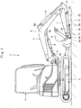
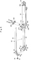
- Figs. 1 to 6 show a first embodiment of a cylinder device according to the present invention.
- the hydraulic excavator 1 is constituted by including an automotive crawler-type lower traveling structure 2, an upper revolving structure 3 rotatably mounted on the lower traveling structure 2, and a swing-type working mechanism 4 provided on a front part side of the upper revolving structure 3.
- the hydraulic excavator 1 is capable of performing an excavating work of earth and sand or the like by the working mechanism 4.
- the swing-type working mechanism 4 is constituted by including a swing post 5 mounted on a front end side of a revolving frame 3A which becomes a base of the upper revolving structure 3, swingably in a left-right direction, a boom 6 mounted on an upper end part of the swing post 5, rotatably in a vertical direction, an arm 7 mounted on a distal end side of the boom 6, rotatably in the vertical direction, and a bucket 8 mounted on a distal end side of the arm 7, rotatably in the vertical direction.
- a cylinder bracket 6A on which a rod of a boom cylinder 9 which will be described later is rotatably mounted is provided on a lower surface side of the boom 6.
- a cylinder bracket 6B on which a tube of an arm cylinder 10 which will be described later is rotatably mounted is provided on an upper surface side of the boom 6.
- a cylinder bracket 7A on which a rod of the arm cylinder 10 and a tube 22 of a bucket cylinder 21 which will be described later are rotatably mounted is provided on a base end part on the boom 6 side in the arm 7.
- a boom cylinder 9 for rotatably driving the boom 6 is provided between the swing post 5 and the cylinder bracket 6A of the boom 6.
- the arm cylinder 10 for rotatably driving the arm 7 is provided between the cylinder bracket 6A of the boom 6 and the cylinder bracket 7A of the arm 7.
- the bucket cylinder 21 which will be described later for rotating/driving the bucket 8 is provided between the cylinder bracket 7A of the arm 7 and a bucket link 11.
- the working mechanism 4 is to perform an excavating work of a gutter or the like in the road, for example, by rotating the boom 6, the arm 7, and the bucket 8 in a state where the swing post 5 is made to swing in the left-right direction by a swing cylinder (not shown).
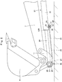
- the bucket cylinder 21 will be described as a typical example of the cylinder device according to this embodiment.
- the bucket cylinder 21 is provided between the arm 7 and the bucket link 11 and is to rotate the bucket 8 with respect to the arm 7.
- This bucket cylinder 21 constitutes the cylinder device of the present invention.
- the bucket cylinder 21 is constituted by including the tube 22, a piston (not shown), a rod 24, a cover guide 28, and a protective cover 34.
- the tube 22 has one side in a length direction closed as a bottom part 22A, while the other side forms a lengthy cylindrical shape (cylindrical shape) as a rod guide 22B.
- a mounting eye (crevice) 23 is integrally provided on the bottom part 22A. As shown in Fig. 1 , the mounting eye 23 is rotatably pin-connected to the cylinder bracket 7A of the arm 7.
- the piston (not shown) is slidably inserted into the tube 22 in an axial direction.
- One side of the rod 24 which will be described later is mounted on this piston.
- the rod 24 has one side mounted to the piston in the tube 22, while the other side protrudes from the rod guide 22B side, capable of extension/contraction.
- a cylindrical boss part 25 forming an outer diameter dimension A is mounted to a protruding end side of the rod 24.
- An inner circumferential side of the boss part 25 is a pin insertion hole 25A extending in an orthogonal direction to an axial direction (extension/contraction direction) of the rod 24.
- the rod 24 is pin-connected with the bucket link 11 by using a pin 26 inserted into the pin insertion hole 25A (see, Fig. 2 ).
- a grease nipple 27 is provided on a distal end side of the rod 24 in an outer periphery 25B of the boss part 25.
- This grease nipple 27 protrudes outward in the radial direction of the boss part 25.
- the grease nipple 27 is mounted in a greasing hole (not shown) drilled toward the pin insertion hole 25A from the outer periphery 25B of the boss part 25.
- the grease nipple 27 is for supplying a lubricant oil such as a grease into the pin insertion hole 25A of the boss part 25.
- the grease nipple 27 protrudes outward in the radial direction of the boss part 25 at a position on a side opposite to the arm 7 in the outer periphery 25B of the boss part 25. Therefore, a grease gun, not shown, can be easily attached to the grease nipple 27, the lubricant oil can be supplied to the pin insertion hole 25A. Further, a protective protrusion 39 which will be described later is provided on the outer periphery 25B of the boss part 25. The grease nipple 27 and the protective protrusion 39 are juxtaposed and provided in the extension/contraction direction of the rod 24.
- the cover guide 28 is provided on the rod guide 22B side in the tube 22. This cover guide 28 is fixed to the tube 22 by welding or the like at a position on the side opposite to the arm 7 in the outer periphery of the tube 22.
- the cover guide 28 is to support the protective cover 34 which will be described later movably in the extension/contraction direction of the rod 24 when the rod 24 is extended/contracted with respect to the tube 22.
- the cover guide 28 is constituted by including a support plate 29, a column 31, and a clamping plate 32.
- the support plate 29 is a plate material having a substantially inverted U-shape extending in an orthogonal direction to the axial direction of the tube 22 and is fixed to the outer periphery of the tube 22 by welding or the like.
- the support plate 29 is fixed to the outer periphery of the tube 22 by welding or the like and is constituted by a pair of leg parts 29A extending outward in the radial direction of the tube 22 and a protective cover support part 29B connecting distal end sides of the leg parts 29A. Through holes (not shown) penetrated in a thickness direction are drilled in both end sides in a longitudinal direction of the protective cover support part 29B.
- back surface 29B1Nuts 30 (only one of them is shown) are fixed to a back surface 29B1 (surface on the tube 22 side) of the protective cover support part 29B by welding or the like at positions corresponding to the through holes, respectively.
- columns 31 are fixed to a front surface 29B2 of the protective cover support part 29B by welding or the like at positions corresponding to the through holes, respectively.
- Each of the columns 31 is formed as a cylindrical body in which a bolt insertion hole 31A is drilled in an inner circumferential side.
- a height dimension of each column 31 has a value larger than a thickness dimension of the protective cover 34 which will be described later.
- a dimension between each of the columns 31 has a value larger than a width dimension of the protective cover 34.
- the clamping plate 32 is a plate material having a substantial U-shape extending in the orthogonal direction to the axial direction of the tube 22 and is faced with the support plate 29 through the column 31.
- the clamping plate 32 supports the protective cover 34 which will be described later by clamping it with the support plate 29.
- Bolt through holes 32A are drilled at positions corresponding to the columns 31 in the clamping plate 32, respectively.
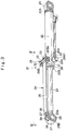
- the protective cover 34 has one side in the length direction supported by the cover guide 28 provided on the tube 22, and has the other side mounted on the boss part 25.
- This protective cover 34 is formed having a lengthy plate shape extending from the tube 22 to the boss part 25.
- the protective cover 34 is disposed on the side opposite to the arm 7 across the rod 24in order to protect the rod 24 from earth and sand and the like. That is, the rod 24 is constituted to be located between the arm 7 and the protective cover 34.
- the protective cover 34 is formed by a resin material having elasticity or a steel plate material having elasticity so as to be able to stand contact with the earth and sand, stones and the like.
- resin material nylon, polycarbonate, ASA resin and the like with strong impact resistance are suitably used, for example.
- steel plate material a spring steel such as a carbon steel, a silicon manganese steel and the like is suitably used, for example.
- the protective cover 34 is constituted by a plate part 35 and a winding part 37.
- the plate part 35 is formed having a lengthy plate shape extending from the cover guide 28 toward the boss part 25. That is, the plate part 35 protects the rod 24 between the cover guide 28 and the boss part 25.
- the plate part 35 is clamped between the support plate 29 of the cover guide 28 and the clamping plate 32 and is supported movably in the extension/contraction direction of the rod 24. That is, the plate part 35 is retained by the cover guide 28 and slides/moves between the support plate 29 of the cover guide 28 and the clamping plate 32 by following the extension/contraction operation of the rod 24.
- the plate part 35 is formed by a resin material or a steel plate material having elasticity. Therefore, the plate part 35 is elastically deformed (flexural deformation) into a recess shape toward the rod 24 side when being brought into contact with earth and sand. As a result, the plate part 35 relaxes an external force by contact with the earth and sand and suppresses the deformation.
- a nipple through hole 36 penetrated in the thickness direction is formed on a distal end side of the plate part 35.
- This nipple through hole 36 is formed at a position corresponding to the grease nipple 27 provided on the boss part 25 and becomes an opening when a nozzle of the grease gun, not shown, is attached to the grease nipple 27.
- the nipple through hole 36 is constituted such that the grease nipple 27 is inserted therein when the earth and sand or the like are brought into contact with the plate part 35, and the plate part 35 is deflected toward the rod 24. As a result, the grease nipple 27 is not brought into contact with the plate part 35 even if the plate part 35 is deflected and thus, the lives of the grease nipple 27 and the plate part 35 can be improved.
- the winding part 37 is formed as an arc-shaped body so as to be wound around the outer periphery 25B of the boss part 25 from the distal end side of the plate part 35. As shown in Fig. 6 , an arc diameter B of the winding part 37 is formed smaller than an outer diameter dimension A of the boss part 25 in a free state (state removed from the boss part 25).
- the winding part 37 is held by having elasticity toward an inner side in the radial direction of the boss part 25 in a state wound around the boss part 25. That is, the winding part 37 is held by the boss part 25 by being fitted in the outer periphery 25B of the boss part 25.
- one side of the plate part 35 in a length direction is supported by the cover guide 28 movably in the extension/contraction direction of the rod 24, while the other side of the plate part 35 is held by the winding part 37 elastically wound around the outer periphery 25B of the boss part 25.
- a protective protrusion engaging hole 38 is penetrated in the thickness direction of the winding part 37 at a position corresponding to the protective protrusion 39 which will be described later provided on the boss part 25.
- This protective protrusion engaging hole 38 is formed by being juxtaposed with the nipple through hole 36 in the extension/contraction direction of the rod 24.
- the protective protrusion engaging hole 38 is formed movably with respect to the protective protrusion 39 by elastic deformation of the protective cover 34.
- the protective protrusion engaging hole 38 is formed as a long hole extending in a circumferential direction of the winding part 37. As shown in Figs. 4 and 6 , a length dimension C of the protective protrusion engaging hole 38 is formed larger than an outer diameter dimension D of the protective protrusion 39. As shown in Figs. 3 and 4 , in a state where the winding part 37 is fitted in the boss part 25, the protective protrusion 39 is located on the base end side (nipple through hole 36 side) of the protective protrusion engaging hole 38.
- the plate part 35 of the protective cover 34 when the earth and sand or the like are brought into contact with the plate part 35 of the protective cover 34, the plate part 35 is elastically deformed (flexural deformation) into a recess shape toward the rod 24 side.
- the winding part 37 is pulled by the deformation and is slidably displaced on the outer periphery 25B of the boss part 25 in the circumferential direction.
- the protective protrusion engaging hole 38 moves to a contraction side in the extension/contraction direction of the rod 24 with respect to the protective protrusion 39.
- concentration of a load to the winding part 37 and the protective protrusion 39 can be suppressed, the life of the protective cover 34 can be improved.
- the protective protrusion 39 is fixed to the outer periphery 25B of the boss part 25 by welding or the like at a position different from the grease nipple 27. This protective protrusion 39 is juxtaposed with the grease nipple 27 in the extension/contraction direction of the rod 24 and is provided on the boss part 25.
- the protective protrusion 39 is formed having a solid columnar body, for example, and protrudes outward in the radial direction of the boss part 25 and protects the boss part 25 and the protective cover 34.
- the protective protrusion 39 is located on the side opposite to the arm 7 across the rod 24 in the outer periphery 25B of the boss part 25 and protrudes outward in the radial direction of the boss part 25. Moreover, the protective protrusion 39 penetrates the protective protrusion engaging hole 38 of the protective cover 34 and protrudes outward from the plate part 35 of the protective cover 34.
- the protective protrusion 39 is brought into contact with the ground surface, whereby the protective cover 34 can be a state not in contact with the ground surface.
- the protective protrusion 39 is first brought into contact with the ground surface. Therefore, the protective cover 34 is in the non-contact state with the ground surface.
- the protective protrusion 39 is provided on the outer periphery 25B of the boss part 25 so that the protective cover 34 can be the non-contact state with the ground surface when the arm 7 of the hydraulic excavator 1 is folded and the boom 6 is lowered.
- the protective protrusion 39 improves the lives of the boss part 25 and the protective cover 34 by bringing the boss part 25 and the protective cover 34 into the non-contact state with the ground surface.
- the bucket cylinder according to the first embodiment has the constitution as described above, and the hydraulic excavator 1 including this bucket cylinder can perform the excavating work of a gutter or the like in a road by causing the swing post 5 to swing in the left-right direction by the swing cylinder (not shown)and by rotating the boom 6, the arm 7, and the bucket 8 by the boom cylinder 9, the arm cylinder 10, and the bucket cylinder 21, respectively, for example.
- the protective cover 34 moves by following the rod 24 while being guided by the cover guide 28.
- the protective cover 34 protects the rod 24 protruding from the rod guide 22B of the tube 22 at all times from the outer periphery side and thus, contact of the rod 24 protruding from the tube 22 with the earth and sand or stones or the like can be prevented.
- the cylinder device described in the aforementioned Patent Document 1 to Patent Document 3 can be used as a bucket cylinder device for rotating the bucket of the hydraulic excavator, for example.
- the hydraulic excavator is parked or the hydraulic excavator is transported or the like, if the arm is folded and the boom is lowered, it leads to a problem that the protective cover is brought into contact with the ground surface and a rear deck of a trailer, which lowers the life of the protective cover.
- the protective cover is formed of an elastic material in order to suppress deformation of the protective cover when earth and sand are brought into contact with the protective cover.
- the support part of the protective cover has complicated constitution in order not to concentrate the load when the protective cover is elastically deformed and has a large number of components, which leads to a problem of a cost increase.
- the cylinder device (bucket cylinder 21) according to the first embodiment has the protective protrusion 39 provided by protruding outward in the radial direction of the boss part 25 on the boss part 25 of the rod 24.
- This protective protrusion 39 penetrates the protective protrusion engaging hole 38 of the protective cover 34 and protrudes outward from the plate part 35 of the protective cover 34. Therefore, when the bucket 8 of the working mechanism 4 is brought closer to the ground surface, and the tube 22 and the rod 24 of the bucket cylinder 21 are brought closer to the ground surface, the protective protrusion 39 is brought into contact with the ground surface, whereby the protective cover 34 and the ground surface can be the non-contact state.
- the protective protrusion 39 is first brought into contact with the ground surface, and the protective cover 34 can be the non-contact state with the ground surface. As a result, since the protective cover 34 is protected by the protective protrusion 39, the life can be improved.
- the protective cover 34 is formed by a material having elasticity. Furthermore, the protective cover 34 is constituted by the plate part 35 extending from the cover guide 28 toward the boss part 25 and the winding part 37 formed as the arc-shaped body so as to be wound around the outer periphery of the boss part 25 from the distal end side of the plate part 35. As shown in Fig. 6 , the arc diameter B of the winding part 37 is formed smaller than the outer diameter dimension A of the boss part 25 in the free state.
- the winding part 37 is held by having elasticity toward the inner side in the radial direction of the boss part 25 in a state wound around the boss part 25. That is, the winding part 37 of the protective cover 34 is held by the boss part 25 by being fitted in the outer periphery 25B of the boss part 25.
- the plate part 35 is supported by the cover guide 28 movably in the extension/contraction direction of the rod 24.
- the protective protrusion engaging hole 38 formed in the protective cover 34 is formed as a long hole extending in the circumferential direction of the winding part 37. That is, the length dimension C of the protective protrusion engaging hole 38 is a dimension larger than the outer diameter dimension D of the protective protrusion 39.
- the protective protrusion 39 is located on the base end side (nipple through hole 36 side) of the protective protrusion engaging hole 38.
- the plate part 35 of the protective cover 34 when earth and sand or the like are brought into contact with the plate part 35 of the protective cover 34, the plate part 35 is elastically deformed (flexural deformation) to a recess shape toward the rod 24 side.
- the winding part 37 is pulled by the deformation and is slidably displaced on the outer periphery 25B of the boss part 25 in the circumferential direction.
- the protective protrusion engaging hole 38 moves to the contraction side in the extension/contraction direction of the rod 24 with respect to the protective protrusion 39.
- concentration of a load to the winding part 37 and the protective protrusion 39 can be suppressed, the life of the protective cover 34 can be improved. That is, since the protective cover 34 can make the winding part 37 rotatable even with the smaller number of components and can suppress concentration of the load by elastic deformation of the plate part 35, the cost can be reduced.
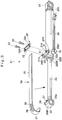
- Figs. 7 and 8 show a second embodiment of the present invention.
- a feature of this embodiment is that a retaining member for retaining the winding part is provided on the boss part.
- the same constituent elements as those in the first embodiment are given the same reference numerals, and the description thereof will be omitted.
- a retaining member 41 is provided at a position different from the protective protrusion 39 in the outer periphery 25B of the boss part 25.
- This retaining member 41 is fixed to the outer periphery 25B of the boss part 25 by welding or the like and retains a winding part 47 which will be described later by protruding outward in the radial direction of the boss part 25.
- the retaining member 41 is constituted by a screw seat 42, a bolt 43, and a washer 44.
- the screw seat 42 is located in the extension/contraction direction of the rod 24 in the outer periphery 25B of the boss part 25 and protrudes outward in the radial direction of the boss part 25.
- the screw seat 42 protrudes toward an extension side in the extension/contraction direction of the rod 24 from the outer periphery 25B of the boss part 25.
- a protective cover 45 is retained by clamping the winding part 47 between the washer 44 and the screw seat 42 by inserting the bolt 43 on which the washer 44 is mounted into a retaining member engaging hole 48, which will be described later, and by screwing the bolt 43 in the screw seat 42.
- the retaining member 41 since the retaining member 41 is located in the extension/contraction direction of the rod 24 and protrudes outward in the radial direction of the boss part 25, the retaining member 41 does not protrude outward from a plate part 46 which will be described later. Therefore, with respect to the retaining member 41, the bolt 43 or the like can be the non-contact state with the ground surface when the arm 7 of the hydraulic excavator 1 is folded and the boom 6 is lowered, for example, stability and a life of the retaining member 41 can be improved.
- the winding part 47 may be held by having elasticity toward an inner side in the radial direction of the boss part 25 similarly to the winding part 37 according to the first embodiment. However, since the winding part 47 is retained by the retaining member 41 with respect to the boss part 25, the winding part 47 does not have to have elasticity toward the inner side in the radial direction of the boss part 25.
- the retaining member engaging hole 48 is formed by being juxtaposed with the protective protrusion engaging hole 38 in the circumferential direction of the winding part 47. This retaining member engaging hole 48 penetrates in the thickness direction of the winding part 47 at a position corresponding to the retaining member 41 provided on the boss part 25.
- the retaining member engaging hole 48 is formed movably with respect to the retaining member 41 by elastic deformation of the protective cover 45.
- the retaining member engaging hole 48 is formed as a long hole extending in the circumferential direction of the winding part 47.
- the retaining member 41 is located on a base end side (protective protrusion engaging hole 38 side) of the retaining member engaging hole 48.
- the plate part 46 is elastically deformed (flexural deformation) into a recess shape toward the rod 24 side.
- the winding part 47 is pulled by the deformation and is slidably displaced on the outer periphery 25B of the boss part 25 in the circumferential direction.
- the retaining member engaging hole 48 moves in the circumferential direction of the boss part 25 with respect to the retaining member 41.
- concentration of a load to the winding part 47 and the retaining member 41 can be suppressed, the life of the protective cover 45 can be improved.
- the protective protrusion 39 is brought into contact with the ground surface at first, and the bolt 43 and the like can be the non-contact state with the ground surface. Therefore, stability and the life of the retaining member 41 can be improved.
- the protective protrusion 39 is a columnar body
- the present invention is not limited to that but the protective projection may be formed by a square columnar body, for example. The same applies to the second embodiment.
- the protective protrusion engaging hole 38 is formed as a long hole extending in the circumferential direction of the winding part 37 is described as an example.
- the present invention is not limited to that, and the protective protrusion engaging hole may be a circular hole having a hole diameter larger than the outer diameter dimension of the protective protrusion. The same applies to the second embodiment.
- the retaining member 41 is constituted by the screw seat 42, the bolt 43, and the washer 44 is described as an example.
- the present invention is not limited to that, and the winding part may be retained by hitting a pin including a washer into a cylinder part having a pin hole, for example.
Landscapes
- Engineering & Computer Science (AREA)
- General Engineering & Computer Science (AREA)
- Mechanical Engineering (AREA)
- Mining & Mineral Resources (AREA)
- Civil Engineering (AREA)
- Structural Engineering (AREA)
- Physics & Mathematics (AREA)
- Fluid Mechanics (AREA)
- Actuator (AREA)
- Component Parts Of Construction Machinery (AREA)
- Earth Drilling (AREA)
Claims (4)
- Machine de chantier (1) comprenant :une structure de déplacement inférieure automotrice (2), une structure de pivotement supérieure (3) montée en rotation sur ladite structure de déplacement inférieure (2), et un mécanisme de travail (4) monté sur une partie avant de ladite structure de pivotement supérieure (3), capable de se déplacer vers le haut/bas,ledit mécanisme de travail (4) inclut une flèche (6) prévue sur ladite structure de pivotement supérieure (3), capable de se déplacer vers le haut/bas, un bras (7) prévu en rotation sur un côté d'extrémité distale de ladite flèche (6), et un godet (8) prévu en rotation sur un côté d'extrémité distale dudit bras (7),un vérin de godet (21) est prévu entre ledit bras (7) et ledit godet (8) pour faire tourner ledit godet (8), dans laquelle ledit vérin de godet (21) inclut :un tube (22) ayant une forme cylindrique allongée dans lequel un côté dans une direction de la longueur est fermé à titre de partie de fond (22A), tandis que l'autre côté est un guide de tige (22B) ;une tige (24) ayant un côté monté sur un piston dans ledit tube (22) et l'autre côté en projection capable de s'étendre/se rétracter depuis ledit côté de guide de tige (22B) et ayant une partie en bossage cylindrique (25) montée sur un côté d'extrémité en projection ; etun cache de protection en forme de plaque allongée (45) ayant un côté dans la direction de la longueur supporté par un guide de cache (28) prévu sur ledit tube (22) afin de protéger ladite tige (24), et ayant l'autre côté monté sur ladite partie en bossage (25),caractérisé en ce que :ledit cache de protection (45) est formé en ayant une forme de plaque par un matériau présentant une élasticité, et ledit cache de protection (45) est constitué d'une partie formant plaque (46) protégeant ladite tige (24) entre ledit guide de cache (28) et ladite partie en bossage (25) et d'une partie d'enroulement (47) formée en ayant un corps en forme d'arc de manière à être enroulée autour d'une périphérie extérieure de ladite partie en bossage (25) depuis un côté d'extrémité distale de ladite partie formant plaque (46) ;une projection de protection (39) se projetant vers l'extérieur dans une direction radiale de ladite partie en bossage (25) est prévue sur la périphérie extérieure de ladite partie en bossage (25) ;un trou d'engagement de projection de protection (38), à l'intérieur duquel ladite projection de protection (39) est engagée, est prévu dans ladite partie d'enroulement (47) à une position correspondant à ladite projection de protection (39) ;un élément de retenue (41), se projetant vers un côté extérieur dans une direction radiale de ladite partie en bossage (25) à une position différente de ladite projection de protection (39) et retenant ladite partie d'enroulement (47), est prévu sur ladite partie en bossage (25) ;un trou d'engagement d'élément de retenue (48), à l'intérieur duquel ledit élément de retenue (41) est engagé, est prévu dans ladite partie d'enroulement (47) à une position correspondant audit élément de retenue (41), etladite projection de protection (39) est agencée de sorte que, quand ledit tube (22) et ladite tige (24) dudit vérin de godet (21) sont rapprochés d'une surface du sol en amenant ledit godet (8) dudit mécanisme de travail (4) plus près de la surface du sol, ladite projection de protection (39) pénètre dans ledit trou d'engagement de projection de protection (38) dudit cache de protection (45) et se projette vers l'extérieur depuis ledit cache de projection (45) de sorte que ladite projection de protection (39) vient en contact avec la surface du sol.
- Machine de chantier (1) selon la revendication 1, dans laquelle un diamètre d'arc (B) de ladite partie d'enroulement (47) est formé avec une dimension inférieure à une dimension d'un diamètre extérieur (A) de ladite partie en bossage (25) dans un état libre ; et
ladite partie d'enroulement (47) est maintenue en ayant une élasticité vers un côté intérieur dans une direction radiale de ladite partie en bossage (25) dans un état enroulé autour de ladite partie en bossage (25). - Machine de chantier (1) selon la revendication 1, dans laquelle ledit trou d'engagement de projection de protection (38) est formé de manière mobile par rapport à ladite projection de protection (39) par déformation élastique dudit cache de protection (45).
- Machine de chantier (1) selon la revendication 1, dans laquelle ledit trou d'engagement d'élément de retenue (48) est formé de manière mobile par rapport audit élément de retenue (41) par déformation élastique dudit cache de protection (45).
Applications Claiming Priority (2)
| Application Number | Priority Date | Filing Date | Title |
|---|---|---|---|
| JP2015179382A JP6509693B2 (ja) | 2015-09-11 | 2015-09-11 | シリンダ装置 |
| PCT/JP2016/054841 WO2017043100A1 (fr) | 2015-09-11 | 2016-02-19 | Dispositif de vérin |
Publications (3)
| Publication Number | Publication Date |
|---|---|
| EP3348714A1 EP3348714A1 (fr) | 2018-07-18 |
| EP3348714A4 EP3348714A4 (fr) | 2019-04-17 |
| EP3348714B1 true EP3348714B1 (fr) | 2020-06-24 |
Family
ID=58239529
Family Applications (1)
| Application Number | Title | Priority Date | Filing Date |
|---|---|---|---|
| EP16843966.9A Not-in-force EP3348714B1 (fr) | 2015-09-11 | 2016-02-19 | Dispositif de vérin |
Country Status (6)
| Country | Link |
|---|---|
| US (1) | US10392783B2 (fr) |
| EP (1) | EP3348714B1 (fr) |
| JP (1) | JP6509693B2 (fr) |
| KR (1) | KR101970263B1 (fr) |
| CN (1) | CN107407069B (fr) |
| WO (1) | WO2017043100A1 (fr) |
Families Citing this family (12)
| Publication number | Priority date | Publication date | Assignee | Title |
|---|---|---|---|---|
| FR3035099A1 (fr) * | 2015-04-18 | 2016-10-21 | Haulotte Group | Nacelle elevatrice a protection contre les nids de poule |
| DE102018110289A1 (de) * | 2018-04-27 | 2019-10-31 | Wacker Neuson Linz Gmbh | Hydraulische kolben-/zylindereinheit mit einer schutzvorrichtung für eine kolbenstange sowie arbeitsfahrzeug damit |
| US10844578B2 (en) | 2018-10-24 | 2020-11-24 | Caterpillar Inc. | Cylinder protection device |
| CN112536140B (zh) * | 2019-06-05 | 2022-05-17 | 浙江厚达智能科技股份有限公司 | 取出中药饮片时不需要倾倒捣药桶的中药捣碎机构 |
| JP7308412B2 (ja) * | 2019-10-15 | 2023-07-14 | パナソニックIpマネジメント株式会社 | 接続装置 |
| JP7308413B2 (ja) * | 2019-10-15 | 2023-07-14 | パナソニックIpマネジメント株式会社 | 接続装置 |
| EP4048917B1 (fr) * | 2019-10-25 | 2024-09-25 | Chromeguard Pty Ltd | Système de protection de tige de piston de cylindre hydraulique |
| DE202020102779U1 (de) | 2020-05-15 | 2021-08-17 | Liebherr-Hydraulikbagger Gmbh | Kolben-Zylinder-Einheit mit Kolbenstangenschutz |
| JP7339469B2 (ja) * | 2021-03-31 | 2023-09-05 | 日立建機株式会社 | 建設機械 |
| EP4455408A4 (fr) * | 2021-12-24 | 2025-11-19 | Kyungwontech Co Ltd | Appareil d'excavation |
| KR102827902B1 (ko) * | 2022-04-06 | 2025-07-01 | 주식회사 경원테크 | 굴삭 장치 |
| WO2024005040A1 (fr) * | 2022-06-30 | 2024-01-04 | 株式会社クボタ | Couvercle de vérin, vérin hydraulique et engin de chantier |
Family Cites Families (8)
| Publication number | Priority date | Publication date | Assignee | Title |
|---|---|---|---|---|
| JPS5320640Y2 (fr) * | 1973-07-17 | 1978-05-30 | ||
| JPH0236604A (ja) * | 1988-07-26 | 1990-02-06 | Mitsubishi Electric Corp | アンテナ装置 |
| JPH0236604U (fr) * | 1988-08-31 | 1990-03-09 | ||
| JPH0512708U (ja) | 1991-08-01 | 1993-02-19 | 油谷重工株式会社 | 建設機械のシリンダガード装置 |
| JP4038197B2 (ja) * | 2004-07-01 | 2008-01-23 | ヤンマー株式会社 | シリンダの保護装置 |
| JP4542019B2 (ja) * | 2005-10-14 | 2010-09-08 | 日立建機株式会社 | シリンダ装置 |
| KR101068208B1 (ko) * | 2009-11-30 | 2011-09-28 | 대모 엔지니어링 주식회사 | 머트리얼 핸들러 작동용 암실린더의 피스톤로드 보호커버 |
| JP5526106B2 (ja) * | 2011-11-08 | 2014-06-18 | 日立建機株式会社 | 建設機械のシリンダカバー取り付け構造 |
-
2015
- 2015-09-11 JP JP2015179382A patent/JP6509693B2/ja not_active Expired - Fee Related
-
2016
- 2016-02-19 WO PCT/JP2016/054841 patent/WO2017043100A1/fr not_active Ceased
- 2016-02-19 CN CN201680012691.4A patent/CN107407069B/zh not_active Expired - Fee Related
- 2016-02-19 EP EP16843966.9A patent/EP3348714B1/fr not_active Not-in-force
- 2016-02-19 US US15/555,149 patent/US10392783B2/en not_active Expired - Fee Related
- 2016-02-19 KR KR1020177023779A patent/KR101970263B1/ko not_active Expired - Fee Related
Non-Patent Citations (1)
| Title |
|---|
| None * |
Also Published As
| Publication number | Publication date |
|---|---|
| EP3348714A1 (fr) | 2018-07-18 |
| EP3348714A4 (fr) | 2019-04-17 |
| JP6509693B2 (ja) | 2019-05-08 |
| KR101970263B1 (ko) | 2019-04-18 |
| KR20170110639A (ko) | 2017-10-11 |
| WO2017043100A1 (fr) | 2017-03-16 |
| CN107407069A (zh) | 2017-11-28 |
| CN107407069B (zh) | 2020-01-17 |
| US20180044892A1 (en) | 2018-02-15 |
| JP2017053174A (ja) | 2017-03-16 |
| US10392783B2 (en) | 2019-08-27 |
Similar Documents
| Publication | Publication Date | Title |
|---|---|---|
| EP3348714B1 (fr) | Dispositif de vérin | |
| US8920105B2 (en) | Rotation-type construction machine | |
| KR20180099358A (ko) | 건설기계의 캐빈 조립체 | |
| KR20130135246A (ko) | 건설장비용 전복방지구조 캡 | |
| JP2006016854A (ja) | シリンダの保護装置 | |
| US5383563A (en) | Outrigger and guard assembly | |
| KR101527222B1 (ko) | 시트베이스 슬라이딩 장치 | |
| JP5526106B2 (ja) | 建設機械のシリンダカバー取り付け構造 | |
| EP1982948A2 (fr) | Tampon glissant pour flèche | |
| EP3022073A1 (fr) | Amortisseur de choc pour engin à chenilles | |
| EP3178679A1 (fr) | Véhicule de travail, procédé de fonctionnement et procédé d'assemblage d'un appareil de remorquage | |
| US20150233090A1 (en) | Turret assembly for machines | |
| KR101061697B1 (ko) | 유압 실린더의 커버 장치 | |
| WO2020053892A1 (fr) | Ensemble pare-chocs avant permettant de monter un siège, un moyen de lestage et une structure ajoutée dans un véhicule | |
| JP2009107540A (ja) | 位置調整式ステアリング装置 | |
| JP6959208B2 (ja) | ホイール式建設機械 | |
| JP2019051795A (ja) | ホイール式建設機械 | |
| KR101195739B1 (ko) | 자동차의 조향장치 | |
| JP6390061B2 (ja) | 梯子機構 | |
| JP3712042B2 (ja) | 作業台 | |
| JP4809285B2 (ja) | 走行車両のロプス装置 | |
| EP1867792B1 (fr) | Stabilisateur | |
| KR20070060789A (ko) | 쇼바결합용 가이드장치 | |
| JP2006160151A (ja) | 産業車両用シリンダカバー及び産業車両 | |
| KR20150045054A (ko) | 풋 스텝을 구비하는 건설기계 |
Legal Events
| Date | Code | Title | Description |
|---|---|---|---|
| STAA | Information on the status of an ep patent application or granted ep patent |
Free format text: STATUS: THE INTERNATIONAL PUBLICATION HAS BEEN MADE |
|
| PUAI | Public reference made under article 153(3) epc to a published international application that has entered the european phase |
Free format text: ORIGINAL CODE: 0009012 |
|
| STAA | Information on the status of an ep patent application or granted ep patent |
Free format text: STATUS: REQUEST FOR EXAMINATION WAS MADE |
|
| 17P | Request for examination filed |
Effective date: 20180222 |
|
| AK | Designated contracting states |
Kind code of ref document: A1 Designated state(s): AL AT BE BG CH CY CZ DE DK EE ES FI FR GB GR HR HU IE IS IT LI LT LU LV MC MK MT NL NO PL PT RO RS SE SI SK SM TR |
|
| AX | Request for extension of the european patent |
Extension state: BA ME |
|
| DAV | Request for validation of the european patent (deleted) | ||
| DAX | Request for extension of the european patent (deleted) | ||
| REG | Reference to a national code |
Ref country code: DE Ref legal event code: R079 Ref document number: 602016038887 Country of ref document: DE Free format text: PREVIOUS MAIN CLASS: E02F0009000000 Ipc: E02F0009220000 |
|
| A4 | Supplementary search report drawn up and despatched |
Effective date: 20190315 |
|
| RIC1 | Information provided on ipc code assigned before grant |
Ipc: E02F 9/22 20060101AFI20190311BHEP Ipc: F15B 15/14 20060101ALI20190311BHEP |
|
| GRAP | Despatch of communication of intention to grant a patent |
Free format text: ORIGINAL CODE: EPIDOSNIGR1 |
|
| STAA | Information on the status of an ep patent application or granted ep patent |
Free format text: STATUS: GRANT OF PATENT IS INTENDED |
|
| INTG | Intention to grant announced |
Effective date: 20200107 |
|
| GRAS | Grant fee paid |
Free format text: ORIGINAL CODE: EPIDOSNIGR3 |
|
| GRAA | (expected) grant |
Free format text: ORIGINAL CODE: 0009210 |
|
| STAA | Information on the status of an ep patent application or granted ep patent |
Free format text: STATUS: THE PATENT HAS BEEN GRANTED |
|
| AK | Designated contracting states |
Kind code of ref document: B1 Designated state(s): AL AT BE BG CH CY CZ DE DK EE ES FI FR GB GR HR HU IE IS IT LI LT LU LV MC MK MT NL NO PL PT RO RS SE SI SK SM TR |
|
| REG | Reference to a national code |
Ref country code: GB Ref legal event code: FG4D |
|
| REG | Reference to a national code |
Ref country code: CH Ref legal event code: EP |
|
| REG | Reference to a national code |
Ref country code: DE Ref legal event code: R096 Ref document number: 602016038887 Country of ref document: DE |
|
| REG | Reference to a national code |
Ref country code: AT Ref legal event code: REF Ref document number: 1284027 Country of ref document: AT Kind code of ref document: T Effective date: 20200715 |
|
| REG | Reference to a national code |
Ref country code: IE Ref legal event code: FG4D |
|
| PG25 | Lapsed in a contracting state [announced via postgrant information from national office to epo] |
Ref country code: SE Free format text: LAPSE BECAUSE OF FAILURE TO SUBMIT A TRANSLATION OF THE DESCRIPTION OR TO PAY THE FEE WITHIN THE PRESCRIBED TIME-LIMIT Effective date: 20200624 Ref country code: GR Free format text: LAPSE BECAUSE OF FAILURE TO SUBMIT A TRANSLATION OF THE DESCRIPTION OR TO PAY THE FEE WITHIN THE PRESCRIBED TIME-LIMIT Effective date: 20200925 Ref country code: NO Free format text: LAPSE BECAUSE OF FAILURE TO SUBMIT A TRANSLATION OF THE DESCRIPTION OR TO PAY THE FEE WITHIN THE PRESCRIBED TIME-LIMIT Effective date: 20200924 Ref country code: FI Free format text: LAPSE BECAUSE OF FAILURE TO SUBMIT A TRANSLATION OF THE DESCRIPTION OR TO PAY THE FEE WITHIN THE PRESCRIBED TIME-LIMIT Effective date: 20200624 Ref country code: LT Free format text: LAPSE BECAUSE OF FAILURE TO SUBMIT A TRANSLATION OF THE DESCRIPTION OR TO PAY THE FEE WITHIN THE PRESCRIBED TIME-LIMIT Effective date: 20200624 |
|
| REG | Reference to a national code |
Ref country code: LT Ref legal event code: MG4D |
|
| PG25 | Lapsed in a contracting state [announced via postgrant information from national office to epo] |
Ref country code: BG Free format text: LAPSE BECAUSE OF FAILURE TO SUBMIT A TRANSLATION OF THE DESCRIPTION OR TO PAY THE FEE WITHIN THE PRESCRIBED TIME-LIMIT Effective date: 20200924 Ref country code: HR Free format text: LAPSE BECAUSE OF FAILURE TO SUBMIT A TRANSLATION OF THE DESCRIPTION OR TO PAY THE FEE WITHIN THE PRESCRIBED TIME-LIMIT Effective date: 20200624 Ref country code: RS Free format text: LAPSE BECAUSE OF FAILURE TO SUBMIT A TRANSLATION OF THE DESCRIPTION OR TO PAY THE FEE WITHIN THE PRESCRIBED TIME-LIMIT Effective date: 20200624 Ref country code: LV Free format text: LAPSE BECAUSE OF FAILURE TO SUBMIT A TRANSLATION OF THE DESCRIPTION OR TO PAY THE FEE WITHIN THE PRESCRIBED TIME-LIMIT Effective date: 20200624 |
|
| REG | Reference to a national code |
Ref country code: NL Ref legal event code: MP Effective date: 20200624 |
|
| REG | Reference to a national code |
Ref country code: AT Ref legal event code: MK05 Ref document number: 1284027 Country of ref document: AT Kind code of ref document: T Effective date: 20200624 |
|
| PG25 | Lapsed in a contracting state [announced via postgrant information from national office to epo] |
Ref country code: AL Free format text: LAPSE BECAUSE OF FAILURE TO SUBMIT A TRANSLATION OF THE DESCRIPTION OR TO PAY THE FEE WITHIN THE PRESCRIBED TIME-LIMIT Effective date: 20200624 Ref country code: NL Free format text: LAPSE BECAUSE OF FAILURE TO SUBMIT A TRANSLATION OF THE DESCRIPTION OR TO PAY THE FEE WITHIN THE PRESCRIBED TIME-LIMIT Effective date: 20200624 |
|
| PG25 | Lapsed in a contracting state [announced via postgrant information from national office to epo] |
Ref country code: CZ Free format text: LAPSE BECAUSE OF FAILURE TO SUBMIT A TRANSLATION OF THE DESCRIPTION OR TO PAY THE FEE WITHIN THE PRESCRIBED TIME-LIMIT Effective date: 20200624 Ref country code: RO Free format text: LAPSE BECAUSE OF FAILURE TO SUBMIT A TRANSLATION OF THE DESCRIPTION OR TO PAY THE FEE WITHIN THE PRESCRIBED TIME-LIMIT Effective date: 20200624 Ref country code: ES Free format text: LAPSE BECAUSE OF FAILURE TO SUBMIT A TRANSLATION OF THE DESCRIPTION OR TO PAY THE FEE WITHIN THE PRESCRIBED TIME-LIMIT Effective date: 20200624 Ref country code: AT Free format text: LAPSE BECAUSE OF FAILURE TO SUBMIT A TRANSLATION OF THE DESCRIPTION OR TO PAY THE FEE WITHIN THE PRESCRIBED TIME-LIMIT Effective date: 20200624 Ref country code: EE Free format text: LAPSE BECAUSE OF FAILURE TO SUBMIT A TRANSLATION OF THE DESCRIPTION OR TO PAY THE FEE WITHIN THE PRESCRIBED TIME-LIMIT Effective date: 20200624 Ref country code: SM Free format text: LAPSE BECAUSE OF FAILURE TO SUBMIT A TRANSLATION OF THE DESCRIPTION OR TO PAY THE FEE WITHIN THE PRESCRIBED TIME-LIMIT Effective date: 20200624 Ref country code: IT Free format text: LAPSE BECAUSE OF FAILURE TO SUBMIT A TRANSLATION OF THE DESCRIPTION OR TO PAY THE FEE WITHIN THE PRESCRIBED TIME-LIMIT Effective date: 20200624 Ref country code: PT Free format text: LAPSE BECAUSE OF FAILURE TO SUBMIT A TRANSLATION OF THE DESCRIPTION OR TO PAY THE FEE WITHIN THE PRESCRIBED TIME-LIMIT Effective date: 20201026 |
|
| PG25 | Lapsed in a contracting state [announced via postgrant information from national office to epo] |
Ref country code: IS Free format text: LAPSE BECAUSE OF FAILURE TO SUBMIT A TRANSLATION OF THE DESCRIPTION OR TO PAY THE FEE WITHIN THE PRESCRIBED TIME-LIMIT Effective date: 20201024 Ref country code: PL Free format text: LAPSE BECAUSE OF FAILURE TO SUBMIT A TRANSLATION OF THE DESCRIPTION OR TO PAY THE FEE WITHIN THE PRESCRIBED TIME-LIMIT Effective date: 20200624 Ref country code: SK Free format text: LAPSE BECAUSE OF FAILURE TO SUBMIT A TRANSLATION OF THE DESCRIPTION OR TO PAY THE FEE WITHIN THE PRESCRIBED TIME-LIMIT Effective date: 20200624 |
|
| REG | Reference to a national code |
Ref country code: DE Ref legal event code: R097 Ref document number: 602016038887 Country of ref document: DE |
|
| PG25 | Lapsed in a contracting state [announced via postgrant information from national office to epo] |
Ref country code: DK Free format text: LAPSE BECAUSE OF FAILURE TO SUBMIT A TRANSLATION OF THE DESCRIPTION OR TO PAY THE FEE WITHIN THE PRESCRIBED TIME-LIMIT Effective date: 20200624 |
|
| PLBE | No opposition filed within time limit |
Free format text: ORIGINAL CODE: 0009261 |
|
| STAA | Information on the status of an ep patent application or granted ep patent |
Free format text: STATUS: NO OPPOSITION FILED WITHIN TIME LIMIT |
|
| 26N | No opposition filed |
Effective date: 20210325 |
|
| PG25 | Lapsed in a contracting state [announced via postgrant information from national office to epo] |
Ref country code: SI Free format text: LAPSE BECAUSE OF FAILURE TO SUBMIT A TRANSLATION OF THE DESCRIPTION OR TO PAY THE FEE WITHIN THE PRESCRIBED TIME-LIMIT Effective date: 20200624 |
|
| PG25 | Lapsed in a contracting state [announced via postgrant information from national office to epo] |
Ref country code: MC Free format text: LAPSE BECAUSE OF FAILURE TO SUBMIT A TRANSLATION OF THE DESCRIPTION OR TO PAY THE FEE WITHIN THE PRESCRIBED TIME-LIMIT Effective date: 20200624 |
|
| REG | Reference to a national code |
Ref country code: BE Ref legal event code: MM Effective date: 20210228 |
|
| PG25 | Lapsed in a contracting state [announced via postgrant information from national office to epo] |
Ref country code: LI Free format text: LAPSE BECAUSE OF NON-PAYMENT OF DUE FEES Effective date: 20210228 Ref country code: LU Free format text: LAPSE BECAUSE OF NON-PAYMENT OF DUE FEES Effective date: 20210219 Ref country code: CH Free format text: LAPSE BECAUSE OF NON-PAYMENT OF DUE FEES Effective date: 20210228 |
|
| PG25 | Lapsed in a contracting state [announced via postgrant information from national office to epo] |
Ref country code: IE Free format text: LAPSE BECAUSE OF NON-PAYMENT OF DUE FEES Effective date: 20210219 |
|
| PGFP | Annual fee paid to national office [announced via postgrant information from national office to epo] |
Ref country code: GB Payment date: 20211231 Year of fee payment: 7 |
|
| PGFP | Annual fee paid to national office [announced via postgrant information from national office to epo] |
Ref country code: DE Payment date: 20211230 Year of fee payment: 7 |
|
| PGFP | Annual fee paid to national office [announced via postgrant information from national office to epo] |
Ref country code: FR Payment date: 20220118 Year of fee payment: 7 |
|
| PG25 | Lapsed in a contracting state [announced via postgrant information from national office to epo] |
Ref country code: BE Free format text: LAPSE BECAUSE OF NON-PAYMENT OF DUE FEES Effective date: 20210228 |
|
| PG25 | Lapsed in a contracting state [announced via postgrant information from national office to epo] |
Ref country code: CY Free format text: LAPSE BECAUSE OF FAILURE TO SUBMIT A TRANSLATION OF THE DESCRIPTION OR TO PAY THE FEE WITHIN THE PRESCRIBED TIME-LIMIT Effective date: 20200624 |
|
| PG25 | Lapsed in a contracting state [announced via postgrant information from national office to epo] |
Ref country code: HU Free format text: LAPSE BECAUSE OF FAILURE TO SUBMIT A TRANSLATION OF THE DESCRIPTION OR TO PAY THE FEE WITHIN THE PRESCRIBED TIME-LIMIT; INVALID AB INITIO Effective date: 20160219 |
|
| REG | Reference to a national code |
Ref country code: DE Ref legal event code: R119 Ref document number: 602016038887 Country of ref document: DE |
|
| GBPC | Gb: european patent ceased through non-payment of renewal fee |
Effective date: 20230219 |
|
| PG25 | Lapsed in a contracting state [announced via postgrant information from national office to epo] |
Ref country code: GB Free format text: LAPSE BECAUSE OF NON-PAYMENT OF DUE FEES Effective date: 20230219 |
|
| PG25 | Lapsed in a contracting state [announced via postgrant information from national office to epo] |
Ref country code: GB Free format text: LAPSE BECAUSE OF NON-PAYMENT OF DUE FEES Effective date: 20230219 Ref country code: FR Free format text: LAPSE BECAUSE OF NON-PAYMENT OF DUE FEES Effective date: 20230228 Ref country code: DE Free format text: LAPSE BECAUSE OF NON-PAYMENT OF DUE FEES Effective date: 20230901 |
|
| PG25 | Lapsed in a contracting state [announced via postgrant information from national office to epo] |
Ref country code: MK Free format text: LAPSE BECAUSE OF FAILURE TO SUBMIT A TRANSLATION OF THE DESCRIPTION OR TO PAY THE FEE WITHIN THE PRESCRIBED TIME-LIMIT Effective date: 20200624 |
|
| PG25 | Lapsed in a contracting state [announced via postgrant information from national office to epo] |
Ref country code: TR Free format text: LAPSE BECAUSE OF FAILURE TO SUBMIT A TRANSLATION OF THE DESCRIPTION OR TO PAY THE FEE WITHIN THE PRESCRIBED TIME-LIMIT Effective date: 20200624 |
|
| PG25 | Lapsed in a contracting state [announced via postgrant information from national office to epo] |
Ref country code: MT Free format text: LAPSE BECAUSE OF FAILURE TO SUBMIT A TRANSLATION OF THE DESCRIPTION OR TO PAY THE FEE WITHIN THE PRESCRIBED TIME-LIMIT Effective date: 20200624 |