EP3348792A1 - Ensemble d'étanchéité pour composants de moteur de turbine à gaz - Google Patents
Ensemble d'étanchéité pour composants de moteur de turbine à gaz Download PDFInfo
- Publication number
- EP3348792A1 EP3348792A1 EP17206340.6A EP17206340A EP3348792A1 EP 3348792 A1 EP3348792 A1 EP 3348792A1 EP 17206340 A EP17206340 A EP 17206340A EP 3348792 A1 EP3348792 A1 EP 3348792A1
- Authority
- EP
- European Patent Office
- Prior art keywords
- seal
- strip
- gas turbine
- turbine engine
- component
- Prior art date
- Legal status (The legal status is an assumption and is not a legal conclusion. Google has not performed a legal analysis and makes no representation as to the accuracy of the status listed.)
- Granted
Links
Images


Classifications
-
- F—MECHANICAL ENGINEERING; LIGHTING; HEATING; WEAPONS; BLASTING
- F01—MACHINES OR ENGINES IN GENERAL; ENGINE PLANTS IN GENERAL; STEAM ENGINES
- F01D—NON-POSITIVE DISPLACEMENT MACHINES OR ENGINES, e.g. STEAM TURBINES
- F01D11/00—Preventing or minimising internal leakage of working-fluid, e.g. between stages
- F01D11/005—Sealing means between non relatively rotating elements
-
- F—MECHANICAL ENGINEERING; LIGHTING; HEATING; WEAPONS; BLASTING
- F01—MACHINES OR ENGINES IN GENERAL; ENGINE PLANTS IN GENERAL; STEAM ENGINES
- F01D—NON-POSITIVE DISPLACEMENT MACHINES OR ENGINES, e.g. STEAM TURBINES
- F01D25/00—Component parts, details, or accessories, not provided for in, or of interest apart from, other groups
- F01D25/24—Casings; Casing parts, e.g. diaphragms, casing fastenings
-
- F—MECHANICAL ENGINEERING; LIGHTING; HEATING; WEAPONS; BLASTING
- F01—MACHINES OR ENGINES IN GENERAL; ENGINE PLANTS IN GENERAL; STEAM ENGINES
- F01D—NON-POSITIVE DISPLACEMENT MACHINES OR ENGINES, e.g. STEAM TURBINES
- F01D9/00—Stators
- F01D9/02—Nozzles; Nozzle boxes; Stator blades; Guide conduits, e.g. individual nozzles
- F01D9/04—Nozzles; Nozzle boxes; Stator blades; Guide conduits, e.g. individual nozzles forming ring or sector
-
- F—MECHANICAL ENGINEERING; LIGHTING; HEATING; WEAPONS; BLASTING
- F16—ENGINEERING ELEMENTS AND UNITS; GENERAL MEASURES FOR PRODUCING AND MAINTAINING EFFECTIVE FUNCTIONING OF MACHINES OR INSTALLATIONS; THERMAL INSULATION IN GENERAL
- F16J—PISTONS; CYLINDERS; SEALINGS
- F16J15/00—Sealings
- F16J15/02—Sealings between relatively-stationary surfaces
- F16J15/06—Sealings between relatively-stationary surfaces with solid packing compressed between sealing surfaces
- F16J15/062—Sealings between relatively-stationary surfaces with solid packing compressed between sealing surfaces characterised by the geometry of the seat
-
- F—MECHANICAL ENGINEERING; LIGHTING; HEATING; WEAPONS; BLASTING
- F01—MACHINES OR ENGINES IN GENERAL; ENGINE PLANTS IN GENERAL; STEAM ENGINES
- F01D—NON-POSITIVE DISPLACEMENT MACHINES OR ENGINES, e.g. STEAM TURBINES
- F01D25/00—Component parts, details, or accessories, not provided for in, or of interest apart from, other groups
- F01D25/24—Casings; Casing parts, e.g. diaphragms, casing fastenings
- F01D25/246—Fastening of diaphragms or stator-rings
-
- F—MECHANICAL ENGINEERING; LIGHTING; HEATING; WEAPONS; BLASTING
- F05—INDEXING SCHEMES RELATING TO ENGINES OR PUMPS IN VARIOUS SUBCLASSES OF CLASSES F01-F04
- F05D—INDEXING SCHEME FOR ASPECTS RELATING TO NON-POSITIVE-DISPLACEMENT MACHINES OR ENGINES, GAS-TURBINES OR JET-PROPULSION PLANTS
- F05D2240/00—Components
- F05D2240/10—Stators
- F05D2240/11—Shroud seal segments
-
- F—MECHANICAL ENGINEERING; LIGHTING; HEATING; WEAPONS; BLASTING
- F05—INDEXING SCHEMES RELATING TO ENGINES OR PUMPS IN VARIOUS SUBCLASSES OF CLASSES F01-F04
- F05D—INDEXING SCHEME FOR ASPECTS RELATING TO NON-POSITIVE-DISPLACEMENT MACHINES OR ENGINES, GAS-TURBINES OR JET-PROPULSION PLANTS
- F05D2240/00—Components
- F05D2240/55—Seals
-
- F—MECHANICAL ENGINEERING; LIGHTING; HEATING; WEAPONS; BLASTING
- F05—INDEXING SCHEMES RELATING TO ENGINES OR PUMPS IN VARIOUS SUBCLASSES OF CLASSES F01-F04
- F05D—INDEXING SCHEME FOR ASPECTS RELATING TO NON-POSITIVE-DISPLACEMENT MACHINES OR ENGINES, GAS-TURBINES OR JET-PROPULSION PLANTS
- F05D2300/00—Materials; Properties thereof
- F05D2300/60—Properties or characteristics given to material by treatment or manufacturing
- F05D2300/603—Composites; e.g. fibre-reinforced
- F05D2300/6033—Ceramic matrix composites [CMC]
-
- Y—GENERAL TAGGING OF NEW TECHNOLOGICAL DEVELOPMENTS; GENERAL TAGGING OF CROSS-SECTIONAL TECHNOLOGIES SPANNING OVER SEVERAL SECTIONS OF THE IPC; TECHNICAL SUBJECTS COVERED BY FORMER USPC CROSS-REFERENCE ART COLLECTIONS [XRACs] AND DIGESTS
- Y02—TECHNOLOGIES OR APPLICATIONS FOR MITIGATION OR ADAPTATION AGAINST CLIMATE CHANGE
- Y02T—CLIMATE CHANGE MITIGATION TECHNOLOGIES RELATED TO TRANSPORTATION
- Y02T50/00—Aeronautics or air transport
- Y02T50/60—Efficient propulsion technologies, e.g. for aircraft
Definitions
- the present disclosure relates generally to gas turbine engines, and more specifically to seals used in gas turbine engines.
- Gas turbine engines are used to power aircraft, watercraft, power generators, and the like. Adjacent components in a gas turbine engine are often separated by a small gap sometimes called a split line.
- the small gap allows for variations in manufacturing tolerance of the adjacent components and for expansion/contraction of the components that occurs during operation of the gas turbine engine.
- the small gaps between adjacent components may be sealed to prevent the leakage of air through the small gaps during operation of the turbine engine.
- the present disclosure may comprise one or more of the following features and combinations thereof.
- a gas turbine engine assembly may include a first component, a second component, and a seal assembly.
- the first component may comprise ceramic matrix materials.
- the first component may include a first panel formed to include a first chamfer surface and a first attachment feature that extends from the first panel to mount the first panel relative to other components within the gas turbine engine assembly.
- the second component may comprise ceramic matrix materials.
- the second component may include a second panel formed to include a second chamfer surface and a second attachment feature that extends from the second panel to mount the second panel relative to other components within the gas turbine engine assembly.
- the second component may be circumferentially spaced apart from the first component about a center axis of the gas turbine engine assembly to form a gap therebetween.
- the seal assembly may be arranged between the first component and the second component to block gases from passing through the gap.
- the seal assembly may include a first strip seal and a rod seal.
- the first strip seal may extend circumferentially into the first attachment feature and the second attachment feature to block gases from passing between the first attachment feature and the second attachment feature.
- the rod seal may be arranged in a channel formed by the first chamfer surface and the second chamfer surface to block gases from passing between the first panel and the second panel.
- the first strip seal may be interlocked with the rod seal for radial movement therewith to block gases from passing between the rod seal and the first strip seal.
- the rod seal may include a body and a first hook arm.
- the body may extend axially relative to the center axis.
- the first hook arm may extend away from the body to form a first slot between the body and the first hook arm.
- a portion of the first strip seal may extend into the first slot to interlock the first strip seal and the rod seal.
- the first strip seal may include a radially extending seal strip and a leg that extends axially away from the seal strip. The leg may extend into the first slot to interlock the first strip seal with the rod seal.
- the leg of the first strip seal may be spaced apart from at least one of the body and the first hook arm of the rod seal to allow for thermal growth between the first strip seal and the rod seal during use of the gas turbine engine assembly.
- the seal strip may have a width
- the leg may have a width
- the rod seal may have a width in a circumferentially direction. The width of the seal strip may be greater than the width of the rod and the width of the leg.
- the gas turbine engine assembly may further include a second strip seal that includes a radially extending seal strip and a leg that extends axially away from the seal strip of the second strip seal.
- the rod seal may further include a second hook arm that extends away from the body of the rod seal to form a second slot between the body and the second hook arm. The leg of the second strip seal may extend into the second slot to interlock the second strip seal with the rod seal.
- the rod seal may further include a locator flange that extends radially outward away from the body.
- the locator flange may include a radially extending planer surface.
- the locator flange may be axially spaced apart from the first hook arm.
- the rod seal may further include a second hook arm that extends away from the body of the rod seal to form a second slot between the body and the second hook arm.
- the second hook arm may be axially spaced apart from the first hook arm to axially locate the locator flange between the first hook arm and the second hook arm.
- the first strip seal may include a seal strip and a leg that extends away from the seal strip.
- the first strip seal may be formed from a single sheet of material having a uniform thickness.
- the first strip seal may include a seal strip and a leg.
- the strip seal may define an apex.
- the seal strip and the leg may extend linearly away from the apex of the strip seal.
- the first strip seal may include a radially extending seal strip formed from a single sheet of material having a uniform thickness and an L-shaped leg coupled to the seal strip.
- the seal strip and the leg may cooperate to define an angle alpha.
- the angle alpha may be about 90 degrees.
- a gas turbine engine assembly may include a first component, a second component, and a seal assembly.
- the first component may be formed to include a first slot that extends into the first component.
- the second component may be formed to include a second slot that extends into the second component.
- the second component may be arranged adjacent to the first component to define a gap therebetween.
- the seal assembly may be arranged between the first component and the second component.
- the seal assembly may include a strip seal and a rod seal.
- the strip seal may extend circumferentially into the first slot formed in the first component and the second slot formed in the second component.
- the rod seal may be arranged in the gap defined by the first component and the second component.
- the rod seal may be interlocked with the strip seal for radial movement therewith.
- the rod seal may include a body and a hook arm.
- the body may be arranged to extend axially relative to a central axis of the gas turbine engine assembly.
- the hook arm may be arranged to extend away from the body to form an opening between the body and the hook arm.
- the rod seal may further include a locator flange.
- the locator flange may extend radially outward away from the body.
- the locator flange may include a radially extending planer surface.
- the locator flange may be axially spaced apart from the hook arm.
- the strip seal includes a seal strip and a leg that extends away from the seal strip.
- the strip seal extends radially relative to a central axis of the gas turbine engine assembly.
- the seal strip may have a width and the leg may have a width in a circumferential direction. The width of the seal strip may be greater than the width of the leg.
- the rod seal may include a body and a hook arm arranged to extend away from the body to form an opening between the body and the hook arm.
- the leg of the strip seal may be received in the opening.
- the leg may be spaced apart from at least one of the body and the hook arm.
- the leg may be L-shaped and brazed with the seal strip.
- the seal strip and the leg may cooperate to define an angle alpha and the angle alpha may be about 90 degrees.
- the strip seal may define an apex.
- the seal strip and the leg may extend linearly away from the apex.
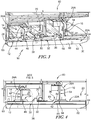
- a seal assembly 10 is adapted to close a gap 18 formed between first and second adjacent components 20, 30 in a gas turbine engine assembly 60 as shown in Figs. 1-6 .
- the gas turbine engine assembly 60 separates a high pressure zone HP from a low pressure zone LP within a gas turbine engine (not shown) as suggested in Figs. 1 and 2 .
- the seal assembly 10 is arranged in the gap 18 formed by the adjacent components 20, 30 to block gases from passing through the gap 18 between the high pressure zone HP and the low pressure zone LP during use of the gas turbine engine assembly 60.
- the components 20, 30 are positioned adjacent one another about a central axis of the gas turbine engine assembly 60.
- Each of the components 20, 30 are substantially similar and each includes a panel 22A, 22B, a forward hanger 24A, 24B, and an aft hanger 26A, 26B as shown in Figs. 1 and 2 .
- the seal assembly 10 includes a rod seal 12, a forward strip seal 14, and an aft strip seal 16.
- the rod seal 12 is arranged in a channel 28 formed by the panel 22A and the panel 22B to block gases from passing between the panels 22A, 22B.
- the forward strip seal 14 extends into the forward hanger 24A and the forward hanger 24B to block gases from passing therebetween.
- the aft strip seal 16 extends into the aft hanger 26A and the aft hanger 26B to block gases from passing therebetween.
- the components 20, 30 may heat and cool and grow relative to one another.
- the seals 12, 14, 16 are free to move relative to the components 20, 30 to allow for the relative movement and thermal growth of the components 20, 30.
- the forward strip seal 14 and the aft strip seal 16 are arranged to be interlocked with the rod seal 12 for radial movement therewith to block gases from passing between the rod seal 12 and the forward strip seal 14 and to block gases from passing between the rod seal 12 and the aft strip seal 16 as suggested in Fig. 6 .
- any gaps between the strip seals 14, 16 and the rod seal 12 are minimized or eliminated.
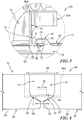
- the rod seal 12 includes a body 32 that extends axially relative to the center axis, a forward hook arm 34, and an aft hook arm 36 that is axially spaced apart from the forward hook arm 34 as shown in Figs. 3-5 .
- the body 32 is adapted to be located in the channel 28 to block gases from passing through the channel 28.
- a portion of the forward strip seal 14 is arranged to interlock with the forward hook arm 34.
- a portion of the aft strip seal 16 is arranged to interlock with the aft hook arm 36 included in the rod seal 12.
- the rod seal 12 further includes a locator flange 38 that extends radially outward away from the body 32 as shown in Figs. 3 and 4 .
- the locator flange 38 is adapted to engage structure surrounding the gas turbine engine assembly 60 such as, for example, the ground component 70 as shown in Fig. 3 , to axially locate the seal assembly 10.
- the illustrative locator flange 38 includes a radially extending planer surface 50 adapted to abut the ground component 70 to block axial movement of the seal assembly 10 relative to the ground component 70.
- Each of the components 20, 30 are substantially similar and each includes the panel 22A, 22B, the forward hanger 24A, 24B, and the aft hanger 26A, 26B respectively as shown in Figs. 1 and 2 .
- Each panel 22A, 22B of the components 20, 30 is illustratively formed to include a high pressure surface 61 and a low pressure surface 62 as shown in Fig. 2 .
- the high pressure surface 61 faces the high pressure zone HP and the low pressure surface 62 is opposite the high pressure surface 61 and faces the low pressure zone LP.
- Each panel 22A, 22B is also formed to include a forward surface 63, an aft surface 64, a left side surface 65, and a right side surface 66 as shown in Figs. 1 and 2 .
- each panel 22A, 22B is formed to include a left chamfer surface 67 and a right chamfer surface 68 as shown in Fig. 1 .
- the left chamfer surface 67 extends at an angle generally from the high pressure surface 61 to the left side surface 65 of the panel 22A, 22B.
- the right chamfer surface 68 extends at an angle generally from the high pressure surface 61 to the right side surface 66 of the panel 22A, 22B.
- the left chamfer surface 67 and the right chamfer surface 68 may be generally flat or barreled (curved).
- the left chamfer surface 67 and the right chamfer surface 68 extend along the corresponding left side surface 65 and the right side surface 66 from the forward surface 63 to the aft surface 64 as shown in Fig. 1 . Accordingly, the channel 28 extends from the forward surface 63 to the aft surface 64 of the panels 22A, 22B included in the first component 20 and the second component 30.
- the channel 28 is illustratively shaped with straight sides forming a generally triangular space for the rod seal 12 as shown in Fig. 6 . In other embodiments, the channel 28 may have curved or otherwise shaped sides that provide a space for the rod seal 12.
- the forward hanger 24A and the aft hanger 26A are integral with the panel 22A of the first component 20 and are adapted for coupling the panel 22A of the first component 20 with structure surrounding the gas turbine engine assembly 60 as suggested in Figs. 1 and 2 .
- the forward hanger 24A and the aft hanger 26A are generally L-shape and adapted to hang from brackets in a support structure.
- the forward hanger 24A and the aft hanger 26A may be dovetail shaped, may have pin-receiving holes, or have any other suitable shape for coupling the gas turbine engine assembly 60 with other structures.
- the forward hanger 24B and the aft hanger 26B of the second component 30 are substantially similar to the hangers 24A, 26A and are not discussed in detail.
- the forward hangers 24A, 24B and the aft hangers 26A, 26B are sometimes referred to as attachment features.
- Each of the forward hangers 24A, 24B is formed to include a slot 94A, 94B sized to receive the forward strip seal 14 as shown in Figs. 1 and 2 .
- the slots 94A, 94B of adjacent components 20, 30 cooperate to receive the strip seal 14.
- Each of the aft hangers 26A, 26B is formed to include a slot 96A, 96B sized to receive the aft strip seal 16.
- the gas turbine engine assembly 60 includes the ground component 70 as shown in Figs. 3 and 4 .
- the ground component 70 is arranged between the forward hangers 24A, 24B and the aft hangers 26A, 26B.
- the gas turbine engine assembly 60 may further include seals located between the ground component 70 and the components 20, 30 as shown in Fig. 3 .
- the seal assembly 10 is arranged in the channel 28 formed between the first component 20 and the second component 30 as shown in Figs. 1-3 .
- the seal assembly 10 illustratively includes the rod seal 12, the forward strip seal 14, and the aft strip seal 16.
- the forward strip seal 14 and the aft strip seal 16 are interlocked with the rod seal 12 for radial movement therewith.
- the rod seal 12 is arranged in the channel 28 formed by the left chamfer surface 67 and the right chamfer surface 68 to block gases from passing between the panels 22A, 22B as suggested in Figs. 2-4 and 6 .
- the rod seal 12 illustratively comprises ceramic matrix composite materials. In other embodiments, the rod seal 12 comprises ceramic monolithic materials, metallic materials, or other suitable materials.
- the rod seal 12 has a width 76 measured in the circumferential direction as shown in Fig. 6 .
- the rod seal 12 includes the body 32 that extends axially relative to the center axis, the forward hook arm 34, and the aft hook arm 36 axially spaced apart from the forward hook arm 34 as shown in Figs. 1-3 .
- the body 32, the forward hook arm 34, and the aft hook arm 36 are integrally formed to provide a monolithic rod seal 12.
- the body 32 is adapted to be located in the channel 28 to block gases from passing through the channel 28 as shown in Figs. 3, 4 , and 6 .
- the body 32 is illustratively sized to extend from the forward surfaces 63 to the aft surfaces 64 of the panels 22A, 22B as shown in Fig. 3 .
- the body 32 has a semicircular cross sectional profile.
- the body 32 may have a round cross sectional profile, a circular cross sectional profile, an elliptical cross sectional profile, or a polygonal cross sectional profile.
- the forward hook arm 34 extends away from the body 32 to form a forward slot 40 between the body 32 and the forward hook arm 34 as shown in Fig. 5 .
- the forward hook arm 34 extends radially outward away from the body 32 and axially forward to define the forward slot 40.
- a leg 46 of the forward strip seal 14 is arranged to extend into the forward slot 40 to interlock the forward strip seal 14 with the rod seal 12 as shown in Figs. 3-5 .
- the forward hook arm 34 includes a radially outward-facing surface 78, a radially inward-facing surface 79, and an end surface 80 that extends between and interconnects the radially outward-facing surface 78 and the radially inward-facing surface 79 as shown in Fig. 5 .
- the radially outward-facing surface 78, radially inward-facing surface 79, and the end surface 80 define a portion of the forward slot 40.
- the radially outward-facing surface 78 and the radially inward-facing surface 79 are radially spaced apart from one another such that the leg 46 of the forward strip seal 14 contacts only one of the radially outward-facing surface 78 and the radially inward-facing surface 79 at a time.
- the forward slot 40 has an axial length that is larger than an axial length of the leg 46 such that the forward hook arm 34 blocks the leg 46 from contacting the end surface 80.
- the aft hook arm 36 is axially spaced apart from the forward hook arm 34 as shown in Figs. 3 and 4 .
- the aft hook arm 36 extends away from the body 32 to form an aft slot 42 between the body 32 and the aft hook arm 36.
- the aft hook arm 36 extends radially outward away from the body 32 and axially aft to define the aft slot 42.
- a leg 56 of the aft strip seal 16 is arranged to extend into the aft slot 42 to interlock the aft strip seal 16 with the rod seal 12 as shown in Fig. 3 .
- the aft hook arm 36 includes a radially outward-facing surface 81, a radially inward-facing surface 82, and an end surface 83 that extends between and interconnects the radially outward-facing surface 81 and the radially inward-facing surface 82.
- the radially outward-facing surface 81, radially inward-facing surface 82, and the end surface 83 define a portion of the aft slot 42.
- the radially outward-facing surface 81 and the radially inward-facing surface 82 are radially spaced apart from one another such that the leg 56 may contact only one of the radially outward-facing surface 81 and the radially inward-facing surface 82 at a time.
- the aft slot 42 has an axial length that is larger than an axial length of the leg 56 such that the aft hook arm 36 blocks the leg 56 from contacting the end surface 83.
- the rod seal 12 further includes a locator flange 38 that extends radially outward away from the body 32 as shown in Fig. 3 .
- the locator flange 38 is adapted to engage structure surrounding the gas turbine engine assembly 60 such as, for example, the ground component 70, to axially locate the seal assembly 10.
- the locator flange 38 includes a radially extending planer surface 50 adapted to abut the ground component 70 to block axial movement of the rod seal 12 relative to the ground component 70.
- the forward strip seal 14 includes a radially extending seal strip 44 and a leg 46 as shown in Fig. 3 .
- the seal strip 44 extends circumferentially across the gap 18 into the slots 94A, 94B formed in the forward hangers 24A, 24B.
- the leg 46 extends axially away from the seal strip 44 and is arranged to extend into the forward slot 40 to interlock the forward strip seal 14 with the rod seal 12.
- the leg 46 of the forward strip seal 14 is spaced apart from one of the body 32 and the forward hook arm 34 of the rod seal 12 to allow for thermal growth between the components during use of the gas turbine engine assembly 60.
- the seal strip 44 of the forward strip seal 14 has a width 48 and the leg 46 has a width 49 as shown in Fig. 6 .
- the width 76 of the rod seal 12 is greater than the width 49 of the leg.
- the width 48 of the seal strip 44 is greater than the width 76 of the rod and the width 49 of the leg.
- the leg 46 is free to move circumferentially relative to the rod seal 12 in the forward slot 40.
- the seal strip 44 is free to move circumferentially relative to the components 20, 30 in the slots 94A, 94B.
- the rod seal 12, forward strip seal 14, and the aft strip seal 16 are free to move radially inward and outward relative to the components 20, 30.
- the leg 46 and the seal strip 44 define an apex as shown in Fig. 5 .
- the seal strip 44 and the leg 46 extend linearly away from the apex 98.
- the leg 46 and the seal strip 44 cooperate to define an angle alpha therebetween as shown in Fig. 5 .
- the angle alpha is about 90 degrees.
- the angle alpha is greater than 90 degrees.
- the angle alpha is less than 90 degrees.
- the leg 46 and the seal strip 44 cooperate to form a sharp point (not a radius) to minimize or eliminate bypass flow around the strip seal 14.
- the seal strip 44 and the leg 46 are separate components and the leg 46 is coupled to the seal strip 44 as suggested in Fig. 5 .
- the seal strip 44 is formed from a single sheet of material having a uniform thickness to provide a flat plate as shown in Figs. 3-5 .
- the leg 46 is L-shaped and coupled to the seal strip 44.
- the leg 46 is welded or brazed to the seal strip 44.
- the strip seal 14 is formed through a metal injection molding process. As a result, the seal strip 44 and the leg 46 made integral as one piece through the metal injection molding process.
- the aft strip seal 16 includes a radially extending seal strip 54 and a leg 56 as shown in Fig. 3 .
- the seal strip 54 extends circumferentially across the gap 18 into the slots 96A, 96B formed in the aft hangers 26A, 26B.
- the leg 56 extends axially away from the seal strip 54 and is arranged to extend into the aft slot 42 to interlock the aft strip seal 16 with the rod seal 12.
- the leg 56 is spaced apart from one of the body 32 and the aft hook arm 36 of the rod seal 12 to allow for thermal growth between the components during use of the gas turbine engine assembly 60.
- the aft strip seal 16 is substantially similar to the forward strip seal 14 and is not discussed in detail.
- FIG. 7 and 8 Another embodiment of a seal assembly 210 for use in a gas turbine engine assembly 260 is shown in Figs. 7 and 8 .
- the seal assembly 210 is substantially similar to the seal assembly 10 shown in Figs. 1-6 and described herein. Accordingly, similar reference numbers in the 200 series indicate features that are common between the seal assembly 10 and the seal assembly 210.
- the description of the seal assembly 10 is incorporated by reference to apply to the seal assembly 210, except in instances when it conflicts with the specific description and the drawings of the seal assembly 210.
- the seal assembly 210 includes the rod seal 212, a forward strip seal 214, and an aft strip seal 216 as shown in Fig. 7 .
- the rod seal 212 includes an aft hook arm 236 having a semi-circular cross section as shown in Figs. 7 and 8 .
- the aft strip seal 216 includes a seal strip 254 and a leg 256.
- the seal strip 254 and the leg 256 are formed from a monolithic component as shown in Figs. 7 and 8 .
- a single sheet of material may be contoured and machined to provide the seal strip 254 and the leg 256.
- the illustrative seal strip 254 is contoured to fit in a contoured slot 96A of component 220.
- the leg 256 extends axially away from an inner end of the seal strip 254.
- the single sheet of material of the aft strip seal 216 has been machined to reduce a width 249 of the leg such that the width 249 of the leg 256 is less than a width 248 of the seal strip 254.
- the forward seal strip 214 is substantially similar to the aft strip seal 216 and is not discussed in detail.
- an outer annulus of a hot gas flow path is defined by the segment components such as, for example, shroud or blade track components.
- the segment components may shield other components such as, for example, carriers and casings, outside of the segment components from high flow path temperatures.
- the segment components may be bathed in cooling air at a lower temperature and higher pressure than the flow path gases for their survivability.
- the outer annulus may be made from a number of segments around the annulus. Throughout the engine cycle, the segments may move together and apart.
- the inter-platform (circumferential) gaps between segments may open and close through engine operation. These gaps are typically closed up to seal the cooling air system from the flow path, high temperature air.
- this seal includes a thin, planer, sheet metal, strip seal that fits into opposing grooves in adjacent metallic segments.
- seals and simple grooves may provide challenges.
- a groove feature created in a ceramic matrix composite member (flow path runner) that directly separates the hot and cold air may create high stresses from the combination of a high thermal gradient through the part thicknesses and the geometric stress riser from the then groove feature itself and associated fillets.
- the thermal stress issue may be exaggerated in the ceramic matrix composite due to a lower thermal conductivity of the material in comparison to a metal segment.
- the thin strip seal could be replaced by a rod seal along the flow path.
- a sheet metal strip seal may be used in the vertical hangers of the segments to seal the segment cavity axially on the forward and aft sides.
- the thermal gradient through the hangers may be smaller when compared to the thermal gradient through the flow path runner allowing this seal configuration in the hangers of the segment.
- the vertical strip seals in the hangers may remain static in position due to the pressure load acting across them.
- the rod seal however may not stay static with respect to the vertical strip seals.
- the rod seal position could move radially with respect to the strip seals since the rod seal is seated on a chamfered surface of the segment.
- a leakage area may exist between segments, rod seal, and strip seal. This area may grow as the inter-platform gap grows.
- the radial location of the rod seal and the strip seals are tied together.
- the illustrative rod seal has opposing hook features created to radially tie the location of the strip seal to the rod seal. This may eliminate/minimize the gap between the rod seal and the strip seal.
- Each of the strip seals illustratively include a horizontal leg that fits in the groove formed by the hooks in the rod seal as a locating function.
- the width of the groove is larger than the thickness of the strip seal.
- the strip seal may be allowed to slide horizontally with respect to the rod seal which may be helpful because the horizontal distance between the forward seal and aft strip seal may be dependent on the growth of the ceramic matrix composite segment (low alpha).
- the horizontal distance between the rod seal hooks may grow differently since it may be made from a metal material such as, for example, a high temperature nickel or cobalt alloy (higher alpha). Maintaining strip seal freedom to move axially and seal against the sealing surface in the segment hangers may reduce leakages.
- Illustrative embodiments show a strip seal with a vertical leg and a horizontal gap.
- the external corner between these legs is a sharp corner.
- the sharp corner may eliminate or reduce an additional bypass area.
- This sharp corner may be made by joining two components with brazing, welding, etc, could be machined out of stock material, could be produced with metal injection molding, or could be produced with additive material technology (3D metal "printing").
- the strip seals are made from a single piece of bent sheet metal.
- the components 20, 30 are blade track segments 20, 30 made from ceramic matrix materials that may be used with other blade track segments to provide a ring that extends around the center axis of the gas turbine engine assembly 60.
- the ring is arranged around rotating turbine wheels used in the gas turbine engine to form a gas path for directing gases through the gas turbine engine.
- the components 20, 30 are made from materials other than ceramic matrix composite materials.
- the components 20, 30 are adapted for use as combustor tiles included in the combustor of a gas turbine engine or as heat shields included in other sections of a gas turbine engine.
Landscapes
- Engineering & Computer Science (AREA)
- General Engineering & Computer Science (AREA)
- Mechanical Engineering (AREA)
- Physics & Mathematics (AREA)
- Geometry (AREA)
- Gasket Seals (AREA)
- Turbine Rotor Nozzle Sealing (AREA)
Applications Claiming Priority (1)
| Application Number | Priority Date | Filing Date | Title |
|---|---|---|---|
| US15/403,834 US10443420B2 (en) | 2017-01-11 | 2017-01-11 | Seal assembly for gas turbine engine components |
Publications (2)
| Publication Number | Publication Date |
|---|---|
| EP3348792A1 true EP3348792A1 (fr) | 2018-07-18 |
| EP3348792B1 EP3348792B1 (fr) | 2019-07-24 |
Family
ID=60654820
Family Applications (1)
| Application Number | Title | Priority Date | Filing Date |
|---|---|---|---|
| EP17206340.6A Active EP3348792B1 (fr) | 2017-01-11 | 2017-12-11 | Ensemble d'étanchéité pour composants de moteur de turbine à gaz |
Country Status (3)
| Country | Link |
|---|---|
| US (1) | US10443420B2 (fr) |
| EP (1) | EP3348792B1 (fr) |
| CA (1) | CA2987443A1 (fr) |
Families Citing this family (27)
| Publication number | Priority date | Publication date | Assignee | Title |
|---|---|---|---|---|
| US9759079B2 (en) | 2015-05-28 | 2017-09-12 | Rolls-Royce Corporation | Split line flow path seals |
| GB201603554D0 (en) * | 2016-03-01 | 2016-04-13 | Rolls Royce Plc | An intercomponent seal for a gas turbine engine |
| US10718226B2 (en) | 2017-11-21 | 2020-07-21 | Rolls-Royce Corporation | Ceramic matrix composite component assembly and seal |
| US10907491B2 (en) * | 2017-11-30 | 2021-02-02 | General Electric Company | Sealing system for a rotary machine and method of assembling same |
| US10961861B2 (en) * | 2018-08-06 | 2021-03-30 | Raytheon Technologies Corporation | Structural support for blade outer air seal assembly |
| US10794206B2 (en) | 2018-09-05 | 2020-10-06 | Raytheon Technologies Corporation | CMC BOAS intersegment seal |
| US10808553B2 (en) | 2018-11-13 | 2020-10-20 | Rolls-Royce Plc | Inter-component seals for ceramic matrix composite turbine vane assemblies |
| US11319827B2 (en) * | 2019-04-01 | 2022-05-03 | Raytheon Technologies Corporation | Intersegment seal for blade outer air seal |
| US11326463B2 (en) * | 2019-06-19 | 2022-05-10 | Raytheon Technologies Corporation | BOAS thermal baffle |
| US11066947B2 (en) * | 2019-12-18 | 2021-07-20 | Rolls-Royce Corporation | Turbine shroud assembly with sealed pin mounting arrangement |
| US11629607B2 (en) * | 2021-05-25 | 2023-04-18 | Rolls-Royce Corporation | Turbine shroud assembly with radially and axially biased ceramic matrix composite shroud segments |
| US12241376B1 (en) | 2023-12-04 | 2025-03-04 | Rolls-Royce Corporation | Locating plate for use with turbine shroud assemblies |
| US12152499B1 (en) | 2023-12-04 | 2024-11-26 | Rolls-Royce Corporation | Turbine shroud segments with strip seal assemblies having dampened ends |
| US12158072B1 (en) | 2023-12-04 | 2024-12-03 | Rolls-Royce Corporation | Turbine shroud segments with damping strip seals |
| US12421862B2 (en) | 2023-12-04 | 2025-09-23 | Rolls-Royce Corporation | Turbine shroud assembly with angled cooling holes |
| US12286906B1 (en) | 2023-12-04 | 2025-04-29 | Rolls-Royce Corporation | Locating plate for use with turbine shroud assemblies |
| US12286885B1 (en) | 2023-12-04 | 2025-04-29 | Rolls-Royce Corporation | Turbine assembly with confronting vane and turbine shroud segment |
| US12188365B1 (en) | 2023-12-04 | 2025-01-07 | Rolls-Royce Corporation | Method and apparatus for ceramic matrix composite turbine shroud assembly |
| US12421870B1 (en) | 2024-04-30 | 2025-09-23 | Rolls-Royce Corporation | Pin mounted ceramic matrix composite heat shields with impingement cooling |
| US12305525B1 (en) * | 2024-05-30 | 2025-05-20 | Rolls-Royce Corporation | Turbine shroud assemblies with rod seal and strip seals |
| US12215593B1 (en) | 2024-05-30 | 2025-02-04 | Rolls-Royce Corporation | Turbine shroud assembly with inter-segment damping |
| US12416241B1 (en) * | 2024-05-30 | 2025-09-16 | Rolls-Royce Corporation | Turbine shroud assemblies with strip seals |
| US12258880B1 (en) * | 2024-05-30 | 2025-03-25 | Rolls-Royce Corporation | Turbine shroud assemblies with inter-segment strip seal |
| US12352176B1 (en) | 2024-05-31 | 2025-07-08 | Rolls-Royce Corporation | Turbine shroud assemblies with channels for buffer cavity seal thermal management |
| US12410725B1 (en) | 2024-05-31 | 2025-09-09 | Rolls-Royce Corporation | Turbine shroud assemblies with air activated pistons for biasing buffer cavity seals |
| US12577881B2 (en) | 2024-05-31 | 2026-03-17 | Rolls-Royce Corporation | Turbine shroud assemblies with anti-migration seals |
| US12228044B1 (en) | 2024-06-26 | 2025-02-18 | Rolls-Royce Corporation | Turbine shroud system with ceramic matrix composite segments and dual inter-segment seals |
Citations (5)
| Publication number | Priority date | Publication date | Assignee | Title |
|---|---|---|---|---|
| US5188507A (en) * | 1991-11-27 | 1993-02-23 | General Electric Company | Low-pressure turbine shroud |
| US5988975A (en) * | 1996-05-20 | 1999-11-23 | Pratt & Whitney Canada Inc. | Gas turbine engine shroud seals |
| US20100247298A1 (en) * | 2009-03-27 | 2010-09-30 | Honda Motor Co., Ltd. | Turbine shroud |
| US20160017721A1 (en) * | 2014-07-21 | 2016-01-21 | Rolls-Royce Corporation | Composite turbine components adapted for use with strip seals |
| EP3106622A1 (fr) * | 2015-05-28 | 2016-12-21 | Rolls-Royce Corporation | Joints de trajet d'écoulement à ligne fendue |
Family Cites Families (40)
| Publication number | Priority date | Publication date | Assignee | Title |
|---|---|---|---|---|
| US1423466A (en) | 1920-10-02 | 1922-07-18 | Westinghouse Electric & Mfg Co | Interlocking blade shroud |
| US3375016A (en) | 1964-03-09 | 1968-03-26 | Navy Usa | Two-stage seal arrangement |
| US3661197A (en) | 1970-02-09 | 1972-05-09 | Edwin F Peterson | Corebox and seal |
| JPS5632441B2 (fr) | 1973-11-30 | 1981-07-28 | ||
| JPS58176402A (ja) | 1982-04-10 | 1983-10-15 | Toshiba Corp | タ−ビン動翼の制振装置 |
| US4524980A (en) * | 1983-12-05 | 1985-06-25 | United Technologies Corporation | Intersecting feather seals for interlocking gas turbine vanes |
| US4635896A (en) | 1986-04-04 | 1987-01-13 | Baker Edwin L | Method of sealing a joint between an ingot mold and a stool and resulting assembly |
| US5188506A (en) | 1991-08-28 | 1993-02-23 | General Electric Company | Apparatus and method for preventing leakage of cooling air in a shroud assembly of a gas turbine engine |
| US5709530A (en) * | 1996-09-04 | 1998-01-20 | United Technologies Corporation | Gas turbine vane seal |
| US5868398A (en) * | 1997-05-20 | 1999-02-09 | United Technologies Corporation | Gas turbine stator vane seal |
| JP2000204901A (ja) | 1999-01-08 | 2000-07-25 | Mitsubishi Heavy Ind Ltd | 軸流回転機械における動翼の制振構造 |
| EP1191285A1 (fr) | 2000-09-22 | 2002-03-27 | Siemens Aktiengesellschaft | Bouclier thérmique , chambre de combustion avec garnissage interne et turbine à gaz |
| US6464456B2 (en) | 2001-03-07 | 2002-10-15 | General Electric Company | Turbine vane assembly including a low ductility vane |
| US7080513B2 (en) | 2001-08-04 | 2006-07-25 | Siemens Aktiengesellschaft | Seal element for sealing a gap and combustion turbine having a seal element |
| US6893214B2 (en) | 2002-12-20 | 2005-05-17 | General Electric Company | Shroud segment and assembly with surface recessed seal bridging adjacent members |
| US6808363B2 (en) | 2002-12-20 | 2004-10-26 | General Electric Company | Shroud segment and assembly with circumferential seal at a planar segment surface |
| JP2004286987A (ja) | 2003-03-20 | 2004-10-14 | Olympus Corp | 防水構造 |
| JP4495481B2 (ja) | 2004-02-18 | 2010-07-07 | イーグル・エンジニアリング・エアロスペース株式会社 | シール装置 |
| GB2417528B (en) | 2004-08-23 | 2008-08-06 | Alstom Technology Ltd | Improved rope seal for gas turbine engines |
| US7374395B2 (en) | 2005-07-19 | 2008-05-20 | Pratt & Whitney Canada Corp. | Turbine shroud segment feather seal located in radial shroud legs |
| JP4962687B2 (ja) | 2005-08-30 | 2012-06-27 | Nok株式会社 | 密封構造 |
| GB2434184B (en) | 2006-01-12 | 2007-12-12 | Rolls Royce Plc | A sealing arrangement |
| GB0610271D0 (en) | 2006-05-24 | 2006-07-05 | Rolls Royce Plc | A gas turbine engine casing |
| US7520721B2 (en) | 2006-09-19 | 2009-04-21 | General Electric Company | System and method for aligning and sealing a turbine shell assembly |
| US7870738B2 (en) | 2006-09-29 | 2011-01-18 | Siemens Energy, Inc. | Gas turbine: seal between adjacent can annular combustors |
| US7771159B2 (en) | 2006-10-16 | 2010-08-10 | General Electric Company | High temperature seals and high temperature sealing systems |
| US8047773B2 (en) | 2007-08-23 | 2011-11-01 | General Electric Company | Gas turbine shroud support apparatus |
| JP4991663B2 (ja) | 2007-09-11 | 2012-08-01 | 株式会社日立製作所 | 蒸気タービン動翼組立体 |
| US8157511B2 (en) | 2008-09-30 | 2012-04-17 | Pratt & Whitney Canada Corp. | Turbine shroud gas path duct interface |
| US8047550B2 (en) | 2009-02-09 | 2011-11-01 | The Boeing Company | Tile gap seal assembly and method |
| DE102009022393B4 (de) | 2009-05-22 | 2011-09-22 | Federal-Mogul Sealing Systems Gmbh | Verfahren zur Herstellung metallischer Elemente, insbesondere Dichtelemente |
| US8303245B2 (en) | 2009-10-09 | 2012-11-06 | General Electric Company | Shroud assembly with discourager |
| US8684695B2 (en) * | 2011-01-04 | 2014-04-01 | General Electric Company | Damper coverplate and sealing arrangement for turbine bucket shank |
| US8727710B2 (en) * | 2011-01-24 | 2014-05-20 | United Technologies Corporation | Mateface cooling feather seal assembly |
| JP5776208B2 (ja) | 2011-02-16 | 2015-09-09 | マツダ株式会社 | 車両前部構造 |
| US8790067B2 (en) | 2011-04-27 | 2014-07-29 | United Technologies Corporation | Blade clearance control using high-CTE and low-CTE ring members |
| GB201117084D0 (en) * | 2011-10-05 | 2011-11-16 | Rolls Royce Plc | Strip seals |
| US9726043B2 (en) | 2011-12-15 | 2017-08-08 | General Electric Company | Mounting apparatus for low-ductility turbine shroud |
| US20130202433A1 (en) | 2012-02-07 | 2013-08-08 | General Electric Company | Seal assembly for turbine coolant passageways |
| US10281045B2 (en) | 2015-02-20 | 2019-05-07 | Rolls-Royce North American Technologies Inc. | Apparatus and methods for sealing components in gas turbine engines |
-
2017
- 2017-01-11 US US15/403,834 patent/US10443420B2/en active Active
- 2017-12-01 CA CA2987443A patent/CA2987443A1/fr not_active Abandoned
- 2017-12-11 EP EP17206340.6A patent/EP3348792B1/fr active Active
Patent Citations (5)
| Publication number | Priority date | Publication date | Assignee | Title |
|---|---|---|---|---|
| US5188507A (en) * | 1991-11-27 | 1993-02-23 | General Electric Company | Low-pressure turbine shroud |
| US5988975A (en) * | 1996-05-20 | 1999-11-23 | Pratt & Whitney Canada Inc. | Gas turbine engine shroud seals |
| US20100247298A1 (en) * | 2009-03-27 | 2010-09-30 | Honda Motor Co., Ltd. | Turbine shroud |
| US20160017721A1 (en) * | 2014-07-21 | 2016-01-21 | Rolls-Royce Corporation | Composite turbine components adapted for use with strip seals |
| EP3106622A1 (fr) * | 2015-05-28 | 2016-12-21 | Rolls-Royce Corporation | Joints de trajet d'écoulement à ligne fendue |
Also Published As
| Publication number | Publication date |
|---|---|
| CA2987443A1 (fr) | 2018-07-11 |
| US20180195401A1 (en) | 2018-07-12 |
| EP3348792B1 (fr) | 2019-07-24 |
| US10443420B2 (en) | 2019-10-15 |
Similar Documents
| Publication | Publication Date | Title |
|---|---|---|
| EP3348792B1 (fr) | Ensemble d'étanchéité pour composants de moteur de turbine à gaz | |
| EP3327254B1 (fr) | Ensemble d'étanchéité pour composants de moteur à turbine à gaz | |
| US10577977B2 (en) | Turbine shroud with biased retaining ring | |
| US4087199A (en) | Ceramic turbine shroud assembly | |
| US10704404B2 (en) | Seals for a gas turbine engine assembly | |
| EP3670844B1 (fr) | Ensemble de suspension de carenage | |
| EP3425169B1 (fr) | Ensemble d'enveloppe de turbine comportant des joints en plusieurs parties | |
| US9745854B2 (en) | Shroud assembly and seal for a gas turbine engine | |
| KR100776072B1 (ko) | 가스 터빈 | |
| US10329950B2 (en) | Nozzle guide vane with composite heat shield | |
| EP3155231B1 (fr) | Ensemble dispositif de suspension de carénage | |
| JP2007107524A (ja) | セラミックマトリックス複合物体内の熱応力を制御するアセンブリ | |
| EP3090138B1 (fr) | Écrans thermiques pour joints d'étanchéité à l'air | |
| US9945239B2 (en) | Vane carrier for a compressor or a turbine section of an axial turbo machine | |
| US3412977A (en) | Segmented annular sealing ring and method of its manufacture | |
| US20070031244A1 (en) | Thermally compliant turbine shroud assembly | |
| EP3047130B1 (fr) | Turbine à gaz comprenant joints d'étanchéité à nid d'abeilles cannelé | |
| US10436041B2 (en) | Shroud assembly for turbine systems |
Legal Events
| Date | Code | Title | Description |
|---|---|---|---|
| PUAI | Public reference made under article 153(3) epc to a published international application that has entered the european phase |
Free format text: ORIGINAL CODE: 0009012 |
|
| STAA | Information on the status of an ep patent application or granted ep patent |
Free format text: STATUS: THE APPLICATION HAS BEEN PUBLISHED |
|
| AK | Designated contracting states |
Kind code of ref document: A1 Designated state(s): AL AT BE BG CH CY CZ DE DK EE ES FI FR GB GR HR HU IE IS IT LI LT LU LV MC MK MT NL NO PL PT RO RS SE SI SK SM TR |
|
| AX | Request for extension of the european patent |
Extension state: BA ME |
|
| STAA | Information on the status of an ep patent application or granted ep patent |
Free format text: STATUS: REQUEST FOR EXAMINATION WAS MADE |
|
| 17P | Request for examination filed |
Effective date: 20190115 |
|
| RBV | Designated contracting states (corrected) |
Designated state(s): AL AT BE BG CH CY CZ DE DK EE ES FI FR GB GR HR HU IE IS IT LI LT LU LV MC MK MT NL NO PL PT RO RS SE SI SK SM TR |
|
| GRAP | Despatch of communication of intention to grant a patent |
Free format text: ORIGINAL CODE: EPIDOSNIGR1 |
|
| STAA | Information on the status of an ep patent application or granted ep patent |
Free format text: STATUS: GRANT OF PATENT IS INTENDED |
|
| RIC1 | Information provided on ipc code assigned before grant |
Ipc: F01D 25/24 20060101ALI20190228BHEP Ipc: F01D 11/00 20060101AFI20190228BHEP Ipc: F01D 9/04 20060101ALI20190228BHEP Ipc: F16J 15/06 20060101ALI20190228BHEP |
|
| INTG | Intention to grant announced |
Effective date: 20190401 |
|
| GRAS | Grant fee paid |
Free format text: ORIGINAL CODE: EPIDOSNIGR3 |
|
| GRAA | (expected) grant |
Free format text: ORIGINAL CODE: 0009210 |
|
| STAA | Information on the status of an ep patent application or granted ep patent |
Free format text: STATUS: THE PATENT HAS BEEN GRANTED |
|
| AK | Designated contracting states |
Kind code of ref document: B1 Designated state(s): AL AT BE BG CH CY CZ DE DK EE ES FI FR GB GR HR HU IE IS IT LI LT LU LV MC MK MT NL NO PL PT RO RS SE SI SK SM TR |
|
| REG | Reference to a national code |
Ref country code: GB Ref legal event code: FG4D |
|
| REG | Reference to a national code |
Ref country code: CH Ref legal event code: EP |
|
| REG | Reference to a national code |
Ref country code: DE Ref legal event code: R096 Ref document number: 602017005535 Country of ref document: DE |
|
| REG | Reference to a national code |
Ref country code: AT Ref legal event code: REF Ref document number: 1158436 Country of ref document: AT Kind code of ref document: T Effective date: 20190815 |
|
| REG | Reference to a national code |
Ref country code: IE Ref legal event code: FG4D |
|
| REG | Reference to a national code |
Ref country code: NL Ref legal event code: MP Effective date: 20190724 |
|
| REG | Reference to a national code |
Ref country code: LT Ref legal event code: MG4D |
|
| REG | Reference to a national code |
Ref country code: AT Ref legal event code: MK05 Ref document number: 1158436 Country of ref document: AT Kind code of ref document: T Effective date: 20190724 |
|
| PG25 | Lapsed in a contracting state [announced via postgrant information from national office to epo] |
Ref country code: SE Free format text: LAPSE BECAUSE OF FAILURE TO SUBMIT A TRANSLATION OF THE DESCRIPTION OR TO PAY THE FEE WITHIN THE PRESCRIBED TIME-LIMIT Effective date: 20190724 Ref country code: HR Free format text: LAPSE BECAUSE OF FAILURE TO SUBMIT A TRANSLATION OF THE DESCRIPTION OR TO PAY THE FEE WITHIN THE PRESCRIBED TIME-LIMIT Effective date: 20190724 Ref country code: FI Free format text: LAPSE BECAUSE OF FAILURE TO SUBMIT A TRANSLATION OF THE DESCRIPTION OR TO PAY THE FEE WITHIN THE PRESCRIBED TIME-LIMIT Effective date: 20190724 Ref country code: LT Free format text: LAPSE BECAUSE OF FAILURE TO SUBMIT A TRANSLATION OF THE DESCRIPTION OR TO PAY THE FEE WITHIN THE PRESCRIBED TIME-LIMIT Effective date: 20190724 Ref country code: PT Free format text: LAPSE BECAUSE OF FAILURE TO SUBMIT A TRANSLATION OF THE DESCRIPTION OR TO PAY THE FEE WITHIN THE PRESCRIBED TIME-LIMIT Effective date: 20191125 Ref country code: NL Free format text: LAPSE BECAUSE OF FAILURE TO SUBMIT A TRANSLATION OF THE DESCRIPTION OR TO PAY THE FEE WITHIN THE PRESCRIBED TIME-LIMIT Effective date: 20190724 Ref country code: BG Free format text: LAPSE BECAUSE OF FAILURE TO SUBMIT A TRANSLATION OF THE DESCRIPTION OR TO PAY THE FEE WITHIN THE PRESCRIBED TIME-LIMIT Effective date: 20191024 Ref country code: NO Free format text: LAPSE BECAUSE OF FAILURE TO SUBMIT A TRANSLATION OF THE DESCRIPTION OR TO PAY THE FEE WITHIN THE PRESCRIBED TIME-LIMIT Effective date: 20191024 Ref country code: AT Free format text: LAPSE BECAUSE OF FAILURE TO SUBMIT A TRANSLATION OF THE DESCRIPTION OR TO PAY THE FEE WITHIN THE PRESCRIBED TIME-LIMIT Effective date: 20190724 |
|
| PG25 | Lapsed in a contracting state [announced via postgrant information from national office to epo] |
Ref country code: AL Free format text: LAPSE BECAUSE OF FAILURE TO SUBMIT A TRANSLATION OF THE DESCRIPTION OR TO PAY THE FEE WITHIN THE PRESCRIBED TIME-LIMIT Effective date: 20190724 Ref country code: ES Free format text: LAPSE BECAUSE OF FAILURE TO SUBMIT A TRANSLATION OF THE DESCRIPTION OR TO PAY THE FEE WITHIN THE PRESCRIBED TIME-LIMIT Effective date: 20190724 Ref country code: IS Free format text: LAPSE BECAUSE OF FAILURE TO SUBMIT A TRANSLATION OF THE DESCRIPTION OR TO PAY THE FEE WITHIN THE PRESCRIBED TIME-LIMIT Effective date: 20191124 Ref country code: LV Free format text: LAPSE BECAUSE OF FAILURE TO SUBMIT A TRANSLATION OF THE DESCRIPTION OR TO PAY THE FEE WITHIN THE PRESCRIBED TIME-LIMIT Effective date: 20190724 Ref country code: RS Free format text: LAPSE BECAUSE OF FAILURE TO SUBMIT A TRANSLATION OF THE DESCRIPTION OR TO PAY THE FEE WITHIN THE PRESCRIBED TIME-LIMIT Effective date: 20190724 Ref country code: GR Free format text: LAPSE BECAUSE OF FAILURE TO SUBMIT A TRANSLATION OF THE DESCRIPTION OR TO PAY THE FEE WITHIN THE PRESCRIBED TIME-LIMIT Effective date: 20191025 |
|
| PG25 | Lapsed in a contracting state [announced via postgrant information from national office to epo] |
Ref country code: TR Free format text: LAPSE BECAUSE OF FAILURE TO SUBMIT A TRANSLATION OF THE DESCRIPTION OR TO PAY THE FEE WITHIN THE PRESCRIBED TIME-LIMIT Effective date: 20190724 |
|
| PG25 | Lapsed in a contracting state [announced via postgrant information from national office to epo] |
Ref country code: IT Free format text: LAPSE BECAUSE OF FAILURE TO SUBMIT A TRANSLATION OF THE DESCRIPTION OR TO PAY THE FEE WITHIN THE PRESCRIBED TIME-LIMIT Effective date: 20190724 Ref country code: RO Free format text: LAPSE BECAUSE OF FAILURE TO SUBMIT A TRANSLATION OF THE DESCRIPTION OR TO PAY THE FEE WITHIN THE PRESCRIBED TIME-LIMIT Effective date: 20190724 Ref country code: DK Free format text: LAPSE BECAUSE OF FAILURE TO SUBMIT A TRANSLATION OF THE DESCRIPTION OR TO PAY THE FEE WITHIN THE PRESCRIBED TIME-LIMIT Effective date: 20190724 Ref country code: EE Free format text: LAPSE BECAUSE OF FAILURE TO SUBMIT A TRANSLATION OF THE DESCRIPTION OR TO PAY THE FEE WITHIN THE PRESCRIBED TIME-LIMIT Effective date: 20190724 Ref country code: PL Free format text: LAPSE BECAUSE OF FAILURE TO SUBMIT A TRANSLATION OF THE DESCRIPTION OR TO PAY THE FEE WITHIN THE PRESCRIBED TIME-LIMIT Effective date: 20190724 |
|
| PG25 | Lapsed in a contracting state [announced via postgrant information from national office to epo] |
Ref country code: IS Free format text: LAPSE BECAUSE OF FAILURE TO SUBMIT A TRANSLATION OF THE DESCRIPTION OR TO PAY THE FEE WITHIN THE PRESCRIBED TIME-LIMIT Effective date: 20200224 Ref country code: SM Free format text: LAPSE BECAUSE OF FAILURE TO SUBMIT A TRANSLATION OF THE DESCRIPTION OR TO PAY THE FEE WITHIN THE PRESCRIBED TIME-LIMIT Effective date: 20190724 Ref country code: SK Free format text: LAPSE BECAUSE OF FAILURE TO SUBMIT A TRANSLATION OF THE DESCRIPTION OR TO PAY THE FEE WITHIN THE PRESCRIBED TIME-LIMIT Effective date: 20190724 Ref country code: CZ Free format text: LAPSE BECAUSE OF FAILURE TO SUBMIT A TRANSLATION OF THE DESCRIPTION OR TO PAY THE FEE WITHIN THE PRESCRIBED TIME-LIMIT Effective date: 20190724 |
|
| REG | Reference to a national code |
Ref country code: DE Ref legal event code: R097 Ref document number: 602017005535 Country of ref document: DE |
|
| PLBE | No opposition filed within time limit |
Free format text: ORIGINAL CODE: 0009261 |
|
| STAA | Information on the status of an ep patent application or granted ep patent |
Free format text: STATUS: NO OPPOSITION FILED WITHIN TIME LIMIT |
|
| PG2D | Information on lapse in contracting state deleted |
Ref country code: IS |
|
| 26N | No opposition filed |
Effective date: 20200603 |
|
| REG | Reference to a national code |
Ref country code: BE Ref legal event code: MM Effective date: 20191231 |
|
| PG25 | Lapsed in a contracting state [announced via postgrant information from national office to epo] |
Ref country code: MC Free format text: LAPSE BECAUSE OF FAILURE TO SUBMIT A TRANSLATION OF THE DESCRIPTION OR TO PAY THE FEE WITHIN THE PRESCRIBED TIME-LIMIT Effective date: 20190724 Ref country code: SI Free format text: LAPSE BECAUSE OF FAILURE TO SUBMIT A TRANSLATION OF THE DESCRIPTION OR TO PAY THE FEE WITHIN THE PRESCRIBED TIME-LIMIT Effective date: 20190724 |
|
| PG25 | Lapsed in a contracting state [announced via postgrant information from national office to epo] |
Ref country code: IE Free format text: LAPSE BECAUSE OF NON-PAYMENT OF DUE FEES Effective date: 20191211 Ref country code: LU Free format text: LAPSE BECAUSE OF NON-PAYMENT OF DUE FEES Effective date: 20191211 |
|
| PG25 | Lapsed in a contracting state [announced via postgrant information from national office to epo] |
Ref country code: BE Free format text: LAPSE BECAUSE OF NON-PAYMENT OF DUE FEES Effective date: 20191231 |
|
| PG25 | Lapsed in a contracting state [announced via postgrant information from national office to epo] |
Ref country code: CY Free format text: LAPSE BECAUSE OF FAILURE TO SUBMIT A TRANSLATION OF THE DESCRIPTION OR TO PAY THE FEE WITHIN THE PRESCRIBED TIME-LIMIT Effective date: 20190724 |
|
| PG25 | Lapsed in a contracting state [announced via postgrant information from national office to epo] |
Ref country code: MT Free format text: LAPSE BECAUSE OF FAILURE TO SUBMIT A TRANSLATION OF THE DESCRIPTION OR TO PAY THE FEE WITHIN THE PRESCRIBED TIME-LIMIT Effective date: 20190724 Ref country code: HU Free format text: LAPSE BECAUSE OF FAILURE TO SUBMIT A TRANSLATION OF THE DESCRIPTION OR TO PAY THE FEE WITHIN THE PRESCRIBED TIME-LIMIT; INVALID AB INITIO Effective date: 20171211 |
|
| REG | Reference to a national code |
Ref country code: CH Ref legal event code: PL |
|
| PG25 | Lapsed in a contracting state [announced via postgrant information from national office to epo] |
Ref country code: LI Free format text: LAPSE BECAUSE OF NON-PAYMENT OF DUE FEES Effective date: 20201231 Ref country code: CH Free format text: LAPSE BECAUSE OF NON-PAYMENT OF DUE FEES Effective date: 20201231 |
|
| PG25 | Lapsed in a contracting state [announced via postgrant information from national office to epo] |
Ref country code: MK Free format text: LAPSE BECAUSE OF FAILURE TO SUBMIT A TRANSLATION OF THE DESCRIPTION OR TO PAY THE FEE WITHIN THE PRESCRIBED TIME-LIMIT Effective date: 20190724 |
|
| GBPC | Gb: european patent ceased through non-payment of renewal fee |
Effective date: 20211211 |
|
| PG25 | Lapsed in a contracting state [announced via postgrant information from national office to epo] |
Ref country code: GB Free format text: LAPSE BECAUSE OF NON-PAYMENT OF DUE FEES Effective date: 20211211 |
|
| P01 | Opt-out of the competence of the unified patent court (upc) registered |
Effective date: 20230528 |
|
| PGFP | Annual fee paid to national office [announced via postgrant information from national office to epo] |
Ref country code: FR Payment date: 20251230 Year of fee payment: 9 |
|
| PGFP | Annual fee paid to national office [announced via postgrant information from national office to epo] |
Ref country code: DE Payment date: 20251229 Year of fee payment: 9 |