EP3348837A1 - Elektrische pumpe und verfahren zur herstellung davon - Google Patents
Elektrische pumpe und verfahren zur herstellung davon Download PDFInfo
- Publication number
- EP3348837A1 EP3348837A1 EP16844305.9A EP16844305A EP3348837A1 EP 3348837 A1 EP3348837 A1 EP 3348837A1 EP 16844305 A EP16844305 A EP 16844305A EP 3348837 A1 EP3348837 A1 EP 3348837A1
- Authority
- EP
- European Patent Office
- Prior art keywords
- pump
- stator
- resin
- axis
- pump housing
- Prior art date
- Legal status (The legal status is an assumption and is not a legal conclusion. Google has not performed a legal analysis and makes no representation as to the accuracy of the status listed.)
- Granted
Links
Images

Classifications
-
- F—MECHANICAL ENGINEERING; LIGHTING; HEATING; WEAPONS; BLASTING
- F04—POSITIVE - DISPLACEMENT MACHINES FOR LIQUIDS; PUMPS FOR LIQUIDS OR ELASTIC FLUIDS
- F04C—ROTARY-PISTON, OR OSCILLATING-PISTON, POSITIVE-DISPLACEMENT MACHINES FOR LIQUIDS; ROTARY-PISTON, OR OSCILLATING-PISTON, POSITIVE-DISPLACEMENT PUMPS
- F04C2/00—Rotary-piston machines or pumps
- F04C2/08—Rotary-piston machines or pumps of intermeshing-engagement type, i.e. with engagement of co-operating members similar to that of toothed gearing
- F04C2/082—Details specially related to intermeshing engagement type machines or pumps
- F04C2/086—Carter
-
- F—MECHANICAL ENGINEERING; LIGHTING; HEATING; WEAPONS; BLASTING
- F04—POSITIVE - DISPLACEMENT MACHINES FOR LIQUIDS; PUMPS FOR LIQUIDS OR ELASTIC FLUIDS
- F04C—ROTARY-PISTON, OR OSCILLATING-PISTON, POSITIVE-DISPLACEMENT MACHINES FOR LIQUIDS; ROTARY-PISTON, OR OSCILLATING-PISTON, POSITIVE-DISPLACEMENT PUMPS
- F04C2/00—Rotary-piston machines or pumps
- F04C2/08—Rotary-piston machines or pumps of intermeshing-engagement type, i.e. with engagement of co-operating members similar to that of toothed gearing
- F04C2/10—Rotary-piston machines or pumps of intermeshing-engagement type, i.e. with engagement of co-operating members similar to that of toothed gearing of internal-axis type with the outer member having more teeth or tooth-equivalents, e.g. rollers, than the inner member
-
- F—MECHANICAL ENGINEERING; LIGHTING; HEATING; WEAPONS; BLASTING
- F04—POSITIVE - DISPLACEMENT MACHINES FOR LIQUIDS; PUMPS FOR LIQUIDS OR ELASTIC FLUIDS
- F04C—ROTARY-PISTON, OR OSCILLATING-PISTON, POSITIVE-DISPLACEMENT MACHINES FOR LIQUIDS; ROTARY-PISTON, OR OSCILLATING-PISTON, POSITIVE-DISPLACEMENT PUMPS
- F04C15/00—Component parts, details or accessories of machines, pumps or pumping installations, not provided for in groups F04C2/00 - F04C14/00
- F04C15/0057—Driving elements, brakes, couplings, transmission specially adapted for machines or pumps
- F04C15/008—Prime movers
-
- F—MECHANICAL ENGINEERING; LIGHTING; HEATING; WEAPONS; BLASTING
- F04—POSITIVE - DISPLACEMENT MACHINES FOR LIQUIDS; PUMPS FOR LIQUIDS OR ELASTIC FLUIDS
- F04C—ROTARY-PISTON, OR OSCILLATING-PISTON, POSITIVE-DISPLACEMENT MACHINES FOR LIQUIDS; ROTARY-PISTON, OR OSCILLATING-PISTON, POSITIVE-DISPLACEMENT PUMPS
- F04C2/00—Rotary-piston machines or pumps
- F04C2/08—Rotary-piston machines or pumps of intermeshing-engagement type, i.e. with engagement of co-operating members similar to that of toothed gearing
- F04C2/12—Rotary-piston machines or pumps of intermeshing-engagement type, i.e. with engagement of co-operating members similar to that of toothed gearing of other than internal-axis type
- F04C2/14—Rotary-piston machines or pumps of intermeshing-engagement type, i.e. with engagement of co-operating members similar to that of toothed gearing of other than internal-axis type with toothed rotary pistons
- F04C2/18—Rotary-piston machines or pumps of intermeshing-engagement type, i.e. with engagement of co-operating members similar to that of toothed gearing of other than internal-axis type with toothed rotary pistons with similar tooth forms
-
- F—MECHANICAL ENGINEERING; LIGHTING; HEATING; WEAPONS; BLASTING
- F04—POSITIVE - DISPLACEMENT MACHINES FOR LIQUIDS; PUMPS FOR LIQUIDS OR ELASTIC FLUIDS
- F04C—ROTARY-PISTON, OR OSCILLATING-PISTON, POSITIVE-DISPLACEMENT MACHINES FOR LIQUIDS; ROTARY-PISTON, OR OSCILLATING-PISTON, POSITIVE-DISPLACEMENT PUMPS
- F04C2230/00—Manufacture
- F04C2230/20—Manufacture essentially without removing material
- F04C2230/21—Manufacture essentially without removing material by casting
Definitions
- the present invention pertains to an electric pump and a method for producing the same.
- An electric pump is used for supplying hydraulic fluid to various movable mechanisms of a vehicle, for example.
- the electric pump includes a motor portion and a pump portion. In a case where the electric pump is operated, a rotation drive force of a rotary shaft of the motor portion is transmitted to a gear pump of the pump portion.
- the electric pump suctions and discharges the hydraulic fluid by a rotation of the gear pump.
- the motor portion and the pump portion of the electric pump are generally separately produced and are thereafter assembled on each other so that displacement between an axis of the motor portion and an axis of the pump portion is minimized, i.e., concentricity serving as a degree of displacement between the two axes is minimized.
- concentricity serving as a degree of displacement between the two axes is minimized.
- Complete coaxiality where the concentricity between the two axes is zero is practically not achieved. Nevertheless, in order to efficiently rotate the gear pump (electric pump) by effectively transmitting the rotation drive force of the rotary shaft of the motor portion to the gear pump, the concentricity should be reduced.
- Patent document 1 discloses an electric pump including a motor portion and a pump portion.
- the motor portion includes a fitting projection portion made of resin and the pump portion includes a pump housing recess portion made of metal.
- the electric pump in Patent document 1 includes a spigot structure where the fitting projection portion of the motor portion is fitted into the housing recess portion of the pump portion. As a result, the electric pump with small concentricity between an axis of the motor portion and an axis of the pump portion is assembled.
- Patent document 2 also discloses an electric pump including a motor portion and a pump portion.
- the motor portion includes an annular case portion made of resin and the pump portion includes a boss portion made of metal.
- the electric pump in Patent document 2 includes a spigot structure where, in an opposite manner to the electric pump in Patent document 1, the boss portion of the pump portion is fitted into the annular case portion of the motor portion so that the electric pump with small concentricity between an axis of the motor portion and an axis of the pump portion is assembled.
- an electric pump with small concentricity between an axis of a motor portion and an axis of a pump portion than a known pump is desired.
- an electric pump includes a pump portion including a pump housing and a gear pump which is housed in the pump housing, the pump portion suctioning and discharging a hydraulic fluid by a rotation of the gear pump, a motor portion arranged adjacent to the pump portion in a direction along an axis of the pump portion and including a rotor which rotates synchronously with the gear pump and coaxially with the axis, the motor portion including a stator which is arranged at an outer periphery of the rotor and disposed coaxially with the axis, the stator applying a rotation drive force to the rotor, and a resin portion integrally surrounding at least an outer periphery of the pump housing and an outer periphery of the stator.
- the stator and the pump housing are integrally held by the resin portion.
- concentricity between an axis of the stator and an axis of the pump housing before the resin portion is formed may be maintained by the resin portion.
- the resin portion is formed in a state where the concentricity between the axis of the stator and the axis of the pump housing is reduced, so that the concentricity between the axis of the stator and the axis of the pump housing at the electric pump including the resin portion may be greatly reduced as compared to a case where the electric pump is assembled by a spigot structure.
- the concentricity between axes of the motor portion and the pump portion decreases
- the concentricity between the axis of the stator and an axis of the rotor of the motor portion decreases.
- an air gap between the stator and the rotor may decrease to thereby improve driving efficiency of the motor. That is, with the same driving efficiency, an amount of usage of a magnet employed at the motor portion may decrease.
- each of the pump housing and the stator includes a circular outermost configuration as viewed in the direction along the axis.
- the pump housing and the stator include same outermost diameters as each other.
- the resin portion desirably includes a constant thickness in a radial direction of the resin portion.
- each of the pump housing and the stator includes the circular outermost configuration as viewed in the direction along the axis and the pump housing and the stator include the same outermost diameters as each other, flow resistance when the resin fills the forming die is small to thereby increase filling ability when forming the resin portion by insert molding, for example.
- a thickness of the resin portion in the radial direction thereof may be easily constant. With the constant thickness of the resin portion in the radial direction, an entire periphery of the resin portion is evenly cooled so that shrinkage of the resin portion may be unlikely to occur and displacement of the axes of the stator and the pump housing may be unlikely to occur after cooling of the resin portion.
- each of the pump housing and the gear pump is made of a ferrous material.
- each of the pump housing and the gear pump is desirably made of the ferrous material with high strength.
- the pump housing and the gear pump are made of the same material, thermal expansion coefficients of the pump housing and the gear pump are the same as each other.
- the ferrous material has a problem of being corroded when used in contact with outside air for a long period of time.
- the electric pump including a construction where the outer peripheral surface of the pump housing is surrounded by the resin portion, the outer peripheral surface of the pump housing is inhibited from contacting air.
- the pump housing even made of the ferrous material is inhibited from being corroded. Performance and lifetime of the electric pump are inhibited from decreasing, which may lead to stable performance of the electric pump for a long period of time.
- the pump housing includes a recess portion at an outer surface, the recess portion into which resin of the resin portion is fitted.
- the resin portion and the pump housing are firmly integrated with each other.
- the pump housing is inhibited from moving relative to the resin portion.
- the hydraulic oil hardly leaks to the outside of the electric pump by flowing through a boundary between the pump housing and the resin portion even if the hydraulic oil leaks from the gear pump.
- One embodiment of a method for producing an electric pump includes a step for placing a stator in a cylindrical form onto an outer peripheral surface of a fixed die of a forming die in a state where an inner peripheral surface of the stator makes contact with the outer peripheral surface of the fixed die, the forming die being configured to open and close and including the fixed die and a movable die, a step for placing a pump housing which includes a protruding portion in a cylindrical form in a state where an outer peripheral surface of the protruding portion makes contact with an inner peripheral surface of a dent which is provided at an upper surface of the fixed die, the dent including a circular cross-section in a direction orthogonal to an axis of the fixed die, and a step for forming a resin portion by flowing resin into the forming die to harden the resin after the movable die is pressed against the fixed die to close the forming die, the resin portion integrally surrounding at least an outer periphery of the pump housing and an outer periphery of the stator.
- the fixed die used for insert molding is processed by cutting, for example, processing accuracy is extremely high. Therefore, dimensional accuracy of an outer diameter of an outer peripheral surface of the fixed die in a column form and an inner diameter of the dent may increase.
- the concentricity between an axis of the outer peripheral surface and an axis of the dent is greatly reduced so that the concentricity between the axes of the stator and the pump housing in a case where the stator and the pump housing are placed onto the fixed die may be greatly reduced.
- the resin portion is formed to thereby integrate the stator and the pump housing while a relative position therebetween is maintained. As a result, the electric pump with the greatly reduced concentricity may be produced.
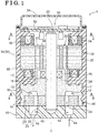
- an electric pump 1 is constructed by a motor portion 30, a pump portion 10 driven by the motor portion 30, a control portion 50 controlling the motor portion 30, and a resin portion 60 provided at outer peripheries of the motor portion 30 and the pump portion 10 to extend from the motor portion 30 to the pump portion 10.
- the electric pump 1 is employed for pumping lubricant at an engine of a vehicle as hydraulic oil to hydraulic equipment.
- the electric pump 1 may be applied to a hydraulic device of other than the vehicle.
- a medicine or a chemical substance in liquid form may be used as a pumping object, for example.
- the hydraulic oil serves as an example of hydraulic fluid.
- the pump portion 10 includes a pump housing 11, an internal gear pump 21 and a pump cover 40.
- the internal gear pump 21 serves as an example of a gear pump.
- the pump housing 11 is made of ferrous metallic material.
- the pump housing 11 includes a columnar outer configuration.
- a housing portion 14 including a bottom and a circular cross-section is provided at an end surface of the pump housing 11 facing the pump cover 40.
- a protruding portion 15 in a cylindrical form is provided at an opposite end surface from the housing portion 14.
- An oil seal 26 is inserted to be positioned at an inner side of the protruding portion 15.
- An inlet port 12 and an outlet port 13 are provided at a bottom surface of the housing portion 14.
- a bearing bore 17 is provided at a center of the pump housing 11. As illustrated in Fig. 2 , an axis of the housing portion 14 is eccentric to an axis X of the bearing bore 17.
- a rotary shaft 25 is inserted to be positioned within the bearing bore 17 in a state penetrating through the oil seal 26, the bearing bore 17 and an inner rotor 22 of the internal gear pump 21.
- the rotary shaft 25 is rotatably supported at the bearing bore 17.
- An axis of the rotary shaft 25 and an axis of the inner rotor 22 are both coaxial with the axis X.
- the rotary shaft 25 and the inner rotor 22 integrally rotate with each other.
- the "coaxiality" in the embodiment does not only mean that displacement of plural axes (which is hereinafter referred to as concentricity) is zero but also mean that the concentricity is approximately zero including zero.
- the internal gear pump 21 which is housed in the housing portion 14 includes the inner rotor 22 and an outer rotor 23.
- Each of the inner rotor 22 and the outer rotor 23 is made of ferrous metallic material.
- the internal gear pump 21 is constructed so that outer teeth provided at the inner rotor 22 and inner teeth provided at the outer rotor 23 are meshed with one another.
- the outer rotor 23 rotates around the inner rotor 22 by following the rotation of the inner rotor 22.
- Plural pump chambers 24 of which volumes increase and decrease depending on the rotation are defined between a teeth portion of the inner rotor 22 and a teeth portion of the outer rotor 23.
- the pump cover 40 is made of resin and is arranged adjacent to the pump housing 11.
- the pump cover 40 is joined to the resin portion 60 which is explained later by welding, for example.
- the pump cover 40 includes the same outer diameter as the resin portion 60.
- the pump cover 40 and the resin portion 60 are joined and integrated so that the internal gear pump 21 is held within the housing portion 14.
- the pump cover 40 includes an inlet port 42 at a side opposite to the inlet port 12 relative to the housing portion 14 and an outlet port 43 at a side opposite to the outlet port 13 relative to the housing portion 14.
- An inlet passage 44 extends outward from the inlet port 42 and an outlet passage 45 extends outward from the outlet port 43.
- the inlet port 42 is a curved groove and is provided communicating with the pump chambers 24 of the internal gear pump 21 along a range where the volumes of the pump chambers 24 of the internal gear pump 21 increase.
- the outlet port 43 is also a curved groove and is provided communicating with the pump chambers 24 of the internal gear pump 21 along a range where the volumes of the pump chambers 24 of the internal gear pump 21 decrease.
- the inlet port 12 includes the same configuration and the same size as the inlet port 42.
- the outlet port 13 includes the same configuration and the same size as the outlet port 43.
- the motor portion 30 is arranged adjacent to the pump portion 10 in a direction along the axis X.
- the motor portion 30 includes a sensorless brushless DC motor 31.
- the sensorless brushless DC motor 31 is constructed by a rotor 36 in a cylindrical form and a stator 32 in a cylindrical form, the stator 32 being arranged at an outer periphery of the rotor 36 with a small clearance therebetween in a radial direction.
- the rotor 36 and the stator 32 are both coaxial with the axis X.
- the stator 32 includes an outermost diameter which is the same value as an outermost diameter of the pump housing 11.
- the rotor 36 is obtained by a magnet 38 embedded and fixed in a rotor core 37 including a cylindrical form, the rotor core 37 being formed by laminated magnetic steel sheets.
- the rotor 36 integrally rotates with the rotary shaft 25.
- the stator 32 includes a stator core 33 formed by laminated magnetic steel sheets, a coil support frame 35 formed by an insulator such as resin, for example, which covers teeth of the stator core 33, and a coil 34 wound at the teeth from above the coil support frame 35.
- the coil 34 constitutes a three-phase winding, each phase of the coil 34 being applied with a three-phase alternating current by an electric power supply from the control portion 50 at an outside which is explained later.
- the sensorless brushless DC motor 31 does not include a magnetic pole sensor such as a Hall element, for example.
- the sensorless brushless DC motor 31 detects a rotation position of the rotor 36 by utilizing an induced voltage induced to the coil 34 by the rotation of the rotor 36 and switches the power supply to the phases of the three-phase winding based on magnetic position information obtained on a basis of the rotation position of the rotor 36.
- the teeth of the stator core 33 magnetized by the power supply to the coil 34 and the magnet 38 are repeatedly suctioned and repelled to thereby rotate the rotor 36.
- the inner rotor 22 rotates via the rotary shaft 25. Accordingly, the stator 32 applies a rotation drive force to the rotor 36.
- the control portion 50 is arranged adjacent to the motor portion 30 in the direction along the axis X. As illustrated in Fig. 1 , the control portion 50 is constructed by implementation of an electric power control element, a capacitor, a resistor and a control component such as a motor driver for deciding timing of power control, for example, on a control board 52.
- the control board 52 is mounted and fixed to the resin portion 60 which is explained later by screwing, for example.
- the control portion 50 functions to generate a rotating magnetic field by sequentially supplying the electric power to the coil 34 so as to control a rotating speed of the rotor 36 by controlling a rotation speed of the rotating magnetic field.
- the control portion 50 is covered by a cover member 54 mounted to the resin portion 60 by welding, for example.
- the resin portion 60 is provided at outer peripheral surfaces of the stator 32 of the motor portion 30 and the pump housing 11 of the pump portion 10 to extend from the stator 32 to the pump housing 11.
- the resin portion 60 surrounds the outer peripheral surface of the pump housing 11 and surrounds the stator core 33 except for a part of the teeth thereof facing the rotor 36, the coil 34 and the entire coil support frame 35.
- a thickness of resin of the resin portion 60 at a radially outer side of an outermost circumference of the stator 32 and of an outermost circumference of the pump housing 11 is constant.
- the motor portion 30 and the pump portion 10 are integrated by the resin portion 60.
- the resin portion 60 is formed by insert molding at the stator 32 and the pump housing 11.
- Plural groove portions 16 each of which includes an annular form are provided at an outer surface of the pump housing 11.
- the resin of the resin portion 60 is fitted into the groove portions 16.
- the groove portions 16 are provided at the pump hosing 11.
- knurls including shallower groove portions than the groove portions 16 may be provided.
- the resin of the resin portion 6 is also fitted into the groove portions of the knurls to thereby firmly fix the resin portion 60 and the pump housing 11 to each other.
- Each of the groove portions 16 and the groove portions of the knurls serves as an example of a recess portion.
- the hydraulic oil hardly leaks to the outside of the electric pump 1 by flowing through a boundary between the pump housing 11 and the resin portion 60 even if the hydraulic oil flows from the internal gear pump 21 through a clearance between the rotary shaft 25 and the bearing 17 and leaks from the oil seal 26. This is because the hydraulic oil leaking from the oil seal 26 reaches the outside of the electric pump 1 via the groove portions 16 when flowing through the boundary between the pump housing 11 and the resin portion 60, a creepage distance by which the hydraulic oil reaches the outside of the electric pump 1 is elongated as compared to a case where the groove portions 16 are not provided.
- the electric pump 1 may be constructed at a low cost accordingly.
- the coil 34 of the stator 32 is applied with the three-phase alternating current by a command from the control portion 50 to thereby rotate the rotor 36.
- the inner rotor 22 of the internal gear pump 21 rotates via the rotary shaft 25.
- the outer rotor 23 which is meshed with the inner rotor 22 rotates by following the rotation of the inner rotor 22.
- the volumes of the pump chambers 24 increase within the range where the pump chambers 24 are in communication with the inlet ports 42 and 12 and decrease within the range where the pump chambers 24 are in communication with the outlet ports 43 and 13 based on the rotations of the inner rotor 22 and the outer rotor 23.
- the hydraulic oil which flows through the inlet passage 44 is suctioned to the pump chambers 24 from the inlet port 42 by a negative pressure and is thereafter pumped out to the outlet port 43 from the inlet port 42 by a positive pressure so as to flow through the outlet passage 45 by being discharged from the outlet port 43.
- An assembly process of the electric pump 1 is characterized by the resin portion 60 which is formed by insert molding at the stator 32 and the pump housing 11.
- the other processes such as an assembly of the rotor 36, an assembly of the stator 32, an assembly of the control portion 50 and a mounting of the internal gear pump 21 to the pump housing 11, for example, are known and therefore detailed explanation is omitted.
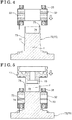
- Figs. 4 to 8 illustrate a process for forming the resin portion 60 by insert molding at the stator 32 and the pump housing 11.
- the stator 32 is placed onto a fixed die 72 of a forming die 70, the forming die 70 consisting of the fixed die 72 and a movable die 78.
- the fixed die 72 includes a stator contact portion 73 in a column form, a step 74 provided at a lower end of the stator contact portion 73, and a dent 76 provided at an upper surface 75 and including a circular cross-section in a direction orthogonal to an axis of the fixed die 72. Because the fixed die 72 is processed by cutting, for example, processing accuracy is extremely high.
- each of the axis of the stator contact portion 73 and the axis of the dent 76 is referred to as an axis Y.
- an inner peripheral surface of the stator 32 makes contact with an outer peripheral surface of the stator contact portion 73. Accordingly, an axis of the stator 32 and the axis Y of the stator contact portion 73 match each other to achieve positioning in the radial direction.
- an inner diameter of the coil support frame 35 is slightly greater than an inner diameter of the stator core 33.
- the step 74 is provided corresponding to a difference between the aforementioned inner diameters.
- the pump housing 11 is placed onto the fixed die 72 so that the protruding portion 15 is fitted in the dent 76.
- the inner diameter of the dent 76 is substantially equal to an outer diameter of the protruding portion 15 of the pump housing 11.
- an outer peripheral surface of the protruding portion 15 makes contact with an inner peripheral surface of the dent 76. Accordingly, an axis of the pump housing 11 and the axis Y of the fixed die 72 match each other to achieve positioning in the radial direction.
- a surface at a radially outer side than the protruding portion 15 in the pump housing 11 makes contact with the upper surface 75 so that the pump housing 11 is positioned relative to the fixed die 72 in the direction along the axis Y.
- the axis of the stator 32 and the axis of the pump housing 11 both match the axis Y of the fixed die 72.
- the outermost diameter of the stator 32 is the same as the outermost diameter of the pump housing 11.
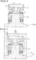
- thermoplastic resin such as polyphenylene sulfide (PPS) resin, for example, is brought to flow into the forming die 70 from a gate 79.
- PPS polyphenylene sulfide
- the resin is cooled and hardened in the closed die.
- the hardened thermoplastic resin forms the resin portion 60. Because the outermost diameter of the stator 32 is the same as the outermost diameter of the pump housing 11, flow resistance when the resin fills the forming die 70 is small to thereby increase filling ability.
- a thickness of the resin portion 60 in the radial direction thereof may be easily constant. With the constant thickness of the resin portion 60, an entire periphery of the resin portion 60 is evenly cooled so that shrinkage of the resin portion 60 may be unlikely to occur and displacement of the axes of the stator 32 and the pump housing 11 may be unlikely to occur after cooling of the resin portion 60.
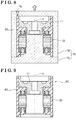
- the forming die 70 is opened to take out an intermediate assembly 80 which is obtained by the stator 32 and the pump housing 11 which are integrated by the resin portion 60 as illustrated in Fig. 9 . Even in the state of the intermediate assembly 80, the axis of the stator 32 and the axis of the pump housing 11 maintain matching each other.
- the oil seal 26, the rotor 36 into which the rotary shaft 25 is inserted to be positioned, and the internal gear pump 21 are assembled on the intermediate assembly 80.
- the pump cover 40 is then joined to an end portion of the resin portion 60 by welding, for example.
- the control portion 50 is assembled on the resin portion 60 and the cover member 54 is joined to an end portion of the resin portion 60 by welding, for example. As a result, the electric pump 1 is completed.
- the resin portion 60 is formed by insert molding to integrate the stator 32 and the pump housing 11.
- the axis of the stator 32 and the axis of the pump housing 11 are maintained matching each other.
- the concentricity between the axis of the stator 32 and the axis of the pump housing 11 at the electric pump 1 is greatly reduced as compared to the concentricity between an axis of a motor portion and an axis of a pump portion in a case where the motor portion and the pump portion are separately produced so that a recess portion and a projection of the motor portion and the pump portion are fitted in a spigot structure.
- the concentricity between the motor portion 30 and the pump portion 10 decreases, the concentricity between the axis of the stator 32 of the motor portion 30 and an axis of the rotor 36 where the rotary shaft 25 is inserted to be positioned within the bearing bore 17 of the pump portion 10 decreases.
- an air gap between the stator 32 and the rotor 36 may decrease to thereby improve driving efficiency of the motor. That is, with the same driving efficiency, an amount of usage of the magnet 38 employed at the rotor 36 may decrease.
- the outer peripheral surface of the pump housing 11 made of ferrous metallic material is covered by the resin portion 60 so that the outer peripheral surface of the pump housing 11 is inhibited from making contact with air.
- the pump housing 11 is therefore inhibited from being corroded.
- performance and lifetime of the electric pump 1 are inhibited from decreasing, which may lead to stable performance of the electric pump 1 for a long period of time.
- the resin portion 60 extends along the axial direction to an end surface of the pump housing 11 at a side facing the pump cover 40.
- the pump cover 40 formed by the resin is joined to the resin portion 60 by welding, for example, so that a bolt which is employed for joining a pump cover at a known electric pump is not necessary.
- a bore through which the bolt is inserted to be positioned or a protruding portion at a radially outer side where an internal thread is provided for fixing the bolt is not necessary.
- the electric pump 1 may be produced at a reduced cost and a reduced size.
- the present invention is applicable to an electric pump and a method for producing the same.
Landscapes
- Engineering & Computer Science (AREA)
- Mechanical Engineering (AREA)
- General Engineering & Computer Science (AREA)
- Rotary Pumps (AREA)
- Details And Applications Of Rotary Liquid Pumps (AREA)
Applications Claiming Priority (2)
| Application Number | Priority Date | Filing Date | Title |
|---|---|---|---|
| JP2015179800A JP6597091B2 (ja) | 2015-09-11 | 2015-09-11 | 電動ポンプとその製造方法 |
| PCT/JP2016/076012 WO2017043444A1 (ja) | 2015-09-11 | 2016-09-05 | 電動ポンプとその製造方法 |
Publications (3)
| Publication Number | Publication Date |
|---|---|
| EP3348837A1 true EP3348837A1 (de) | 2018-07-18 |
| EP3348837A4 EP3348837A4 (de) | 2018-08-08 |
| EP3348837B1 EP3348837B1 (de) | 2024-09-04 |
Family
ID=58240911
Family Applications (1)
| Application Number | Title | Priority Date | Filing Date |
|---|---|---|---|
| EP16844305.9A Active EP3348837B1 (de) | 2015-09-11 | 2016-09-05 | Elektrische pumpe und verfahren zur herstellung davon |
Country Status (5)
| Country | Link |
|---|---|
| US (1) | US20180238325A1 (de) |
| EP (1) | EP3348837B1 (de) |
| JP (1) | JP6597091B2 (de) |
| CN (1) | CN107923389B (de) |
| WO (1) | WO2017043444A1 (de) |
Cited By (1)
| Publication number | Priority date | Publication date | Assignee | Title |
|---|---|---|---|---|
| CN109873532A (zh) * | 2019-04-24 | 2019-06-11 | 兰州理工大学 | 一种复合式齿轮马达发电机 |
Families Citing this family (12)
| Publication number | Priority date | Publication date | Assignee | Title |
|---|---|---|---|---|
| US11070106B2 (en) | 2017-07-31 | 2021-07-20 | Nidec Tosok Corporation | Electric oil pump |
| CN208571864U (zh) | 2017-07-31 | 2019-03-01 | 日本电产东测有限公司 | 马达 |
| JP6668313B2 (ja) * | 2017-12-13 | 2020-03-18 | 株式会社不二工機 | 排水ポンプ用モータおよびその製造方法、ならびにそのモータを有する排水ポンプ |
| JP6546984B1 (ja) * | 2017-12-27 | 2019-07-17 | Kyb株式会社 | 電動液圧アクチュエータ |
| DE102018208853A1 (de) * | 2018-06-05 | 2019-12-05 | Magna Powertrain Bad Homburg GmbH | Pumpe |
| CN110857689B (zh) * | 2018-08-24 | 2021-10-19 | 杭州三花研究院有限公司 | 电动泵 |
| CN111852848A (zh) * | 2019-04-25 | 2020-10-30 | 杭州三花研究院有限公司 | 油泵 |
| CN109944796A (zh) * | 2019-04-25 | 2019-06-28 | 杭州三花研究院有限公司 | 油泵 |
| KR20220045754A (ko) * | 2020-10-06 | 2022-04-13 | 엘지이노텍 주식회사 | 전동 펌프 |
| CN114837792A (zh) | 2021-03-10 | 2022-08-02 | 美普盛(上海)汽车零部件有限公司 | 一种带膨胀补偿密封件的电动冷却液泵 |
| DE102022128264A1 (de) * | 2022-10-25 | 2024-04-25 | Valeo Powertrain Gmbh | Zahnradpumpe |
| JP2025144590A (ja) * | 2024-03-20 | 2025-10-03 | 豊田合成株式会社 | 電動液体ポンプ |
Family Cites Families (14)
| Publication number | Priority date | Publication date | Assignee | Title |
|---|---|---|---|---|
| JPS63227980A (ja) * | 1987-03-16 | 1988-09-22 | Toshiba Corp | ポンプ |
| JP2007009787A (ja) * | 2005-06-30 | 2007-01-18 | Hitachi Ltd | モータ一体型内接歯車式ポンプ及び電子機器 |
| JP4760503B2 (ja) * | 2006-04-07 | 2011-08-31 | パナソニック電工株式会社 | ポンプ及びポンプの製造方法 |
| JP2008086117A (ja) * | 2006-09-27 | 2008-04-10 | Aisin Seiki Co Ltd | 電動式流体ポンプ |
| JP5216038B2 (ja) * | 2010-03-25 | 2013-06-19 | 株式会社日立製作所 | 回転電動機 |
| JP2012072558A (ja) * | 2010-09-27 | 2012-04-12 | Panasonic Corp | 操作レバー式混合水栓 |
| CN102477990B (zh) * | 2010-11-26 | 2015-05-27 | 上海日立电器有限公司 | 一种转子式压缩机的吸气结构 |
| JP5927766B2 (ja) * | 2011-03-11 | 2016-06-01 | 株式会社ジェイテクト | 電動ポンプユニット |
| JP6056149B2 (ja) * | 2011-08-31 | 2017-01-11 | 株式会社ジェイテクト | 電動ポンプユニットおよびその製造方法 |
| JP5987331B2 (ja) * | 2012-02-02 | 2016-09-07 | 株式会社ジェイテクト | 電動オイルポンプ装置 |
| JP2013244649A (ja) * | 2012-05-24 | 2013-12-09 | Keihin Corp | 複合部材及びそれを使用する電磁弁,並びに複合部材の製造方法 |
| JP6028406B2 (ja) * | 2012-06-15 | 2016-11-16 | 株式会社ジェイテクト | 電動ポンプ装置 |
| DE102013204071A1 (de) * | 2013-03-11 | 2014-09-11 | Robert Bosch Gmbh | Innenzahnradpumpe |
| JP6248487B2 (ja) * | 2013-09-12 | 2017-12-20 | 株式会社ジェイテクト | 電動ポンプ装置 |
-
2015
- 2015-09-11 JP JP2015179800A patent/JP6597091B2/ja not_active Expired - Fee Related
-
2016
- 2016-09-05 EP EP16844305.9A patent/EP3348837B1/de active Active
- 2016-09-05 US US15/751,937 patent/US20180238325A1/en not_active Abandoned
- 2016-09-05 WO PCT/JP2016/076012 patent/WO2017043444A1/ja not_active Ceased
- 2016-09-05 CN CN201680047516.9A patent/CN107923389B/zh not_active Expired - Fee Related
Cited By (2)
| Publication number | Priority date | Publication date | Assignee | Title |
|---|---|---|---|---|
| CN109873532A (zh) * | 2019-04-24 | 2019-06-11 | 兰州理工大学 | 一种复合式齿轮马达发电机 |
| CN109873532B (zh) * | 2019-04-24 | 2020-12-29 | 兰州理工大学 | 一种复合式齿轮马达发电机 |
Also Published As
| Publication number | Publication date |
|---|---|
| CN107923389A (zh) | 2018-04-17 |
| EP3348837B1 (de) | 2024-09-04 |
| WO2017043444A1 (ja) | 2017-03-16 |
| JP6597091B2 (ja) | 2019-10-30 |
| JP2017053323A (ja) | 2017-03-16 |
| US20180238325A1 (en) | 2018-08-23 |
| CN107923389B (zh) | 2020-03-27 |
| EP3348837A4 (de) | 2018-08-08 |
Similar Documents
| Publication | Publication Date | Title |
|---|---|---|
| EP3348837B1 (de) | Elektrische pumpe und verfahren zur herstellung davon | |
| EP2379892B1 (de) | Vollständig untertauchbare integrierte elektroölpumpe | |
| JP5474117B2 (ja) | 電動ポンプ、及び電動ポンプの製造方法 | |
| US10012220B2 (en) | Magnetically driven pump arrangement having a micropump with forced flushing, and operating method | |
| US9163626B2 (en) | Gear pump | |
| CN107787409B (zh) | 流体泵 | |
| CN110311503B (zh) | 马达及车辆 | |
| JP5511770B2 (ja) | 電動ポンプ、及び電動ポンプの製造方法 | |
| JP5880842B2 (ja) | 電動オイルポンプ装置 | |
| US9954415B2 (en) | Rotor for brushless motor | |
| EP2811168A1 (de) | Pumpe, kältekreislaufvorrichtung und verfahren zur herstellung der pumpe | |
| JP2015055201A (ja) | 電動ポンプユニット | |
| JP2013150403A (ja) | モータ装置およびその製造方法 | |
| EP2811167A1 (de) | Pumpe, kältekreislaufvorrichtung und verfahren zur herstellung der pumpe | |
| WO2009126853A2 (en) | Rotor assembly including sintered magnet core assembly | |
| EP3345289B1 (de) | Hilfsvorrichtung mit elektrischem antriebsmotor für fahrzeug | |
| JP6489183B2 (ja) | ステータ、その製造方法、そのステータを用いたモータ及び圧縮機 | |
| JP2013241837A (ja) | 電動ポンプ | |
| US20250101981A1 (en) | Pump assembly | |
| EP2770214A2 (de) | Elektrische Flüssigkeitspumpe | |
| EP3542453B1 (de) | Elektrische kfz-flüssigkeitspumpe | |
| JP6621627B2 (ja) | マイクロポンプ | |
| US20260005566A1 (en) | Rotor assembly for an electric pump device | |
| JP2013249817A (ja) | 電動オイルポンプ装置 | |
| JP2010138850A (ja) | 電動ポンプ |
Legal Events
| Date | Code | Title | Description |
|---|---|---|---|
| STAA | Information on the status of an ep patent application or granted ep patent |
Free format text: STATUS: THE INTERNATIONAL PUBLICATION HAS BEEN MADE |
|
| PUAI | Public reference made under article 153(3) epc to a published international application that has entered the european phase |
Free format text: ORIGINAL CODE: 0009012 |
|
| STAA | Information on the status of an ep patent application or granted ep patent |
Free format text: STATUS: REQUEST FOR EXAMINATION WAS MADE |
|
| 17P | Request for examination filed |
Effective date: 20180212 |
|
| AK | Designated contracting states |
Kind code of ref document: A1 Designated state(s): AL AT BE BG CH CY CZ DE DK EE ES FI FR GB GR HR HU IE IS IT LI LT LU LV MC MK MT NL NO PL PT RO RS SE SI SK SM TR |
|
| AX | Request for extension of the european patent |
Extension state: BA ME |
|
| A4 | Supplementary search report drawn up and despatched |
Effective date: 20180709 |
|
| RIC1 | Information provided on ipc code assigned before grant |
Ipc: F04C 2/08 20060101ALI20180703BHEP Ipc: F04C 2/18 20060101ALI20180703BHEP Ipc: F04C 2/10 20060101AFI20180703BHEP Ipc: F04C 15/00 20060101ALI20180703BHEP |
|
| DAV | Request for validation of the european patent (deleted) | ||
| DAX | Request for extension of the european patent (deleted) | ||
| STAA | Information on the status of an ep patent application or granted ep patent |
Free format text: STATUS: EXAMINATION IS IN PROGRESS |
|
| 17Q | First examination report despatched |
Effective date: 20210701 |
|
| RAP3 | Party data changed (applicant data changed or rights of an application transferred) |
Owner name: AISIN CORPORATION |
|
| GRAP | Despatch of communication of intention to grant a patent |
Free format text: ORIGINAL CODE: EPIDOSNIGR1 |
|
| STAA | Information on the status of an ep patent application or granted ep patent |
Free format text: STATUS: GRANT OF PATENT IS INTENDED |
|
| INTG | Intention to grant announced |
Effective date: 20240517 |
|
| GRAS | Grant fee paid |
Free format text: ORIGINAL CODE: EPIDOSNIGR3 |
|
| GRAA | (expected) grant |
Free format text: ORIGINAL CODE: 0009210 |
|
| STAA | Information on the status of an ep patent application or granted ep patent |
Free format text: STATUS: THE PATENT HAS BEEN GRANTED |
|
| AK | Designated contracting states |
Kind code of ref document: B1 Designated state(s): AL AT BE BG CH CY CZ DE DK EE ES FI FR GB GR HR HU IE IS IT LI LT LU LV MC MK MT NL NO PL PT RO RS SE SI SK SM TR |
|
| REG | Reference to a national code |
Ref country code: GB Ref legal event code: FG4D |
|
| REG | Reference to a national code |
Ref country code: CH Ref legal event code: EP |
|
| REG | Reference to a national code |
Ref country code: IE Ref legal event code: FG4D |
|
| REG | Reference to a national code |
Ref country code: DE Ref legal event code: R096 Ref document number: 602016089276 Country of ref document: DE |
|
| REG | Reference to a national code |
Ref country code: LT Ref legal event code: MG9D |
|
| REG | Reference to a national code |
Ref country code: NL Ref legal event code: MP Effective date: 20240904 |
|
| PG25 | Lapsed in a contracting state [announced via postgrant information from national office to epo] |
Ref country code: NO Free format text: LAPSE BECAUSE OF FAILURE TO SUBMIT A TRANSLATION OF THE DESCRIPTION OR TO PAY THE FEE WITHIN THE PRESCRIBED TIME-LIMIT Effective date: 20241204 |
|
| PG25 | Lapsed in a contracting state [announced via postgrant information from national office to epo] |
Ref country code: PL Free format text: LAPSE BECAUSE OF FAILURE TO SUBMIT A TRANSLATION OF THE DESCRIPTION OR TO PAY THE FEE WITHIN THE PRESCRIBED TIME-LIMIT Effective date: 20240904 Ref country code: GR Free format text: LAPSE BECAUSE OF FAILURE TO SUBMIT A TRANSLATION OF THE DESCRIPTION OR TO PAY THE FEE WITHIN THE PRESCRIBED TIME-LIMIT Effective date: 20241205 Ref country code: FI Free format text: LAPSE BECAUSE OF FAILURE TO SUBMIT A TRANSLATION OF THE DESCRIPTION OR TO PAY THE FEE WITHIN THE PRESCRIBED TIME-LIMIT Effective date: 20240904 |
|
| PG25 | Lapsed in a contracting state [announced via postgrant information from national office to epo] |
Ref country code: BG Free format text: LAPSE BECAUSE OF FAILURE TO SUBMIT A TRANSLATION OF THE DESCRIPTION OR TO PAY THE FEE WITHIN THE PRESCRIBED TIME-LIMIT Effective date: 20240904 |
|
| PG25 | Lapsed in a contracting state [announced via postgrant information from national office to epo] |
Ref country code: LV Free format text: LAPSE BECAUSE OF FAILURE TO SUBMIT A TRANSLATION OF THE DESCRIPTION OR TO PAY THE FEE WITHIN THE PRESCRIBED TIME-LIMIT Effective date: 20240904 |
|
| PG25 | Lapsed in a contracting state [announced via postgrant information from national office to epo] |
Ref country code: HR Free format text: LAPSE BECAUSE OF FAILURE TO SUBMIT A TRANSLATION OF THE DESCRIPTION OR TO PAY THE FEE WITHIN THE PRESCRIBED TIME-LIMIT Effective date: 20240904 |
|
| PG25 | Lapsed in a contracting state [announced via postgrant information from national office to epo] |
Ref country code: ES Free format text: LAPSE BECAUSE OF FAILURE TO SUBMIT A TRANSLATION OF THE DESCRIPTION OR TO PAY THE FEE WITHIN THE PRESCRIBED TIME-LIMIT Effective date: 20240904 Ref country code: RS Free format text: LAPSE BECAUSE OF FAILURE TO SUBMIT A TRANSLATION OF THE DESCRIPTION OR TO PAY THE FEE WITHIN THE PRESCRIBED TIME-LIMIT Effective date: 20241204 |
|
| PG25 | Lapsed in a contracting state [announced via postgrant information from national office to epo] |
Ref country code: RS Free format text: LAPSE BECAUSE OF FAILURE TO SUBMIT A TRANSLATION OF THE DESCRIPTION OR TO PAY THE FEE WITHIN THE PRESCRIBED TIME-LIMIT Effective date: 20241204 Ref country code: PL Free format text: LAPSE BECAUSE OF FAILURE TO SUBMIT A TRANSLATION OF THE DESCRIPTION OR TO PAY THE FEE WITHIN THE PRESCRIBED TIME-LIMIT Effective date: 20240904 Ref country code: NO Free format text: LAPSE BECAUSE OF FAILURE TO SUBMIT A TRANSLATION OF THE DESCRIPTION OR TO PAY THE FEE WITHIN THE PRESCRIBED TIME-LIMIT Effective date: 20241204 Ref country code: LV Free format text: LAPSE BECAUSE OF FAILURE TO SUBMIT A TRANSLATION OF THE DESCRIPTION OR TO PAY THE FEE WITHIN THE PRESCRIBED TIME-LIMIT Effective date: 20240904 Ref country code: HR Free format text: LAPSE BECAUSE OF FAILURE TO SUBMIT A TRANSLATION OF THE DESCRIPTION OR TO PAY THE FEE WITHIN THE PRESCRIBED TIME-LIMIT Effective date: 20240904 Ref country code: GR Free format text: LAPSE BECAUSE OF FAILURE TO SUBMIT A TRANSLATION OF THE DESCRIPTION OR TO PAY THE FEE WITHIN THE PRESCRIBED TIME-LIMIT Effective date: 20241205 Ref country code: FI Free format text: LAPSE BECAUSE OF FAILURE TO SUBMIT A TRANSLATION OF THE DESCRIPTION OR TO PAY THE FEE WITHIN THE PRESCRIBED TIME-LIMIT Effective date: 20240904 Ref country code: ES Free format text: LAPSE BECAUSE OF FAILURE TO SUBMIT A TRANSLATION OF THE DESCRIPTION OR TO PAY THE FEE WITHIN THE PRESCRIBED TIME-LIMIT Effective date: 20240904 Ref country code: BG Free format text: LAPSE BECAUSE OF FAILURE TO SUBMIT A TRANSLATION OF THE DESCRIPTION OR TO PAY THE FEE WITHIN THE PRESCRIBED TIME-LIMIT Effective date: 20240904 |
|
| REG | Reference to a national code |
Ref country code: AT Ref legal event code: MK05 Ref document number: 1720655 Country of ref document: AT Kind code of ref document: T Effective date: 20240904 |
|
| PG25 | Lapsed in a contracting state [announced via postgrant information from national office to epo] |
Ref country code: NL Free format text: LAPSE BECAUSE OF FAILURE TO SUBMIT A TRANSLATION OF THE DESCRIPTION OR TO PAY THE FEE WITHIN THE PRESCRIBED TIME-LIMIT Effective date: 20240904 |
|
| PG25 | Lapsed in a contracting state [announced via postgrant information from national office to epo] |
Ref country code: PT Free format text: LAPSE BECAUSE OF FAILURE TO SUBMIT A TRANSLATION OF THE DESCRIPTION OR TO PAY THE FEE WITHIN THE PRESCRIBED TIME-LIMIT Effective date: 20250106 Ref country code: IS Free format text: LAPSE BECAUSE OF FAILURE TO SUBMIT A TRANSLATION OF THE DESCRIPTION OR TO PAY THE FEE WITHIN THE PRESCRIBED TIME-LIMIT Effective date: 20250104 |
|
| PG25 | Lapsed in a contracting state [announced via postgrant information from national office to epo] |
Ref country code: SM Free format text: LAPSE BECAUSE OF FAILURE TO SUBMIT A TRANSLATION OF THE DESCRIPTION OR TO PAY THE FEE WITHIN THE PRESCRIBED TIME-LIMIT Effective date: 20240904 Ref country code: RO Free format text: LAPSE BECAUSE OF FAILURE TO SUBMIT A TRANSLATION OF THE DESCRIPTION OR TO PAY THE FEE WITHIN THE PRESCRIBED TIME-LIMIT Effective date: 20240904 |
|
| PG25 | Lapsed in a contracting state [announced via postgrant information from national office to epo] |
Ref country code: EE Free format text: LAPSE BECAUSE OF FAILURE TO SUBMIT A TRANSLATION OF THE DESCRIPTION OR TO PAY THE FEE WITHIN THE PRESCRIBED TIME-LIMIT Effective date: 20240904 Ref country code: AT Free format text: LAPSE BECAUSE OF FAILURE TO SUBMIT A TRANSLATION OF THE DESCRIPTION OR TO PAY THE FEE WITHIN THE PRESCRIBED TIME-LIMIT Effective date: 20240904 |
|
| PG25 | Lapsed in a contracting state [announced via postgrant information from national office to epo] |
Ref country code: CZ Free format text: LAPSE BECAUSE OF FAILURE TO SUBMIT A TRANSLATION OF THE DESCRIPTION OR TO PAY THE FEE WITHIN THE PRESCRIBED TIME-LIMIT Effective date: 20240904 |
|
| PG25 | Lapsed in a contracting state [announced via postgrant information from national office to epo] |
Ref country code: IT Free format text: LAPSE BECAUSE OF FAILURE TO SUBMIT A TRANSLATION OF THE DESCRIPTION OR TO PAY THE FEE WITHIN THE PRESCRIBED TIME-LIMIT Effective date: 20240904 Ref country code: SK Free format text: LAPSE BECAUSE OF FAILURE TO SUBMIT A TRANSLATION OF THE DESCRIPTION OR TO PAY THE FEE WITHIN THE PRESCRIBED TIME-LIMIT Effective date: 20240904 |
|
| REG | Reference to a national code |
Ref country code: CH Ref legal event code: PL |
|
| PG25 | Lapsed in a contracting state [announced via postgrant information from national office to epo] |
Ref country code: LU Free format text: LAPSE BECAUSE OF NON-PAYMENT OF DUE FEES Effective date: 20240905 |
|
| REG | Reference to a national code |
Ref country code: DE Ref legal event code: R097 Ref document number: 602016089276 Country of ref document: DE |
|
| PG25 | Lapsed in a contracting state [announced via postgrant information from national office to epo] |
Ref country code: MC Free format text: LAPSE BECAUSE OF FAILURE TO SUBMIT A TRANSLATION OF THE DESCRIPTION OR TO PAY THE FEE WITHIN THE PRESCRIBED TIME-LIMIT Effective date: 20240904 |
|
| PG25 | Lapsed in a contracting state [announced via postgrant information from national office to epo] |
Ref country code: DK Free format text: LAPSE BECAUSE OF FAILURE TO SUBMIT A TRANSLATION OF THE DESCRIPTION OR TO PAY THE FEE WITHIN THE PRESCRIBED TIME-LIMIT Effective date: 20240904 |
|
| REG | Reference to a national code |
Ref country code: BE Ref legal event code: MM Effective date: 20240930 |
|
| PLBE | No opposition filed within time limit |
Free format text: ORIGINAL CODE: 0009261 |
|
| STAA | Information on the status of an ep patent application or granted ep patent |
Free format text: STATUS: NO OPPOSITION FILED WITHIN TIME LIMIT |
|
| PG25 | Lapsed in a contracting state [announced via postgrant information from national office to epo] |
Ref country code: BE Free format text: LAPSE BECAUSE OF NON-PAYMENT OF DUE FEES Effective date: 20240930 |
|
| PG25 | Lapsed in a contracting state [announced via postgrant information from national office to epo] |
Ref country code: CH Free format text: LAPSE BECAUSE OF NON-PAYMENT OF DUE FEES Effective date: 20240930 |
|
| PG25 | Lapsed in a contracting state [announced via postgrant information from national office to epo] |
Ref country code: IE Free format text: LAPSE BECAUSE OF NON-PAYMENT OF DUE FEES Effective date: 20240905 |
|
| 26N | No opposition filed |
Effective date: 20250605 |
|
| GBPC | Gb: european patent ceased through non-payment of renewal fee |
Effective date: 20241204 |
|
| PG25 | Lapsed in a contracting state [announced via postgrant information from national office to epo] |
Ref country code: SE Free format text: LAPSE BECAUSE OF FAILURE TO SUBMIT A TRANSLATION OF THE DESCRIPTION OR TO PAY THE FEE WITHIN THE PRESCRIBED TIME-LIMIT Effective date: 20240904 |
|
| PGFP | Annual fee paid to national office [announced via postgrant information from national office to epo] |
Ref country code: DE Payment date: 20250730 Year of fee payment: 10 |
|
| PG25 | Lapsed in a contracting state [announced via postgrant information from national office to epo] |
Ref country code: GB Free format text: LAPSE BECAUSE OF NON-PAYMENT OF DUE FEES Effective date: 20241204 |
|
| PGFP | Annual fee paid to national office [announced via postgrant information from national office to epo] |
Ref country code: FR Payment date: 20250808 Year of fee payment: 10 |
|
| PG25 | Lapsed in a contracting state [announced via postgrant information from national office to epo] |
Ref country code: CY Free format text: LAPSE BECAUSE OF FAILURE TO SUBMIT A TRANSLATION OF THE DESCRIPTION OR TO PAY THE FEE WITHIN THE PRESCRIBED TIME-LIMIT; INVALID AB INITIO Effective date: 20160905 |
|
| PG25 | Lapsed in a contracting state [announced via postgrant information from national office to epo] |
Ref country code: HU Free format text: LAPSE BECAUSE OF FAILURE TO SUBMIT A TRANSLATION OF THE DESCRIPTION OR TO PAY THE FEE WITHIN THE PRESCRIBED TIME-LIMIT; INVALID AB INITIO Effective date: 20160905 |