EP3348978A1 - Temperaturmessvorrichtung mit thermoelement - Google Patents
Temperaturmessvorrichtung mit thermoelement Download PDFInfo
- Publication number
- EP3348978A1 EP3348978A1 EP17196965.2A EP17196965A EP3348978A1 EP 3348978 A1 EP3348978 A1 EP 3348978A1 EP 17196965 A EP17196965 A EP 17196965A EP 3348978 A1 EP3348978 A1 EP 3348978A1
- Authority
- EP
- European Patent Office
- Prior art keywords
- temperature
- casing
- cold junction
- thermocouple
- temperature sensor
- Prior art date
- Legal status (The legal status is an assumption and is not a legal conclusion. Google has not performed a legal analysis and makes no representation as to the accuracy of the status listed.)
- Granted
Links
Images


Classifications
-
- G—PHYSICS
- G01—MEASURING; TESTING
- G01K—MEASURING TEMPERATURE; MEASURING QUANTITY OF HEAT; THERMALLY-SENSITIVE ELEMENTS NOT OTHERWISE PROVIDED FOR
- G01K7/00—Measuring temperature based on the use of electric or magnetic elements directly sensitive to heat ; Power supply therefor, e.g. using thermoelectric elements
- G01K7/02—Measuring temperature based on the use of electric or magnetic elements directly sensitive to heat ; Power supply therefor, e.g. using thermoelectric elements using thermoelectric elements, e.g. thermocouples
- G01K7/10—Arrangements for compensating for auxiliary variables, e.g. length of lead
- G01K7/12—Arrangements with respect to the cold junction, e.g. preventing influence of temperature of surrounding air
-
- G—PHYSICS
- G01—MEASURING; TESTING
- G01K—MEASURING TEMPERATURE; MEASURING QUANTITY OF HEAT; THERMALLY-SENSITIVE ELEMENTS NOT OTHERWISE PROVIDED FOR
- G01K7/00—Measuring temperature based on the use of electric or magnetic elements directly sensitive to heat ; Power supply therefor, e.g. using thermoelectric elements
- G01K7/02—Measuring temperature based on the use of electric or magnetic elements directly sensitive to heat ; Power supply therefor, e.g. using thermoelectric elements using thermoelectric elements, e.g. thermocouples
- G01K7/10—Arrangements for compensating for auxiliary variables, e.g. length of lead
- G01K7/12—Arrangements with respect to the cold junction, e.g. preventing influence of temperature of surrounding air
- G01K7/13—Circuits for cold-junction compensation
-
- G—PHYSICS
- G01—MEASURING; TESTING
- G01K—MEASURING TEMPERATURE; MEASURING QUANTITY OF HEAT; THERMALLY-SENSITIVE ELEMENTS NOT OTHERWISE PROVIDED FOR
- G01K7/00—Measuring temperature based on the use of electric or magnetic elements directly sensitive to heat ; Power supply therefor, e.g. using thermoelectric elements
- G01K7/42—Circuits effecting compensation of thermal inertia; Circuits for predicting the stationary value of a temperature
- G01K7/427—Temperature calculation based on spatial modeling, e.g. spatial inter- or extrapolation
Definitions
- the present invention relates to a technology for measuring a temperature by using a thermocouple.
- thermocouple When a temperature is measured by using a thermocouple, there is a need to measure a cold junction temperature of the thermocouple by using a temperature sensor different from the thermocouple in addition to a temperature difference between a cold junction and a temperature measurement junction measured by the thermocouple.
- a temperature measurement device in which a connection terminal corresponding to a cold junction of a thermocouple is provided in a casing and a temperature sensor measuring a temperature of the connection terminal (the cold junction) is provided inside the casing is known (for example, see Patent Document 1).
- Patent Document 1 Japanese Unexamined Patent Application Publication No. 2001-124636
- the temperature sensor measuring the cold junction temperature is thermally influenced by heat generating components (a power supply and the like) inside the casing, the measured cold junction temperature may be different from an actual cold junction temperature. Further, since the temperature measurement device is used while being assembled to a host apparatus, the temperature measurement device can be easily damaged when there is a heat influence from heat generating components inside the host apparatus.
- an object of the invention is to provide a technology capable of improving an accuracy of temperature measurement using a thermocouple and managing an external temperature of a casing.
- a temperature measurement device using a thermocouple has the thermocouple externally connected thereto and includes a casing provided with a cold junction of the thermocouple, a first temperature sensor, a second temperature sensor, and a control unit.
- the first temperature sensor is disposed in a vicinity of the cold junction inside the casing and measures a cold junction temperature of the thermocouple.
- the second temperature sensor is disposed at a position different from the first temperature sensor inside the casing and measures an internal temperature of the casing. Then, the control unit calculates an external temperature of the casing on the basis of the cold junction temperature measured by the first temperature sensor and the internal temperature measured by the second temperature sensor.
- the temperature measurement device since the internal temperature of the casing is detected by the second temperature sensor and an influence of the internal temperature on the first temperature sensor is considered, it is possible to predict a temperature closer to an actual cold junction temperature than the cold junction temperature measured by the first temperature sensor as the cold junction temperature of the thermocouple. Further, it is possible to acquire the external temperature of the casing without additionally providing a temperature sensor at the outside of the casing by calculating the external temperature of the casing on the basis of the cold junction temperature and the internal temperature.
- the second temperature sensor is disposed in the vicinity of a heat generating component inside the casing. According to this configuration, since heat generated from the heat generating component can be easily transmitted to the second temperature sensor, a thermal influence of the heat generating component is reflected in the internal temperature measured by the second temperature sensor. Since such an internal temperature is used to predict the actual cold junction temperature, it is easy to exclude the thermal influence from the heat generating component and thus to acquire a temperature closer to the actual cold junction temperature than the cold junction temperature measured by the first temperature sensor.
- control unit can calculate the external temperature by using a difference between the cold junction temperature and the internal temperature.
- the control unit performs a notification using a notification unit in at least one of a case where the calculated external temperature is equal to or higher than a first threshold value and a case where the calculated external temperature is equal to or lower than a second threshold value.
- a first threshold value or the second threshold value is set to an appropriate value, it is possible to notify abnormality even when the temperature of the temperature measurement device is likely to be outside of or actually outside of an appropriate temperature range (for example, a rated temperature range) due to a certain influence.
- the control unit can calculate a temperature measurement junction temperature of the thermocouple by adding a temperature difference between the cold junction and a temperature measurement junction acquired from an input value from the thermocouple to the calculated external temperature of the casing. According to this configuration, since it is possible to commonize the external temperature calculation process and the cold junction temperature calculation process (for example, a correction process) used to calculate the temperature measurement junction temperature, the control of the temperature measurement device is simplified.
- thermocouple it is possible to improve the accuracy of temperature measurement using the thermocouple and to manage the external temperature of the casing.
- FIG. 1 is a conceptual diagram showing a temperature controller 1 according to an embodiment.
- the temperature controller 1 has a thermocouple 2 externally connected thereto and controls a temperature of a temperature control target (in this embodiment, a heating target which is a heater 31) while measuring the temperature of the temperature control target with the thermocouple 2.
- the temperature controller 1 includes a casing 10, a first temperature sensor 11, a second temperature sensor 12, a power supply unit 13, an output unit 14, a display unit 15, a control unit 16, a notification unit 17, and a storage unit 18.
- the casing 10 is provided with a connection terminal 10C to which the thermocouple 2 is connected to form a cold junction 21c of the thermocouple 2.
- the thermocouple 2 does not need to be connected to the connection terminal 10C and may be directly connected to, for example, a circuit board disposed inside the casing 10. In this case, a position connected to the circuit board becomes the cold junction 21c of the thermocouple 2. That is, the cold junction 21c of the thermocouple 2 may be disposed inside the casing 10 instead of outside of the casing 10.
- the first temperature sensor 11 is disposed in the vicinity of the cold junction 21c (in this embodiment, the connection terminal 10C) inside the casing 10 and measures a cold junction temperature Tc of the thermocouple 2.
- the first temperature sensor 11 measures the temperature of the connection terminal 10C as the cold junction temperature Tc.
- various temperature sensitive elements such as a diode can be used in the first temperature sensor 11.
- the first temperature sensor 11 is thermally influenced by a heat generating component like the power supply unit 13 or the output unit 14, the cold junction temperature Tc measured by the first temperature sensor 11 becomes a value larger than an actual cold junction temperature Tc0.
- the second temperature sensor 12 is disposed at a position different from the first temperature sensor 11 inside the casing 10 and measures the internal temperature Tin of the casing 10. Specifically, the second temperature sensor 12 is provided at a position where a temperature easily increases inside the casing 10. Further, as will be described later, it is desirable to dispose the second temperature sensor 12 in the vicinity of a heat generating component like the power supply unit 13 or the output unit 14 in order to improve the calculation accuracy of the external temperature Tout. For example, various temperature sensitive elements such as a diode can be used in the second temperature sensor 12.
- the power supply unit 13 supplies electric power to the components of the temperature controller 1.
- the power supply unit 13 includes a converting circuit which converts an AC voltage from a commercial power supply connected to the temperature controller 1 into a desired DC voltage.
- the output unit 14 is connected to an external device like the heater 31 or the blowing fan 32 and can control the external device in response to an instruction of the control unit 16.
- the output unit 14 includes an output circuit with a relay or a transistor and the external device is controlled by the output circuit when the control unit 16 controls the output circuit.
- the display unit 15 is provided in the temperature controller 1 while its display surface is exposed to the outside of the casing 10 (for example, the front surface). For example, the display unit 15 displays the measurement results of the thermocouple 2 or the external temperature Tout of the casing 10 to be described later.
- the control unit 16 is disposed inside the casing 10 and controls the output unit 14 on the basis of the measurement results of the thermocouple 2, thereby controlling the external device through the output unit 14.
- the heater 31 is connected to the output unit 14 and the temperature of the heater 31 is measured by the thermocouple 2.
- the control unit 16 can control the heater 31 through the output unit 14 so that the temperature of the heater 31 becomes a desired temperature.
- the blowing fan 32 may be further connected to the output unit 14. In this case, the control unit 16 can control the blowing fan 32 through the output unit 14 to forcedly decrease the temperature of the heater 31.
- a process (including a calculation process or the like to be described later) performed by the control unit 16 can be performed by, for example, a control processing device (not shown) such as a CPU (Central Processing Unit) or a microcomputer. Further, the process may be realized by executing a corresponding program using the temperature controller 1. Then, the same program may be stored in a storage medium (for example, a flash memory) or the storage unit 18 in a readable state.
- a control processing device such as a CPU (Central Processing Unit) or a microcomputer.
- the process may be realized by executing a corresponding program using the temperature controller 1. Then, the same program may be stored in a storage medium (for example, a flash memory) or the storage unit 18 in a readable state.
- control unit 16 further calculates the external temperature Tout of the casing 10 on the basis of the cold junction temperature Tc measured by the first temperature sensor 11 and the internal temperature Tin measured by the second temperature sensor 12.
- the control unit 16 calculates the external temperature Tout by applying the cold junction temperature Tc and the internal temperature Tin to Equation (1) below.
- Tout Tc ⁇ Tg
- Equation (1) is used to calculate the external temperature Tout by correcting the cold junction temperature Tc thermally influenced by a heat generating component using the correction amount Tg. Further, the correction amount Tg is based on a difference between the internal temperature Tin and the cold junction temperature Tc.
- an interpolation equation acquired by a linear interpolation for the measurement data is used as an equation for calculating the external temperature Tout, and reference symbols ⁇ and ⁇ respectively indicate a gradient and an intercept acquired by the linear interpolation. Further, an interpolation equation acquired by a polynomial interpolation for the measurement data may be used in an equation for calculating the external temperature Tout.
- the measurement temperature at a predetermined position outside the casing 10 and the cold junction temperature Tc and the internal temperature Tin corresponding to the measurement temperature are set as one set of measurement data and plural sets of the measurement data are acquired under at least two different conditions. Then, Equation (1) is acquired by performing a linear interpolation for the plural sets of measurement data. Further, it is desirable that a predetermined position (that is, a position at which the temperature is predicted by the calculated external temperature Tout) where the measurement temperature is measured be in the periphery of the casing 10. More specifically, it is desirable that the predetermined position be in the vicinity of the connection terminal 10C (for example, a position away from the connection terminal 10C by one to several cm).
- a different internal temperature Tin acquired by changing the internal heat generation amount (for example, the heat generation amount from a heat generating component) can be used.
- the measurement data is acquired under at least two conditions in which the internal temperature Tin is different and the interpolation equation is acquired from the measurement data.
- the internal temperatures Tin are different, but also the internal heat generation amount (for example, the heat generation amount from a heat generating component) which is maximum or minimum may be used.
- actual measurement data is acquired under two conditions in which the internal heat generation amount is different and the interpolation equation is acquired from the actual measurement data.
- the control unit 16 calculates the external temperature Tout by using the interpolation equation acquired from the actual measurement data.
- the interpolation equation used for calculating the external temperature Tout may be incorporated into a program or a program stored in the storage unit 18 may be read out and used by the control unit 16. Further, when the interpolation equation can be acquired from the actual measurement data based on a predetermined function (in the above-described example, a linear function), the predetermined function may be incorporated into a program in a form that allows the assignment of coefficients.
- the storage unit 18 stores only the coefficients of the interpolation equation acquired from the measurement data and the control unit 16 reads out the coefficients stored in the storage unit 18 and uses the coefficients at the time of calculating the external temperature Tout.
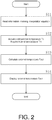
- FIG. 2 is a flowchart showing a process of calculating the external temperature Tout performed by the control unit 16.
- the control unit 16 reads information involving the interpolation equation from the storage unit 18 (step S11). As described above, when the interpolation equation is stored in the storage unit 18, the interpolation equation is read by the control unit 16. Further, when only the coefficients of the interpolation equation are stored in the storage unit 18, the coefficients are read by the control unit 16. Meanwhile, when the interpolation equation is incorporated into a program, step S11 can be omitted.
- the control unit 16 acquires the cold junction temperature Tc from the first temperature sensor 11 and acquires the internal temperature Tin from the second temperature sensor 12 (step S12). Then, the control unit 16 calculates the external temperature Tout of the casing 10 by applying the cold junction temperature Tc and the internal temperature Tin to the interpolation equation (step S13). Subsequently, the control unit 16 displays the external temperature Tout on the display unit 15 (step S14). Further, the calculated external temperature Tout may be used in, for example, a notification process or the like to be described below while not being displayed on the display unit 15.
- the external temperature Tout without additionally providing a temperature sensor at the outside of the casing 10 by calculating the external temperature Tout on the basis of the cold junction temperature Tc and the internal temperature Tin.
- the interpolation equation for example, Equation (1)
- the interpolation equation used in the process of calculating the external temperature Tout can be acquired on the basis of the actual measurement data and thus differences from the actual measurement data are small.
- the external temperature Tout which can be acquired by the calculation process of the control unit 16 is accurate in that a difference from the actual temperature is small.
- thermocouple 2 since the internal temperature Tin is detected by the second temperature sensor 12 and the influence of the internal temperature Tin on the first temperature sensor 11 is considered, it is possible to predict a temperature closer to the actual cold junction temperature Tc0 than the cold junction temperature Tc measured by the first temperature sensor 11 as the cold junction temperature of the thermocouple 2 (for example, see a process of calculating the measurement temperature using the thermocouple to be described later). Thus, it is possible to improve the temperature measurement accuracy using the thermocouple 2.
- the second temperature sensor 12 is disposed in the vicinity of a heat generating component inside the casing 10, heat is easily transmitted from the heat generating component to the second temperature sensor 12. For this reason, the thermal influence of the heat generating component is reflected in the internal temperature Tin measured by the second temperature sensor 12. When such an internal temperature Tin is used to predict the actual cold junction temperature Tc0, the thermal influence from the heat generating component is easily excluded. As a result, it is possible to acquire a temperature closer to the actual cold junction temperature Tc0 than the cold junction temperature Tc measured by the first temperature sensor 11.
- control unit 16 determines whether the external temperature Tout is abnormal and performs a notification using the notification unit 17 when it is determined that the external temperature is abnormal. Specifically, the notification is as below. Further, FIG. 3 is a flowchart showing a notification process performed by the control unit 16.
- the control unit 16 determines whether the calculated external temperature Tout is equal to or higher than a first threshold value Ts1 (step S21). Then, when the control unit 16 determines that the "external temperature is equal to or higher than the first threshold value Ts1 (YES)", the notification unit 17 notifies that the external temperature Tout is abnormal (for example, lighting or blinking of a warning lamp, an output of a warning sound, etc.) (step S23).
- the control unit 16 determines whether the calculated external temperature Tout is equal to or lower than a second threshold value Ts2 (step S22). Then, when the control unit 16 determines that the "external temperature is equal to or lower than the second threshold value Ts2 (YES)", the notification unit 17 notifies that the external temperature Tout is abnormal (for example, lighting or blinking of a warning lamp, an output of a warning sound, etc.) (step S23). Meanwhile, when the control unit 16 determines that the "external temperature is not equal to or lower than the second threshold value Ts2 (NO)", the control unit 16 ends the notification process.
- the first threshold value Ts1 and the second threshold value Ts2 are set to appropriate values, it is possible to notify the abnormality even when the temperature of the temperature controller 1 is outside of an appropriate temperature range (for example, a rated temperature range) due to a certain influence.
- the temperature of the temperature controller 1 may excessively increase due to, for example, a thermal influence from a different device or a host device having the temperature controller 1 assembled thereto. In this case, since it is possible to allow a user to protect the temperature controller 1 from the thermal influence by performing a notification, it is possible to avoid or eliminate the abnormality in temperature of the temperature controller 1.
- the external temperature Tout may increase also when excess heat is generated from the temperature controller 1 due to a certain reason. Then, also in this case, it is possible to cause awareness of the abnormality of the temperature controller 1 by applying the notification process.
- control unit 16 may perform a notification using the notification unit 17 only when the calculated external temperature Tout becomes equal to or higher than the first threshold value Ts1 or the calculated external temperature Tout becomes equal to or lower than the second threshold value Ts2.
- the control unit 16 may calculate the temperature (the temperature measurement junction temperature Th) of the temperature measurement junction 21h of the thermocouple 2 using the calculated external temperature Tout. Specifically, the control unit 16 can calculate the temperature measurement junction temperature Th by adding a temperature difference ⁇ T between the cold junction 21c and the temperature measurement junction 21h acquired from an input value from the thermocouple 2 to the external temperature Tout acquired by the above-described calculation process. Accordingly, since it is possible to commonize the process of calculating the external temperature Tout and the process (for example, the correction process) of calculating the cold junction temperature used to calculate the temperature measurement junction temperature Th, the control of the temperature controller 1 is simplified.
- the cold junction temperature Tc measured by the first temperature sensor 11 becomes a value larger than the actual cold junction temperature Tc0.
- the calculated temperature measurement junction temperature Th increases due to the thermal influence from the heat generating component.
- a position at which a temperature is predicted using the calculated external temperature Tout that is, a predetermined position for acquiring the measurement data
- the calculated external temperature Tout becomes closer to the actual cold junction temperature Tc0 than the cold junction temperature Tc measured by the first temperature sensor 11.
- such an external temperature Tout is appropriate as the cold junction temperature used to calculate the temperature measurement junction temperature Th. That is, as the measurement temperature measured by the thermocouple 2, it is possible to acquire an accurate temperature close to the actual temperature measurement junction temperature Th0.
- the configuration of all of components of the temperature controller 1 is not limited to a temperature controller and can be applied to various temperature measurement devices using thermocouples.
- the notification unit 17 may be externally connected to the temperature controller 1.
- each position of the first temperature sensor 11 and the second temperature sensor 12 inside the casing 10 can be appropriately changed in response to the position of the cold junction 21c or the position of the heat generating component.
- thermocouple 1 temperature controller; 2 thermocouple; 10 casing; 10C connection terminal; 11 first temperature sensor; 12 second temperature sensor; 13 power supply unit; 14 output unit; 15 display unit; 16 control unit; 17 notification unit; 18 storage unit; 21c cold junction; 21h temperature measurement junction; 31 heater ; 32 blowing fan; Tin internal temperature; Tout external temperature; Tc, Tc0 cold junction temperature; Th, Th0 temperature measurement junction temperature; Tg correction amount; Ts1 first threshold value; Ts2 second threshold value; S11 to S14, S23 steps.
Landscapes
- Physics & Mathematics (AREA)
- General Physics & Mathematics (AREA)
- Measuring Temperature Or Quantity Of Heat (AREA)
- Control Of Temperature (AREA)
Applications Claiming Priority (1)
| Application Number | Priority Date | Filing Date | Title |
|---|---|---|---|
| JP2017003894A JP6897104B2 (ja) | 2017-01-13 | 2017-01-13 | 熱電対による温度測定装置 |
Publications (2)
| Publication Number | Publication Date |
|---|---|
| EP3348978A1 true EP3348978A1 (de) | 2018-07-18 |
| EP3348978B1 EP3348978B1 (de) | 2021-06-23 |
Family
ID=60138262
Family Applications (1)
| Application Number | Title | Priority Date | Filing Date |
|---|---|---|---|
| EP17196965.2A Active EP3348978B1 (de) | 2017-01-13 | 2017-10-18 | Temperaturmessvorrichtung mit thermoelement |
Country Status (2)
| Country | Link |
|---|---|
| EP (1) | EP3348978B1 (de) |
| JP (1) | JP6897104B2 (de) |
Families Citing this family (4)
| Publication number | Priority date | Publication date | Assignee | Title |
|---|---|---|---|---|
| JP6973161B2 (ja) * | 2018-02-21 | 2021-11-24 | オムロン株式会社 | 温度測定装置、周囲温度測定方法、および、周囲温度測定プログラム |
| JP2020148673A (ja) * | 2019-03-14 | 2020-09-17 | オムロン株式会社 | 温度調節器、仕様周囲温度算出方法、およびプログラム |
| CN112504495B (zh) * | 2020-10-22 | 2025-07-15 | 江西新菲新材料有限公司 | 一种热电偶及电子设备 |
| KR102517758B1 (ko) * | 2020-11-30 | 2023-04-03 | 엘에스일렉트릭(주) | 다채널 열전대 측정 장치 |
Citations (4)
| Publication number | Priority date | Publication date | Assignee | Title |
|---|---|---|---|---|
| JP2001124636A (ja) | 1999-10-29 | 2001-05-11 | Omron Corp | 温度測定装置、温度調節器および温度測定方法 |
| JP2002286556A (ja) * | 2001-03-27 | 2002-10-03 | Yamatake Corp | 測温装置 |
| US20140379290A1 (en) * | 2013-06-24 | 2014-12-25 | Advanced Digital Broadcast S.A. | Method and system for deteremining ambient temperature of an electronic device |
| DE102013109809A1 (de) * | 2013-09-09 | 2015-03-12 | Endress + Hauser Wetzer Gmbh + Co. Kg | Verfahren zur Bestimmung der Vergleichsstellentemperatur eines Thermoelements |
Family Cites Families (2)
| Publication number | Priority date | Publication date | Assignee | Title |
|---|---|---|---|---|
| JPH062126Y2 (ja) * | 1987-05-13 | 1994-01-19 | オムロン株式会社 | 熱電対測温装置 |
| JPH09133588A (ja) * | 1995-11-10 | 1997-05-20 | Omron Corp | 温度測定機器の零接点補償装置とその方法 |
-
2017
- 2017-01-13 JP JP2017003894A patent/JP6897104B2/ja active Active
- 2017-10-18 EP EP17196965.2A patent/EP3348978B1/de active Active
Patent Citations (4)
| Publication number | Priority date | Publication date | Assignee | Title |
|---|---|---|---|---|
| JP2001124636A (ja) | 1999-10-29 | 2001-05-11 | Omron Corp | 温度測定装置、温度調節器および温度測定方法 |
| JP2002286556A (ja) * | 2001-03-27 | 2002-10-03 | Yamatake Corp | 測温装置 |
| US20140379290A1 (en) * | 2013-06-24 | 2014-12-25 | Advanced Digital Broadcast S.A. | Method and system for deteremining ambient temperature of an electronic device |
| DE102013109809A1 (de) * | 2013-09-09 | 2015-03-12 | Endress + Hauser Wetzer Gmbh + Co. Kg | Verfahren zur Bestimmung der Vergleichsstellentemperatur eines Thermoelements |
Also Published As
| Publication number | Publication date |
|---|---|
| JP6897104B2 (ja) | 2021-06-30 |
| JP2018112502A (ja) | 2018-07-19 |
| EP3348978B1 (de) | 2021-06-23 |
Similar Documents
| Publication | Publication Date | Title |
|---|---|---|
| EP3348978B1 (de) | Temperaturmessvorrichtung mit thermoelement | |
| EP3324164B1 (de) | Kompensation eines sensorsignals | |
| JP6493259B2 (ja) | 温度監視装置、温度監視方法、情報処理プログラム、および記録媒体 | |
| US10340774B2 (en) | Temperature estimating device of electric motor | |
| CN102298102B (zh) | 电路的冷却部的异常检查系统 | |
| US9494470B2 (en) | Thermistor based measurement system | |
| US10349562B2 (en) | Semiconductor power converter | |
| US20150050121A1 (en) | Fan control system and method for controlling fan speed | |
| JP2004219419A (ja) | ソフトウエア制御によってvlsiチップ熱センサを動的に再較正するための方法および装置 | |
| JP2000184581A (ja) | 電子機器および電源装置 | |
| KR102521337B1 (ko) | 전력 제어 장치 및 전력 제어 방법 | |
| JP2015119599A (ja) | 電力変換装置及び方法 | |
| JP5615338B2 (ja) | コンデンサ劣化診断装置、インバータ装置、及び家電機器 | |
| JP6881355B2 (ja) | 温度測定装置、温度調整装置、温度測定方法、および、温度測定プログラム | |
| JP6474368B2 (ja) | レーザ装置 | |
| JP2020159889A (ja) | 温度調節計 | |
| JP6624303B2 (ja) | 温度測定器、温度調節計及び短絡判別プログラム | |
| KR101427067B1 (ko) | 로드뱅크 및 입력 전압 변동에 따른 로드뱅크 출력 제어방법 | |
| JP2004309243A (ja) | 液漏れ検出装置 | |
| TW201925968A (zh) | 溫度控制裝置及其方法 | |
| JP5034405B2 (ja) | 光通信器 | |
| JP6163823B2 (ja) | 冷却監視装置、冷却監視方法及びプログラム | |
| JP2010217103A (ja) | 温度算出装置、温度算出方法、及び温度算出プログラム | |
| JP2021063775A (ja) | 電流試験装置および電流試験方法 | |
| JP2020148673A (ja) | 温度調節器、仕様周囲温度算出方法、およびプログラム |
Legal Events
| Date | Code | Title | Description |
|---|---|---|---|
| PUAI | Public reference made under article 153(3) epc to a published international application that has entered the european phase |
Free format text: ORIGINAL CODE: 0009012 |
|
| STAA | Information on the status of an ep patent application or granted ep patent |
Free format text: STATUS: REQUEST FOR EXAMINATION WAS MADE |
|
| 17P | Request for examination filed |
Effective date: 20171018 |
|
| AK | Designated contracting states |
Kind code of ref document: A1 Designated state(s): AL AT BE BG CH CY CZ DE DK EE ES FI FR GB GR HR HU IE IS IT LI LT LU LV MC MK MT NL NO PL PT RO RS SE SI SK SM TR |
|
| AX | Request for extension of the european patent |
Extension state: BA ME |
|
| RBV | Designated contracting states (corrected) |
Designated state(s): AL AT BE BG CH CY CZ DE DK EE ES FI FR GB GR HR HU IE IS IT LI LT LU LV MC MK MT NL NO PL PT RO RS SE SI SK SM TR |
|
| STAA | Information on the status of an ep patent application or granted ep patent |
Free format text: STATUS: EXAMINATION IS IN PROGRESS |
|
| 17Q | First examination report despatched |
Effective date: 20190604 |
|
| GRAP | Despatch of communication of intention to grant a patent |
Free format text: ORIGINAL CODE: EPIDOSNIGR1 |
|
| STAA | Information on the status of an ep patent application or granted ep patent |
Free format text: STATUS: GRANT OF PATENT IS INTENDED |
|
| INTG | Intention to grant announced |
Effective date: 20210203 |
|
| GRAS | Grant fee paid |
Free format text: ORIGINAL CODE: EPIDOSNIGR3 |
|
| GRAA | (expected) grant |
Free format text: ORIGINAL CODE: 0009210 |
|
| STAA | Information on the status of an ep patent application or granted ep patent |
Free format text: STATUS: THE PATENT HAS BEEN GRANTED |
|
| AK | Designated contracting states |
Kind code of ref document: B1 Designated state(s): AL AT BE BG CH CY CZ DE DK EE ES FI FR GB GR HR HU IE IS IT LI LT LU LV MC MK MT NL NO PL PT RO RS SE SI SK SM TR |
|
| REG | Reference to a national code |
Ref country code: GB Ref legal event code: FG4D |
|
| REG | Reference to a national code |
Ref country code: CH Ref legal event code: EP |
|
| REG | Reference to a national code |
Ref country code: DE Ref legal event code: R096 Ref document number: 602017040691 Country of ref document: DE Ref country code: AT Ref legal event code: REF Ref document number: 1404693 Country of ref document: AT Kind code of ref document: T Effective date: 20210715 |
|
| REG | Reference to a national code |
Ref country code: IE Ref legal event code: FG4D |
|
| REG | Reference to a national code |
Ref country code: LT Ref legal event code: MG9D |
|
| PG25 | Lapsed in a contracting state [announced via postgrant information from national office to epo] |
Ref country code: FI Free format text: LAPSE BECAUSE OF FAILURE TO SUBMIT A TRANSLATION OF THE DESCRIPTION OR TO PAY THE FEE WITHIN THE PRESCRIBED TIME-LIMIT Effective date: 20210623 Ref country code: LT Free format text: LAPSE BECAUSE OF FAILURE TO SUBMIT A TRANSLATION OF THE DESCRIPTION OR TO PAY THE FEE WITHIN THE PRESCRIBED TIME-LIMIT Effective date: 20210623 Ref country code: BG Free format text: LAPSE BECAUSE OF FAILURE TO SUBMIT A TRANSLATION OF THE DESCRIPTION OR TO PAY THE FEE WITHIN THE PRESCRIBED TIME-LIMIT Effective date: 20210923 Ref country code: HR Free format text: LAPSE BECAUSE OF FAILURE TO SUBMIT A TRANSLATION OF THE DESCRIPTION OR TO PAY THE FEE WITHIN THE PRESCRIBED TIME-LIMIT Effective date: 20210623 |
|
| REG | Reference to a national code |
Ref country code: AT Ref legal event code: MK05 Ref document number: 1404693 Country of ref document: AT Kind code of ref document: T Effective date: 20210623 |
|
| PG25 | Lapsed in a contracting state [announced via postgrant information from national office to epo] |
Ref country code: LV Free format text: LAPSE BECAUSE OF FAILURE TO SUBMIT A TRANSLATION OF THE DESCRIPTION OR TO PAY THE FEE WITHIN THE PRESCRIBED TIME-LIMIT Effective date: 20210623 Ref country code: GR Free format text: LAPSE BECAUSE OF FAILURE TO SUBMIT A TRANSLATION OF THE DESCRIPTION OR TO PAY THE FEE WITHIN THE PRESCRIBED TIME-LIMIT Effective date: 20210924 Ref country code: NO Free format text: LAPSE BECAUSE OF FAILURE TO SUBMIT A TRANSLATION OF THE DESCRIPTION OR TO PAY THE FEE WITHIN THE PRESCRIBED TIME-LIMIT Effective date: 20210923 Ref country code: SE Free format text: LAPSE BECAUSE OF FAILURE TO SUBMIT A TRANSLATION OF THE DESCRIPTION OR TO PAY THE FEE WITHIN THE PRESCRIBED TIME-LIMIT Effective date: 20210623 Ref country code: RS Free format text: LAPSE BECAUSE OF FAILURE TO SUBMIT A TRANSLATION OF THE DESCRIPTION OR TO PAY THE FEE WITHIN THE PRESCRIBED TIME-LIMIT Effective date: 20210623 |
|
| REG | Reference to a national code |
Ref country code: NL Ref legal event code: MP Effective date: 20210623 |
|
| PG25 | Lapsed in a contracting state [announced via postgrant information from national office to epo] |
Ref country code: EE Free format text: LAPSE BECAUSE OF FAILURE TO SUBMIT A TRANSLATION OF THE DESCRIPTION OR TO PAY THE FEE WITHIN THE PRESCRIBED TIME-LIMIT Effective date: 20210623 Ref country code: CZ Free format text: LAPSE BECAUSE OF FAILURE TO SUBMIT A TRANSLATION OF THE DESCRIPTION OR TO PAY THE FEE WITHIN THE PRESCRIBED TIME-LIMIT Effective date: 20210623 Ref country code: AT Free format text: LAPSE BECAUSE OF FAILURE TO SUBMIT A TRANSLATION OF THE DESCRIPTION OR TO PAY THE FEE WITHIN THE PRESCRIBED TIME-LIMIT Effective date: 20210623 Ref country code: PT Free format text: LAPSE BECAUSE OF FAILURE TO SUBMIT A TRANSLATION OF THE DESCRIPTION OR TO PAY THE FEE WITHIN THE PRESCRIBED TIME-LIMIT Effective date: 20211025 Ref country code: NL Free format text: LAPSE BECAUSE OF FAILURE TO SUBMIT A TRANSLATION OF THE DESCRIPTION OR TO PAY THE FEE WITHIN THE PRESCRIBED TIME-LIMIT Effective date: 20210623 Ref country code: RO Free format text: LAPSE BECAUSE OF FAILURE TO SUBMIT A TRANSLATION OF THE DESCRIPTION OR TO PAY THE FEE WITHIN THE PRESCRIBED TIME-LIMIT Effective date: 20210623 Ref country code: ES Free format text: LAPSE BECAUSE OF FAILURE TO SUBMIT A TRANSLATION OF THE DESCRIPTION OR TO PAY THE FEE WITHIN THE PRESCRIBED TIME-LIMIT Effective date: 20210623 Ref country code: SM Free format text: LAPSE BECAUSE OF FAILURE TO SUBMIT A TRANSLATION OF THE DESCRIPTION OR TO PAY THE FEE WITHIN THE PRESCRIBED TIME-LIMIT Effective date: 20210623 Ref country code: SK Free format text: LAPSE BECAUSE OF FAILURE TO SUBMIT A TRANSLATION OF THE DESCRIPTION OR TO PAY THE FEE WITHIN THE PRESCRIBED TIME-LIMIT Effective date: 20210623 |
|
| PG25 | Lapsed in a contracting state [announced via postgrant information from national office to epo] |
Ref country code: PL Free format text: LAPSE BECAUSE OF FAILURE TO SUBMIT A TRANSLATION OF THE DESCRIPTION OR TO PAY THE FEE WITHIN THE PRESCRIBED TIME-LIMIT Effective date: 20210623 |
|
| REG | Reference to a national code |
Ref country code: DE Ref legal event code: R097 Ref document number: 602017040691 Country of ref document: DE |
|
| PG25 | Lapsed in a contracting state [announced via postgrant information from national office to epo] |
Ref country code: DK Free format text: LAPSE BECAUSE OF FAILURE TO SUBMIT A TRANSLATION OF THE DESCRIPTION OR TO PAY THE FEE WITHIN THE PRESCRIBED TIME-LIMIT Effective date: 20210623 |
|
| PLBE | No opposition filed within time limit |
Free format text: ORIGINAL CODE: 0009261 |
|
| STAA | Information on the status of an ep patent application or granted ep patent |
Free format text: STATUS: NO OPPOSITION FILED WITHIN TIME LIMIT |
|
| REG | Reference to a national code |
Ref country code: CH Ref legal event code: PL |
|
| 26N | No opposition filed |
Effective date: 20220324 |
|
| PG25 | Lapsed in a contracting state [announced via postgrant information from national office to epo] |
Ref country code: AL Free format text: LAPSE BECAUSE OF FAILURE TO SUBMIT A TRANSLATION OF THE DESCRIPTION OR TO PAY THE FEE WITHIN THE PRESCRIBED TIME-LIMIT Effective date: 20210623 |
|
| REG | Reference to a national code |
Ref country code: BE Ref legal event code: MM Effective date: 20211031 |
|
| GBPC | Gb: european patent ceased through non-payment of renewal fee |
Effective date: 20211018 |
|
| PG25 | Lapsed in a contracting state [announced via postgrant information from national office to epo] |
Ref country code: MC Free format text: LAPSE BECAUSE OF FAILURE TO SUBMIT A TRANSLATION OF THE DESCRIPTION OR TO PAY THE FEE WITHIN THE PRESCRIBED TIME-LIMIT Effective date: 20210623 |
|
| PG25 | Lapsed in a contracting state [announced via postgrant information from national office to epo] |
Ref country code: LU Free format text: LAPSE BECAUSE OF NON-PAYMENT OF DUE FEES Effective date: 20211018 Ref country code: IT Free format text: LAPSE BECAUSE OF FAILURE TO SUBMIT A TRANSLATION OF THE DESCRIPTION OR TO PAY THE FEE WITHIN THE PRESCRIBED TIME-LIMIT Effective date: 20210623 Ref country code: GB Free format text: LAPSE BECAUSE OF NON-PAYMENT OF DUE FEES Effective date: 20211018 Ref country code: BE Free format text: LAPSE BECAUSE OF NON-PAYMENT OF DUE FEES Effective date: 20211031 |
|
| PG25 | Lapsed in a contracting state [announced via postgrant information from national office to epo] |
Ref country code: LI Free format text: LAPSE BECAUSE OF NON-PAYMENT OF DUE FEES Effective date: 20211031 Ref country code: CH Free format text: LAPSE BECAUSE OF NON-PAYMENT OF DUE FEES Effective date: 20211031 |
|
| PG25 | Lapsed in a contracting state [announced via postgrant information from national office to epo] |
Ref country code: FR Free format text: LAPSE BECAUSE OF NON-PAYMENT OF DUE FEES Effective date: 20211031 |
|
| PG25 | Lapsed in a contracting state [announced via postgrant information from national office to epo] |
Ref country code: IE Free format text: LAPSE BECAUSE OF NON-PAYMENT OF DUE FEES Effective date: 20211018 |
|
| PG25 | Lapsed in a contracting state [announced via postgrant information from national office to epo] |
Ref country code: HU Free format text: LAPSE BECAUSE OF FAILURE TO SUBMIT A TRANSLATION OF THE DESCRIPTION OR TO PAY THE FEE WITHIN THE PRESCRIBED TIME-LIMIT; INVALID AB INITIO Effective date: 20171018 |
|
| PG25 | Lapsed in a contracting state [announced via postgrant information from national office to epo] |
Ref country code: CY Free format text: LAPSE BECAUSE OF FAILURE TO SUBMIT A TRANSLATION OF THE DESCRIPTION OR TO PAY THE FEE WITHIN THE PRESCRIBED TIME-LIMIT Effective date: 20210623 |
|
| PG25 | Lapsed in a contracting state [announced via postgrant information from national office to epo] |
Ref country code: MK Free format text: LAPSE BECAUSE OF FAILURE TO SUBMIT A TRANSLATION OF THE DESCRIPTION OR TO PAY THE FEE WITHIN THE PRESCRIBED TIME-LIMIT Effective date: 20210623 |
|
| PG25 | Lapsed in a contracting state [announced via postgrant information from national office to epo] |
Ref country code: TR Free format text: LAPSE BECAUSE OF FAILURE TO SUBMIT A TRANSLATION OF THE DESCRIPTION OR TO PAY THE FEE WITHIN THE PRESCRIBED TIME-LIMIT Effective date: 20210623 |
|
| PG25 | Lapsed in a contracting state [announced via postgrant information from national office to epo] |
Ref country code: MT Free format text: LAPSE BECAUSE OF FAILURE TO SUBMIT A TRANSLATION OF THE DESCRIPTION OR TO PAY THE FEE WITHIN THE PRESCRIBED TIME-LIMIT Effective date: 20210623 |
|
| PGFP | Annual fee paid to national office [announced via postgrant information from national office to epo] |
Ref country code: DE Payment date: 20251020 Year of fee payment: 9 |