EP3349231A1 - Elektromechanisches schütz - Google Patents
Elektromechanisches schütz Download PDFInfo
- Publication number
- EP3349231A1 EP3349231A1 EP17151114.0A EP17151114A EP3349231A1 EP 3349231 A1 EP3349231 A1 EP 3349231A1 EP 17151114 A EP17151114 A EP 17151114A EP 3349231 A1 EP3349231 A1 EP 3349231A1
- Authority
- EP
- European Patent Office
- Prior art keywords
- coil
- zone
- secondary coil
- influence
- contactor
- Prior art date
- Legal status (The legal status is an assumption and is not a legal conclusion. Google has not performed a legal analysis and makes no representation as to the accuracy of the status listed.)
- Granted
Links
Images




Classifications
-
- H—ELECTRICITY
- H01—ELECTRIC ELEMENTS
- H01H—ELECTRIC SWITCHES; RELAYS; SELECTORS; EMERGENCY PROTECTIVE DEVICES
- H01H9/00—Details of switching devices, not covered by groups H01H1/00 - H01H7/00
- H01H9/30—Means for extinguishing or preventing arc between current-carrying parts
- H01H9/44—Means for extinguishing or preventing arc between current-carrying parts using blow-out magnet
-
- H—ELECTRICITY
- H01—ELECTRIC ELEMENTS
- H01H—ELECTRIC SWITCHES; RELAYS; SELECTORS; EMERGENCY PROTECTIVE DEVICES
- H01H47/00—Circuit arrangements not adapted to a particular application of the relay and designed to obtain desired operating characteristics or to provide energising current
- H01H47/001—Functional circuits, e.g. logic, sequencing, interlocking circuits
-
- H—ELECTRICITY
- H01—ELECTRIC ELEMENTS
- H01H—ELECTRIC SWITCHES; RELAYS; SELECTORS; EMERGENCY PROTECTIVE DEVICES
- H01H50/00—Details of electromagnetic relays
- H01H50/16—Magnetic circuit arrangements
-
- H—ELECTRICITY
- H01—ELECTRIC ELEMENTS
- H01H—ELECTRIC SWITCHES; RELAYS; SELECTORS; EMERGENCY PROTECTIVE DEVICES
- H01H50/00—Details of electromagnetic relays
- H01H50/54—Contact arrangements
- H01H50/546—Contact arrangements for contactors having bridging contacts
-
- H—ELECTRICITY
- H01—ELECTRIC ELEMENTS
- H01H—ELECTRIC SWITCHES; RELAYS; SELECTORS; EMERGENCY PROTECTIVE DEVICES
- H01H9/00—Details of switching devices, not covered by groups H01H1/00 - H01H7/00
- H01H9/30—Means for extinguishing or preventing arc between current-carrying parts
- H01H9/46—Means for extinguishing or preventing arc between current-carrying parts using arcing horns
-
- H—ELECTRICITY
- H01—ELECTRIC ELEMENTS
- H01H—ELECTRIC SWITCHES; RELAYS; SELECTORS; EMERGENCY PROTECTIVE DEVICES
- H01H1/00—Contacts
- H01H1/0015—Means for testing or for inspecting contacts, e.g. wear indicator
-
- H—ELECTRICITY
- H01—ELECTRIC ELEMENTS
- H01H—ELECTRIC SWITCHES; RELAYS; SELECTORS; EMERGENCY PROTECTIVE DEVICES
- H01H9/00—Details of switching devices, not covered by groups H01H1/00 - H01H7/00
- H01H2009/0083—Details of switching devices, not covered by groups H01H1/00 - H01H7/00 using redundant components, e.g. two pressure tubes for pressure switch
Definitions
- the present invention relates to the field of electromechanical contactors, particularly, but not exclusively, adapted to the protection of high voltage electrical installations such as, for example, those used in rail transport networks.
- Known electromechanical contactors usually comprise at least one fixed pole and at least one mobile pole. These poles are in contact to let the current flow and are separated to interrupt it.
- An electromechanical actuator is usually used to move the movable contact to separate it from the fixed contact. An electric arc is created between the two contacts, which must be turned off as efficiently as possible.
- Known means for extinguishing this electric arc include devices electromagnetic blow arc to means configured to separate and disperse the arc in a multitude of arcs that eventually go out.
- the electromagnetic blow results from the effect of the Lorentz force produced by a magnetic field on the arc current, the magnetic field can be created by a permanent magnet or a coil traversed by a current of intensity adapted to the desired effect. So that the desired effect is obtained whatever the direction of the current in the electric arc, it is in particular known to adapt in real time the direction of the current in the blowing coil to the direction of the current in the electric arc .
- the existing devices do not make it possible to ensure a satisfactory continuity of the blowing effect over the whole spectrum of the intensities considered, from the very low intensity to the higher intensities.
- the present invention aims to solve all or some of the disadvantages mentioned above.
- the invention relates to an electromechanical contactor for interrupting or passing a direct current in a circuit
- the electromechanical contactor comprising at least one fixed pole and at least one mobile pole and at least one arc guide. associated with the at least one fixed pole, and at least one arc guide associated with the at least one mobile pole
- the electromechanical contactor comprising also at least one secondary coil and at least one main coil, the at least one secondary coil being configured to produce a magnetic field for blowing at least one electric arc generated between the at least one fixed pole and the at least one mobile pole in a first zone of influence delimited by at least one pair of secondary plates, the movable and stationary poles being in the first zone of influence
- the at least one main coil being configured to produce a magnetic field for blowing the at least one an electric arc in a second zone of influence delimited by at least one pair of main plates, the second zone of influence being adjacent to the first zone of influence
- the at least one arc guide each having an end in the first zone of influence and the other end in the second zone of
- the power supply of the at least one secondary coil is independent of the supply of the at least one main coil which is put in series in the circuit of the contactor by the at least one blown electric arc by the action of the at least one secondary coil.
- the power supply of the at least one secondary coil is ensured by the discharge of a capacitor previously charged by a voltage derived from the voltage applied to the actuating coil.
- the direction of the current in the at least one secondary coil is determined by the direction of the current in the contactor circuit.
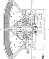
- the contactor represented on the figure 1 is inserted between the terminals 1, 2 of a main circuit supplied with voltages which may be between 0 and 3000 V, preferably between 0 and 1500 V, the dimensions of which make it possible to inscribe the contactor inside a rectangular parallelepiped of about 350 mm in length, by 250 mm in width, and 70 mm in thickness, according to one embodiment of the invention.
- voltages which may be between 0 and 3000 V, preferably between 0 and 1500 V, the dimensions of which make it possible to inscribe the contactor inside a rectangular parallelepiped of about 350 mm in length, by 250 mm in width, and 70 mm in thickness, according to one embodiment of the invention.
- the contactor according to the embodiment of the invention described in detail below is symmetrical with respect to a plane of symmetry passing through the axis AA 'shown in FIG. figure 1 and perpendicular to the cutting plane of the figure 1 .
- the description below may not systematically detail the configuration of the contactor on each side of this plane of symmetry, but the skilled person will understand that everything that is described on one side of this plane is found identically on the other side.
- the contactor comprises an electromechanical breaking member provided with a movable contact support 3 and a fixed contact support 4, 5 on each side of the aforementioned plane of symmetry.
- the movable contact support is a bridge which moves in translation in the direction of the arrow 6 indicated on the figure 1 ; this bridge carries two contact pads 31, 32, which will be called poles 31, 32 in the following description; the poles 31, 32, depending on the position of the movable contact support, establish or interrupt the contact with two corresponding poles 41, 51 situated respectively on the two fixed contact supports.
- Each fixed contact support 4, 5 is electrically connected to a terminal of the main circuit 1, 2 by a first end. At the other end of each fixed contact support, in its extension, is positioned an electric arc guide 7, 8, of conductive material.
- One end of the arc guide 7, 8 is located near but not in electrical contact with the second end of the fixed contact support 4, 5, in the extension of which it is located; the other end of the arc guide joins an extinction zone of the electric arc, which comprises in particular extinction fins 9, 10 of ferromagnetic material.
- the figure 3 illustrates the means that ensures the displacement of the movable contact support 3, to firstly close the main circuit by electrically contacting the corresponding poles of the fixed contact support with those of the movable contact support, on the other hand open the main circuit separating the corresponding poles of the fixed contact support and those of the movable contact support.
- the movable contact support 3 is inserted between two substantially parallel walls of a hollow slider 11 of substantially parallelepiped shape, closed at the top by an upper face transverse to the axis of symmetry of the slider, at the bottom by a lower face transverse to the axis of symmetry of the slider, and at an intermediate level between the top and the bottom, by an intermediate transverse plane 12 to the axis of symmetry of the slider; the movable contact support 3 rests on this intermediate plane 12, on which it is pressed by the pressure of a spring 16 whose first end rests on the movable contact support, and the other end of which rests on the upper face of the slider.
- the slide is secured to a movable ferromagnetic portion 13 fixed to its lower base.
- This moving ferromagnetic part 13 cooperates with an induction coil 14, called an actuating coil 14, powered by a second circuit independent of the main circuit.
- An electronic supply card 33 of the actuating coil provides regulation in voltage and intensity of this power supply.
- This electronic card and the regulation that it provides not only allow to dimension the more precisely the actuator thus significantly reducing the volume and weight of the entire switch, but also to directly deal with the current intensity in this coil to implement a second embodiment of the detector according to the invention which will be described in more detail below.
- the electronic card 33 may also, as is the case in the embodiment shown in the accompanying figures, be split into a portion 33 more particularly dedicated to the supply of the actuating coil, and a portion 33a, gathering especially the components described in more detail below.
- This actuating coil when powered, pulls down the portion 13 and the slider 11 integrally movable until the upper head of this movable portion 13 comes into contact with a fixed second ferromagnetic part, solidary the actuating coil; the lower base of the slide then crushes at least one spring 15 which is supported by its upper end on a portion of the lower base of the slide, and whose lower end is supported on the bottom of the contactor.
- This downward translation of the slider also drives down the movable contact support downwards until the poles of the movable contact support come into contact with their counterparts on each fixed contact support.
- the at least one spring 15 under the lower base of the slider is deployed and pushes the slider upwards, as well as the spring 16 which is deployed simultaneously and adds its own pressure. on the slider, to that exerted by the at least one spring 15, until the movable contact support 3 abuts on the intermediate plane 12 of the slider as shown figure 5 ; during this first part of the upward movement of the slider, the poles of the movable contact support 3 have remained in contact with the poles of the fixed contact supports; under the effect of the at least one spring 15, the slider then continues its upward movement by driving, in this second part of its upward movement, the movable contact support, whose poles then begin to separate only from their homologous poles on the two fixed contact supports.
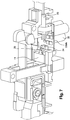
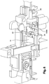
- the detection of the moment of the separation of the fixed and mobile poles is achieved by means of a photoelectric sensor 34 fixed on the power supply card 33bis.
- This sensor 34 is positioned so as to accommodate and cooperate with the end 35 of an integral protrusion of the slide.
- the end 35 is inserted inside a recess adapted to the sensor 34, as illustrated figure 8 , so that the photocell of the sensor 34 detects the presence of the end of the slider.
- the upward movement of the slider causes this end 35 to exit the sensor 34, which the photocell detects immediately.
- the precise moment of the separation of the two fixed and mobile poles is detected thanks to a treatment of the temporal evolution profile of the current in the actuating coil 14 of the slider 11.
- the electronic supply card 33 of the actuating coil 14 which provides voltage regulation and intensity of this power supply makes it possible to directly process the intensity of the current in this coil to implement this second embodiment of the detector according to the invention.
- the figure 6 represents on the abscissa the time, and ordinate U the supply voltage of the actuating coil, and I the intensity of the supply current of the actuating coil.
- the curve 64 in step, represents the evolution of the voltage U as a function of time; at time T1, the voltage U is canceled in the actuating coil.
- Curve 61 represents the evolution of the current flowing through the actuating coil from T1; the intensity begins to decrease, because of the presence of a freewheeling diode across the actuating coil, to reach a first low point at T2.
- This low point marks the moment when the magnetic attraction force of the slide towards the actuating coil 14 becomes smaller than the thrust force exerted on the slide 11 in the opposite direction by the at least one spring 15 and the spring 16.
- T2 thus marks the beginning of the movement of the slider upward, under the effect of the differential between the pressure exerted on the slider upwards by the springs 15 and 16 and the attraction exerted on the slide in the opposite direction by the spool.
- An appropriate electronic circuit is arranged on the electronic control-command card of the actuating coil 14 and makes it possible to process the measurement of the intensity of the current by detecting the moment of appearance T2 from the low point of the intensity curve, and deduce T3. Thus it is possible to optimally synchronize the beginning of the blowing action of the electric arc with the appearance of this electric arc between the fixed and mobile poles.
- a so-called secondary coil 19, 20 is positioned under each fixed contact piece.
- the supply of the secondary coils is independent of that of the main coils. It is provided by a capacitor 38 placed under the card electronic 33bis which controls the supply of the at least one secondary coil 19,20.
- the capacitor 38 may be supplied with power by applying thereto, as well as to the at least one secondary coil 19, 20, a voltage less than, but derived from, that applied to the actuating coil 14. This justifies dedicating to this function a separate part 33bis of the electronic card 33.
- the capacitor 38 is charged by a voltage derived from that which feeds the actuating coil 14 when the latter holds the contactor closed; this charge is made in a very short time, typically less than 1 second, as soon as the contactor closes.
- the discharge of the capacitor 38 which will supply the at least one secondary coil 19,20 is triggered by the component 42, called here trigger, preferably a MOSFET bridge, at the instant which will have been determined as indicated above by the detector 34, after application of an appropriate delay by the component 41 to take into account, if necessary, the shift T3-T2 indicated above.
- the trigger 42 which triggers the discharge of the capacitor also determines the direction of the discharge current as a function of the direction of the current in the contactor as measured by the device 39.
- each secondary coil 19, 20 is associated a pair of flat ferromagnetic plates 21, 22 which face each other on either side of the coil and which are interconnected by a core 36, 37, which is also ferromagnetic and located at inside the coil.
- the figure 1 represents only one of the two ferromagnetic plates of each pair associated with the coil, as well as the core. The second piece faces the first in a plane parallel to the sectional plane of the figure.
- These pairs of plates 21,22 associated with each secondary coil will also be called pairs of secondary plates 21,22.
- This pair of secondary plates 21, 22 is intended, when the secondary coil 19, 20 is energized, to promote the creation of a magnetic field in a direction transverse to the section plane of the figure 1 , between the two parts of this pair of secondary plates.
- This magnetic field is configured to interact with the arc current created between the separated poles to create a force oriented according to the direction of the current and the direction of the magnetic field induced by the secondary coil.
- the direction of the magnetic field induced by the secondary coil is itself a function of the direction of the current flowing through this coil.
- the aim is to blow the arc towards the extinguishing vanes 9, 10 of the arc, in the direction indicated by the arrow 23 on the figure 1 a known electronic device 39 is provided for detecting the direction of the current in the main circuit and for setting accordingly the direction of the current which is discharged from the capacitor 38 to traverse the secondary coil 19 so that the direction of the magnetic field induced by the secondary coil 19 between the two parts of the pair of secondary plates 21 blows the arc current in the direction 23 of the zone of extinction of the bow 9.
- the extension of the zone of influence of the magnetic field produced by a secondary coil stops at the limit of the ferromagnetic part associated with this coil. During its movement towards this limit, the arc lengthens, until it goes out if the intensity of the arc current is weak.
- Sizing the at least one secondary coil and its ferromagnetic core ensures a substantially constant field between the plates for a period of about 30 to 70 ms; this duration is consistent with the extinction time of the arcs for contactors whose circuit is at a constant of high time, greater than 15 ms.
- the zone of extension of the blowing of the secondary coil is configured so that arc currents of low intensity, typically less than 1 or even 2 A, are extinguished under the sole effect of the magnetic blowing due to the secondary coil 19, without that it is necessary to blow them up to the zone of the fins of extinction of the arcs of greater intensity.
- predetermined extinction threshold a certain predetermined threshold, which we will call “predetermined extinction threshold”
- predetermined extinction threshold the arc current will not be extinguished until it has reached, in the direction 23, the the limit of the area of the ferromagnetic plates 21 associated with the coil 19. In this case, before the arc reaches this limit, the arc current has started to feed a main coil 24, 25, which is made in series in the main circuit.
- This main coil is placed above the mobile pole 31, 32 on the movable contact support 3, between this pole 31, 32 and a second arc guide 26, 27 which delimits with the first arc guide 7, 8 the blowing zone towards the extinguishing vanes 9, 10 high intensity arcs; this main coil 24 is in electrical contact at one of these ends with this second arc guide 26 and at the other end with the second main coil 25 of the contactor, so that the main current arriving by one of the pieces of fixed contact 4 jumps to the first arc guide 7 in the extension of this fixed contact piece and, according to the electric arc blown at first by the effect of the secondary coil 19 to the limits of the first plate secondary 21 associated with this secondary coil 19, joins the second arc guide 26 which is connected to the main coil 24 and continues its way to the second main coil 25 of the second part of the symmetrical contactor of the first.
- each coil 24, 25 is associated with a ferromagnetic core and a pair of ferromagnetic plates, said main, 28, 29 to promote the creation of a magnetic field in the same direction as that induced by the secondary coil 19, but in an area that extends the blowing zone of the secondary coil.
- the at least one pair of main plates 28,29 is disposed in the extension of the at least one pair of secondary plates 21,22 associated with the at least one secondary coil, so that the distance between their respective edges is between 2 and 4 mm.
- the at least one main coil 24,25 and their ferromagnetic core is sized to ensure, when it is traversed by a current of intensity at least equal to the "predetermined threshold of extinction" mentioned above, a field magnetic between the plates of the at least one pair of plates 28, 29 of sufficient intensity to continue the elongation of the arc beyond the limit of the zone of influence of the at least one secondary coil 19,20 corresponding.
- predetermined extinction threshold which characterizes the intensity of the arc current below which the arc elongates and extinguishes under the effect of the single secondary coil before reaching the zone of influence of the main coil, varies in the opposite direction of the voltage across the contactor: the higher the voltage, the lower the intensity corresponding to this "predetermined threshold of extinction”.
- the "predetermined threshold of extinction” chosen for the dimensioning of the at least one secondary and main coil is that corresponding to the highest voltage allowed across the contactor.
Landscapes
- Physics & Mathematics (AREA)
- Electromagnetism (AREA)
- Arc-Extinguishing Devices That Are Switches (AREA)
Priority Applications (1)
| Application Number | Priority Date | Filing Date | Title |
|---|---|---|---|
| EP17151114.0A EP3349231B1 (de) | 2017-01-12 | 2017-01-12 | Elektromechanisches schütz |
Applications Claiming Priority (1)
| Application Number | Priority Date | Filing Date | Title |
|---|---|---|---|
| EP17151114.0A EP3349231B1 (de) | 2017-01-12 | 2017-01-12 | Elektromechanisches schütz |
Publications (2)
| Publication Number | Publication Date |
|---|---|
| EP3349231A1 true EP3349231A1 (de) | 2018-07-18 |
| EP3349231B1 EP3349231B1 (de) | 2023-07-19 |
Family
ID=57794166
Family Applications (1)
| Application Number | Title | Priority Date | Filing Date |
|---|---|---|---|
| EP17151114.0A Active EP3349231B1 (de) | 2017-01-12 | 2017-01-12 | Elektromechanisches schütz |
Country Status (1)
| Country | Link |
|---|---|
| EP (1) | EP3349231B1 (de) |
Cited By (1)
| Publication number | Priority date | Publication date | Assignee | Title |
|---|---|---|---|---|
| WO2020035489A1 (en) * | 2018-08-15 | 2020-02-20 | Eaton Intelligent Power Limited | Switching device and method for operating a switching device |
Citations (5)
| Publication number | Priority date | Publication date | Assignee | Title |
|---|---|---|---|---|
| FR640912A (fr) * | 1926-07-12 | 1928-07-24 | Thomson Houston Comp Francaise | Perfectionnements aux contacteurs, aux interrupteurs, et aux disjoncteurs à soufflage magnétique |
| FR1342851A (fr) * | 1962-09-19 | 1963-11-15 | Cem Comp Electro Mec | Pôle à double coupure pour contacteurs électromagnétiques ou pneumatiques montés sur barreaux |
| US5138122A (en) * | 1990-08-29 | 1992-08-11 | Eaton Corporation | Bi-directional direct current switching apparatus having arc extinguishing chambers alternatively used according to polarity applied to said apparatus |
| DE20105432U1 (de) * | 2001-03-28 | 2002-09-26 | Schaltbau GmbH, 81677 München | Blasung bei AC-Betrieb |
| EP2230678A2 (de) * | 2009-03-16 | 2010-09-22 | Schaltbau GmbH | Lichtbogenresistenter Schütz |
Family Cites Families (1)
| Publication number | Priority date | Publication date | Assignee | Title |
|---|---|---|---|---|
| DE102006035844B4 (de) * | 2006-08-01 | 2008-06-19 | Schaltbau Gmbh | Schütz für Gleichstrom- und Wechselstrombetrieb |
-
2017
- 2017-01-12 EP EP17151114.0A patent/EP3349231B1/de active Active
Patent Citations (5)
| Publication number | Priority date | Publication date | Assignee | Title |
|---|---|---|---|---|
| FR640912A (fr) * | 1926-07-12 | 1928-07-24 | Thomson Houston Comp Francaise | Perfectionnements aux contacteurs, aux interrupteurs, et aux disjoncteurs à soufflage magnétique |
| FR1342851A (fr) * | 1962-09-19 | 1963-11-15 | Cem Comp Electro Mec | Pôle à double coupure pour contacteurs électromagnétiques ou pneumatiques montés sur barreaux |
| US5138122A (en) * | 1990-08-29 | 1992-08-11 | Eaton Corporation | Bi-directional direct current switching apparatus having arc extinguishing chambers alternatively used according to polarity applied to said apparatus |
| DE20105432U1 (de) * | 2001-03-28 | 2002-09-26 | Schaltbau GmbH, 81677 München | Blasung bei AC-Betrieb |
| EP2230678A2 (de) * | 2009-03-16 | 2010-09-22 | Schaltbau GmbH | Lichtbogenresistenter Schütz |
Cited By (3)
| Publication number | Priority date | Publication date | Assignee | Title |
|---|---|---|---|---|
| WO2020035489A1 (en) * | 2018-08-15 | 2020-02-20 | Eaton Intelligent Power Limited | Switching device and method for operating a switching device |
| US11521817B2 (en) | 2018-08-15 | 2022-12-06 | Eaton Intelligent Power Limited | Switching device and method for operating a switching device |
| EP4589620A3 (de) * | 2018-08-15 | 2025-10-15 | Eaton Intelligent Power Limited | Schaltvorrichtung und verfahren zum betrieb der schaltvorrichtung |
Also Published As
| Publication number | Publication date |
|---|---|
| EP3349231B1 (de) | 2023-07-19 |
Similar Documents
| Publication | Publication Date | Title |
|---|---|---|
| CA1182156A (fr) | Contacteur muni de moyens d'auto-protection contre les effets des forces de repulsion entre les contacts, et son association a un organe de coupure et de limitation des courants de court-circuit | |
| EP0326449A1 (de) | Elektromagnetischer Auslöser mit einstellbarem Ansprechwert | |
| EP0486389A1 (de) | Schutzschalter | |
| EP3014645B1 (de) | Elektrisches schütz und verfahren zur steuerung solch eines schützes | |
| FR3027728A1 (fr) | Dispositif de coupure d'arc electrique | |
| EP0013642B1 (de) | Strombegrenzender Selbstschalter für Niederspannung | |
| EP3349231B1 (de) | Elektromechanisches schütz | |
| EP3349232B1 (de) | Elektromechanischer schutz | |
| FR2595863A1 (fr) | Interrupteur de circuit a haute vitesse a limitation du courant | |
| EP2333805A1 (de) | Ferngesteuerte Unterbrechungsvorrichtung, und mit dieser Unterbrechungsvorrichtung ausgestattete Stromverteilungsvorrichtung | |
| EP0537090B1 (de) | Elektrischer Schützschalter mit Einfügung von zusätzlichen Windungen im Magnetauslöser | |
| FR2676587A1 (fr) | Disjoncteur a grand pouvoir de coupure. | |
| FR2595865A1 (fr) | Interrupteur electrique, plus particulierement son actionneur magnetique de contact a haute vitesse | |
| CH699821B1 (fr) | Coupe-circuit électromécanique et procédé pour couper le courant dans ce coupe-circuit électromécanique. | |
| EP3699942B1 (de) | Einschaltsystem einer vakuumschaltröhre | |
| FR2595866A1 (fr) | Dispositif d'entrainement de contact a haute vitesse pour interrupteur de circuit | |
| FR2958447A1 (fr) | Declencheur electromagnetique pour appareil electrique interrupteur, appareil electrique interrupteur comportant un tel declencheur | |
| EP0866483B1 (de) | Bistabiler Batterieschalter mit mechanischer Verriegelung | |
| EP0905735B1 (de) | Schutzschalter mit elektromagnetischen Auslöser mit Antrieb für einen beweglichen und gabelförmigen Kontakt | |
| EP1134767A1 (de) | Magnetisch wirkende Auslösevorrichtung für einen Schutzschalter, und elektrischer Schutzapparat ausgerüstet mit einer solchen Vorrichtung | |
| EP3109879A1 (de) | Lichtbogenlöschvorrichtung in einem elektrischen schutzgerät, und elektrisches schutzgerät, das eine solche vorrichtung umfasst | |
| FR2641643A1 (fr) | Disjoncteur a haute ou moyenne tension | |
| FR2953979A1 (fr) | Dispositif de coupure avec circuit magnetique de renforcement | |
| FR2534080A1 (fr) | Appareil de mise a la masse automatique de structures accidentellement sous tension | |
| EP0054499A1 (de) | Schalter mit Trennung des Nulleiters |
Legal Events
| Date | Code | Title | Description |
|---|---|---|---|
| PUAI | Public reference made under article 153(3) epc to a published international application that has entered the european phase |
Free format text: ORIGINAL CODE: 0009012 |
|
| STAA | Information on the status of an ep patent application or granted ep patent |
Free format text: STATUS: THE APPLICATION HAS BEEN PUBLISHED |
|
| AK | Designated contracting states |
Kind code of ref document: A1 Designated state(s): AL AT BE BG CH CY CZ DE DK EE ES FI FR GB GR HR HU IE IS IT LI LT LU LV MC MK MT NL NO PL PT RO RS SE SI SK SM TR |
|
| AX | Request for extension of the european patent |
Extension state: BA ME |
|
| STAA | Information on the status of an ep patent application or granted ep patent |
Free format text: STATUS: REQUEST FOR EXAMINATION WAS MADE |
|
| 17P | Request for examination filed |
Effective date: 20190115 |
|
| RBV | Designated contracting states (corrected) |
Designated state(s): AL AT BE BG CH CY CZ DE DK EE ES FI FR GB GR HR HU IE IS IT LI LT LU LV MC MK MT NL NO PL PT RO RS SE SI SK SM TR |
|
| STAA | Information on the status of an ep patent application or granted ep patent |
Free format text: STATUS: EXAMINATION IS IN PROGRESS |
|
| 17Q | First examination report despatched |
Effective date: 20210129 |
|
| GRAP | Despatch of communication of intention to grant a patent |
Free format text: ORIGINAL CODE: EPIDOSNIGR1 |
|
| STAA | Information on the status of an ep patent application or granted ep patent |
Free format text: STATUS: GRANT OF PATENT IS INTENDED |
|
| INTG | Intention to grant announced |
Effective date: 20230214 |
|
| GRAS | Grant fee paid |
Free format text: ORIGINAL CODE: EPIDOSNIGR3 |
|
| GRAA | (expected) grant |
Free format text: ORIGINAL CODE: 0009210 |
|
| STAA | Information on the status of an ep patent application or granted ep patent |
Free format text: STATUS: THE PATENT HAS BEEN GRANTED |
|
| AK | Designated contracting states |
Kind code of ref document: B1 Designated state(s): AL AT BE BG CH CY CZ DE DK EE ES FI FR GB GR HR HU IE IS IT LI LT LU LV MC MK MT NL NO PL PT RO RS SE SI SK SM TR |
|
| REG | Reference to a national code |
Ref country code: GB Ref legal event code: FG4D Free format text: NOT ENGLISH |
|
| REG | Reference to a national code |
Ref country code: CH Ref legal event code: EP |
|
| REG | Reference to a national code |
Ref country code: DE Ref legal event code: R096 Ref document number: 602017071400 Country of ref document: DE |
|
| REG | Reference to a national code |
Ref country code: IE Ref legal event code: FG4D Free format text: LANGUAGE OF EP DOCUMENT: FRENCH |
|
| REG | Reference to a national code |
Ref country code: LT Ref legal event code: MG9D |
|
| REG | Reference to a national code |
Ref country code: NL Ref legal event code: MP Effective date: 20230719 |
|
| REG | Reference to a national code |
Ref country code: AT Ref legal event code: MK05 Ref document number: 1590345 Country of ref document: AT Kind code of ref document: T Effective date: 20230719 |
|
| PG25 | Lapsed in a contracting state [announced via postgrant information from national office to epo] |
Ref country code: NL Free format text: LAPSE BECAUSE OF FAILURE TO SUBMIT A TRANSLATION OF THE DESCRIPTION OR TO PAY THE FEE WITHIN THE PRESCRIBED TIME-LIMIT Effective date: 20230719 |
|
| PG25 | Lapsed in a contracting state [announced via postgrant information from national office to epo] |
Ref country code: GR Free format text: LAPSE BECAUSE OF FAILURE TO SUBMIT A TRANSLATION OF THE DESCRIPTION OR TO PAY THE FEE WITHIN THE PRESCRIBED TIME-LIMIT Effective date: 20231020 |
|
| PG25 | Lapsed in a contracting state [announced via postgrant information from national office to epo] |
Ref country code: IS Free format text: LAPSE BECAUSE OF FAILURE TO SUBMIT A TRANSLATION OF THE DESCRIPTION OR TO PAY THE FEE WITHIN THE PRESCRIBED TIME-LIMIT Effective date: 20231119 |
|
| PG25 | Lapsed in a contracting state [announced via postgrant information from national office to epo] |
Ref country code: SE Free format text: LAPSE BECAUSE OF FAILURE TO SUBMIT A TRANSLATION OF THE DESCRIPTION OR TO PAY THE FEE WITHIN THE PRESCRIBED TIME-LIMIT Effective date: 20230719 Ref country code: RS Free format text: LAPSE BECAUSE OF FAILURE TO SUBMIT A TRANSLATION OF THE DESCRIPTION OR TO PAY THE FEE WITHIN THE PRESCRIBED TIME-LIMIT Effective date: 20230719 Ref country code: PT Free format text: LAPSE BECAUSE OF FAILURE TO SUBMIT A TRANSLATION OF THE DESCRIPTION OR TO PAY THE FEE WITHIN THE PRESCRIBED TIME-LIMIT Effective date: 20231120 Ref country code: NO Free format text: LAPSE BECAUSE OF FAILURE TO SUBMIT A TRANSLATION OF THE DESCRIPTION OR TO PAY THE FEE WITHIN THE PRESCRIBED TIME-LIMIT Effective date: 20231019 Ref country code: LV Free format text: LAPSE BECAUSE OF FAILURE TO SUBMIT A TRANSLATION OF THE DESCRIPTION OR TO PAY THE FEE WITHIN THE PRESCRIBED TIME-LIMIT Effective date: 20230719 Ref country code: LT Free format text: LAPSE BECAUSE OF FAILURE TO SUBMIT A TRANSLATION OF THE DESCRIPTION OR TO PAY THE FEE WITHIN THE PRESCRIBED TIME-LIMIT Effective date: 20230719 Ref country code: IS Free format text: LAPSE BECAUSE OF FAILURE TO SUBMIT A TRANSLATION OF THE DESCRIPTION OR TO PAY THE FEE WITHIN THE PRESCRIBED TIME-LIMIT Effective date: 20231119 Ref country code: HR Free format text: LAPSE BECAUSE OF FAILURE TO SUBMIT A TRANSLATION OF THE DESCRIPTION OR TO PAY THE FEE WITHIN THE PRESCRIBED TIME-LIMIT Effective date: 20230719 Ref country code: GR Free format text: LAPSE BECAUSE OF FAILURE TO SUBMIT A TRANSLATION OF THE DESCRIPTION OR TO PAY THE FEE WITHIN THE PRESCRIBED TIME-LIMIT Effective date: 20231020 Ref country code: FI Free format text: LAPSE BECAUSE OF FAILURE TO SUBMIT A TRANSLATION OF THE DESCRIPTION OR TO PAY THE FEE WITHIN THE PRESCRIBED TIME-LIMIT Effective date: 20230719 Ref country code: AT Free format text: LAPSE BECAUSE OF FAILURE TO SUBMIT A TRANSLATION OF THE DESCRIPTION OR TO PAY THE FEE WITHIN THE PRESCRIBED TIME-LIMIT Effective date: 20230719 |
|
| PG25 | Lapsed in a contracting state [announced via postgrant information from national office to epo] |
Ref country code: PL Free format text: LAPSE BECAUSE OF FAILURE TO SUBMIT A TRANSLATION OF THE DESCRIPTION OR TO PAY THE FEE WITHIN THE PRESCRIBED TIME-LIMIT Effective date: 20230719 |
|
| REG | Reference to a national code |
Ref country code: DE Ref legal event code: R097 Ref document number: 602017071400 Country of ref document: DE |
|
| PG25 | Lapsed in a contracting state [announced via postgrant information from national office to epo] |
Ref country code: ES Free format text: LAPSE BECAUSE OF FAILURE TO SUBMIT A TRANSLATION OF THE DESCRIPTION OR TO PAY THE FEE WITHIN THE PRESCRIBED TIME-LIMIT Effective date: 20230719 |
|
| PG25 | Lapsed in a contracting state [announced via postgrant information from national office to epo] |
Ref country code: SM Free format text: LAPSE BECAUSE OF FAILURE TO SUBMIT A TRANSLATION OF THE DESCRIPTION OR TO PAY THE FEE WITHIN THE PRESCRIBED TIME-LIMIT Effective date: 20230719 Ref country code: RO Free format text: LAPSE BECAUSE OF FAILURE TO SUBMIT A TRANSLATION OF THE DESCRIPTION OR TO PAY THE FEE WITHIN THE PRESCRIBED TIME-LIMIT Effective date: 20230719 Ref country code: ES Free format text: LAPSE BECAUSE OF FAILURE TO SUBMIT A TRANSLATION OF THE DESCRIPTION OR TO PAY THE FEE WITHIN THE PRESCRIBED TIME-LIMIT Effective date: 20230719 Ref country code: EE Free format text: LAPSE BECAUSE OF FAILURE TO SUBMIT A TRANSLATION OF THE DESCRIPTION OR TO PAY THE FEE WITHIN THE PRESCRIBED TIME-LIMIT Effective date: 20230719 Ref country code: DK Free format text: LAPSE BECAUSE OF FAILURE TO SUBMIT A TRANSLATION OF THE DESCRIPTION OR TO PAY THE FEE WITHIN THE PRESCRIBED TIME-LIMIT Effective date: 20230719 Ref country code: CZ Free format text: LAPSE BECAUSE OF FAILURE TO SUBMIT A TRANSLATION OF THE DESCRIPTION OR TO PAY THE FEE WITHIN THE PRESCRIBED TIME-LIMIT Effective date: 20230719 Ref country code: SK Free format text: LAPSE BECAUSE OF FAILURE TO SUBMIT A TRANSLATION OF THE DESCRIPTION OR TO PAY THE FEE WITHIN THE PRESCRIBED TIME-LIMIT Effective date: 20230719 |
|
| PLBE | No opposition filed within time limit |
Free format text: ORIGINAL CODE: 0009261 |
|
| STAA | Information on the status of an ep patent application or granted ep patent |
Free format text: STATUS: NO OPPOSITION FILED WITHIN TIME LIMIT |
|
| PG25 | Lapsed in a contracting state [announced via postgrant information from national office to epo] |
Ref country code: IT Free format text: LAPSE BECAUSE OF FAILURE TO SUBMIT A TRANSLATION OF THE DESCRIPTION OR TO PAY THE FEE WITHIN THE PRESCRIBED TIME-LIMIT Effective date: 20230719 |
|
| 26N | No opposition filed |
Effective date: 20240422 |
|
| PG25 | Lapsed in a contracting state [announced via postgrant information from national office to epo] |
Ref country code: SI Free format text: LAPSE BECAUSE OF FAILURE TO SUBMIT A TRANSLATION OF THE DESCRIPTION OR TO PAY THE FEE WITHIN THE PRESCRIBED TIME-LIMIT Effective date: 20230719 |
|
| PG25 | Lapsed in a contracting state [announced via postgrant information from national office to epo] |
Ref country code: MC Free format text: LAPSE BECAUSE OF FAILURE TO SUBMIT A TRANSLATION OF THE DESCRIPTION OR TO PAY THE FEE WITHIN THE PRESCRIBED TIME-LIMIT Effective date: 20230719 |
|
| PG25 | Lapsed in a contracting state [announced via postgrant information from national office to epo] |
Ref country code: MC Free format text: LAPSE BECAUSE OF FAILURE TO SUBMIT A TRANSLATION OF THE DESCRIPTION OR TO PAY THE FEE WITHIN THE PRESCRIBED TIME-LIMIT Effective date: 20230719 |
|
| REG | Reference to a national code |
Ref country code: CH Ref legal event code: PL |
|
| PG25 | Lapsed in a contracting state [announced via postgrant information from national office to epo] |
Ref country code: LU Free format text: LAPSE BECAUSE OF NON-PAYMENT OF DUE FEES Effective date: 20240112 |
|
| GBPC | Gb: european patent ceased through non-payment of renewal fee |
Effective date: 20240112 |
|
| PG25 | Lapsed in a contracting state [announced via postgrant information from national office to epo] |
Ref country code: LU Free format text: LAPSE BECAUSE OF NON-PAYMENT OF DUE FEES Effective date: 20240112 |
|
| PG25 | Lapsed in a contracting state [announced via postgrant information from national office to epo] |
Ref country code: GB Free format text: LAPSE BECAUSE OF NON-PAYMENT OF DUE FEES Effective date: 20240112 |
|
| PG25 | Lapsed in a contracting state [announced via postgrant information from national office to epo] |
Ref country code: BE Free format text: LAPSE BECAUSE OF NON-PAYMENT OF DUE FEES Effective date: 20240131 |
|
| PG25 | Lapsed in a contracting state [announced via postgrant information from national office to epo] |
Ref country code: CH Free format text: LAPSE BECAUSE OF NON-PAYMENT OF DUE FEES Effective date: 20240131 |
|
| PG25 | Lapsed in a contracting state [announced via postgrant information from national office to epo] |
Ref country code: GB Free format text: LAPSE BECAUSE OF NON-PAYMENT OF DUE FEES Effective date: 20240112 Ref country code: CH Free format text: LAPSE BECAUSE OF NON-PAYMENT OF DUE FEES Effective date: 20240131 Ref country code: BE Free format text: LAPSE BECAUSE OF NON-PAYMENT OF DUE FEES Effective date: 20240131 |
|
| REG | Reference to a national code |
Ref country code: BE Ref legal event code: MM Effective date: 20240131 |
|
| PG25 | Lapsed in a contracting state [announced via postgrant information from national office to epo] |
Ref country code: BG Free format text: LAPSE BECAUSE OF FAILURE TO SUBMIT A TRANSLATION OF THE DESCRIPTION OR TO PAY THE FEE WITHIN THE PRESCRIBED TIME-LIMIT Effective date: 20230719 |
|
| PG25 | Lapsed in a contracting state [announced via postgrant information from national office to epo] |
Ref country code: BG Free format text: LAPSE BECAUSE OF FAILURE TO SUBMIT A TRANSLATION OF THE DESCRIPTION OR TO PAY THE FEE WITHIN THE PRESCRIBED TIME-LIMIT Effective date: 20230719 |
|
| PG25 | Lapsed in a contracting state [announced via postgrant information from national office to epo] |
Ref country code: IE Free format text: LAPSE BECAUSE OF NON-PAYMENT OF DUE FEES Effective date: 20240112 |
|
| PG25 | Lapsed in a contracting state [announced via postgrant information from national office to epo] |
Ref country code: IE Free format text: LAPSE BECAUSE OF NON-PAYMENT OF DUE FEES Effective date: 20240112 |
|
| PG25 | Lapsed in a contracting state [announced via postgrant information from national office to epo] |
Ref country code: CY Free format text: LAPSE BECAUSE OF FAILURE TO SUBMIT A TRANSLATION OF THE DESCRIPTION OR TO PAY THE FEE WITHIN THE PRESCRIBED TIME-LIMIT; INVALID AB INITIO Effective date: 20170112 |
|
| PG25 | Lapsed in a contracting state [announced via postgrant information from national office to epo] |
Ref country code: HU Free format text: LAPSE BECAUSE OF FAILURE TO SUBMIT A TRANSLATION OF THE DESCRIPTION OR TO PAY THE FEE WITHIN THE PRESCRIBED TIME-LIMIT; INVALID AB INITIO Effective date: 20170112 |
|
| PG25 | Lapsed in a contracting state [announced via postgrant information from national office to epo] |
Ref country code: TR Free format text: LAPSE BECAUSE OF FAILURE TO SUBMIT A TRANSLATION OF THE DESCRIPTION OR TO PAY THE FEE WITHIN THE PRESCRIBED TIME-LIMIT Effective date: 20230719 |
|
| PGFP | Annual fee paid to national office [announced via postgrant information from national office to epo] |
Ref country code: DE Payment date: 20260121 Year of fee payment: 10 |
|
| PGFP | Annual fee paid to national office [announced via postgrant information from national office to epo] |
Ref country code: FR Payment date: 20260123 Year of fee payment: 10 |