EP3349232B1 - Elektromechanischer schutz - Google Patents
Elektromechanischer schutz Download PDFInfo
- Publication number
- EP3349232B1 EP3349232B1 EP17151115.7A EP17151115A EP3349232B1 EP 3349232 B1 EP3349232 B1 EP 3349232B1 EP 17151115 A EP17151115 A EP 17151115A EP 3349232 B1 EP3349232 B1 EP 3349232B1
- Authority
- EP
- European Patent Office
- Prior art keywords
- coil
- instant
- pole
- actuating
- movable
- Prior art date
- Legal status (The legal status is an assumption and is not a legal conclusion. Google has not performed a legal analysis and makes no representation as to the accuracy of the status listed.)
- Active
Links
Images


Classifications
-
- H—ELECTRICITY
- H01—ELECTRIC ELEMENTS
- H01H—ELECTRIC SWITCHES; RELAYS; SELECTORS; EMERGENCY PROTECTIVE DEVICES
- H01H9/00—Details of switching devices, not covered by groups H01H1/00 - H01H7/00
- H01H9/30—Means for extinguishing or preventing arc between current-carrying parts
- H01H9/44—Means for extinguishing or preventing arc between current-carrying parts using blow-out magnet
-
- H—ELECTRICITY
- H01—ELECTRIC ELEMENTS
- H01H—ELECTRIC SWITCHES; RELAYS; SELECTORS; EMERGENCY PROTECTIVE DEVICES
- H01H9/00—Details of switching devices, not covered by groups H01H1/00 - H01H7/00
- H01H9/50—Means for detecting the presence of an arc or discharge
-
- H—ELECTRICITY
- H01—ELECTRIC ELEMENTS
- H01H—ELECTRIC SWITCHES; RELAYS; SELECTORS; EMERGENCY PROTECTIVE DEVICES
- H01H9/00—Details of switching devices, not covered by groups H01H1/00 - H01H7/00
- H01H9/54—Circuit arrangements not adapted to a particular application of the switching device and for which no provision exists elsewhere
Definitions
- the present invention relates to the field of electromechanical contactors, suitable in particular, but not exclusively, for the protection of high voltage electrical installations such as, for example, those used in rail transport networks.
- Known electromechanical contactors usually include at least one fixed pole and at least one movable pole. These poles are in contact to let the current pass and are separated to interrupt it.
- An electromechanical actuator is usually used to move the movable contact so as to separate it from the fixed contact. An electric arc is created between the two contacts, which must be extinguished as effectively as possible.
- the known means for extinguishing this electric arc comprise devices for electromagnetically blowing the arc towards means configured to separate and disperse the arc into a multitude of arcs which eventually extinguish.
- Electromagnetic blowing results from the effect of the Lorentz force produced by a magnetic field on the electric arc, the magnetic field being able to be created by a permanent magnet or by a coil crossed by a current of intensity adapted to the effect. research.
- the effectiveness of these electromagnetic blowing devices depends very much on the quality of the synchronization between the start of contact separation, and therefore the appearance of the electric arc, and the start of the blowing effect.
- the document EP 2,230,678 B1 discloses an electromechanical contactor according to the preamble of claim 1.
- the first arc blowing means of the electromechanical contactor of said document can be a coil supplied permanently.
- the present invention aims to solve all or part of the drawbacks mentioned above, by making the triggering of the electromagnetic blowing depend on the precise moment when the movable and fixed contacts begin to separate.
- the present invention relates to an electromechanical contactor according to claim 1.
- the blowing is started substantially simultaneously at the instant of separation between the at least one fixed pole and the at least one movable pole.
- the trigger is configured to trigger a magnetic field with the discharge of a capacitor in the at least one coil.
- the direction of the discharge current of the capacitor in the at least one coil is determined by a device for detecting the direction of the current in the electromechanical contactor.
- the electric arc will be blown by the magnetic field of the at least one coil always in the same direction, regardless of the direction of the current in the electromechanical contactor.
- the detector is a position sensor of the actuation means of the at least one movable pole.
- the position sensor is a photoelectric sensor, in particular a transmissive photo-switch, configured to cooperate with the mobile part of the actuating means so as to determine the instant of separation of the at least one mobile pole and at least one fixed pole.
- the detector is a signal processing means configured to detect the instant when the intensity in the actuating coil reaches a minimum value after the cancellation of the voltage across the terminals of the coil d actuation.
- the separation instant is determined by applying a predetermined delay to the instant when the intensity in the actuating coil reaches a minimum value after the cancellation of the voltage across the terminals of the coil. actuation.
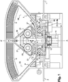
- the contactor shown in the figure 1 is inserted between terminals 1, 2 of a main circuit supplied with voltages which can be between 0 and 3000 V, preferably between 0 and 1500 V, the dimensions of which allow the contactor to be inserted inside a rectangular parallelepiped of about 350 mm in length, 250 mm in width, and 70 mm in thickness, according to an embodiment of the invention.
- the contactor according to the embodiment of the invention described in detail below is symmetrical with respect to a plane of symmetry passing through the axis AA 'shown in the figure 1 and perpendicular to the section plane of the figure 1 .
- the description below may not systematically detail the configuration of the contactor on each side of this plane of symmetry, but those skilled in the art will understand that everything that is described on one side of this plane is found identically on the other. side.
- the contactor comprises an electromechanical breaking member provided with a movable contact support 3 and with a fixed contact support 4, 5 on each side of the above-mentioned plane of symmetry.
- the mobile contact support is a bridge which moves in translation in the direction of arrow 6 indicated on the figure 1 ; this bridge carries two contact pads 31, 32, which will be called poles 31, 32 in the following description; the poles 31, 32, depending on the position of the mobile contact support, establish or interrupt contact with two corresponding poles 41, 51 located respectively on the two fixed contact supports.
- Each fixed contact support 4, 5 is electrically connected to a terminal of the main circuit 1, 2 by a first end.
- an electric arc guide 7, 8 made of conductive material.
- One end of the arc guide 7, 8 is located near but not in electrical contact with the second end of the fixed contact support 4, 5, in the extension of which it is located; the other end of the arc guide joins an extinction zone of the electric arc, which in particular comprises extinction fins 9, 10 made of ferromagnetic material.
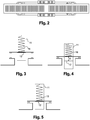
- the figure 3 illustrates the means which ensures the displacement of the mobile contact support 3, in order to close the main circuit on the one hand by putting in electrical contact the corresponding poles of the fixed contact support with those of the mobile contact support, on the other hand open main circuit separating the corresponding poles of the fixed contact support and those of the mobile contact support.
- the movable contact support 3 is inserted between two substantially parallel walls of a hollow slide 11 of substantially parallelepiped shape, closed at the top by an upper face transverse to the axis of symmetry of the slide, at the bottom by a lower face transverse to the 'axis of symmetry of the slide, and at an intermediate level between the top and the bottom, by an intermediate plane transverse to the axis of symmetry of the slide; the mobile contact support 3 rests on this intermediate plane 12, on which it is pressed by the pressure of a spring 16, one end of which rests on the mobile contact support, and the other end of which rests on the upper face of the slide.
- the slide is secured to a movable ferromagnetic part 13 fixed to its lower base.
- This movable ferromagnetic part 13 cooperates with an induction coil 14, called the actuation coil 14, supplied by a second circuit independent of the main circuit.
- An electronic power supply card 33 for the actuating coil provides voltage and intensity regulation for this supply.
- This electronic card and the regulation it provides not only allow the actuator to be dimensioned as accurately as possible, thereby considerably reducing the volume and weight of the entire contactor, but also to directly treat the intensity of the current in this coil to implement a second embodiment of the detector according to the invention which will be described in more detail below.
- the electronic card 33 can also, as is the case in the embodiment shown in the appended figures, be divided into a part 33 more particularly dedicated to supplying the actuating coil, and a part 33a, bringing together especially the components described in more detail below.
- This actuating coil when it is supplied, draws down the part 13 and the slide 11 which are integrally movable until the upper head of this movable part 13 comes into contact with a second fixed ferromagnetic part, which is integral the actuating coil; the lower base of the slide then crushes at least one spring 15 which is supported by its upper end on a part of the lower base of the slide, and whose lower end is in contact with the bottom of the contactor.
- This downward translation of the slide also drives the mobile contact support downward until the poles of the mobile contact support come into contact with their counterparts on each fixed contact support.
- the at least one spring 15 under the lower base of the slider deploys and pushes the slider upwards, as well as the spring 16 which deploys simultaneously and adds its own pressure on the slide, to that exerted by the at least one spring 15, until the movable contact support 3 abuts on the intermediate plane 12 of the slide as indicated figure 5 ; during this first part of the upward movement of the slide, the poles of the mobile contact support 3 have remained in contact with the poles of the fixed contact supports; under the effect of at least one spring 15, the slide then continues its upward movement, causing, in this second part of its upward movement, the support of mobile contact, the poles of which then only begin to separate from their homologous poles on the two fixed contact supports.
- the detection of the moment of separation of the fixed and mobile poles is carried out by means of a photoelectric sensor 34 fixed on the power supply board 33bis.
- This sensor 34 is positioned so as to be able to receive and cooperate with the end 35 of a protuberance integral with the slide.
- the end 35 is inserted inside a suitable recess of the sensor 34, as illustrated figure 8 , so that the photoelectric cell of the sensor 34 detects the presence of the end of the slider.
- the movement of the slide upwards, as described above, has the effect of bringing this end 35 out of the sensor 34, which the photoelectric cell detects immediately.
- the precise moment of the separation of the two fixed and mobile poles is detected by processing the profile of the time course of the current in the actuating coil 14 of the slide 11.
- the electronic power supply card 33 of the actuating coil 14 which regulates the voltage and intensity of this supply makes it possible to directly treat the intensity of the current in this coil to implement this second embodiment of the detector according to the invention.
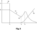
- the figure 6 represents on the abscissa the time, and ordered U the supply voltage of the actuating coil, and I the intensity of the supply current of the actuating coil.
- Curve 64, on the staircase represents the evolution of the voltage U as a function of time; at time T1, the voltage U is canceled in the actuating coil.
- Curve 61 represents the evolution of the current flowing through the actuating coil from T1; the intensity begins to decrease, due to the presence of a freewheeling diode across the actuating coil, to reach a first low point at T2. This low point marks the moment when the magnetic attraction force of the slider towards the actuating coil 14 becomes less than the pushing force exerted on the slider 11 in the opposite direction by the at least one spring 15 and the spring 16.
- T2 therefore marks the beginning of the movement of the ram upwards, under the effect of the differential between the pressure exerted on the ram upwards by the springs 15 and 16 and the attraction exerted on the ram in opposite directions by the coil d 'actuation 14; this movement moves the slide from the position shown on the figure 4 at the position shown on the figure 5 , which it reaches at time T3, then at the position represented on the figure 3 . It is at instant T3 that the blowing of the secondary coil 19, 20 should be triggered. This instant T3 is offset by T2 by a constant delay related to the time of movement of the slide between the position shown in the figure 4 up to that shown in figure 5 ; this constant T3-T2 is determined empirically by calibration tests of the device.
- An appropriate electronic circuit is placed on the electronic control-command card of the actuating coil 14 and makes it possible to process the measurement of the current intensity by detecting the instant of appearance T2 from the low point of the intensity curve, and deduce T3 from it. Thus it is possible to synchronize optimally the start of the blowing action of the electric arc with the appearance of this electric arc between the fixed and mobile poles.
- a so-called secondary coil 19, 20 is positioned under each fixed contact part.
- the supply of the secondary coils is independent of that of the main coils. It is provided by a capacitor 38 placed under the electronic card 33bis which controls the supply of the at least one secondary coil 19,20.
- the capacitor 38 can be supplied with power by applying to the latter, as well as to the at least one secondary coil 19, 20, a voltage lower than that which is applied to the actuating coil 14. This justifies to dedicate to this function a separate part 33bis of the electronic card 33.
- the capacitor 38 is charged by a voltage derived from that which supplies the actuating coil 14 when the latter keeps the contactor closed; this charge is carried out in a very short time, typically less than 1 second, as soon as the contactor closes.
- the discharge of the capacitor 38 which will supply the at least one secondary coil 19, 20 is triggered by the component 42, here called the trigger, preferably a MOSFET bridge, at the instant which will have been determined as indicated above by the detector 34, after application of an appropriate delay by the component 41 to take account, if necessary, of the offset T3-T2 indicated above.
- the trigger 42 which initiates the discharge of the capacitor also determines the direction of the discharge current as a function of the direction of the current in the contactor as measured by the device 39.
- Each secondary coil 19, 20 is associated with a pair of planar ferromagnetic plates 21, 22 which face each other on both sides of the coil and which are connected together by a core 36, 37, also ferromagnetic and located at the inside the coil.
- the figure 1 represents only one of the two ferromagnetic plates of each pair associated with the coil, as well as the core. The second part faces the first in a plane parallel to the section plane of the figure.
- These pairs of plates 21, 22, associated with each secondary coil will also be called pairs of secondary plates 21, 22.
- This pair of secondary plates 21, 22 is intended, when the secondary coil 19, 20 is energized, to promote the creation of a magnetic field in a direction transverse to the cutting plane of the figure 1 , between the two parts of this pair of secondary plates.
- This magnetic field is configured to interact with the arc current created between the separate poles to create an oriented force as a function of the direction of the current and the direction of the magnetic field induced by the secondary coil.
- the direction of the magnetic field induced by the secondary coil is itself a function of the direction of the current flowing through this coil.
- a known electronic device 39 is provided for detecting the direction of the current in the main circuit and for consequently fixing the direction of the current which is discharged from the capacitor 38 to pass through the secondary coil 19 so that the direction of the induced magnetic field by the secondary coil 19 between the two parts of the pair of secondary plates 21 blows the arc current in the direction 23 of the arc extinction zone 9.
- the extension of the zone of influence of the magnetic field produced by a secondary coil stops at the limit of the ferromagnetic part associated with this coil. During its movement towards this limit, the arc lengthens, until it extinguishes if the intensity of the arc current is weak.
- the dimensioning of the at least one secondary coil and its ferromagnetic core makes it possible to ensure an almost constant field between the plates for a period of approximately 30 to 70 ms; this duration is consistent with the arc extinction duration for contactors whose circuit has a high time constant greater than 15 ms.
- the blowing extension zone of the secondary coil is configured so that low intensity arc currents, typically less than 1 or even 2 A, are extinguished under the sole effect of the magnetic blowing due to the secondary coil 19, without that it is necessary to blow them up to the zone of the fins for extinguishing arcs of greater intensity.
- predetermined extinction threshold the intensity of the arc current is above a certain predetermined threshold, which we will call “predetermined extinction threshold”
- predetermined extinction threshold the arc current will not extinguish before having reached, in direction 23, the limit of the surface of the ferromagnetic plates 21 associated with the coil 19.
- the arc current will have started to feed a main coil 24, 25, which is located there. made in series in the main circuit.
- This main coil is placed above the movable pole 31, 32 on the movable contact support 3, between this pole 31, 32 and a second arc guide 26, 27 which defines with the first arc guide 7, 8 the blowing zone towards the extinguishing fins 9, 10 of the high intensity arcs; this main coil 24 is in electrical contact at one of these ends with this second arc guide 26 and at the other end with the second main coil 25 of the contactor, so that the main current arriving through one of the parts of fixed contact 4 jumps to the first arc guide 7 in the extension of this fixed contact part then, following the electric arc blown at first by the effect of the secondary coil 19 as far as the limits of the first plate secondary 21 associated with this secondary coil 19, joins the second arc guide 26 to which the main coil 24 is connected and continues on its way to the second main coil 25 of the second part of the symmetrical contactor of the first.
- each main coil 24, 25 is associated with a ferromagnetic core and a pair of ferromagnetic plates, called main, 28, 29 to favor the creation of a magnetic field in the same direction as that induced by the secondary coil 19, but in a zone which extends the blowing zone of the secondary coil.
- At least a pair of main plates 28,29 is arranged in the extension of the at least one pair of secondary plates 21,22 associated with the at least one secondary coil, so that the distance between their respective edges is between 2 and 4 mm .
- the at least one main coil 24.25 and their ferromagnetic core is dimensioned to ensure, when it is traversed by a current of intensity at least equal to the “predetermined extinction threshold” mentioned above, a field magnetic between the plates of the at least one pair of plates 28, 29 of sufficient intensity to continue the elongation of the arc beyond the limit of the zone of influence of the at least one secondary coil 19,20 corresponding.
- the “predetermined extinction threshold” which characterizes the intensity of the arc current below which the arc lengthens and extinguishes under the effect of the only secondary coil before reaching the zone of influence of the main coil varies in opposite direction to the voltage across the contactor: the higher the voltage, the lower the intensity corresponding to this “predetermined extinction threshold”.
- the “predetermined extinction threshold” chosen for the dimensioning of at least one secondary and main coil is that corresponding to the highest voltage allowed at the terminals of the contactor.
Landscapes
- Arc-Extinguishing Devices That Are Switches (AREA)
Claims (5)
- Elektromechanisches Schütz, das dazu bestimmt ist, einen Gleichstrom in einen Hauptstromkreis zu unterbrechen oder durchzulassen, wobei das elektromechanische Schütz mindestens einen festen Pol (41, 51) und mindestens einen beweglichen Pol (31, 32) und ein Betätigungsmittel des mindestens einen beweglichen Pols (31, 32) umfasst, wobei das Betätigungsmittel einen beweglichen Teil (11) und eine Betätigungsspule (14) umfasst, und konfiguriert ist, um den mindestens einen beweglichen Pol (31, 32) und den festen Pol (41, 51) zu trennen oder in Kontakt zu bringen, wobei das elektromechanische Schütz auch mindestens eine Sekundärspule (19, 20) umfasst, dadurch gekennzeichnet, dass das elektromechanische Schütz weiter einen Detektor (34) umfasst, der konfiguriert ist, um den Zeitpunkt der Trennung des mindestens einen festen Pols (41, 51) und des mindestens einen beweglichen Pols (31, 32) zu detektieren, und einen Auslöser (42), der konfiguriert ist, um mit der mindestens einen Sekundärspule (19, 20) ein Blasmagnetfeld des mindestens einen Lichtbogens (17) auszulösen, der zwischen dem mindestens einem festen Pol (41, 51) und dem mindestens einen beweglichen Pol (31, 32) ab dem Zeitpunkt ihrer Trennung generiert wird.
- Elektromechanisches Schütz nach dem vorstehenden Anspruch, wobei der Detektor ein Positionssensor (34) des Betätigungsmittels (11) des mindestens einen beweglichen Pols (31, 32) ist.
- Schütz nach dem vorstehenden Anspruch, wobei der Positionssensor (34) ein photoelektrischer Sensor ist, der konfiguriert ist, um mit dem beweglichen Teil (11) des Betätigungsmittels zusammenzuwirken, um den Zeitpunkt der Trennung des mindestens einen beweglichen Pols (31, 32) und des mindestens einen festen Pols (41, 51) zu bestimmen.
- Elektromechanisches Schütz nach einem der vorstehenden Ansprüche, wobei der Detektor ein Verarbeitungsmittel des Signals ist, das konfiguriert ist, um einen Trennungszeitpunkt in Abhängigkeit von einer Detektion des Zeitpunkts zu bestimmen, wo die Stromstärke (I) in der Betätigungsspule (14) einen Mindestwert nach der Annullierung der Spannung (U) an den Klemmen der Betätigungsspule erreicht.
- Elektromechanisches Schütz nach einem der vorstehenden Ansprüche, wobei der Trennungszeitpunkt durch Anwenden einer vorbestimmten Verzögerung zum Zeitpunkt bestimmt wird, wo die Stromstärke (I) in der Betätigungsspule (14) einen Mindestwert nach der Annullierung der Spannung (U) an den Klemmen der Betätigungsspule erreicht.
Priority Applications (1)
| Application Number | Priority Date | Filing Date | Title |
|---|---|---|---|
| EP17151115.7A EP3349232B1 (de) | 2017-01-12 | 2017-01-12 | Elektromechanischer schutz |
Applications Claiming Priority (1)
| Application Number | Priority Date | Filing Date | Title |
|---|---|---|---|
| EP17151115.7A EP3349232B1 (de) | 2017-01-12 | 2017-01-12 | Elektromechanischer schutz |
Publications (2)
| Publication Number | Publication Date |
|---|---|
| EP3349232A1 EP3349232A1 (de) | 2018-07-18 |
| EP3349232B1 true EP3349232B1 (de) | 2020-05-06 |
Family
ID=57794167
Family Applications (1)
| Application Number | Title | Priority Date | Filing Date |
|---|---|---|---|
| EP17151115.7A Active EP3349232B1 (de) | 2017-01-12 | 2017-01-12 | Elektromechanischer schutz |
Country Status (1)
| Country | Link |
|---|---|
| EP (1) | EP3349232B1 (de) |
Families Citing this family (1)
| Publication number | Priority date | Publication date | Assignee | Title |
|---|---|---|---|---|
| GB2576338A (en) * | 2018-08-15 | 2020-02-19 | Eaton Intelligent Power Ltd | Switching device and method for operating a switching device |
Family Cites Families (9)
| Publication number | Priority date | Publication date | Assignee | Title |
|---|---|---|---|---|
| US967280A (en) * | 1910-02-04 | 1910-08-16 | Gen Electric | Magnetic blow-out. |
| FR1296346A (fr) * | 1960-08-03 | 1962-06-15 | Brown | Interrupteur pour coupure sous charge |
| US5548461A (en) * | 1994-07-11 | 1996-08-20 | Mcdonnell Douglas Corporation | Arc suppressor |
| DE19522603A1 (de) * | 1995-06-19 | 1997-01-09 | Siemens Ag | Schutzeinrichtung gegen Überlastung der Schaltkontakte eines Schaltgerätes |
| WO2006133726A1 (en) * | 2005-06-16 | 2006-12-21 | Secheron S.A. | Blow-out device for an electromechanical dc circuit breaker |
| DE102009013337B4 (de) * | 2009-03-16 | 2011-01-27 | Schaltbau Gmbh | Lichtbogenresistenter Schütz |
| PL2431989T3 (pl) * | 2010-09-20 | 2015-03-31 | Secheron Sa | Elektromechaniczny wyłącznik instalacyjny |
| DE102013112297B4 (de) * | 2013-11-08 | 2022-02-10 | Eaton Intelligent Power Limited | Schaltungsanordnung für ein Schaltgerät und Schaltgerät mit einer derartigen Schaltungsanordnung |
| DE102013114171B4 (de) * | 2013-12-17 | 2020-01-02 | Eaton Intelligent Power Limited | Schaltkammer zum Führen und Trennen von elektrischen Strömen mittels beweglicher Schaltkontakte |
-
2017
- 2017-01-12 EP EP17151115.7A patent/EP3349232B1/de active Active
Non-Patent Citations (1)
| Title |
|---|
| None * |
Also Published As
| Publication number | Publication date |
|---|---|
| EP3349232A1 (de) | 2018-07-18 |
Similar Documents
| Publication | Publication Date | Title |
|---|---|---|
| EP0326449B1 (de) | Elektromagnetischer Auslöser mit einstellbarem Ansprechwert | |
| CA1182156A (fr) | Contacteur muni de moyens d'auto-protection contre les effets des forces de repulsion entre les contacts, et son association a un organe de coupure et de limitation des courants de court-circuit | |
| EP0366519B1 (de) | Durch den Zusammenbau von mehreren abnehmbaren Moduleinheiten hergestellte Sicherungsvorrichtung für Schaltgerät | |
| EP0486389A1 (de) | Schutzschalter | |
| EP3014645B1 (de) | Elektrisches schütz und verfahren zur steuerung solch eines schützes | |
| EP2333805B1 (de) | Ferngesteuerte Unterbrechungsvorrichtung, und mit dieser Unterbrechungsvorrichtung ausgestattete Stromverteilungsvorrichtung | |
| EP3349232B1 (de) | Elektromechanischer schutz | |
| EP2899343A1 (de) | Vorrichtung zur Aufhebung der magnetischen Remanenz für elektromagnetische Schlösser | |
| EP0013642B1 (de) | Strombegrenzender Selbstschalter für Niederspannung | |
| EP3349231B1 (de) | Elektromechanisches schütz | |
| EP0841670B1 (de) | Stromwandler, Auflöser und Schutzschalter mit solchem Stromwandler | |
| FR2676587A1 (fr) | Disjoncteur a grand pouvoir de coupure. | |
| EP0537090B1 (de) | Elektrischer Schützschalter mit Einfügung von zusätzlichen Windungen im Magnetauslöser | |
| FR2595865A1 (fr) | Interrupteur electrique, plus particulierement son actionneur magnetique de contact a haute vitesse | |
| EP2333804B1 (de) | Schalvorrichtung mit einer Kontaktverschweissungsanzeige | |
| EP0797232A1 (de) | Thermischer Differential-Auslöser mit Bimetall | |
| FR2958447A1 (fr) | Declencheur electromagnetique pour appareil electrique interrupteur, appareil electrique interrupteur comportant un tel declencheur | |
| FR2595866A1 (fr) | Dispositif d'entrainement de contact a haute vitesse pour interrupteur de circuit | |
| FR3093226A1 (fr) | Système d'actionnement pour une ampoule à vide | |
| FR2475290A1 (fr) | Chambre de coupure de disjoncteurs basse tension a joues composites de guidage de l'arc | |
| EP1850361B1 (de) | Überstrom Aktor mit schneller Auslösung und Verwendung | |
| EP3699943B1 (de) | Magnetauslöser für stromunterbrechungsgerät | |
| EP0105816B1 (de) | Gerät zur automatischen Erdung einer zufällig unter Spannung stehenden Struktur | |
| FR2722609A1 (fr) | Disjoncteur electrique a actionneur electromagnetique pour calibres eleves | |
| EP0866483A1 (de) | Bistabiler Batterieschalter mit mechanischer Verrieglung |
Legal Events
| Date | Code | Title | Description |
|---|---|---|---|
| PUAI | Public reference made under article 153(3) epc to a published international application that has entered the european phase |
Free format text: ORIGINAL CODE: 0009012 |
|
| STAA | Information on the status of an ep patent application or granted ep patent |
Free format text: STATUS: THE APPLICATION HAS BEEN PUBLISHED |
|
| AK | Designated contracting states |
Kind code of ref document: A1 Designated state(s): AL AT BE BG CH CY CZ DE DK EE ES FI FR GB GR HR HU IE IS IT LI LT LU LV MC MK MT NL NO PL PT RO RS SE SI SK SM TR |
|
| AX | Request for extension of the european patent |
Extension state: BA ME |
|
| STAA | Information on the status of an ep patent application or granted ep patent |
Free format text: STATUS: REQUEST FOR EXAMINATION WAS MADE |
|
| 17P | Request for examination filed |
Effective date: 20190115 |
|
| RBV | Designated contracting states (corrected) |
Designated state(s): AL AT BE BG CH CY CZ DE DK EE ES FI FR GB GR HR HU IE IS IT LI LT LU LV MC MK MT NL NO PL PT RO RS SE SI SK SM TR |
|
| GRAP | Despatch of communication of intention to grant a patent |
Free format text: ORIGINAL CODE: EPIDOSNIGR1 |
|
| STAA | Information on the status of an ep patent application or granted ep patent |
Free format text: STATUS: GRANT OF PATENT IS INTENDED |
|
| INTG | Intention to grant announced |
Effective date: 20200123 |
|
| GRAS | Grant fee paid |
Free format text: ORIGINAL CODE: EPIDOSNIGR3 |
|
| GRAA | (expected) grant |
Free format text: ORIGINAL CODE: 0009210 |
|
| STAA | Information on the status of an ep patent application or granted ep patent |
Free format text: STATUS: THE PATENT HAS BEEN GRANTED |
|
| AK | Designated contracting states |
Kind code of ref document: B1 Designated state(s): AL AT BE BG CH CY CZ DE DK EE ES FI FR GB GR HR HU IE IS IT LI LT LU LV MC MK MT NL NO PL PT RO RS SE SI SK SM TR |
|
| REG | Reference to a national code |
Ref country code: GB Ref legal event code: FG4D Free format text: NOT ENGLISH |
|
| REG | Reference to a national code |
Ref country code: AT Ref legal event code: REF Ref document number: 1268151 Country of ref document: AT Kind code of ref document: T Effective date: 20200515 Ref country code: CH Ref legal event code: EP |
|
| REG | Reference to a national code |
Ref country code: DE Ref legal event code: R096 Ref document number: 602017015913 Country of ref document: DE |
|
| REG | Reference to a national code |
Ref country code: IE Ref legal event code: FG4D Free format text: LANGUAGE OF EP DOCUMENT: FRENCH |
|
| REG | Reference to a national code |
Ref country code: SE Ref legal event code: TRGR |
|
| REG | Reference to a national code |
Ref country code: LT Ref legal event code: MG4D |
|
| REG | Reference to a national code |
Ref country code: NL Ref legal event code: MP Effective date: 20200506 |
|
| PG25 | Lapsed in a contracting state [announced via postgrant information from national office to epo] |
Ref country code: LT Free format text: LAPSE BECAUSE OF FAILURE TO SUBMIT A TRANSLATION OF THE DESCRIPTION OR TO PAY THE FEE WITHIN THE PRESCRIBED TIME-LIMIT Effective date: 20200506 Ref country code: GR Free format text: LAPSE BECAUSE OF FAILURE TO SUBMIT A TRANSLATION OF THE DESCRIPTION OR TO PAY THE FEE WITHIN THE PRESCRIBED TIME-LIMIT Effective date: 20200807 Ref country code: NO Free format text: LAPSE BECAUSE OF FAILURE TO SUBMIT A TRANSLATION OF THE DESCRIPTION OR TO PAY THE FEE WITHIN THE PRESCRIBED TIME-LIMIT Effective date: 20200806 Ref country code: IS Free format text: LAPSE BECAUSE OF FAILURE TO SUBMIT A TRANSLATION OF THE DESCRIPTION OR TO PAY THE FEE WITHIN THE PRESCRIBED TIME-LIMIT Effective date: 20200906 Ref country code: PT Free format text: LAPSE BECAUSE OF FAILURE TO SUBMIT A TRANSLATION OF THE DESCRIPTION OR TO PAY THE FEE WITHIN THE PRESCRIBED TIME-LIMIT Effective date: 20200907 Ref country code: FI Free format text: LAPSE BECAUSE OF FAILURE TO SUBMIT A TRANSLATION OF THE DESCRIPTION OR TO PAY THE FEE WITHIN THE PRESCRIBED TIME-LIMIT Effective date: 20200506 |
|
| PG25 | Lapsed in a contracting state [announced via postgrant information from national office to epo] |
Ref country code: HR Free format text: LAPSE BECAUSE OF FAILURE TO SUBMIT A TRANSLATION OF THE DESCRIPTION OR TO PAY THE FEE WITHIN THE PRESCRIBED TIME-LIMIT Effective date: 20200506 Ref country code: BG Free format text: LAPSE BECAUSE OF FAILURE TO SUBMIT A TRANSLATION OF THE DESCRIPTION OR TO PAY THE FEE WITHIN THE PRESCRIBED TIME-LIMIT Effective date: 20200806 Ref country code: RS Free format text: LAPSE BECAUSE OF FAILURE TO SUBMIT A TRANSLATION OF THE DESCRIPTION OR TO PAY THE FEE WITHIN THE PRESCRIBED TIME-LIMIT Effective date: 20200506 Ref country code: LV Free format text: LAPSE BECAUSE OF FAILURE TO SUBMIT A TRANSLATION OF THE DESCRIPTION OR TO PAY THE FEE WITHIN THE PRESCRIBED TIME-LIMIT Effective date: 20200506 |
|
| REG | Reference to a national code |
Ref country code: AT Ref legal event code: MK05 Ref document number: 1268151 Country of ref document: AT Kind code of ref document: T Effective date: 20200506 |
|
| PG25 | Lapsed in a contracting state [announced via postgrant information from national office to epo] |
Ref country code: AL Free format text: LAPSE BECAUSE OF FAILURE TO SUBMIT A TRANSLATION OF THE DESCRIPTION OR TO PAY THE FEE WITHIN THE PRESCRIBED TIME-LIMIT Effective date: 20200506 Ref country code: NL Free format text: LAPSE BECAUSE OF FAILURE TO SUBMIT A TRANSLATION OF THE DESCRIPTION OR TO PAY THE FEE WITHIN THE PRESCRIBED TIME-LIMIT Effective date: 20200506 |
|
| PG25 | Lapsed in a contracting state [announced via postgrant information from national office to epo] |
Ref country code: ES Free format text: LAPSE BECAUSE OF FAILURE TO SUBMIT A TRANSLATION OF THE DESCRIPTION OR TO PAY THE FEE WITHIN THE PRESCRIBED TIME-LIMIT Effective date: 20200506 Ref country code: DK Free format text: LAPSE BECAUSE OF FAILURE TO SUBMIT A TRANSLATION OF THE DESCRIPTION OR TO PAY THE FEE WITHIN THE PRESCRIBED TIME-LIMIT Effective date: 20200506 Ref country code: SM Free format text: LAPSE BECAUSE OF FAILURE TO SUBMIT A TRANSLATION OF THE DESCRIPTION OR TO PAY THE FEE WITHIN THE PRESCRIBED TIME-LIMIT Effective date: 20200506 Ref country code: AT Free format text: LAPSE BECAUSE OF FAILURE TO SUBMIT A TRANSLATION OF THE DESCRIPTION OR TO PAY THE FEE WITHIN THE PRESCRIBED TIME-LIMIT Effective date: 20200506 Ref country code: EE Free format text: LAPSE BECAUSE OF FAILURE TO SUBMIT A TRANSLATION OF THE DESCRIPTION OR TO PAY THE FEE WITHIN THE PRESCRIBED TIME-LIMIT Effective date: 20200506 Ref country code: CZ Free format text: LAPSE BECAUSE OF FAILURE TO SUBMIT A TRANSLATION OF THE DESCRIPTION OR TO PAY THE FEE WITHIN THE PRESCRIBED TIME-LIMIT Effective date: 20200506 Ref country code: RO Free format text: LAPSE BECAUSE OF FAILURE TO SUBMIT A TRANSLATION OF THE DESCRIPTION OR TO PAY THE FEE WITHIN THE PRESCRIBED TIME-LIMIT Effective date: 20200506 |
|
| REG | Reference to a national code |
Ref country code: DE Ref legal event code: R097 Ref document number: 602017015913 Country of ref document: DE |
|
| PG25 | Lapsed in a contracting state [announced via postgrant information from national office to epo] |
Ref country code: PL Free format text: LAPSE BECAUSE OF FAILURE TO SUBMIT A TRANSLATION OF THE DESCRIPTION OR TO PAY THE FEE WITHIN THE PRESCRIBED TIME-LIMIT Effective date: 20200506 Ref country code: SK Free format text: LAPSE BECAUSE OF FAILURE TO SUBMIT A TRANSLATION OF THE DESCRIPTION OR TO PAY THE FEE WITHIN THE PRESCRIBED TIME-LIMIT Effective date: 20200506 |
|
| PLBE | No opposition filed within time limit |
Free format text: ORIGINAL CODE: 0009261 |
|
| STAA | Information on the status of an ep patent application or granted ep patent |
Free format text: STATUS: NO OPPOSITION FILED WITHIN TIME LIMIT |
|
| 26N | No opposition filed |
Effective date: 20210209 |
|
| PG25 | Lapsed in a contracting state [announced via postgrant information from national office to epo] |
Ref country code: SI Free format text: LAPSE BECAUSE OF FAILURE TO SUBMIT A TRANSLATION OF THE DESCRIPTION OR TO PAY THE FEE WITHIN THE PRESCRIBED TIME-LIMIT Effective date: 20200506 |
|
| PG25 | Lapsed in a contracting state [announced via postgrant information from national office to epo] |
Ref country code: MC Free format text: LAPSE BECAUSE OF FAILURE TO SUBMIT A TRANSLATION OF THE DESCRIPTION OR TO PAY THE FEE WITHIN THE PRESCRIBED TIME-LIMIT Effective date: 20200506 |
|
| REG | Reference to a national code |
Ref country code: CH Ref legal event code: PL |
|
| GBPC | Gb: european patent ceased through non-payment of renewal fee |
Effective date: 20210112 |
|
| PG25 | Lapsed in a contracting state [announced via postgrant information from national office to epo] |
Ref country code: LU Free format text: LAPSE BECAUSE OF NON-PAYMENT OF DUE FEES Effective date: 20210112 |
|
| REG | Reference to a national code |
Ref country code: BE Ref legal event code: MM Effective date: 20210131 |
|
| PG25 | Lapsed in a contracting state [announced via postgrant information from national office to epo] |
Ref country code: GB Free format text: LAPSE BECAUSE OF NON-PAYMENT OF DUE FEES Effective date: 20210112 Ref country code: LI Free format text: LAPSE BECAUSE OF NON-PAYMENT OF DUE FEES Effective date: 20210131 Ref country code: CH Free format text: LAPSE BECAUSE OF NON-PAYMENT OF DUE FEES Effective date: 20210131 |
|
| PG25 | Lapsed in a contracting state [announced via postgrant information from national office to epo] |
Ref country code: IE Free format text: LAPSE BECAUSE OF NON-PAYMENT OF DUE FEES Effective date: 20210112 |
|
| PG25 | Lapsed in a contracting state [announced via postgrant information from national office to epo] |
Ref country code: BE Free format text: LAPSE BECAUSE OF NON-PAYMENT OF DUE FEES Effective date: 20210131 |
|
| PG25 | Lapsed in a contracting state [announced via postgrant information from national office to epo] |
Ref country code: CY Free format text: LAPSE BECAUSE OF FAILURE TO SUBMIT A TRANSLATION OF THE DESCRIPTION OR TO PAY THE FEE WITHIN THE PRESCRIBED TIME-LIMIT Effective date: 20200506 |
|
| PG25 | Lapsed in a contracting state [announced via postgrant information from national office to epo] |
Ref country code: HU Free format text: LAPSE BECAUSE OF FAILURE TO SUBMIT A TRANSLATION OF THE DESCRIPTION OR TO PAY THE FEE WITHIN THE PRESCRIBED TIME-LIMIT; INVALID AB INITIO Effective date: 20170112 |
|
| PG25 | Lapsed in a contracting state [announced via postgrant information from national office to epo] |
Ref country code: MK Free format text: LAPSE BECAUSE OF FAILURE TO SUBMIT A TRANSLATION OF THE DESCRIPTION OR TO PAY THE FEE WITHIN THE PRESCRIBED TIME-LIMIT Effective date: 20200506 |
|
| PG25 | Lapsed in a contracting state [announced via postgrant information from national office to epo] |
Ref country code: TR Free format text: LAPSE BECAUSE OF FAILURE TO SUBMIT A TRANSLATION OF THE DESCRIPTION OR TO PAY THE FEE WITHIN THE PRESCRIBED TIME-LIMIT Effective date: 20200506 |
|
| PG25 | Lapsed in a contracting state [announced via postgrant information from national office to epo] |
Ref country code: MT Free format text: LAPSE BECAUSE OF FAILURE TO SUBMIT A TRANSLATION OF THE DESCRIPTION OR TO PAY THE FEE WITHIN THE PRESCRIBED TIME-LIMIT Effective date: 20200506 |
|
| PGFP | Annual fee paid to national office [announced via postgrant information from national office to epo] |
Ref country code: SE Payment date: 20260121 Year of fee payment: 10 |
|
| PGFP | Annual fee paid to national office [announced via postgrant information from national office to epo] |
Ref country code: DE Payment date: 20260121 Year of fee payment: 10 |
|
| PGFP | Annual fee paid to national office [announced via postgrant information from national office to epo] |
Ref country code: IT Payment date: 20260126 Year of fee payment: 10 |
|
| PGFP | Annual fee paid to national office [announced via postgrant information from national office to epo] |
Ref country code: FR Payment date: 20260123 Year of fee payment: 10 |