EP3349478B1 - Système de commande et appareil de gestion - Google Patents
Système de commande et appareil de gestion Download PDFInfo
- Publication number
- EP3349478B1 EP3349478B1 EP15903545.0A EP15903545A EP3349478B1 EP 3349478 B1 EP3349478 B1 EP 3349478B1 EP 15903545 A EP15903545 A EP 15903545A EP 3349478 B1 EP3349478 B1 EP 3349478B1
- Authority
- EP
- European Patent Office
- Prior art keywords
- data
- facility
- protocol
- management apparatus
- remote monitoring
- Prior art date
- Legal status (The legal status is an assumption and is not a legal conclusion. Google has not performed a legal analysis and makes no representation as to the accuracy of the status listed.)
- Active
Links
Images



Classifications
-
- H—ELECTRICITY
- H04—ELECTRIC COMMUNICATION TECHNIQUE
- H04L—TRANSMISSION OF DIGITAL INFORMATION, e.g. TELEGRAPHIC COMMUNICATION
- H04L67/00—Network arrangements or protocols for supporting network services or applications
- H04L67/01—Protocols
- H04L67/12—Protocols specially adapted for proprietary or special-purpose networking environments, e.g. medical networks, sensor networks, networks in vehicles or remote metering networks
- H04L67/125—Protocols specially adapted for proprietary or special-purpose networking environments, e.g. medical networks, sensor networks, networks in vehicles or remote metering networks involving control of end-device applications over a network
-
- H—ELECTRICITY
- H04—ELECTRIC COMMUNICATION TECHNIQUE
- H04L—TRANSMISSION OF DIGITAL INFORMATION, e.g. TELEGRAPHIC COMMUNICATION
- H04L12/00—Data switching networks
- H04L12/28—Data switching networks characterised by path configuration, e.g. LAN [Local Area Networks] or WAN [Wide Area Networks]
- H04L12/2803—Home automation networks
- H04L12/2823—Reporting information sensed by appliance or service execution status of appliance services in a home automation network
- H04L12/2825—Reporting to a device located outside the home and the home network
-
- H—ELECTRICITY
- H04—ELECTRIC COMMUNICATION TECHNIQUE
- H04L—TRANSMISSION OF DIGITAL INFORMATION, e.g. TELEGRAPHIC COMMUNICATION
- H04L12/00—Data switching networks
- H04L12/28—Data switching networks characterised by path configuration, e.g. LAN [Local Area Networks] or WAN [Wide Area Networks]
- H04L12/2803—Home automation networks
- H04L12/283—Processing of data at an internetworking point of a home automation network
- H04L12/2836—Protocol conversion between an external network and a home network
-
- H—ELECTRICITY
- H04—ELECTRIC COMMUNICATION TECHNIQUE
- H04L—TRANSMISSION OF DIGITAL INFORMATION, e.g. TELEGRAPHIC COMMUNICATION
- H04L69/00—Network arrangements, protocols or services independent of the application payload and not provided for in the other groups of this subclass
- H04L69/08—Protocols for interworking; Protocol conversion
-
- H—ELECTRICITY
- H04—ELECTRIC COMMUNICATION TECHNIQUE
- H04L—TRANSMISSION OF DIGITAL INFORMATION, e.g. TELEGRAPHIC COMMUNICATION
- H04L69/00—Network arrangements, protocols or services independent of the application payload and not provided for in the other groups of this subclass
- H04L69/18—Multiprotocol handlers, e.g. single devices capable of handling multiple protocols
-
- H—ELECTRICITY
- H04—ELECTRIC COMMUNICATION TECHNIQUE
- H04M—TELEPHONIC COMMUNICATION
- H04M11/00—Telephonic communication systems specially adapted for combination with other electrical systems
-
- H—ELECTRICITY
- H04—ELECTRIC COMMUNICATION TECHNIQUE
- H04M—TELEPHONIC COMMUNICATION
- H04M11/00—Telephonic communication systems specially adapted for combination with other electrical systems
- H04M11/007—Telephonic communication systems specially adapted for combination with other electrical systems with remote control systems
-
- H—ELECTRICITY
- H04—ELECTRIC COMMUNICATION TECHNIQUE
- H04M—TELEPHONIC COMMUNICATION
- H04M3/00—Automatic or semi-automatic exchanges
-
- H—ELECTRICITY
- H04—ELECTRIC COMMUNICATION TECHNIQUE
- H04Q—SELECTING
- H04Q9/00—Arrangements in telecontrol or telemetry systems for selectively calling a substation from a main station, in which substation desired apparatus is selected for applying a control signal thereto or for obtaining measured values therefrom
-
- H—ELECTRICITY
- H04—ELECTRIC COMMUNICATION TECHNIQUE
- H04W—WIRELESS COMMUNICATION NETWORKS
- H04W4/00—Services specially adapted for wireless communication networks; Facilities therefor
- H04W4/30—Services specially adapted for particular environments, situations or purposes
- H04W4/33—Services specially adapted for particular environments, situations or purposes for indoor environments, e.g. buildings
Definitions
- the present disclosure relates to a control system and a facility-device management apparatus.
- facility devices such as air conditioners and lighting
- a terminal connected, via a network, to the facility devices.
- Patent Literature 1 discloses a configuration of facility management apparatus for collecting data of air-conditioning equipment and periodically transmitting the data, via a network, to a server computer in a remote location.
- Network-connected devices present an ever-increasing security risk as information technology continues to advance. Therefore, an administrator often imposes security restrictions on a system and network as he/she sees fit in order to protect devices and information from the threat of external unauthorized access.
- an objective of the present disclosure is to provide an easily implementable configuration that enables monitoring of facility devices via a network while ensuring security.
- a control system of the present disclosure is a system for transmitting to a remote monitoring server, first-protocol transmission data generated based on operation data acquired from a facility device.
- the control system includes a facility-device management apparatus according to claim 1 configured to generate the first-protocol transmission data based on the operation data; and a relay device configured to communicate with the remote monitoring server via a network configured based on a first protocol, the relay device further configured to communicate with the facility-device management apparatus via a connection configured based on a second protocol.
- the facility-device management apparatus includes setting means for setting whether or not to transmit the first-protocol transmission data to the remote monitoring server; first transmission means for transmitting, when the first-protocol transmission data is set to be transmitted to the remote monitoring server, the first-protocol transmission data to the remote monitoring server; and second transmission means for, when the first-protocol transmission data is set not to be transmitted to the remote monitoring server, converting the first-protocol transmission data into second-protocol transmission data, and transmitting the second-protocol transmission data to the relay device.
- the relay device includes forwarding means for receiving the second-protocol transmission data from the facility-device management apparatus, converting the second-protocol transmission data into the first-protocol transmission data, and transmitting the first-protocol transmission data to the network.
- the present disclosure provides an easily implementable configuration that enables monitoring of facility devices via a network while ensuring security.
- a control system 1 of the present background example includes a facility-device management apparatus 100 for managing facility devices (facility devices 2a and 2b to 2n) and a relay device 200 that is connected to the facility-device management apparatus 100.
- the facility-device management apparatus 100 acquires, from each of the facility devices (facility devices 2a and 2b to 2n) targeted for monitoring, operation data indicating an operation state pertaining to the facility device, and stores the acquired operation data. Also, the facility-device management apparatus 100 periodically reports the stored operation data to a remote monitoring server 300.
- the relay 200 receives the operation data from the facility-device management apparatus 100 and then transmits the received operation data to the remote monitoring server 300 to which the operation data is to be reported.
- the facility-device management apparatus 100 is connected, via a facility device network 90, with each of the facility devices (facility devices 2a and 2b to 2n) installed in a facility 3, and transmits and receives data to and from each of the facility devices via the facility device network 90. More particularly, the facility-device management apparatus 100 acquires, from each of the facility devices, data indicating the running state of the corresponding facility device, and then stores the data as the operation data.
- the operation data contains, for example, information regarding power consumption, running environment (set temperature and airflow strength) and error events that occurred, in the targeted facility device.
- the facility device network 90 may be configured in accordance with any standard, for example by a general-purpose wired network such as a wired local area network (LAN) and/or by a dedicated line.
- LAN local area network
- the facility device (facility devices 2a and 2b to 2n) connected to the facility-device management apparatus 100 is installed in a room or a facility and is used as needed.
- facility devices include air conditioners, lighting, and room-entry management devices.
- the facility device is not restricted to these examples.
- the present background example is applicable to any kind of facility device.
- the example in FIG. 1 explicitly indicates that three facility devices 2a, 2b and 2n are connected to the facility-device management apparatus 100.
- the facility-device management apparatus 100 is connected to the relay device 200 by a connection line 91.
- the connection line 91 that is configured by a cable connection utilizing Universal Serial Bus (USB) protocol is described as an example in the present background example.
- USB Universal Serial Bus
- the relay device 200 is connected to the facility-device management apparatus 100 via the connection line 91, and data may be transmitted and received between both of the device and the apparatus. Further, the relay device 200 is connected to an intra-facility LAN 92.
- the intra-facility LAN 92 is a LAN in conformity to a protocol such as Ethernet (registered trademark) and Transmission Control Protocol and Internet Protocol (TCP/IP), and is connected to the Internet 93.
- the relay device 200 is connected, via the intra-facility LAN 92, to the Internet 93 and communicates with an external device connected to another LAN that is connected to the Internet.
- the remote monitoring server 300 is a computer device that receives, from the facility-device management apparatus 100, the operation data stored therein.
- the remote monitoring server 300 is connected to the Internet 93 via a server LAN 94.
- the remote monitoring server 300 by way of the LAN 94, the Internet 93, and the intra-facility LAN 92, receives the operation data transmitted by the relay device 200 and transmits any necessary data (instructions requesting operation data, for example) to the relay device 200.
- the facility-device management apparatus 100 has a function to transmit operation data to the remote monitoring server 300 via the intra-facility LAN 92 when the facility-device management apparatus 100 is directly connected to the intra-facility LAN 92.
- the facility-device management apparatus 100 is capable of generating, based on the operation data, LAN protocol-based data (first-protocol transmission data) to be transmitted to the remote monitoring server 300, and transmitting the LAN protocol-based data to the remote monitoring server 300.
- LAN protocol-based data first-protocol transmission data
- the facility-device management apparatus 100 might become exposed to a threat via the network.
- the facility-device management apparatus 100 is not directly connected to the intra-facility LAN 92.
- the facility-device management apparatus 100 via the relay device 200, is indirectly connected to the intra-facility LAN 92 and performs data communication with the remote monitoring server 300 via the relay device 200.
- the relay device 200 transfers, to the remote monitoring server 300, data received from the facility-device management apparatus 100 via the connection line 91.
- the connection line 91 connection in accordance with the USB standard regulated protocol
- the intra-facility LAN 92 connection in accordance with Ethernet (registered trademark) regulated protocol
- the relay device 200 converts the data (second-protocol transmission data) received from the facility-device management apparatus 100 via the connection line 91 into data (first-protocol transmission data) in conformity to the protocol of the intra-facility LAN 92, and transmits the converted data to the remote monitoring server 300 via the intra-facility LAN 92.
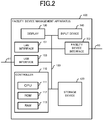
- the hardware configuration of the facility-device management apparatus 100 includes components illustrated in FIG. 2 . That is, the facility-device management apparatus 100 includes a controller 110 that controls overall operations of the facility-device management apparatus 100, a storage device 120 that stores data necessary for the controller 110 operations, a display 130 for providing information necessary for an operator of the facility-device management apparatus 100, and an input device 140 for accepting operation inputs made by the operator. For interfacing with other devices, the facility-device management apparatus 100 further includes a LAN interface 151, a facility device interface 152, and a USB interface 153. Each of the components (controller 110, storage device 120, display 130, input device 140, LAN interface 151, facility device interface 152, and USB interface 153) of the facility-device management apparatus 100 is mutually connected with one another via an internal bus 190.
- the controller 110 includes, for example, a central processing unit (CPU) 111, a read only memory (ROM) 112, and a random access memory (RAM) 113.
- the controller 110 controls the overall operations of the facility-device management apparatus 100 by executing the program stored in the ROM 112 or the RAM 113. As necessary, the controller 110 retrieves data such as a program from the storage device 120, or saves data onto the storage device 120.
- the storage device 120 includes a storage device such as a hard disk drive, flash memory, and/or the like and stores, in accordance with a control of the controller 110, data necessary for running the facility-device management apparatus 100.
- the display 130 includes a display device that is a liquid crystal display, a cathode ray tube, or the like and displays information to be presented to the operator of the facility-device management apparatus 100.
- the input device 140 includes a keyboard, mouse, and/or the like and accepts operation inputs made by the operator and provides the controller 110 with the operation inputs.
- the display 130 presents, to the operator of the facility-device management apparatus 100, information necessary for monitoring and controlling the facility devices.
- the input device 140 accepts operation inputs made by the operator for monitoring and controlling the facility devices and provides the controller 110 with the operation inputs.
- the facility-device management apparatus 100 includes a device, represented by the liquid crystal touch panel, that realizes both the function of displaying a screen and the function of accepting an operation with respect to the screen that is displayed, and this device may provide the function of the display 130 together with the function of the input device 140.
- the LAN interface 151 has a function of connecting the facility-device management apparatus 100 to a LAN that is compliant with protocol such as Ethernet (registered trademark) and TCP/IP.
- the facility-device management apparatus 100 transmits the operation data to the remote monitoring server 300 via the LAN interface 151.
- the facility device interface 152 connects the facility-device management apparatus 100 to the facility device network 90.
- the facility-device management apparatus 100 is connected to each of the facility devices via the facility device network 90 and acquires operation data of each of the facility devices.
- the facility device network 90 may be a general-use LAN configurable using any protocol or may be a network using a specific protocol.
- the USB interface 153 connects the facility-device management apparatus 100 to the relay device 200 via the connection line 91.
- the connection line 91 is a USB standard based general-purpose cable.
- the facility-device management apparatus 100 via the connection line 91, transmits data to the relay device 200 and receives data transmitted by the relay device 200.
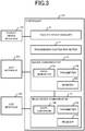
- the controller 110 implements the functional components illustrated in FIG 3 , as internal functions of the facility-device management apparatus 100. That is, the controller 110 includes a facility device manager 11 for managing each of the facility devices via the facility device interface 152, a transmission destination setter 12 for setting a transmission destination for the operation data, a server communicator 13 for communicating with the remote monitoring server 300 via the LAN interface 151, and a relay device communicator 14 for communicating with the relay device 200 via the USB interface 153.
- the facility device manager 11 manages each of the facility devices connected via the facility device interface 152 and the facility device network 90 to the facility device manager 11. Specifically, the facility device manager 11, on a cyclical basis, acquires, from each of the facility devices, data indicating the running state (power consumption, running environment (set temperature and airflow strength), and the like) of the corresponding facility device and stores the acquired data as operation data.
- the facility device manager 11 acquires error information transmitted by a facility device when an error occurs in the facility device, and stores the error information as operation data and also stores the error information as operation data.
- facility device manager 11 may acquire data indicating the running state from each of the facility devices based on operation details inputted via the input device 140.
- the facility device manager 11 may also display the operation data on the display 130 based on inputted operation details.
- the transmission destination setter 12 sets the transmission destination for the operation data of the facility-device management apparatus 100.
- the storage device 120 which is described in detail below, stores information indicating the destination of the operation data.
- the server communicator 13 transmits the stored operation data to the remote monitoring server 300 via the LAN interface 151.
- the server communicator 13 includes a data generator 13a that generates TCP/IP protocol-compliant data (first-protocol transmission data) based on the stored operation data, a transmitter 13b that transmits data of the TCP/IP protocol via the LAN interface 151, and a receiver 13c that receives data of the TCP/IP protocol via the LAN interface 151.
- the data generator 13a extracts, from the operation data stored in the storage device 120, data to be reported to the remote monitoring server 300. Any extraction criteria may be used.
- the data generator 13a for example, extracts from the stored operation data, data of a particular period of time including the point of time when extraction processing is performed (for example, a period of time from one week before the point of time of extraction to the point of time of extraction) or data not yet reported to the remote monitoring server 300.
- the data generator 13a generates data (first-protocol transmission data) based on TCP/IP protocol to be transmitted to the remote monitoring server 300 by modifying the data to conform to the format of TCP/IP protocol (affixing a header that conforms to TCP/IP protocol, for example).
- the transmitter 13b transmits data of the TCP/IP protocol via the LAN interface 151. More particularly, the transmitter 13b transmits the data that is generated by the data generator 13a based on the operation data. Further, the receiver 13c receives data of TCP/IP protocol via the LAN interface 151.
- the server communicator 13 Upon the data generator 13a generating the TCP/IP protocol-compliant data that is to be transmitted remote monitoring server 300, the server communicator 13 fetches, from the storage device 120, the information indicating the transmission destination of the operation data set by the transmission destination setter 12. As long as fetched information contains the information indicating the remote monitoring servicer 300 as the transmission destination, the data generated by the data generator 13a is transmitted by the server communicator 13, via the transmitter 13b. Conversely, when the fetched information does not contain the information indicating the remote monitoring server 300 as the transmission destination, the server communicator 13 transmits the data generated by the data generator 13a to the relay device communicator 14.
- the relay device communicator 14 performs communication with the relay device 200 via the USB interface 153 and the connection line 91. More particularly, the relay device communicator 14 receives the data transmitted by the server communicator 13, performs protocol conversion, and then transmits the converted data to the relay device 200. In order to implement these functions, the relay device communicator 14 includes a data converter 14a that converts TCP/IP protocol-compliant data into USB protocol-compliant data and vice versa. The relay device communicator 14 also includes a transmitter 14b that transmits data by USB protocol to the relay device 200 via the USB interface 153 and a receiver 14c that receives data by USB protocol from the relay device 200 via the USB interface 153.
- the data converter 14a receives the data (TCP/IP protocol-compliant data) transmitted by the server communicator 13 and converts the received data into USB protocol format data.
- the data transmitted by the server communicator 13 is TCP/IP protocol-compliant data generated by the data generator 13a.
- the data converter 14a analyzes the received data, and separates, from among the analyzed data, a portion corresponding to the operation data to be transmitted to the remote monitoring server 300 and a portion that is distinctly TCP/IP protocol (TCP/IP protocol header, delimiters and the like).
- the data converter 14a discards the portion that is distinctly TCP/IP protocol, and then adds a header to the portion corresponding to the operation data to be transmitted to the remote monitoring server 300, so as to be data in a USB protocol compliant format. In this manner, the data converter 14a converts the TCP/IP-compliant protocol data into USB protocol-compliant data.
- the transmitter 14b and the receiver 14c communicate with the relay device 200 via the USB interface 153 and the connection line 91 using USB protocol. More particularly, the transmitter 14b transmits to the relay device 200 the data converted by the data converter 14a into USB protocol data. Also, the receiver 14c receives the data transmitted by the relay device 200.
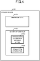
- the facility-device management apparatus 100 stores the data indicated in FIG. 4 into the storage device 120. That is, the storage device 120 stores operation data 121 containing the operation information of the facility device, and stores server information 122 containing the information regarding the remote monitoring server 300 that is the report destination of operation data.
- the operation data 121 is data containing operation information of facility devices managed by the facility-device management apparatus 100.
- the facility-device management apparatus 100 uses the function of the facility device manager 11 to acquire information regarding operation from each of the facility devices and store the acquired information into the operation data 121.
- the operation data 121 contains information of, for example, a facility device regarding the starting of operation and stopping of operation, operation modes (cooling and heating, for example), setting temperature, indoor temperature, and event information indicating when an event, such as an error, occurred, and also contains detail data that is used when performing maintenance on a facility device.
- the facility device manager 11, on a periodic basis or when an event occurs acquires operation-related information from a facility device, and then updates the operation data 121.
- the data generator 13a refers to the operation data 121 to generate report data to be reported to the remote monitoring server 300.
- the server information 122 is data containing information for transmitting report data generated based on the operation data 121 to the remote monitoring server 300 by the facility-device management apparatus 100.
- the server information 122 contains a transmission destination address setting 122a and connection information 122b.
- the transmission destination address setting 122a is data indicating information set as a destination of the report data. For example, when an Internet Protocol (IP) address of the remote monitoring server 300 is contained in the transmission destination address setting 122a, the server communicator 13 transmits data of TCP/IP protocol generated based on the operation data 121, via the LAN interface 151. Also, the data contained in the transmission destination address setting 122a is not limited to IP addresses. A uniform resource locator (URL), indicating the location of the remote monitoring server 300 on the Internet, may be contained in the transmission destination address setting 122a, for example.
- IP Internet Protocol
- URL uniform resource locator
- the server communicator 13 does not transmit report data generated by the data generator 13a to the outside via the LAN interface 151.
- the local loopback address is a type of IP address that indicates the transmission destination is the apparatus itself.
- the server communicator 13 transmits the report data generated by the data generator 13a to the relay device communicator 14 inside the apparatus itself (facility-device management apparatus 100).
- the relay device communicator 14 receives and converts the report data TCP/IP protocol-compliant report data into data of USB protocol-compliant format and then forwards the data by USB protocol to the relay device 200 via the USB interface 153 (and connection line 91). That is, when the local loopback address is contained in the transmission destination address setting 122a, the facility-device management apparatus 100a transmits the report data to the relay device 200 via the USB interface 153, instead of transmitting the report data to the remote monitoring server 300 via the LAN interface 151.
- the facility-device management apparatus 100 includes the previously described transmission destination setter 12 and provides the operator with a way to input data of the transmission destination address setting 122a. That is, the transmission destination setter 12 contains information input by the operator via the input device 140 into the transmission destination address setting 122a.
- the transmission destination setter 12 sets the facility-device management apparatus 100 to transmit the report data to the remote monitoring server 300.
- the transmission destination setter 12 sets the facility-device management apparatus 100 not to transmit the report data to the remote monitoring server 300.
- the transmission destination setter 12 functions as setting means for setting whether or not the facility-device management apparatus 100 is to transmit report data to the remote monitoring server 300. Also, the transmission destination setter 12 may be regarded as selection means for selecting which of the remote monitoring server 300 and the relay device 200 is to be transmitted the report data.
- the connection information 122b is data necessary for transmitting report data to the remote monitoring server 300.
- the connection information 122b contains information necessary for connecting to the remote monitoring server 300, for example, authentication information (username and password) a port number, an application layer protocol such as Hypertext Transfer Protocol (HTTP) or Simple Mail Transfer Protocol (SMTP), and the host name of the facility-device management apparatus 100.
- HTTP Hypertext Transfer Protocol
- SMTP Simple Mail Transfer Protocol
- the transmitter 13b of the server communicator 13 When the transmitter 13b of the server communicator 13 is to transmit the report data to the remote monitoring server 300, the transmitter 13b appropriately refers to the connection information 122b and either adds to the report data any data that is necessary, or transmits the necessary data prior to transmitting the report data.
- the transmitter 14b of the relay device communicator 14 when the transmitter 14b of the relay device communicator 14 is to transmit report data to the relay device 200, the transmitter 14b likewise refers to the connection information 122b and either adds to the report data any data that is necessary, or transmits the necessary data prior to transmitting the report data.
- the hardware configuration of the relay device 200 includes components illustrated in FIG. 5 . That is, the relay device 200 includes a controller 210 that controls overall operations of the relay device 200, a storage device 220 that stores data information necessary for the controller 210 operations, a display 230 for providing information necessary for an operator of the relay device 200, and an input device 240 for accepting operation inputs made by the operator. For interfacing with other devices, the relay device 200 also includes a LAN interface 251 and a USB interface 252. Each of the components (controller 210, storage device 220, display 230, input device 240, LAN interface 251, and USB interface 252) of the relay device 200 is mutually connected with one another via an internal bus 290.
- the controller 210, the display 230, the input device 240, and the internal bus 290 are the same as the identically named hardware components in the facility-device management apparatus 100, and a description thereof is therefore omitted.
- the LAN interface 251 has a function of connecting the relay device 200 to a LAN that is compliant with protocol such as Ethernet (registered trademark) and TCP/IP.
- the relay device 200 transmits report data to the remote monitoring server 300 via the LAN interface 251. Further, the relay device 200 receives data, via the LAN interface 251, from another device connected to the intra-facility LAN 92 or from yet another device connected with the relay device 200 via the Internet 93.
- the USB interface 252 connects the relay device 200 with the facility-device management apparatus 100 via the connection line 91.
- the facility-device management apparatus 100 via the connection line 91, transmits data to the relay device 200 and receives data transmitted by the relay device 200.
- the storage device 220 includes a storage device such as a hard disk drive, flash memory, and/or the like and stores, in accordance with a control of the controller 210, data necessary for running the relay device 200. More particularly, the storage device 220 stores security criteria 221 and a server address setting 222.
- the security criteria 221 contains information indicating what data among the data received by the relay device 200 via the LAN interface 251 may be forwarded to the facility-device management apparatus 100.
- the security criteria may be set such that only acknowledgement data from the remote monitoring server 300 in response to report data transmitted by the relay device 200, via the LAN interface 251, to the remote monitoring server 300 may be forwarded to the facility-device management apparatus 100.
- only data associated with verification of the remote monitoring server 300 may be forwarded to the relay-device management apparatus 100.
- the relay device 200 may use any criteria as the security criteria 221.
- the server address setting 222 is information indicating the location on the Internet of the remote monitoring server 300 that is the destination of the report data.
- the server address setting 222 contains the IP address or the URL of the remote monitoring server 300.
- the controller 210 implements each of the functional components illustrated in FIG. 6 , as the internal functions of the relay device 200. That is, the controller 210 includes a forwarder 21 that converts report data received from the relay device 200 into a TCP protocol format and transmits the data of TCP protocol to the remote monitoring server 300. Further, the controller 210 includes a protector 22 that extracts, from the data received by the LAN interface 251, data (secure data) that meets the security criteria 221, converts the extracted data into the USB protocol format, and then transmits the USB protocol format data via the USB interface 252.
- the forwarder 21 receives report data from the relay device 200 via the USB interface 252. Further, upon receipt of the report data, the forwarder 21 fetches the server address setting 222 of the storage device 220 and acquires the IP address of the remote monitoring server 300. The forwarder 21 converts the received report data (USB protocol format) into TCP/IP protocol format. When doing so, the IP address acquired from the remote monitoring server 300 is added to the portion, indicating the transmission destination IP address, in the header of the report data. The forwarder 21 transmits the report data that is in TCP/IP protocol format to the network via the LAN interface 251. The transmitted report data reaches the remote monitoring server 300 via the intra-facility LAN 92.
- the protector 22 extracts the data (secure data) that meets the security criteria 221 from the data received by the LAN interface 251 and transmits the extracted data to the facility-device management apparatus 100 via the USB interface 252.
- the security criteria 221 is set such that only acknowledgement data from the remote monitoring server 300, in response to report data transmitted by the relay device 200, may be forwarded to the remote monitoring server 300
- the protector 22 transmits, via the USB interface 252, data received only when the received data is acknowledgement data from the remote monitoring server 300.
- the protector 22 fetches the data from the storage device 220 when, for example, the relay device 200 is powered on.
- the protector 22 Upon receipt of data via the LAN interface 251, the protector 22 extracts data that meets the fetched secure data criteria and transmits the extracted data via the USB interface 252 to the facility-device management apparatus 100.
- the control system 1 transmits, to the remote monitoring server 300, the report data (first protocol data) generated based on the operation data acquired from the facility device .
- the relay device 200 that includes the protector 22 extracts data that meets the security criteria 221 and transmits the extracted data to the facility-device management apparatus 100. Since the facility-device management apparatus 100 is not directly connected to the Internet 93 and only receives data extracted in the relay device 200, a high security level can be easily maintained.
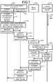
- FIG. 7 is a diagram illustrating the flow of data occurring when the facility-device management apparatus 100 reports operation data to the remote monitoring server 300 via the relay device 200.
- the transmission destination address setting 122a of the facility-device management apparatus 100 contains data indicating the local loopback address. That is, for the case indicated in FIG. 7 , the facility-device management apparatus 100 is set not to transmit the first protocol report data to the remote monitoring server 300.
- the facility-device management apparatus 100 When an event (such as arrival of a transmission deadline, an operation input by the operator requesting transmission of report data, or detection of an error) setting for report data to be generated occurs, the facility-device management apparatus 100 generates, based on the operation data 121, report data (first protocol data) that is to be reported to the remote monitoring server 300. The facility-device management apparatus 100 transmits the operation data to the remote monitoring server 300 via the relay device 200 in accordance with the data flow illustrated in FIG. 7 .
- report data first protocol data
- the server communicator 13 of the facility-device management apparatus 100 acquires the transmission destination address setting (step S101).
- the server communicator 13 refers to the transmission address setting 122a in the storage device 120 and acquires information (in this case, the local loopback address) indicating the transmission destination of the report data.
- the server communicator 13 establishes a connection with the relay device communicator 14 (step S102). Since the acquired information indicating the transmission destination of the report data is information indicating the apparatus itself (that is, the relay device communicator 14), the server communicator 13 transmits, to the relay device communicator 14 in the apparatus itself, a signal indicating connection request. The relay device communicator 14 acknowledges the received signal indicating connection request and transmits a signal indicating connection permission. The server communicator 13 establishes connection with the relay device communicator 14 upon completion of this process.
- the server communicator 13 transmits the operation data to the relay device communicator 14 (step S103).
- the server communicator 13 transmits report data generated based on TCP/IP protocol to the relay device communicator 14.
- the relay device communicator 14 performs protocol conversion on the received report data (step S104).
- the relay device communicator 14 extracts, from the report data that is TCP/IP protocol format, the data corresponding to the operation data.
- the relay device communicator 14 modifies (affixes a proper header, for example) the extracted data such that the data conforms to USB protocol.
- the relay device communicator 14 transmits the operation data that is in a format compliant with USB protocol to the relay device 200 via the connection line 91 (step S105).
- the relay device 200 Upon receipt of the operation data, the relay device 200 performs protocol conversion on the received operation data (step S106).
- the relay device 200 modifies (deletes the USB protocol header and affixes the proper header) the USB protocol-compliant formatted operation data (second-protocol transmission data) to conform to TCP/IP protocol.
- the relay device 200 also fetches the server address setting 222 from the storage device 220 and inserts the server address setting 222 into the transmission destination address of the TCP/IP header.
- the relay device 200 establishes connection with the remote monitoring server 300 (step S107).
- the relay device 200 fetches the server address setting 222 from the storage device 220 and acquires information indicating the location of the remote monitoring server 300 on the Internet.
- the relay device 200 transmits, based on the acquired information, a signal indicating a connection request, to the remote monitoring server 300.
- the remote monitoring server 300 acknowledges the received signal indicating a connection request and transmits a signal indicating connection permission.
- the relay device 200 establishes connection with the remote monitoring server 300.
- the relay device 200 transmits, to the remote monitoring server 300, the operation data converted into a format that conforms to TCP/IP protocol (step S108).
- the remote monitoring server 300 having received the operation data from the relay device 200 transmits an acknowledgement signal in response to the received operation data (step S109).
- the relay device 200 Upon receipt of the acknowledgement signal from the remote monitoring server 300, the relay device 200 performs protocol conversion on the acknowledgement signal (step S110). The relay device 200 converts the acknowledgement signal from TCP/IP protocol format to USB protocol format.
- the relay device 200 transmits the acknowledgement signal converted into USB protocol to the relay device communicator 14 of the facility-device management apparatus 100 via the connection line 91 (step S111).
- the relay device communicator 14 Upon receipt of the acknowledgement signal from the relay device 200, the relay device communicator 14 performs protocol conversion on the acknowledgement signal (step S112). The relay device communicator 14 converts the received acknowledgement signal from USB protocol format to TCP/IP protocol format.
- the relay device communicator 14 transmits, to the server communicator 13, the acknowledgement signal converted into TCP/IP protocol format (step S113).
- the server communicator 13 transmits, to the remote monitoring server 300, the report data (first-protocol transmission data) generated based on the operation data and receives the acknowledgement signal from the remote monitoring server 300. That is, the control system 1 reports the report data generated based on the operation data to the remote monitoring server 300 by performing this processing.
- the server communicator 13 performs a process corresponding to the aforementioned steps S101 to S103 and step S113. That is, the server communicator 13, in this case, acquires the IP address or URL of the remote monitoring server 300 from the transmission destination address setting 122a (corresponding to step S101), establishes connection with the remote monitoring server 300 (corresponding to step S102), and transmits the report data to the remote monitoring server 300 (corresponding to step S103). Upon receipt of the transmitted report data, the remote monitoring server 300 transmits an acknowledgement signal to the server communicator 13 (corresponding to step S113).
- the server communicator 13 When the transmission destination address setting 122a contains information (IP address or URL) indicating the location of the remote monitoring server 300 on the Internet (that is, when a setting is made to transmit report data by TCP/IP protocol to the remote monitoring server 300), the server communicator 13 transmits the report data via the LAN interface 151 to the remote monitoring server 300. Conversely, when the transmission destination address setting 122a contains a local loopback address (that is, when a setting is made not to transmit the report data by TCP/IP protocol to the remote monitoring server 300), the server communicator 13 transmits the report data to the relay device communicator 14. The relay device communicator 14 converts the received report data received in TCP/IP protocol into report data compliant with USB protocol, and transmits the report data by USB protocol to the relay device 200 via the USB interface 153.
- any protocol may be used in the application layer.
- acceptable protocols include Hypertext Transfer Protocol (HTTP), Simple Mail Transfer Protocol (SMTP), and File Transfer Protocol (FTP).
- HTTP Hypertext Transfer Protocol
- SMTP Simple Mail Transfer Protocol
- FTP File Transfer Protocol
- the control system 1 according to the present background example may implement a protocol that uses User Datagram Protocol (UDP) instead of TCP.
- UDP User Datagram Protocol
- the transmission destination setter 12 adds, to the transmission destination address setting 122a, the content inputted via the input device 140 by the operator of the facility-device management apparatus 100, and thereby sets whether or not the facility-device management apparatus 100 is to transmit the report data to the remote monitoring server 300.
- the transmission destination setter 12 may instead determine whether the LAN interface 151 of the facility-device management apparatus 100 is connectable or not-connectable to the remote monitoring server 300, and when determining that connection is not possible, the transmission destination setter 12 may set such that the facility-device management apparatus 100 does not transmit the report data to the remote monitoring server 300.
- the facility-device management apparatus 100 in addition to the transmission destination address setting 122a, the facility-device management apparatus 100 also stores, into the storage device 120, direct transmission flag data indicating whether or not the facility-device management apparatus 100 is to transmit the report data to the remote monitoring server 300.
- the transmission destination setter 12 also stores the IP address or the URL of the remote monitoring server 300 into the transmission destination address setter 122a.
- the transmission destination setter 12 verifies connectivity with the remote monitoring server 300 via the LAN interface 151. Specifically, the transmission destination setter 12 issues a type of command called ping-command to the IP address stored in the transmission destination address setting 122a.
- the transmission destination setter 12 When an arrival acknowledgement in response to the issued ping-command is returned from the destination address, the transmission destination setter 12 sets the direct transmission flag data to ON. Conversely, if an arrival acknowledgement is not returned from the destination address in response to the ping-command within a given time period, the transmission destination setter 12 sets the direct transmission flag data to OFF.
- the server communication 13 After generating the report data, the server communication 13 refers to the direct transmission flag data and determines whether or not the facility-device management apparatus 100 is to transmit the report data to the remote monitoring server 300. When the direct transmission flag data is set as ON, the server communicator 13 transmits the report data via the LAN interface 151. Conversely, when the direct transmission flag data is set as OFF, the server communicator 13 transmits the report data to the relay device communicator 14.
- the transmission destination setter 12 stores, into the storage 120, information indicating whether or not the facility-device management apparatus 100 is to transmit the report data to the remote monitoring server 300.
- the transmission destination setter 12 may include a physical switch that may be toggled between ON and OFF to switch between a transmission and a non-transmission of the report data to the remote monitoring server 300.
- the operator of the facility-device management apparatus 100 for example, can toggle the switch to switch between transmission via the relay device 200 and transmission via the LAN interface 151, of the report data.
- the relay device 200 that ensures security connects to the network (intra-facility LAN 92) connected to the Internet, whereas the facility-device management apparatus 100 does not connect directly to the intra-facility LAN 92.
- Using the control system 1 according to the present background example therefore can reduce the risk of the facility-device management apparatus 100 being attacked directly by an unauthorized user from an external device.
- connection line 91 is a USB protocol dedicated connector that makes hacking into communications between the facility-device management apparatus 100 and the relay device 200 difficult from another device. Therefore, a high security level can be maintained in the network (connection line 91, facility-device management apparatus 100, and facility device network 90, and each facility device) beyond the relay device 200.
- the facility-device management apparatus 100 does not have an IP address in the intra-facility LAN 92. Therefore, replacing the facility-device management apparatus 100 does not result in extra work for the network administrator of the intra-facility LAN 92, thereby reducing the administration workload.
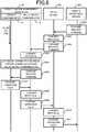
- Embodiment 1 In the background example, an example is described in which the control system 1, triggered by the occurrence of an internal event (such as arrival of a transmission deadline, an operation input by an operator, or occurrence of an event, for example), generates report data and transmits the report data to the remote monitoring server 300. However, the control system 1 may generate report data in response to a request from the remote monitoring server 300 instead and transmit the report data to the remote monitoring server 300. In an embodiment of the invention, an example is described in which the control system 1 transmits report data in response to a request from remote monitoring server 300.
- an internal event such as arrival of a transmission deadline, an operation input by an operator, or occurrence of an event, for example
- the relay device 200 receives the transmitted request command.
- the relay device 200 refers to the security criteria 221 and when the received request command meets the security criteria 221, the relay device 200 performs protocol conversion on the received request command (step S202).
- the relay device 200 converts the received request command from TCP/IP protocol format to USB protocol format.
- the relay device 200 transmits the request command converted into USB protocol format to the relay device communicator 14 via the connection line 91 (step S203).
- the relay device communicator 14 Upon receipt of the request command, the relay device communicator 14 performs protocol conversion on the received request command (step S204). The relay device communicator 14 converts the received request command from USB protocol format into TCP/IP protocol format.
- the relay device communicator 14 establishes connection with the server communicator 13 (step S205).
- the relay device communicator 14 transmits to the server communicator 13 a signal indicating a connection request.
- the server communicator 13 acknowledges the received signal indicating the connection request and transmits a signal indicating connection permission.
- the relay device communicator 14 establishes connection with the server communicator 13.
- the relay device communicator 14 transmits the request command converted into TCP/IP protocol format to the server communicator 13 (step S206).
- the server communicator 13 receives the request command, generates operation data in accordance with the request command, and transmits the operation data to the relay device communicator 14 (step S207).
- the server communicator 13 analyzes the received request command and determines the kind of data the remote monitoring server 300 is requesting to be extracted based on the operation data 121 and transmitted.
- the server communicator 13 generates, based on the operation data 121, operation data in accordance with the request command and generates TCP/IP protocol operation data.
- the server communicator 13 transmits the generated operation data to the relay device communicator 14.
- the relay device communicator 14 Upon receipt of the operation data, the relay device communicator 14 performs protocol conversion on the received operation data (step S208). The relay device communicator 14 converts the received operation data from TCP/IP protocol format to USB protocol format.
- the relay device communicator 14 transmits the operation data converted into USB protocol format to the relay device 200 via the connection line 91 (step S209).
- the relay device 200 Upon receipt of the operation data, the relay device 200 performs protocol conversion on the received operation data (step S210). The relay device 200 converts the received operation data from USB protocol format into TCP/IP protocol format.
- the relay device 200 transmits the operation data converted into TCP/IP protocol format to the remote monitoring servicer 300 (step S211). Through this process, the operation data requested by the remote monitoring server 300 is transmitted from the control system 1 to the remote monitoring server 300.
- the relay device 200 extracts, from the data received via the LAN interface 251, secure data that meets the security criteria 221 and transmits the extracted secure data to the facility-device management apparatus 100. This enables the facility-device management apparatus 100 to be protected from outside threats.
- the relay device 200 includes a function to appropriately accept request commands from the outside.
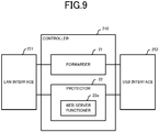
- the controller 210 of the relay device 200 according to Embodiment 1 implements a web server functioner 22a as a portion of the protector 22 as indicated in FIG. 9 .
- the web server functioner 22a communicates with the web browser running on another device (remote monitoring server 300) and accepts a request command directed to the facility-device management apparatus 100.
- the web server functioner 22a extracts, from the received request command, the secure data that meets the security criteria 221 and transmits the extracted secure data to the facility-device management apparatus 100.
- the inclusion of the web server functioner 22a within the protector 22 enables, for example, easy implementation of a security framework used by a common web server.
- an existing web server already includes username and password-based authentication system.
- the web server functioner 22a By implementing a username and password-based authentication system with the web server functioner 22a, any request command without a correct username and password is discarded, thereby protecting the facility-device management apparatus 100.
- the correct username and password are stored as a set in the security criteria 221.
- common web servers can communicate information not only with other devices via a network but also through a web browser running on a device itself.
- setting the web server functioner 22a to communicate with a web browser running by the device itself (relay device 200) enables not the remote monitoring server 300 but rather the relay device 200 to acquire operation data.
- the operator of the relay device 200 can conveniently confirm the operation data of each facility device, via the display 130 provided by the relay device 200.
- connection line 91 is a USB-based cable connection.
- any universal standard-based connection can be used as the connection line 91.
- acceptable connections may include Institute of Electrical and Electronics Engineers (IEEE)-based connections 1394, Recommended Standard (RS) 232C-based connections, and Bluetooth (registered trademark)-based connections.
- IEEE Institute of Electrical and Electronics Engineers
- RS Recommended Standard
- Bluetooth registered trademark
- the remote monitoring server 300 receives operation data transmitted by the relay device 200.
- a proxy server may be installed between the relay device 200 and the remote monitoring server 300.
- the relay device 200 transmits operation data to the proxy server and the proxy server transmits the received operation data to the remote monitoring server 300.
- the programs executed by the facility-device management apparatus 100 or the relay device 200 in the aforementioned embodiments may be stored in a computer-readable recording medium such as a compact disk read-only memory (CD-ROM), a digital versatile disc (DVD), a magneto-optical disk (MO), a universal serial bus (USB) memory and a memory card and distributed
- a computer-readable recording medium such as a compact disk read-only memory (CD-ROM), a digital versatile disc (DVD), a magneto-optical disk (MO), a universal serial bus (USB) memory and a memory card and distributed
- CD-ROM compact disk read-only memory
- DVD digital versatile disc
- MO magneto-optical disk
- USB universal serial bus
- the above-described program may be stored on a storage device of a server device on a communication network, such as the Internet, to enable the program to be downloaded to the computer, for example by superimposing the program onto a carrier wave.
- the above-described processing can be achieved even by execution while the program is transferred through the communication network.
- the above-described processing can be achieved by executing all or part of the program on the server device, and executing the program while sending and receiving by the computer the information relating to such processing through the communication network.
- the non-OS portion alone may be stored in the above-described recording medium and distributed, or alternatively, may be, for example, downloaded to the computer.
- the present disclosure is suitable for a control system for reporting operation data of facility devices installed in a facility such as a building.
Landscapes
- Engineering & Computer Science (AREA)
- Signal Processing (AREA)
- Computer Networks & Wireless Communication (AREA)
- Automation & Control Theory (AREA)
- Computer Security & Cryptography (AREA)
- Computing Systems (AREA)
- Health & Medical Sciences (AREA)
- General Health & Medical Sciences (AREA)
- Medical Informatics (AREA)
- Multimedia (AREA)
- Selective Calling Equipment (AREA)
- Data Exchanges In Wide-Area Networks (AREA)
- Telephonic Communication Services (AREA)
- Testing And Monitoring For Control Systems (AREA)
- Computer And Data Communications (AREA)
Claims (8)
- Appareil de gestion de dispositif d'installation (100) comprenant :un moyen de réglage (12) pour définir s'il faut transmettre ou non des données de transmission de premier protocole générées d'après des données de fonctionnement acquises depuis un dispositif d'installation et conformes à un premier protocole, à un serveur de surveillance à distance (300) ;un premier moyen de transmission (13) pour transmettre les données de transmission de premier protocole au serveur de surveillance à distance (300) lorsque les données de transmission de premier protocole sont définies comme devant être transmises au serveur de surveillance à distance (300) ; etun deuxième moyen de transmission (14) pour, lorsque les données de transmission de premier protocole sont définies comme ne devant pas être transmises au serveur de surveillance à distance (300), convertir les données de transmission de premier protocole en données de transmission de deuxième protocole conformes à un deuxième protocole, et transmettre les données de transmission de deuxième protocole à un dispositif relais (200) connecté au serveur de surveillance à distance (300) via un réseau (92) configuré d'après le premier protocole,caractérisé en ce que l'appareil de gestion de dispositif d'installation comprend en outre :un moyen de réception (14c) pour recevoir des données sécurisées extraites par le dispositif relais (200) d'après des critères de sécurité, les données sécurisées étant extraites de données de réception reçues par le dispositif relais (200) via le réseau (92) ; etun moyen de génération de données (13a) pour générer les données de transmission de premier protocole lorsque les données sécurisées reçues contiennent un signal de commande adressé à l'appareil de gestion de dispositif d'installation (100).
- Appareil de gestion de dispositif d'installation (100) selon la revendication 1, caractérisé en ce que le moyen de réglage (12) est configuré pour déterminer si le premier moyen de transmission (13) peut être connecté ou non au serveur de surveillance à distance (300), et lorsqu'il est déterminé que le premier moyen de transmission (13) ne peut pas être connecté au serveur de surveillance à distance (300), pour définir de ne pas transmettre les données de transmission de premier protocole au serveur de surveillance à distance (300).
- Appareil de gestion de dispositif d'installation (100) selon la revendication 1 ou 2, caractérisé en ce que le deuxième moyen de transmission (14) est configuré pour transmettre les données de transmission de deuxième protocole au dispositif relais (200) par une connexion dédiée configurée d'après le deuxième protocole.
- Système de commande (1), caractérisé en ce qu'il comprend :l'appareil de gestion de dispositif d'installation (100) selon l'une quelconque des revendications 1 à 3 ; etle dispositif relais (200) configuré pour communiquer avec le serveur de surveillance à distance (300) via un réseau (92) configuré d'après le premier protocole, le dispositif relais (200) étant en outre configuré pour communiquer avec l'appareil de gestion de dispositif d'installation (100) via une connexion configurée d'après le deuxième protocole,dans lequel le dispositif relais (200) comprendun moyen de réacheminement (21) pour recevoir les données de transmission de deuxième protocole en provenance de l'appareil de gestion de dispositif d'installation (100), convertir les données de transmission de deuxième protocole en données de transmission de premier protocole, et transmettre les données de transmission de premier protocole au réseau (92).
- Système de commande (1) selon la revendication 4, caractérisé en ce que
le dispositif relais (200) comprend en outre un moyen de protection (22) pour extraire, de données de réception de premier protocole reçues via le réseau (92), des données sécurisées qui satisfont des critères de sécurité, et transmettre les données sécurisées à l'appareil de gestion de dispositif d'installation (100), et
l'appareil de gestion de dispositif d'installation (100) comprend en outre un moyen de réception (14c) pour recevoir les données sécurisées en provenance du moyen de protection (22). - Système de commande (1) selon la revendication 5, caractérisé en ce que
le moyen de protection (22) comprend un moyen d'acceptation de commande (22a) pour extraire, des données de réception de premier protocole, les données sécurisées contenant un signal de commande adressé à l'appareil de gestion de dispositif d'installation (100), et transmettre les données sécurisées à l'appareil de gestion de dispositif d'installation (100), et
l'appareil de gestion de dispositif d'installation (100) est configuré pour générer la transmission de premier protocole lors d'une réception des données sécurisées contenant le signal de commande. - Système de commande (1) selon l'une quelconque des revendications 4 à 6, caractérisé en ce que le dispositif relais (200) est configuré pour communiquer avec l'appareil de gestion de dispositif d'installation (100) par une connexion dédiée configurée d'après le deuxième protocole.
- Système de commande (1) selon l'une quelconque des revendications 4 à 7, caractérisé en ce que le dispositif relais (200) comprend en outre un stockage (220) qui est configuré pour stocker des informations indiquant un emplacement du serveur de surveillance à distance (300).
Applications Claiming Priority (1)
| Application Number | Priority Date | Filing Date | Title |
|---|---|---|---|
| PCT/JP2015/075447 WO2017042879A1 (fr) | 2015-09-08 | 2015-09-08 | Système de commande et appareil de gestion de dispositif d'installation |
Publications (3)
| Publication Number | Publication Date |
|---|---|
| EP3349478A1 EP3349478A1 (fr) | 2018-07-18 |
| EP3349478A4 EP3349478A4 (fr) | 2018-09-12 |
| EP3349478B1 true EP3349478B1 (fr) | 2020-06-10 |
Family
ID=58239313
Family Applications (1)
| Application Number | Title | Priority Date | Filing Date |
|---|---|---|---|
| EP15903545.0A Active EP3349478B1 (fr) | 2015-09-08 | 2015-09-08 | Système de commande et appareil de gestion |
Country Status (5)
| Country | Link |
|---|---|
| US (1) | US10764080B2 (fr) |
| EP (1) | EP3349478B1 (fr) |
| JP (1) | JP6611810B2 (fr) |
| CN (1) | CN108028970B (fr) |
| WO (1) | WO2017042879A1 (fr) |
Families Citing this family (20)
| Publication number | Priority date | Publication date | Assignee | Title |
|---|---|---|---|---|
| US10178206B2 (en) * | 2015-11-10 | 2019-01-08 | Microsoft Technology Licensing, Llc | Multi-protocol gateway for connecting sensor devices to cloud |
| JP7122159B2 (ja) * | 2018-05-25 | 2022-08-19 | 三菱重工業株式会社 | データ処理システム、データ処理方法およびプログラム |
| JP7084218B2 (ja) * | 2018-06-13 | 2022-06-14 | 三菱重工業株式会社 | 情報中継装置、遠隔サービスシステム、情報中継方法及びプログラム |
| WO2020026452A1 (fr) * | 2018-08-03 | 2020-02-06 | 三菱電機株式会社 | Dispositif de gestion d'équipement, système de gestion d'équipement, procédé de gestion d'équipement, et programme |
| CN109379368B (zh) * | 2018-11-06 | 2021-07-06 | 国电电力发展股份有限公司 | 一种物理隔离的双网间数据交换设备及方法 |
| JP7280477B2 (ja) * | 2019-01-30 | 2023-05-24 | スター精密株式会社 | 中継器における通信ログ管理システム、中継器およびホスト装置 |
| CN110531943B (zh) * | 2019-08-07 | 2023-01-13 | 北京数衍科技有限公司 | 基于fpga的usb数据桥接方法 |
| US12301661B2 (en) | 2019-12-06 | 2025-05-13 | Zurn Water, Llc | Water management system and user interface |
| WO2021245845A1 (fr) * | 2020-06-03 | 2021-12-09 | 三菱電機ビルテクノサービス株式会社 | Dispositif de relais de communication et son procédé de réglage de connexion |
| US11488457B2 (en) | 2020-06-08 | 2022-11-01 | Zurn Industries, Llc | Cloud-connected occupancy lights and status indication |
| US11108865B1 (en) * | 2020-07-27 | 2021-08-31 | Zurn Industries, Llc | Battery powered end point device for IoT applications |
| US11153945B1 (en) | 2020-12-14 | 2021-10-19 | Zurn Industries, Llc | Facility occupancy detection with thermal grid sensor |
| KR102487895B1 (ko) * | 2020-12-18 | 2023-01-12 | 효성티앤에스 주식회사 | 가상 드라이버 기반 원격 구동 디지털 데스크, 이를 이용한 원격 금융 서비스 제공 시스템 및 그 방법 |
| US11594119B2 (en) | 2021-05-21 | 2023-02-28 | Zurn Industries, Llc | System and method for providing a connection status of a battery powered end point device |
| JP7682712B2 (ja) * | 2021-06-16 | 2025-05-26 | キヤノン株式会社 | 情報処理装置とその制御方法、及びプログラム |
| EP4369677B1 (fr) * | 2021-07-05 | 2026-02-11 | Panasonic Intellectual Property Corporation of America | Dispositif de relais d'informations de position, système d'acquisition d'informations de position, procédé de relais d'informations de position et programme |
| US11543791B1 (en) | 2022-02-10 | 2023-01-03 | Zurn Industries, Llc | Determining operations for a smart fixture based on an area status |
| US11514679B1 (en) | 2022-02-18 | 2022-11-29 | Zurn Industries, Llc | Smart method for noise rejection in spatial human detection systems for a cloud connected occupancy sensing network |
| US11555734B1 (en) | 2022-02-18 | 2023-01-17 | Zurn Industries, Llc | Smart and cloud connected detection mechanism and real-time internet of things (IoT) system management |
| US12541235B2 (en) * | 2023-05-24 | 2026-02-03 | Altera Corporation | Systems and methods with auxiliary control boards having interface devices |
Family Cites Families (14)
| Publication number | Priority date | Publication date | Assignee | Title |
|---|---|---|---|---|
| WO2002027640A2 (fr) * | 2000-09-29 | 2002-04-04 | Lifelink, Inc. | Systeme et procede pour communiquer par radio a un serveur central des donnees captees |
| US7136914B2 (en) * | 2001-08-06 | 2006-11-14 | Ricoh Company, Ltd. | System, computer program product and method for managing and controlling a local network of electronic devices |
| HK1052830A2 (en) | 2003-02-26 | 2003-09-05 | Intexact Technologies Limited | An integrated programmable system for controlling the operation of electrical and/or electronic appliances of a premises |
| JP4479173B2 (ja) | 2003-06-27 | 2010-06-09 | ダイキン工業株式会社 | 表示システム、表示プログラム、表示方法 |
| US20070143456A1 (en) | 2003-12-10 | 2007-06-21 | Alex Mashinsky | Exchange of centralized control data |
| JP4433935B2 (ja) * | 2004-08-19 | 2010-03-17 | パナソニック電工株式会社 | 中継親装置及び遠隔監視制御システム |
| JP4337891B2 (ja) | 2007-03-01 | 2009-09-30 | セイコーエプソン株式会社 | 記憶端末および情報処理システム |
| JP2013219656A (ja) * | 2012-04-11 | 2013-10-24 | Sony Corp | プロトコル変換装置及びプロトコル変換方法 |
| JP6022201B2 (ja) * | 2012-05-07 | 2016-11-09 | シャープ株式会社 | 遠隔制御システム、上記遠隔制御システムの設定方法、通信端末装置、およびサーバ装置 |
| US11610674B2 (en) * | 2013-03-14 | 2023-03-21 | Embecta Corp. | Direct CGM connectivity to a cloud storage network |
| JP6229142B2 (ja) * | 2013-03-29 | 2017-11-15 | パナソニックIpマネジメント株式会社 | 冷蔵庫及び冷蔵庫システム |
| CN105230037B (zh) | 2013-05-22 | 2018-09-04 | 三菱电机株式会社 | 监视系统、设备管理装置以及监视方法 |
| JP6343908B2 (ja) * | 2013-10-30 | 2018-06-20 | 東芝ライテック株式会社 | 通信システム |
| JP6354145B2 (ja) * | 2013-12-12 | 2018-07-11 | 富士通株式会社 | 中継装置、中継制御方法、及び、中継制御プログラム |
-
2015
- 2015-09-08 US US15/741,062 patent/US10764080B2/en active Active
- 2015-09-08 CN CN201580082819.XA patent/CN108028970B/zh active Active
- 2015-09-08 JP JP2017538503A patent/JP6611810B2/ja active Active
- 2015-09-08 EP EP15903545.0A patent/EP3349478B1/fr active Active
- 2015-09-08 WO PCT/JP2015/075447 patent/WO2017042879A1/fr not_active Ceased
Non-Patent Citations (1)
| Title |
|---|
| None * |
Also Published As
| Publication number | Publication date |
|---|---|
| CN108028970B (zh) | 2021-03-16 |
| CN108028970A (zh) | 2018-05-11 |
| US20180198639A1 (en) | 2018-07-12 |
| JPWO2017042879A1 (ja) | 2018-06-14 |
| EP3349478A4 (fr) | 2018-09-12 |
| EP3349478A1 (fr) | 2018-07-18 |
| US10764080B2 (en) | 2020-09-01 |
| JP6611810B2 (ja) | 2019-11-27 |
| WO2017042879A1 (fr) | 2017-03-16 |
Similar Documents
| Publication | Publication Date | Title |
|---|---|---|
| EP3349478B1 (fr) | Système de commande et appareil de gestion | |
| EP3300331B1 (fr) | Procédé, appareil et système de réponse dans une authentification informatique de réseau virtuel, et serveur mandataire | |
| JP5976210B2 (ja) | 監視システム、設備管理装置、監視方法及びプログラム | |
| CN103472779B (zh) | 智能家居楼宇控制系统及其接入空调系统的方法 | |
| KR100960586B1 (ko) | 네트워크 시스템 | |
| EP3229420A1 (fr) | Procédé pour établir une connexion persistante entre de multiples dispositifs intelligents et un serveur, et dispositif intelligent | |
| CN105337756A (zh) | 一种集中运维的方法及装置 | |
| US10523763B2 (en) | Communication device, communication method, controlled device, and non-transitory computer readable medium | |
| US20190373062A1 (en) | Terminal for remote monitoring system, program for remote monitoring, and remote monitoring system | |
| JP6996097B2 (ja) | 仲介装置、情報処理システム及びプログラム | |
| KR101996896B1 (ko) | 가상 디바이스 드라이버를 이용한 리소스 공유 방법 및 그 전자 디바이스 | |
| KR100357045B1 (ko) | 인터넷을 이용한 댁내 자동화 방법 및 시스템 | |
| KR20190089811A (ko) | 홈 네트워크 서비스를 제공하기 위한 장치 및 그 방법 | |
| US10225738B2 (en) | Remote operation system, relay apparatus, mobile communication apparatus, in-terminal server control method, and relay processing method | |
| CN106528074B (zh) | 信息终端的控制方法、程序以及应用系统 | |
| JP2013088995A (ja) | 保守作業支援装置 | |
| US9923769B2 (en) | Methods and systems for verifying installation of a device | |
| US9087185B2 (en) | Server device for transmitting and receiving data to and from client device through access point | |
| CN103036897A (zh) | 瘦客户端与服务器端之间基于远程桌面连接的通信方法 | |
| EP2819349A1 (fr) | Dispositif de communication, procédé de communication et dispositif de gestion | |
| US20230131484A1 (en) | Communication apparatus, program, communication method, information processing method, information processing apparatus, and communication system | |
| US10511671B2 (en) | Communication device, communication method, controlled device, and non-transitory computer readable medium | |
| CN103368956A (zh) | 一种服务端使用vnc的rfb协议安全通信方法及rfb代理服务器 | |
| KR20170025967A (ko) | 네트워크 패킷을 송수신 받을 수 있는 장치 및 그 방법 | |
| US20060282523A1 (en) | System and method for non-obtrusive monitoring and control of remote services and control gateways |
Legal Events
| Date | Code | Title | Description |
|---|---|---|---|
| STAA | Information on the status of an ep patent application or granted ep patent |
Free format text: STATUS: THE INTERNATIONAL PUBLICATION HAS BEEN MADE |
|
| PUAI | Public reference made under article 153(3) epc to a published international application that has entered the european phase |
Free format text: ORIGINAL CODE: 0009012 |
|
| STAA | Information on the status of an ep patent application or granted ep patent |
Free format text: STATUS: REQUEST FOR EXAMINATION WAS MADE |
|
| 17P | Request for examination filed |
Effective date: 20180215 |
|
| AK | Designated contracting states |
Kind code of ref document: A1 Designated state(s): AL AT BE BG CH CY CZ DE DK EE ES FI FR GB GR HR HU IE IS IT LI LT LU LV MC MK MT NL NO PL PT RO RS SE SI SK SM TR |
|
| AX | Request for extension of the european patent |
Extension state: BA ME |
|
| A4 | Supplementary search report drawn up and despatched |
Effective date: 20180813 |
|
| RIC1 | Information provided on ipc code assigned before grant |
Ipc: H04M 11/00 20060101ALI20180807BHEP Ipc: H04Q 9/00 20060101AFI20180807BHEP Ipc: H04L 29/08 20060101ALI20180807BHEP Ipc: H04L 12/28 20060101ALI20180807BHEP Ipc: H04M 3/00 20060101ALI20180807BHEP Ipc: H04L 29/06 20060101ALI20180807BHEP |
|
| DAV | Request for validation of the european patent (deleted) | ||
| DAX | Request for extension of the european patent (deleted) | ||
| STAA | Information on the status of an ep patent application or granted ep patent |
Free format text: STATUS: EXAMINATION IS IN PROGRESS |
|
| 17Q | First examination report despatched |
Effective date: 20190718 |
|
| RIC1 | Information provided on ipc code assigned before grant |
Ipc: H04M 11/00 20060101ALI20191112BHEP Ipc: H04M 3/00 20060101ALI20191112BHEP Ipc: H04L 12/28 20060101ALI20191112BHEP Ipc: H04L 29/08 20060101ALI20191112BHEP Ipc: H04Q 9/00 20060101AFI20191112BHEP Ipc: H04L 29/06 20060101ALI20191112BHEP |
|
| GRAP | Despatch of communication of intention to grant a patent |
Free format text: ORIGINAL CODE: EPIDOSNIGR1 |
|
| STAA | Information on the status of an ep patent application or granted ep patent |
Free format text: STATUS: GRANT OF PATENT IS INTENDED |
|
| INTG | Intention to grant announced |
Effective date: 20200107 |
|
| GRAS | Grant fee paid |
Free format text: ORIGINAL CODE: EPIDOSNIGR3 |
|
| GRAA | (expected) grant |
Free format text: ORIGINAL CODE: 0009210 |
|
| STAA | Information on the status of an ep patent application or granted ep patent |
Free format text: STATUS: THE PATENT HAS BEEN GRANTED |
|
| AK | Designated contracting states |
Kind code of ref document: B1 Designated state(s): AL AT BE BG CH CY CZ DE DK EE ES FI FR GB GR HR HU IE IS IT LI LT LU LV MC MK MT NL NO PL PT RO RS SE SI SK SM TR |
|
| REG | Reference to a national code |
Ref country code: GB Ref legal event code: FG4D |
|
| REG | Reference to a national code |
Ref country code: CH Ref legal event code: EP Ref country code: AT Ref legal event code: REF Ref document number: 1280114 Country of ref document: AT Kind code of ref document: T Effective date: 20200615 |
|
| REG | Reference to a national code |
Ref country code: DE Ref legal event code: R096 Ref document number: 602015054214 Country of ref document: DE |
|
| REG | Reference to a national code |
Ref country code: IE Ref legal event code: FG4D |
|
| REG | Reference to a national code |
Ref country code: LT Ref legal event code: MG4D |
|
| PG25 | Lapsed in a contracting state [announced via postgrant information from national office to epo] |
Ref country code: NO Free format text: LAPSE BECAUSE OF FAILURE TO SUBMIT A TRANSLATION OF THE DESCRIPTION OR TO PAY THE FEE WITHIN THE PRESCRIBED TIME-LIMIT Effective date: 20200910 Ref country code: GR Free format text: LAPSE BECAUSE OF FAILURE TO SUBMIT A TRANSLATION OF THE DESCRIPTION OR TO PAY THE FEE WITHIN THE PRESCRIBED TIME-LIMIT Effective date: 20200911 Ref country code: LT Free format text: LAPSE BECAUSE OF FAILURE TO SUBMIT A TRANSLATION OF THE DESCRIPTION OR TO PAY THE FEE WITHIN THE PRESCRIBED TIME-LIMIT Effective date: 20200610 Ref country code: SE Free format text: LAPSE BECAUSE OF FAILURE TO SUBMIT A TRANSLATION OF THE DESCRIPTION OR TO PAY THE FEE WITHIN THE PRESCRIBED TIME-LIMIT Effective date: 20200610 Ref country code: FI Free format text: LAPSE BECAUSE OF FAILURE TO SUBMIT A TRANSLATION OF THE DESCRIPTION OR TO PAY THE FEE WITHIN THE PRESCRIBED TIME-LIMIT Effective date: 20200610 |
|
| REG | Reference to a national code |
Ref country code: NL Ref legal event code: MP Effective date: 20200610 |
|
| PG25 | Lapsed in a contracting state [announced via postgrant information from national office to epo] |
Ref country code: HR Free format text: LAPSE BECAUSE OF FAILURE TO SUBMIT A TRANSLATION OF THE DESCRIPTION OR TO PAY THE FEE WITHIN THE PRESCRIBED TIME-LIMIT Effective date: 20200610 Ref country code: LV Free format text: LAPSE BECAUSE OF FAILURE TO SUBMIT A TRANSLATION OF THE DESCRIPTION OR TO PAY THE FEE WITHIN THE PRESCRIBED TIME-LIMIT Effective date: 20200610 Ref country code: BG Free format text: LAPSE BECAUSE OF FAILURE TO SUBMIT A TRANSLATION OF THE DESCRIPTION OR TO PAY THE FEE WITHIN THE PRESCRIBED TIME-LIMIT Effective date: 20200910 Ref country code: RS Free format text: LAPSE BECAUSE OF FAILURE TO SUBMIT A TRANSLATION OF THE DESCRIPTION OR TO PAY THE FEE WITHIN THE PRESCRIBED TIME-LIMIT Effective date: 20200610 |
|
| REG | Reference to a national code |
Ref country code: AT Ref legal event code: MK05 Ref document number: 1280114 Country of ref document: AT Kind code of ref document: T Effective date: 20200610 |
|
| PG25 | Lapsed in a contracting state [announced via postgrant information from national office to epo] |
Ref country code: AL Free format text: LAPSE BECAUSE OF FAILURE TO SUBMIT A TRANSLATION OF THE DESCRIPTION OR TO PAY THE FEE WITHIN THE PRESCRIBED TIME-LIMIT Effective date: 20200610 Ref country code: NL Free format text: LAPSE BECAUSE OF FAILURE TO SUBMIT A TRANSLATION OF THE DESCRIPTION OR TO PAY THE FEE WITHIN THE PRESCRIBED TIME-LIMIT Effective date: 20200610 |
|
| PG25 | Lapsed in a contracting state [announced via postgrant information from national office to epo] |
Ref country code: PT Free format text: LAPSE BECAUSE OF FAILURE TO SUBMIT A TRANSLATION OF THE DESCRIPTION OR TO PAY THE FEE WITHIN THE PRESCRIBED TIME-LIMIT Effective date: 20201012 Ref country code: RO Free format text: LAPSE BECAUSE OF FAILURE TO SUBMIT A TRANSLATION OF THE DESCRIPTION OR TO PAY THE FEE WITHIN THE PRESCRIBED TIME-LIMIT Effective date: 20200610 Ref country code: CZ Free format text: LAPSE BECAUSE OF FAILURE TO SUBMIT A TRANSLATION OF THE DESCRIPTION OR TO PAY THE FEE WITHIN THE PRESCRIBED TIME-LIMIT Effective date: 20200610 Ref country code: ES Free format text: LAPSE BECAUSE OF FAILURE TO SUBMIT A TRANSLATION OF THE DESCRIPTION OR TO PAY THE FEE WITHIN THE PRESCRIBED TIME-LIMIT Effective date: 20200610 Ref country code: SM Free format text: LAPSE BECAUSE OF FAILURE TO SUBMIT A TRANSLATION OF THE DESCRIPTION OR TO PAY THE FEE WITHIN THE PRESCRIBED TIME-LIMIT Effective date: 20200610 Ref country code: EE Free format text: LAPSE BECAUSE OF FAILURE TO SUBMIT A TRANSLATION OF THE DESCRIPTION OR TO PAY THE FEE WITHIN THE PRESCRIBED TIME-LIMIT Effective date: 20200610 Ref country code: IT Free format text: LAPSE BECAUSE OF FAILURE TO SUBMIT A TRANSLATION OF THE DESCRIPTION OR TO PAY THE FEE WITHIN THE PRESCRIBED TIME-LIMIT Effective date: 20200610 Ref country code: AT Free format text: LAPSE BECAUSE OF FAILURE TO SUBMIT A TRANSLATION OF THE DESCRIPTION OR TO PAY THE FEE WITHIN THE PRESCRIBED TIME-LIMIT Effective date: 20200610 |
|
| PG25 | Lapsed in a contracting state [announced via postgrant information from national office to epo] |
Ref country code: PL Free format text: LAPSE BECAUSE OF FAILURE TO SUBMIT A TRANSLATION OF THE DESCRIPTION OR TO PAY THE FEE WITHIN THE PRESCRIBED TIME-LIMIT Effective date: 20200610 Ref country code: SK Free format text: LAPSE BECAUSE OF FAILURE TO SUBMIT A TRANSLATION OF THE DESCRIPTION OR TO PAY THE FEE WITHIN THE PRESCRIBED TIME-LIMIT Effective date: 20200610 Ref country code: IS Free format text: LAPSE BECAUSE OF FAILURE TO SUBMIT A TRANSLATION OF THE DESCRIPTION OR TO PAY THE FEE WITHIN THE PRESCRIBED TIME-LIMIT Effective date: 20201010 |
|
| REG | Reference to a national code |
Ref country code: DE Ref legal event code: R097 Ref document number: 602015054214 Country of ref document: DE |
|
| PLBE | No opposition filed within time limit |
Free format text: ORIGINAL CODE: 0009261 |
|
| STAA | Information on the status of an ep patent application or granted ep patent |
Free format text: STATUS: NO OPPOSITION FILED WITHIN TIME LIMIT |
|
| PG25 | Lapsed in a contracting state [announced via postgrant information from national office to epo] |
Ref country code: DK Free format text: LAPSE BECAUSE OF FAILURE TO SUBMIT A TRANSLATION OF THE DESCRIPTION OR TO PAY THE FEE WITHIN THE PRESCRIBED TIME-LIMIT Effective date: 20200610 |
|
| REG | Reference to a national code |
Ref country code: CH Ref legal event code: PL |
|
| 26N | No opposition filed |
Effective date: 20210311 |
|
| PG25 | Lapsed in a contracting state [announced via postgrant information from national office to epo] |
Ref country code: SI Free format text: LAPSE BECAUSE OF FAILURE TO SUBMIT A TRANSLATION OF THE DESCRIPTION OR TO PAY THE FEE WITHIN THE PRESCRIBED TIME-LIMIT Effective date: 20200610 |
|
| REG | Reference to a national code |
Ref country code: BE Ref legal event code: MM Effective date: 20200930 |
|
| PG25 | Lapsed in a contracting state [announced via postgrant information from national office to epo] |
Ref country code: LU Free format text: LAPSE BECAUSE OF NON-PAYMENT OF DUE FEES Effective date: 20200908 |
|
| PG25 | Lapsed in a contracting state [announced via postgrant information from national office to epo] |
Ref country code: BE Free format text: LAPSE BECAUSE OF NON-PAYMENT OF DUE FEES Effective date: 20200930 Ref country code: CH Free format text: LAPSE BECAUSE OF NON-PAYMENT OF DUE FEES Effective date: 20200930 Ref country code: LI Free format text: LAPSE BECAUSE OF NON-PAYMENT OF DUE FEES Effective date: 20200930 Ref country code: IE Free format text: LAPSE BECAUSE OF NON-PAYMENT OF DUE FEES Effective date: 20200908 |
|
| PG25 | Lapsed in a contracting state [announced via postgrant information from national office to epo] |
Ref country code: TR Free format text: LAPSE BECAUSE OF FAILURE TO SUBMIT A TRANSLATION OF THE DESCRIPTION OR TO PAY THE FEE WITHIN THE PRESCRIBED TIME-LIMIT Effective date: 20200610 Ref country code: MT Free format text: LAPSE BECAUSE OF FAILURE TO SUBMIT A TRANSLATION OF THE DESCRIPTION OR TO PAY THE FEE WITHIN THE PRESCRIBED TIME-LIMIT Effective date: 20200610 Ref country code: CY Free format text: LAPSE BECAUSE OF FAILURE TO SUBMIT A TRANSLATION OF THE DESCRIPTION OR TO PAY THE FEE WITHIN THE PRESCRIBED TIME-LIMIT Effective date: 20200610 |
|
| PG25 | Lapsed in a contracting state [announced via postgrant information from national office to epo] |
Ref country code: MK Free format text: LAPSE BECAUSE OF FAILURE TO SUBMIT A TRANSLATION OF THE DESCRIPTION OR TO PAY THE FEE WITHIN THE PRESCRIBED TIME-LIMIT Effective date: 20200610 Ref country code: MC Free format text: LAPSE BECAUSE OF FAILURE TO SUBMIT A TRANSLATION OF THE DESCRIPTION OR TO PAY THE FEE WITHIN THE PRESCRIBED TIME-LIMIT Effective date: 20200610 |
|
| P01 | Opt-out of the competence of the unified patent court (upc) registered |
Effective date: 20230512 |
|
| REG | Reference to a national code |
Ref country code: DE Ref legal event code: R084 Ref document number: 602015054214 Country of ref document: DE |
|
| REG | Reference to a national code |
Ref country code: GB Ref legal event code: 746 Effective date: 20240326 |
|
| PGFP | Annual fee paid to national office [announced via postgrant information from national office to epo] |
Ref country code: FR Payment date: 20240808 Year of fee payment: 10 |
|
| PGFP | Annual fee paid to national office [announced via postgrant information from national office to epo] |
Ref country code: DE Payment date: 20250730 Year of fee payment: 11 |
|
| PGFP | Annual fee paid to national office [announced via postgrant information from national office to epo] |
Ref country code: GB Payment date: 20250731 Year of fee payment: 11 |