EP3349909B1 - Dispositif de séparation magnétique à activation et désactivation magnétique - Google Patents
Dispositif de séparation magnétique à activation et désactivation magnétique Download PDFInfo
- Publication number
- EP3349909B1 EP3349909B1 EP16766940.7A EP16766940A EP3349909B1 EP 3349909 B1 EP3349909 B1 EP 3349909B1 EP 16766940 A EP16766940 A EP 16766940A EP 3349909 B1 EP3349909 B1 EP 3349909B1
- Authority
- EP
- European Patent Office
- Prior art keywords
- tip
- magnetic
- magnetization
- magnet arrangement
- magnet
- Prior art date
- Legal status (The legal status is an assumption and is not a legal conclusion. Google has not performed a legal analysis and makes no representation as to the accuracy of the status listed.)
- Active
Links
- 230000005291 magnetic effect Effects 0.000 title claims description 186
- 230000004913 activation Effects 0.000 title 1
- 230000009849 deactivation Effects 0.000 title 1
- 230000005415 magnetization Effects 0.000 claims description 131
- 239000000725 suspension Substances 0.000 claims description 44
- 239000006249 magnetic particle Substances 0.000 claims description 18
- 238000007654 immersion Methods 0.000 claims description 15
- 230000008859 change Effects 0.000 claims description 8
- 238000006073 displacement reaction Methods 0.000 claims description 7
- 239000007788 liquid Substances 0.000 claims description 6
- 230000005294 ferromagnetic effect Effects 0.000 claims description 4
- 230000001419 dependent effect Effects 0.000 claims 1
- 238000007885 magnetic separation Methods 0.000 description 23
- 239000000696 magnetic material Substances 0.000 description 11
- 230000005484 gravity Effects 0.000 description 8
- 238000000926 separation method Methods 0.000 description 6
- 238000013459 approach Methods 0.000 description 5
- 239000003302 ferromagnetic material Substances 0.000 description 5
- 238000009434 installation Methods 0.000 description 4
- 239000000463 material Substances 0.000 description 4
- 239000011248 coating agent Substances 0.000 description 3
- 238000000576 coating method Methods 0.000 description 3
- 239000002245 particle Substances 0.000 description 3
- 239000000126 substance Substances 0.000 description 3
- 238000004804 winding Methods 0.000 description 3
- XEEYBQQBJWHFJM-UHFFFAOYSA-N Iron Chemical group [Fe] XEEYBQQBJWHFJM-UHFFFAOYSA-N 0.000 description 2
- 230000008878 coupling Effects 0.000 description 2
- 238000010168 coupling process Methods 0.000 description 2
- 238000005859 coupling reaction Methods 0.000 description 2
- 239000006148 magnetic separator Substances 0.000 description 2
- 238000000034 method Methods 0.000 description 2
- 230000008569 process Effects 0.000 description 2
- 230000001681 protective effect Effects 0.000 description 2
- 230000008646 thermal stress Effects 0.000 description 2
- 229910001369 Brass Inorganic materials 0.000 description 1
- 230000009471 action Effects 0.000 description 1
- XAGFODPZIPBFFR-UHFFFAOYSA-N aluminium Chemical compound [Al] XAGFODPZIPBFFR-UHFFFAOYSA-N 0.000 description 1
- 229910052782 aluminium Inorganic materials 0.000 description 1
- 239000012620 biological material Substances 0.000 description 1
- 239000010951 brass Substances 0.000 description 1
- 238000004140 cleaning Methods 0.000 description 1
- 239000000470 constituent Substances 0.000 description 1
- 238000010276 construction Methods 0.000 description 1
- 230000005611 electricity Effects 0.000 description 1
- 230000004907 flux Effects 0.000 description 1
- 239000004615 ingredient Substances 0.000 description 1
- 230000010354 integration Effects 0.000 description 1
- 239000011159 matrix material Substances 0.000 description 1
- 230000036316 preload Effects 0.000 description 1
- 238000000746 purification Methods 0.000 description 1
- 238000004904 shortening Methods 0.000 description 1
Images

Classifications
-
- B—PERFORMING OPERATIONS; TRANSPORTING
- B03—SEPARATION OF SOLID MATERIALS USING LIQUIDS OR USING PNEUMATIC TABLES OR JIGS; MAGNETIC OR ELECTROSTATIC SEPARATION OF SOLID MATERIALS FROM SOLID MATERIALS OR FLUIDS; SEPARATION BY HIGH-VOLTAGE ELECTRIC FIELDS
- B03C—MAGNETIC OR ELECTROSTATIC SEPARATION OF SOLID MATERIALS FROM SOLID MATERIALS OR FLUIDS; SEPARATION BY HIGH-VOLTAGE ELECTRIC FIELDS
- B03C1/00—Magnetic separation
- B03C1/02—Magnetic separation acting directly on the substance being separated
- B03C1/025—High gradient magnetic separators
- B03C1/031—Component parts; Auxiliary operations
- B03C1/033—Component parts; Auxiliary operations characterised by the magnetic circuit
- B03C1/0332—Component parts; Auxiliary operations characterised by the magnetic circuit using permanent magnets
-
- B—PERFORMING OPERATIONS; TRANSPORTING
- B03—SEPARATION OF SOLID MATERIALS USING LIQUIDS OR USING PNEUMATIC TABLES OR JIGS; MAGNETIC OR ELECTROSTATIC SEPARATION OF SOLID MATERIALS FROM SOLID MATERIALS OR FLUIDS; SEPARATION BY HIGH-VOLTAGE ELECTRIC FIELDS
- B03C—MAGNETIC OR ELECTROSTATIC SEPARATION OF SOLID MATERIALS FROM SOLID MATERIALS OR FLUIDS; SEPARATION BY HIGH-VOLTAGE ELECTRIC FIELDS
- B03C1/00—Magnetic separation
- B03C1/02—Magnetic separation acting directly on the substance being separated
- B03C1/025—High gradient magnetic separators
- B03C1/031—Component parts; Auxiliary operations
- B03C1/033—Component parts; Auxiliary operations characterised by the magnetic circuit
- B03C1/034—Component parts; Auxiliary operations characterised by the magnetic circuit characterised by the matrix elements
-
- B—PERFORMING OPERATIONS; TRANSPORTING
- B03—SEPARATION OF SOLID MATERIALS USING LIQUIDS OR USING PNEUMATIC TABLES OR JIGS; MAGNETIC OR ELECTROSTATIC SEPARATION OF SOLID MATERIALS FROM SOLID MATERIALS OR FLUIDS; SEPARATION BY HIGH-VOLTAGE ELECTRIC FIELDS
- B03C—MAGNETIC OR ELECTROSTATIC SEPARATION OF SOLID MATERIALS FROM SOLID MATERIALS OR FLUIDS; SEPARATION BY HIGH-VOLTAGE ELECTRIC FIELDS
- B03C1/00—Magnetic separation
- B03C1/02—Magnetic separation acting directly on the substance being separated
- B03C1/28—Magnetic plugs and dipsticks
- B03C1/284—Magnetic plugs and dipsticks with associated cleaning means, e.g. retractable non-magnetic sleeve
-
- B—PERFORMING OPERATIONS; TRANSPORTING
- B03—SEPARATION OF SOLID MATERIALS USING LIQUIDS OR USING PNEUMATIC TABLES OR JIGS; MAGNETIC OR ELECTROSTATIC SEPARATION OF SOLID MATERIALS FROM SOLID MATERIALS OR FLUIDS; SEPARATION BY HIGH-VOLTAGE ELECTRIC FIELDS
- B03C—MAGNETIC OR ELECTROSTATIC SEPARATION OF SOLID MATERIALS FROM SOLID MATERIALS OR FLUIDS; SEPARATION BY HIGH-VOLTAGE ELECTRIC FIELDS
- B03C1/00—Magnetic separation
- B03C1/02—Magnetic separation acting directly on the substance being separated
- B03C1/28—Magnetic plugs and dipsticks
- B03C1/286—Magnetic plugs and dipsticks disposed at the inner circumference of a recipient, e.g. magnetic drain bolt
-
- B—PERFORMING OPERATIONS; TRANSPORTING
- B03—SEPARATION OF SOLID MATERIALS USING LIQUIDS OR USING PNEUMATIC TABLES OR JIGS; MAGNETIC OR ELECTROSTATIC SEPARATION OF SOLID MATERIALS FROM SOLID MATERIALS OR FLUIDS; SEPARATION BY HIGH-VOLTAGE ELECTRIC FIELDS
- B03C—MAGNETIC OR ELECTROSTATIC SEPARATION OF SOLID MATERIALS FROM SOLID MATERIALS OR FLUIDS; SEPARATION BY HIGH-VOLTAGE ELECTRIC FIELDS
- B03C2201/00—Details of magnetic or electrostatic separation
- B03C2201/18—Magnetic separation whereby the particles are suspended in a liquid
-
- B—PERFORMING OPERATIONS; TRANSPORTING
- B03—SEPARATION OF SOLID MATERIALS USING LIQUIDS OR USING PNEUMATIC TABLES OR JIGS; MAGNETIC OR ELECTROSTATIC SEPARATION OF SOLID MATERIALS FROM SOLID MATERIALS OR FLUIDS; SEPARATION BY HIGH-VOLTAGE ELECTRIC FIELDS
- B03C—MAGNETIC OR ELECTROSTATIC SEPARATION OF SOLID MATERIALS FROM SOLID MATERIALS OR FLUIDS; SEPARATION BY HIGH-VOLTAGE ELECTRIC FIELDS
- B03C2201/00—Details of magnetic or electrostatic separation
- B03C2201/26—Details of magnetic or electrostatic separation for use in medical or biological applications
Definitions
- the present invention relates to a magnetic separation device for separating magnetic particles from a suspension according to the preamble of claim 1.
- the invention provides that one of the two magnet arrangements is stationary relative to the soft magnetic tip and the other magnet arrangement is movable relative to the tip and to one magnet arrangement.
- one of the two magnet arrangements comprises at least one permanent magnet as a magnetizing magnet arrangement and can be displaced between a non-distant tip separated by an air gap. Magnetization position and a magnetization position closer to the tip, the respective other magnet arrangement as the drive magnet arrangement having an optionally energizable electrical coil which, depending on its current supply, shifts the magnetization magnet arrangement from the magnetization position into the non-magnetization position.
- the displacement of the magnetization magnet arrangement from the non-magnetization position into the magnetization position can also be effected by the drive magnet arrangement.
- the magnetization magnet arrangement is preferably a permanent magnet or a permanent magnet arrangement with a plurality of permanent magnets, in order to provide an electromagnetically magnetized magnet arrangement and thus an electromagnetically magnetizable tip. Therefore, the magnetizing magnet arrangement preferably does not include an electromagnet.
- the drive magnet arrangement Since the drive magnet arrangement, with a suitable structural design of the separating device, only has to be energized for a displacement of the magnetization magnet arrangement, the drive magnet arrangement does not need to be energized for the entire period in which the magnetization magnet arrangement is located, as in the prior art the magnetization position or generally: in which the soft magnetic tip has a state of stronger magnetization. In fact, it is usually sufficient to energize the drive magnet arrangement during the approach movement of the magnetization magnet arrangement to the magnetization position only as long as the magnetization magnet arrangement is in the approach movement or / and has approached the magnetization position to such an extent that it approaches its approach movement continues even when the drive magnetization arrangement is de-energized until the magnetization position is reached.
- the immersion end is then in this operating state less or not magnetized soft magnetic tip is not immersed in the suspension to be processed, so that the risk of a thermal load on the suspension to be processed by the energized drive magnet arrangement is negligibly small or excluded due to the then possible spatial distance of the separating device from the suspension to be processed.
- the holding device has a ferromagnetic holding part with which the magnetizing magnet arrangement is in magnetic contact in the non-magnetizing position. Since the magnetizing magnet arrangement has a permanent magnet anyway and is thus permanently magnetized at least in sections, the magnetic field emanating from it can also be used in a particularly simple manner to hold the magnetizing magnet arrangement in the non-magnetization position. Here too, care must be taken that the magnetic field emanating from the drive magnet arrangement when it is energized and the resulting magnetic force acting on the magnetizing magnet arrangement is greater than the magnetic force exerted between the magnetizing magnet arrangement and the ferromagnetic holding part of the holding device. However, this should be possible without any problems, since the same condition must also be met in order to release the magnetization magnet arrangement from the magnetization section of the soft magnetic tip from the magnetization position.
- the ferromagnetic holding part can be dimensioned such that it is in magnetic saturation when it is in the magnetic contact with the magnetizing magnet arrangement in the non-magnetizing position.
- the holding part can preferably be made of soft magnetic material.
- it can be made of the same soft magnetic material as the soft magnetic tip.
- the above-mentioned magnetizing magnet arrangement thus preferably also extends along a magnet arrangement axis, which is preferably arranged collinearly with the tip axis.
- Both magnet arrangements that is to say magnetization magnet arrangement on the one hand and drive magnet arrangement on the other hand, and the soft magnetic tip are therefore preferably arranged coaxially with collinear course axes.
- the soft magnetic tip is preferably rotatable to improve the separation of magnetic particles from suspension liquid, the axis of rotation of the soft magnetic tip preferably being its tip axis.
- the magnetic separating device has a rotary drive which is coupled to the soft magnetic tip to transmit movement and torque.
- the tip can be rotated by this rotary drive.
- a rotary drive component for example a shaft or hub stub which is permanently coupled to the soft magnetic tip and can be releasably coupled or coupled to the rotary drive for common rotation about the axis of rotation, can be formed at least in sections from soft magnetic material, the rotary drive component then acting as the holding device mentioned above, which holds the magnetizing magnet assembly in the non-magnetizing position.
- the magnetization magnet arrangements described in the present application as being movable relative to the soft magnetic tip can be guided to move on a carrier component that is at least non-translationally displaceable relative to the soft magnetic tip.
- the carrier component is preferably located between the soft magnetic tip and the rotary drive. With a guide section, the carrier component can pass through a magnet arrangement guided on it for relative movement or surround it radially on the outside.
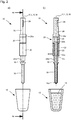
- the soft magnetic tip 16 when the soft magnetic tip 16 is magnetized, the magnetic particles in the suspension 14 are deposited on the immersion end 16a of the tip 16 when it is immersed in the suspension 14. This allows the magnetic particles and substances adhering to their outside from the suspension 14 are removed.
- the embodiment shown allows a radially extremely slim design, which allows the integration of the magnetic separation device shown in a pipetting device, in particular in a pipetting head, wherein the magnetic separation device can then replace a pipetting channel in the pipetting device.
Landscapes
- Apparatus Associated With Microorganisms And Enzymes (AREA)
- Electromagnets (AREA)
- Physical Or Chemical Processes And Apparatus (AREA)
Claims (11)
- Dispositif de séparation magnétique (10) pour séparer des particules magnétiques d'une suspension (14) avec une pointe magnétique douce (16) dont l'état de magnétisation peut être changé sélectivement entre un état plus fortement magnétisé et un état moins fortement magnétisé, ladite pointe (16) comprenant une extrémité d'immersion (16a) pour l'introduction dans ladite suspension (14) et une section de magnétisation (16b) pour changer l'état de magnétisation de ladite pointe (16), ledit dispositif de séparation (10) comprenant un premier agencement d'aimants (22), dont le champ magnétique dans la section de magnétisation (16b) de la pointe (16) est variable dans le temps pour changer son état de magnétisation, dans lequel le premier agencement d'aimants (22) comprend au moins un aimant permanent comme agencement d'aimants de magnétisation (22), et est déplaçable par rapport à la pointe (16) entre une position de non-magnétisation plus éloignée de la pointe (16) et séparée de celle-ci par un entrefer, et une position de magnétisation plus rapprochée de la pointe (16),
caractérisé en ce que le dispositif de séparation (10) comprend un deuxième agencement d'aimants (30), dans lequel le premier (22) et le deuxième agencement d'aimants (30) sont déplaçables l'un par rapport à l'autre et l'état de magnétisation de la pointe magnétique douce (16) dépend de la position relative des deux agencements d'aimants (22, 30), dans lequel le deuxième agencement d'aimants (30) présente comme agencement d'aimants d'entraînement (30) une bobine électrique qui peut être alimentée en courant de manière sélective, qui, en fonction de son alimentation en courant, déplace l'agencement d'aimants de magnétisation (22) de la position de magnétisation à la position de non-magnétisation, le dispositif de séparation magnétique (10) comprenant un dispositif de maintien (26a), qui maintient l'agencement d'aimants de magnétisation (22) dans la position de non-magnétisation, le dispositif de maintien (26a) comprenant un élément de maintien ferromagnétique (26a) avec lequel l'agencement d'aimants de magnétisation (22) est en contact magnétique dans la position de non-magnétisation, dans lequel l'agencement d'aimants d'entraînement (30) est stationnaire par rapport à la pointe magnétique douce (16), et en ce que la bobine électrique à être sélectivement alimentée en courant de l'agencement d'aimants d'entraînement (30) déplace également l'agencement d'aimants de magnétisation (22) de la position de non-magnétisation à la position de magnétisation, en fonction de son alimentation en courant. - Dispositif de séparation magnétique (10) selon la revendication 1, caractérisé en ce que l'agencement d'aimants de magnétisation (22) est au moins un aimant permanent ou un agencement d'aimants permanents avec plusieurs aimants permanents.
- Dispositif de séparation magnétique (10) selon la revendication 2, caractérisé en ce que l'agencement d'aimants de magnétisation (22) est en contact magnétique avec la pointe (16) en position de magnétisation.
- Dispositif de séparation magnétique (10) selon l'une des revendications précédentes,
caractérisé en ce que l'élément de maintien (26a) est un élément de maintien magnétique doux (26a). - Dispositif de séparation magnétique (10) selon l'une des revendications précédentes,
caractérisé en ce que la pointe magnétique douce (16) s'étend le long d'un axe de pointe (L), et est de préférence au moins par sections symétrique en rotation par rapport à l'axe de pointe (L) comme axe de symétrie de rotation (M), un trajet de déplacement relatif (V) des deux agencements d'aimants (22, 30) étant parallèle, de préférence colinéaire, à l'axe de pointe (L). - Dispositif de séparation magnétique (10) selon l'une des revendications précédentes,
caractérisé en ce qu'un agencement d'aimants (30) entoure l'autre (22), de préférence coaxialement. - Dispositif de séparation magnétique (10) selon l'une des revendications précédentes, y compris la revendication 5,
caractérisé en ce qu'au moins un aimant permanent de l'agencement d'aimants de magnétisation (22) est coaxial à l'axe de pointe (L) et est polarisé le long de cet axe (L). - Dispositif de séparation magnétique (10) selon la revendication 7, caractérisé en ce qu'au moins un aimant permanent de l'agencement d'aimants de magnétisation (22) est symétrique en rotation par rapport à l'axe de pointe (L) comme axe de symétrie de rotation (M).
- Dispositif de séparation magnétique (10) selon l'une des revendications précédentes,
caractérisé en ce que la pointe magnétique douce (16) s'étend le long d'un axe de pointe (L), le dispositif de séparation (10) présentant un entraînement rotatif au moyen duquel la pointe (16) peut être tournée autour de son axe de pointe (L). - Dispositif de pipetage avec au moins un dispositif de séparation magnétique (10) selon l'une des revendications 1 à 9 au lieu d'un canal de pipetage.
- Dispositif de manipulation de liquide avec une pluralité de dispositifs de séparation magnétiques (10) selon la revendication 9, la pluralité de dispositifs de séparation magnétiques (10) étant prévus avec des axes de pointe (L) parallèles, disposés en forme de grille, chaque dispositif de séparation (10) présentant son propre entraînement rotatif pour faire tourner la pointe (16) respective autour de son axe de pointe (L), chaque entraînement rotatif pouvant être opéré séparément des entraînements rotatifs des autres dispositifs de séparation (10).
Priority Applications (1)
| Application Number | Priority Date | Filing Date | Title |
|---|---|---|---|
| EP18204538.5A EP3461560B1 (fr) | 2015-09-18 | 2016-09-15 | Dispositif de séparation magnétique à activation et désactivation magnétiques |
Applications Claiming Priority (2)
| Application Number | Priority Date | Filing Date | Title |
|---|---|---|---|
| DE102015218010.7A DE102015218010A1 (de) | 2015-09-18 | 2015-09-18 | Magnetische Trennvorrichtung mit magnetischer Aktivierung und Deaktivierung |
| PCT/EP2016/071804 WO2017046234A1 (fr) | 2015-09-18 | 2016-09-15 | Dispositif de séparation magnétique à activation et désactivation magnétique |
Related Child Applications (2)
| Application Number | Title | Priority Date | Filing Date |
|---|---|---|---|
| EP18204538.5A Division EP3461560B1 (fr) | 2015-09-18 | 2016-09-15 | Dispositif de séparation magnétique à activation et désactivation magnétiques |
| EP18204538.5A Division-Into EP3461560B1 (fr) | 2015-09-18 | 2016-09-15 | Dispositif de séparation magnétique à activation et désactivation magnétiques |
Publications (2)
| Publication Number | Publication Date |
|---|---|
| EP3349909A1 EP3349909A1 (fr) | 2018-07-25 |
| EP3349909B1 true EP3349909B1 (fr) | 2020-05-06 |
Family
ID=56943527
Family Applications (2)
| Application Number | Title | Priority Date | Filing Date |
|---|---|---|---|
| EP16766940.7A Active EP3349909B1 (fr) | 2015-09-18 | 2016-09-15 | Dispositif de séparation magnétique à activation et désactivation magnétique |
| EP18204538.5A Active EP3461560B1 (fr) | 2015-09-18 | 2016-09-15 | Dispositif de séparation magnétique à activation et désactivation magnétiques |
Family Applications After (1)
| Application Number | Title | Priority Date | Filing Date |
|---|---|---|---|
| EP18204538.5A Active EP3461560B1 (fr) | 2015-09-18 | 2016-09-15 | Dispositif de séparation magnétique à activation et désactivation magnétiques |
Country Status (3)
| Country | Link |
|---|---|
| EP (2) | EP3349909B1 (fr) |
| DE (1) | DE102015218010A1 (fr) |
| WO (1) | WO2017046234A1 (fr) |
Families Citing this family (3)
| Publication number | Priority date | Publication date | Assignee | Title |
|---|---|---|---|---|
| EP3147028B1 (fr) * | 2015-09-25 | 2019-06-19 | Constantin Odefey | Procede et dispositif de separation magnetique de nanobilles |
| WO2018049483A1 (fr) | 2016-09-16 | 2018-03-22 | The University Of Western Australia | Outil magnétique et procédé de collecte de particules magnétiques utilisant celui-ci |
| DE102016219053A1 (de) | 2016-09-30 | 2018-04-05 | Hamilton Bonaduz Ag | Magnetische Trennvorrichtung mit unkörperlicher Kopplung zwischen Magnetanordnung und deren Bewegungsantrieb |
Family Cites Families (13)
| Publication number | Priority date | Publication date | Assignee | Title |
|---|---|---|---|---|
| US2693979A (en) * | 1950-08-03 | 1954-11-09 | George L Russell | Magnetic device |
| FR2554016B1 (fr) | 1983-10-27 | 1986-08-08 | Pasteur Institut | Perfectionnements apportes aux moyens magnetiques destines a retirer des billes de gel magnetique d'un fluide de dosage |
| FR2572178B1 (fr) | 1984-10-23 | 1988-10-28 | Pasteur Institut | Nouveau dispositif magnetique destine a retirer des billes de gel magnetique d'un milieu a analyser et a les transferer sur un milieu de dosage immunoenzymatique |
| FI932866A0 (fi) | 1993-06-21 | 1993-06-21 | Labsystems Oy | Separeringsfoerfarande |
| US5567326A (en) | 1994-09-19 | 1996-10-22 | Promega Corporation | Multisample magnetic separation device |
| IL123210A0 (en) * | 1998-02-06 | 1998-09-24 | Gombinsky Moshe | A device and system for the collection of magnetic particles |
| DE10057396C1 (de) | 2000-11-18 | 2002-04-04 | Karlsruhe Forschzent | Verfahren zum Abtrennen eines dispergierten oder gelösten Stoffes und Magnetseparator |
| FI120863B (fi) * | 2002-10-18 | 2010-04-15 | Biocontrol Systems Inc | Magneettinen siirtomenetelmä ja mikropartikkelien siirtolaite |
| DE10331254B4 (de) | 2003-07-10 | 2006-05-04 | Chemagen Biopolymer-Technologie Aktiengesellschaft | Vorrichtung und Verfahren zum Abtrennen von magnetischen oder magnetisierbaren Partikeln aus einer Flüssigkeit |
| DE102005004664B4 (de) | 2005-02-02 | 2007-06-21 | Chemagen Biopolymer-Technologie Aktiengesellschaft | Vorrichtung und Verfahren und Verwendung zum Abtrennen von magnetischen oder magnetisierbaren Partikeln aus einer Flüssigkeit sowie deren Verwendungen |
| US7534081B2 (en) * | 2005-05-24 | 2009-05-19 | Festo Corporation | Apparatus and method for transferring samples from a source to a target |
| US7799281B2 (en) * | 2007-01-16 | 2010-09-21 | Festo Corporation | Flux concentrator for biomagnetic particle transfer device |
| JP2011511273A (ja) * | 2008-01-25 | 2011-04-07 | ルミネックス コーポレーション | ソレノイド・アクチュエータ |
-
2015
- 2015-09-18 DE DE102015218010.7A patent/DE102015218010A1/de not_active Withdrawn
-
2016
- 2016-09-15 EP EP16766940.7A patent/EP3349909B1/fr active Active
- 2016-09-15 WO PCT/EP2016/071804 patent/WO2017046234A1/fr not_active Ceased
- 2016-09-15 EP EP18204538.5A patent/EP3461560B1/fr active Active
Non-Patent Citations (1)
| Title |
|---|
| None * |
Also Published As
| Publication number | Publication date |
|---|---|
| EP3461560B1 (fr) | 2020-04-29 |
| WO2017046234A1 (fr) | 2017-03-23 |
| EP3461560A1 (fr) | 2019-04-03 |
| DE102015218010A1 (de) | 2017-03-23 |
| EP3349909A1 (fr) | 2018-07-25 |
Similar Documents
| Publication | Publication Date | Title |
|---|---|---|
| EP0406782B1 (fr) | Dispositif de retenue électro-magnétique | |
| EP2973618B1 (fr) | Dispositif de réglage électromagnétique | |
| DE102011014192B4 (de) | Elektromagnetische Aktuatorvorrichtung | |
| EP3349909B1 (fr) | Dispositif de séparation magnétique à activation et désactivation magnétique | |
| DE102012107922A1 (de) | Elektromagnetische Aktuatorvorrichtung | |
| EP2474009B1 (fr) | Dispositif d'actionnement électromagnétique bistable | |
| DE602004007646T3 (de) | Elektromagnetischer antrieb | |
| EP4128291B1 (fr) | Actionneur electromagnetique et son utilisation | |
| DE102013102276B4 (de) | Verdrehschutz | |
| DE202016107420U1 (de) | Vorrichtung zum Herstellen von Bremskraft- oder Antriebskraft-Übertragungen | |
| DE102017211257B4 (de) | Elektromagnetischer Antrieb und damit ausgestattetes Ventil | |
| EP3349910B1 (fr) | Dispositif de séparation magnétique à activation et désactivation mécanique | |
| DE10313144B3 (de) | Magnetischer Linearantrieb | |
| DE10153002B4 (de) | Drehsteller mit Hubmagnet, sowie Hubmagnet | |
| DE2460121A1 (de) | Haltebremse | |
| DE102005005805B3 (de) | Greifvorrichtung | |
| DE9011582U1 (de) | Elektromagnetische Bremseinrichtung | |
| DE19832694C2 (de) | Polreibungsbremse | |
| EP2624421B1 (fr) | Axe linéaire avec entraînement électrique et fixation de fin sans courant | |
| DE102022116459A1 (de) | Bistabiler aktuator mit mittenjoch | |
| DE102015103169A1 (de) | Stellvorrichtung mit eingehängten Stößeln | |
| DE29801860U1 (de) | Elektromagnet | |
| DE10357001B4 (de) | Magnetischer Linearantrieb | |
| DD271406A5 (de) | Verfahren und vorrichtung zum umwandeln von stationaer magnetischer energie in mechanische energie | |
| DE102015007705A1 (de) | Elektromagnetischer Aktuator und Verfahren zum Betrieb des Aktuators |
Legal Events
| Date | Code | Title | Description |
|---|---|---|---|
| STAA | Information on the status of an ep patent application or granted ep patent |
Free format text: STATUS: THE INTERNATIONAL PUBLICATION HAS BEEN MADE |
|
| PUAI | Public reference made under article 153(3) epc to a published international application that has entered the european phase |
Free format text: ORIGINAL CODE: 0009012 |
|
| STAA | Information on the status of an ep patent application or granted ep patent |
Free format text: STATUS: REQUEST FOR EXAMINATION WAS MADE |
|
| 17P | Request for examination filed |
Effective date: 20180416 |
|
| AK | Designated contracting states |
Kind code of ref document: A1 Designated state(s): AL AT BE BG CH CY CZ DE DK EE ES FI FR GB GR HR HU IE IS IT LI LT LU LV MC MK MT NL NO PL PT RO RS SE SI SK SM TR |
|
| AX | Request for extension of the european patent |
Extension state: BA ME |
|
| DAV | Request for validation of the european patent (deleted) | ||
| DAX | Request for extension of the european patent (deleted) | ||
| GRAP | Despatch of communication of intention to grant a patent |
Free format text: ORIGINAL CODE: EPIDOSNIGR1 |
|
| STAA | Information on the status of an ep patent application or granted ep patent |
Free format text: STATUS: GRANT OF PATENT IS INTENDED |
|
| INTG | Intention to grant announced |
Effective date: 20191114 |
|
| GRAJ | Information related to disapproval of communication of intention to grant by the applicant or resumption of examination proceedings by the epo deleted |
Free format text: ORIGINAL CODE: EPIDOSDIGR1 |
|
| STAA | Information on the status of an ep patent application or granted ep patent |
Free format text: STATUS: REQUEST FOR EXAMINATION WAS MADE |
|
| GRAR | Information related to intention to grant a patent recorded |
Free format text: ORIGINAL CODE: EPIDOSNIGR71 |
|
| GRAS | Grant fee paid |
Free format text: ORIGINAL CODE: EPIDOSNIGR3 |
|
| STAA | Information on the status of an ep patent application or granted ep patent |
Free format text: STATUS: GRANT OF PATENT IS INTENDED |
|
| GRAA | (expected) grant |
Free format text: ORIGINAL CODE: 0009210 |
|
| STAA | Information on the status of an ep patent application or granted ep patent |
Free format text: STATUS: THE PATENT HAS BEEN GRANTED |
|
| INTC | Intention to grant announced (deleted) | ||
| AK | Designated contracting states |
Kind code of ref document: B1 Designated state(s): AL AT BE BG CH CY CZ DE DK EE ES FI FR GB GR HR HU IE IS IT LI LT LU LV MC MK MT NL NO PL PT RO RS SE SI SK SM TR |
|
| INTG | Intention to grant announced |
Effective date: 20200327 |
|
| REG | Reference to a national code |
Ref country code: GB Ref legal event code: FG4D Free format text: NOT ENGLISH |
|
| REG | Reference to a national code |
Ref country code: CH Ref legal event code: EP Ref country code: AT Ref legal event code: REF Ref document number: 1265934 Country of ref document: AT Kind code of ref document: T Effective date: 20200515 |
|
| REG | Reference to a national code |
Ref country code: IE Ref legal event code: FG4D Free format text: LANGUAGE OF EP DOCUMENT: GERMAN |
|
| REG | Reference to a national code |
Ref country code: DE Ref legal event code: R096 Ref document number: 502016009883 Country of ref document: DE |
|
| REG | Reference to a national code |
Ref country code: CH Ref legal event code: NV Representative=s name: E. BLUM AND CO. AG PATENT- UND MARKENANWAELTE , CH |
|
| REG | Reference to a national code |
Ref country code: LT Ref legal event code: MG4D |
|
| REG | Reference to a national code |
Ref country code: NL Ref legal event code: MP Effective date: 20200506 |
|
| PG25 | Lapsed in a contracting state [announced via postgrant information from national office to epo] |
Ref country code: FI Free format text: LAPSE BECAUSE OF FAILURE TO SUBMIT A TRANSLATION OF THE DESCRIPTION OR TO PAY THE FEE WITHIN THE PRESCRIBED TIME-LIMIT Effective date: 20200506 Ref country code: PT Free format text: LAPSE BECAUSE OF FAILURE TO SUBMIT A TRANSLATION OF THE DESCRIPTION OR TO PAY THE FEE WITHIN THE PRESCRIBED TIME-LIMIT Effective date: 20200907 Ref country code: IS Free format text: LAPSE BECAUSE OF FAILURE TO SUBMIT A TRANSLATION OF THE DESCRIPTION OR TO PAY THE FEE WITHIN THE PRESCRIBED TIME-LIMIT Effective date: 20200906 Ref country code: SE Free format text: LAPSE BECAUSE OF FAILURE TO SUBMIT A TRANSLATION OF THE DESCRIPTION OR TO PAY THE FEE WITHIN THE PRESCRIBED TIME-LIMIT Effective date: 20200506 Ref country code: NO Free format text: LAPSE BECAUSE OF FAILURE TO SUBMIT A TRANSLATION OF THE DESCRIPTION OR TO PAY THE FEE WITHIN THE PRESCRIBED TIME-LIMIT Effective date: 20200806 Ref country code: GR Free format text: LAPSE BECAUSE OF FAILURE TO SUBMIT A TRANSLATION OF THE DESCRIPTION OR TO PAY THE FEE WITHIN THE PRESCRIBED TIME-LIMIT Effective date: 20200807 Ref country code: LT Free format text: LAPSE BECAUSE OF FAILURE TO SUBMIT A TRANSLATION OF THE DESCRIPTION OR TO PAY THE FEE WITHIN THE PRESCRIBED TIME-LIMIT Effective date: 20200506 |
|
| PG25 | Lapsed in a contracting state [announced via postgrant information from national office to epo] |
Ref country code: BG Free format text: LAPSE BECAUSE OF FAILURE TO SUBMIT A TRANSLATION OF THE DESCRIPTION OR TO PAY THE FEE WITHIN THE PRESCRIBED TIME-LIMIT Effective date: 20200806 Ref country code: RS Free format text: LAPSE BECAUSE OF FAILURE TO SUBMIT A TRANSLATION OF THE DESCRIPTION OR TO PAY THE FEE WITHIN THE PRESCRIBED TIME-LIMIT Effective date: 20200506 Ref country code: HR Free format text: LAPSE BECAUSE OF FAILURE TO SUBMIT A TRANSLATION OF THE DESCRIPTION OR TO PAY THE FEE WITHIN THE PRESCRIBED TIME-LIMIT Effective date: 20200506 Ref country code: LV Free format text: LAPSE BECAUSE OF FAILURE TO SUBMIT A TRANSLATION OF THE DESCRIPTION OR TO PAY THE FEE WITHIN THE PRESCRIBED TIME-LIMIT Effective date: 20200506 |
|
| PG25 | Lapsed in a contracting state [announced via postgrant information from national office to epo] |
Ref country code: NL Free format text: LAPSE BECAUSE OF FAILURE TO SUBMIT A TRANSLATION OF THE DESCRIPTION OR TO PAY THE FEE WITHIN THE PRESCRIBED TIME-LIMIT Effective date: 20200506 Ref country code: AL Free format text: LAPSE BECAUSE OF FAILURE TO SUBMIT A TRANSLATION OF THE DESCRIPTION OR TO PAY THE FEE WITHIN THE PRESCRIBED TIME-LIMIT Effective date: 20200506 |
|
| PG25 | Lapsed in a contracting state [announced via postgrant information from national office to epo] |
Ref country code: ES Free format text: LAPSE BECAUSE OF FAILURE TO SUBMIT A TRANSLATION OF THE DESCRIPTION OR TO PAY THE FEE WITHIN THE PRESCRIBED TIME-LIMIT Effective date: 20200506 Ref country code: DK Free format text: LAPSE BECAUSE OF FAILURE TO SUBMIT A TRANSLATION OF THE DESCRIPTION OR TO PAY THE FEE WITHIN THE PRESCRIBED TIME-LIMIT Effective date: 20200506 Ref country code: IT Free format text: LAPSE BECAUSE OF FAILURE TO SUBMIT A TRANSLATION OF THE DESCRIPTION OR TO PAY THE FEE WITHIN THE PRESCRIBED TIME-LIMIT Effective date: 20200506 Ref country code: SM Free format text: LAPSE BECAUSE OF FAILURE TO SUBMIT A TRANSLATION OF THE DESCRIPTION OR TO PAY THE FEE WITHIN THE PRESCRIBED TIME-LIMIT Effective date: 20200506 Ref country code: CZ Free format text: LAPSE BECAUSE OF FAILURE TO SUBMIT A TRANSLATION OF THE DESCRIPTION OR TO PAY THE FEE WITHIN THE PRESCRIBED TIME-LIMIT Effective date: 20200506 Ref country code: EE Free format text: LAPSE BECAUSE OF FAILURE TO SUBMIT A TRANSLATION OF THE DESCRIPTION OR TO PAY THE FEE WITHIN THE PRESCRIBED TIME-LIMIT Effective date: 20200506 Ref country code: RO Free format text: LAPSE BECAUSE OF FAILURE TO SUBMIT A TRANSLATION OF THE DESCRIPTION OR TO PAY THE FEE WITHIN THE PRESCRIBED TIME-LIMIT Effective date: 20200506 |
|
| REG | Reference to a national code |
Ref country code: DE Ref legal event code: R097 Ref document number: 502016009883 Country of ref document: DE |
|
| PG25 | Lapsed in a contracting state [announced via postgrant information from national office to epo] |
Ref country code: PL Free format text: LAPSE BECAUSE OF FAILURE TO SUBMIT A TRANSLATION OF THE DESCRIPTION OR TO PAY THE FEE WITHIN THE PRESCRIBED TIME-LIMIT Effective date: 20200506 Ref country code: SK Free format text: LAPSE BECAUSE OF FAILURE TO SUBMIT A TRANSLATION OF THE DESCRIPTION OR TO PAY THE FEE WITHIN THE PRESCRIBED TIME-LIMIT Effective date: 20200506 |
|
| PLBE | No opposition filed within time limit |
Free format text: ORIGINAL CODE: 0009261 |
|
| STAA | Information on the status of an ep patent application or granted ep patent |
Free format text: STATUS: NO OPPOSITION FILED WITHIN TIME LIMIT |
|
| 26N | No opposition filed |
Effective date: 20210209 |
|
| GBPC | Gb: european patent ceased through non-payment of renewal fee |
Effective date: 20200915 |
|
| PG25 | Lapsed in a contracting state [announced via postgrant information from national office to epo] |
Ref country code: SI Free format text: LAPSE BECAUSE OF FAILURE TO SUBMIT A TRANSLATION OF THE DESCRIPTION OR TO PAY THE FEE WITHIN THE PRESCRIBED TIME-LIMIT Effective date: 20200506 |
|
| REG | Reference to a national code |
Ref country code: BE Ref legal event code: MM Effective date: 20200930 |
|
| PG25 | Lapsed in a contracting state [announced via postgrant information from national office to epo] |
Ref country code: LU Free format text: LAPSE BECAUSE OF NON-PAYMENT OF DUE FEES Effective date: 20200915 |
|
| PG25 | Lapsed in a contracting state [announced via postgrant information from national office to epo] |
Ref country code: FR Free format text: LAPSE BECAUSE OF NON-PAYMENT OF DUE FEES Effective date: 20200930 |
|
| PG25 | Lapsed in a contracting state [announced via postgrant information from national office to epo] |
Ref country code: IE Free format text: LAPSE BECAUSE OF NON-PAYMENT OF DUE FEES Effective date: 20200915 Ref country code: GB Free format text: LAPSE BECAUSE OF NON-PAYMENT OF DUE FEES Effective date: 20200915 Ref country code: BE Free format text: LAPSE BECAUSE OF NON-PAYMENT OF DUE FEES Effective date: 20200930 |
|
| PG25 | Lapsed in a contracting state [announced via postgrant information from national office to epo] |
Ref country code: TR Free format text: LAPSE BECAUSE OF FAILURE TO SUBMIT A TRANSLATION OF THE DESCRIPTION OR TO PAY THE FEE WITHIN THE PRESCRIBED TIME-LIMIT Effective date: 20200506 Ref country code: MT Free format text: LAPSE BECAUSE OF FAILURE TO SUBMIT A TRANSLATION OF THE DESCRIPTION OR TO PAY THE FEE WITHIN THE PRESCRIBED TIME-LIMIT Effective date: 20200506 Ref country code: CY Free format text: LAPSE BECAUSE OF FAILURE TO SUBMIT A TRANSLATION OF THE DESCRIPTION OR TO PAY THE FEE WITHIN THE PRESCRIBED TIME-LIMIT Effective date: 20200506 |
|
| PG25 | Lapsed in a contracting state [announced via postgrant information from national office to epo] |
Ref country code: MK Free format text: LAPSE BECAUSE OF FAILURE TO SUBMIT A TRANSLATION OF THE DESCRIPTION OR TO PAY THE FEE WITHIN THE PRESCRIBED TIME-LIMIT Effective date: 20200506 Ref country code: MC Free format text: LAPSE BECAUSE OF FAILURE TO SUBMIT A TRANSLATION OF THE DESCRIPTION OR TO PAY THE FEE WITHIN THE PRESCRIBED TIME-LIMIT Effective date: 20200506 |
|
| PGFP | Annual fee paid to national office [announced via postgrant information from national office to epo] |
Ref country code: DE Payment date: 20220818 Year of fee payment: 7 |
|
| REG | Reference to a national code |
Ref country code: AT Ref legal event code: MM01 Ref document number: 1265934 Country of ref document: AT Kind code of ref document: T Effective date: 20210915 |
|
| PG25 | Lapsed in a contracting state [announced via postgrant information from national office to epo] |
Ref country code: AT Free format text: LAPSE BECAUSE OF NON-PAYMENT OF DUE FEES Effective date: 20210915 |
|
| PGFP | Annual fee paid to national office [announced via postgrant information from national office to epo] |
Ref country code: CH Payment date: 20221001 Year of fee payment: 7 |
|
| P01 | Opt-out of the competence of the unified patent court (upc) registered |
Effective date: 20230521 |
|
| REG | Reference to a national code |
Ref country code: DE Ref legal event code: R119 Ref document number: 502016009883 Country of ref document: DE |
|
| REG | Reference to a national code |
Ref country code: CH Ref legal event code: PL |
|
| PG25 | Lapsed in a contracting state [announced via postgrant information from national office to epo] |
Ref country code: CH Free format text: LAPSE BECAUSE OF NON-PAYMENT OF DUE FEES Effective date: 20230930 |
|
| PG25 | Lapsed in a contracting state [announced via postgrant information from national office to epo] |
Ref country code: DE Free format text: LAPSE BECAUSE OF NON-PAYMENT OF DUE FEES Effective date: 20240403 Ref country code: CH Free format text: LAPSE BECAUSE OF NON-PAYMENT OF DUE FEES Effective date: 20230930 |