EP3461560A1 - Dispositif de séparation magnétique à activation et désactivation magnétiques - Google Patents
Dispositif de séparation magnétique à activation et désactivation magnétiques Download PDFInfo
- Publication number
- EP3461560A1 EP3461560A1 EP18204538.5A EP18204538A EP3461560A1 EP 3461560 A1 EP3461560 A1 EP 3461560A1 EP 18204538 A EP18204538 A EP 18204538A EP 3461560 A1 EP3461560 A1 EP 3461560A1
- Authority
- EP
- European Patent Office
- Prior art keywords
- magnetization
- tip
- magnet
- magnetic
- magnet assembly
- Prior art date
- Legal status (The legal status is an assumption and is not a legal conclusion. Google has not performed a legal analysis and makes no representation as to the accuracy of the status listed.)
- Granted
Links
- 230000005291 magnetic effect Effects 0.000 title claims abstract description 196
- 238000007885 magnetic separation Methods 0.000 title claims abstract description 47
- 230000004913 activation Effects 0.000 title 1
- 230000009849 deactivation Effects 0.000 title 1
- 230000005415 magnetization Effects 0.000 claims abstract description 219
- 239000000725 suspension Substances 0.000 claims abstract description 42
- 238000000926 separation method Methods 0.000 claims abstract description 20
- 239000006249 magnetic particle Substances 0.000 claims abstract description 19
- 230000008859 change Effects 0.000 claims abstract description 13
- 238000000429 assembly Methods 0.000 claims abstract description 12
- 230000000712 assembly Effects 0.000 claims abstract description 12
- 239000006148 magnetic separator Substances 0.000 claims description 15
- 238000006073 displacement reaction Methods 0.000 claims description 14
- 239000007788 liquid Substances 0.000 claims description 6
- 238000004804 winding Methods 0.000 claims description 2
- 238000007654 immersion Methods 0.000 abstract description 9
- 230000001419 dependent effect Effects 0.000 abstract 1
- 239000000696 magnetic material Substances 0.000 description 12
- 230000005484 gravity Effects 0.000 description 11
- 230000008878 coupling Effects 0.000 description 5
- 238000010168 coupling process Methods 0.000 description 5
- 238000005859 coupling reaction Methods 0.000 description 5
- 238000013461 design Methods 0.000 description 5
- 239000003302 ferromagnetic material Substances 0.000 description 5
- 239000000463 material Substances 0.000 description 5
- 230000009471 action Effects 0.000 description 4
- 230000000694 effects Effects 0.000 description 4
- 238000003780 insertion Methods 0.000 description 4
- 230000037431 insertion Effects 0.000 description 4
- 238000013459 approach Methods 0.000 description 3
- 239000011248 coating agent Substances 0.000 description 3
- 238000000576 coating method Methods 0.000 description 3
- 238000005520 cutting process Methods 0.000 description 3
- 230000005294 ferromagnetic effect Effects 0.000 description 3
- 239000002245 particle Substances 0.000 description 3
- 239000000126 substance Substances 0.000 description 3
- 230000008646 thermal stress Effects 0.000 description 3
- XEEYBQQBJWHFJM-UHFFFAOYSA-N Iron Chemical group [Fe] XEEYBQQBJWHFJM-UHFFFAOYSA-N 0.000 description 2
- 230000015572 biosynthetic process Effects 0.000 description 2
- 238000010276 construction Methods 0.000 description 2
- 238000000151 deposition Methods 0.000 description 2
- 238000000034 method Methods 0.000 description 2
- 230000036316 preload Effects 0.000 description 2
- 230000008569 process Effects 0.000 description 2
- 230000001681 protective effect Effects 0.000 description 2
- 229910001369 Brass Inorganic materials 0.000 description 1
- XAGFODPZIPBFFR-UHFFFAOYSA-N aluminium Chemical compound [Al] XAGFODPZIPBFFR-UHFFFAOYSA-N 0.000 description 1
- 229910052782 aluminium Inorganic materials 0.000 description 1
- 239000012620 biological material Substances 0.000 description 1
- 239000010951 brass Substances 0.000 description 1
- 238000004140 cleaning Methods 0.000 description 1
- 239000000470 constituent Substances 0.000 description 1
- 230000008021 deposition Effects 0.000 description 1
- 238000011161 development Methods 0.000 description 1
- 230000004907 flux Effects 0.000 description 1
- 238000010438 heat treatment Methods 0.000 description 1
- 239000004615 ingredient Substances 0.000 description 1
- 238000009434 installation Methods 0.000 description 1
- 230000010354 integration Effects 0.000 description 1
- 239000011159 matrix material Substances 0.000 description 1
- 230000010287 polarization Effects 0.000 description 1
- 238000000746 purification Methods 0.000 description 1
- 238000004904 shortening Methods 0.000 description 1
- 230000001052 transient effect Effects 0.000 description 1
- 230000007704 transition Effects 0.000 description 1
- 230000003313 weakening effect Effects 0.000 description 1
Images



Classifications
-
- B—PERFORMING OPERATIONS; TRANSPORTING
- B03—SEPARATION OF SOLID MATERIALS USING LIQUIDS OR USING PNEUMATIC TABLES OR JIGS; MAGNETIC OR ELECTROSTATIC SEPARATION OF SOLID MATERIALS FROM SOLID MATERIALS OR FLUIDS; SEPARATION BY HIGH-VOLTAGE ELECTRIC FIELDS
- B03C—MAGNETIC OR ELECTROSTATIC SEPARATION OF SOLID MATERIALS FROM SOLID MATERIALS OR FLUIDS; SEPARATION BY HIGH-VOLTAGE ELECTRIC FIELDS
- B03C1/00—Magnetic separation
- B03C1/02—Magnetic separation acting directly on the substance being separated
- B03C1/025—High gradient magnetic separators
- B03C1/031—Component parts; Auxiliary operations
- B03C1/033—Component parts; Auxiliary operations characterised by the magnetic circuit
- B03C1/0332—Component parts; Auxiliary operations characterised by the magnetic circuit using permanent magnets
-
- B—PERFORMING OPERATIONS; TRANSPORTING
- B03—SEPARATION OF SOLID MATERIALS USING LIQUIDS OR USING PNEUMATIC TABLES OR JIGS; MAGNETIC OR ELECTROSTATIC SEPARATION OF SOLID MATERIALS FROM SOLID MATERIALS OR FLUIDS; SEPARATION BY HIGH-VOLTAGE ELECTRIC FIELDS
- B03C—MAGNETIC OR ELECTROSTATIC SEPARATION OF SOLID MATERIALS FROM SOLID MATERIALS OR FLUIDS; SEPARATION BY HIGH-VOLTAGE ELECTRIC FIELDS
- B03C1/00—Magnetic separation
- B03C1/02—Magnetic separation acting directly on the substance being separated
- B03C1/025—High gradient magnetic separators
- B03C1/031—Component parts; Auxiliary operations
- B03C1/033—Component parts; Auxiliary operations characterised by the magnetic circuit
- B03C1/034—Component parts; Auxiliary operations characterised by the magnetic circuit characterised by the matrix elements
-
- B—PERFORMING OPERATIONS; TRANSPORTING
- B03—SEPARATION OF SOLID MATERIALS USING LIQUIDS OR USING PNEUMATIC TABLES OR JIGS; MAGNETIC OR ELECTROSTATIC SEPARATION OF SOLID MATERIALS FROM SOLID MATERIALS OR FLUIDS; SEPARATION BY HIGH-VOLTAGE ELECTRIC FIELDS
- B03C—MAGNETIC OR ELECTROSTATIC SEPARATION OF SOLID MATERIALS FROM SOLID MATERIALS OR FLUIDS; SEPARATION BY HIGH-VOLTAGE ELECTRIC FIELDS
- B03C1/00—Magnetic separation
- B03C1/02—Magnetic separation acting directly on the substance being separated
- B03C1/28—Magnetic plugs and dipsticks
- B03C1/284—Magnetic plugs and dipsticks with associated cleaning means, e.g. retractable non-magnetic sleeve
-
- B—PERFORMING OPERATIONS; TRANSPORTING
- B03—SEPARATION OF SOLID MATERIALS USING LIQUIDS OR USING PNEUMATIC TABLES OR JIGS; MAGNETIC OR ELECTROSTATIC SEPARATION OF SOLID MATERIALS FROM SOLID MATERIALS OR FLUIDS; SEPARATION BY HIGH-VOLTAGE ELECTRIC FIELDS
- B03C—MAGNETIC OR ELECTROSTATIC SEPARATION OF SOLID MATERIALS FROM SOLID MATERIALS OR FLUIDS; SEPARATION BY HIGH-VOLTAGE ELECTRIC FIELDS
- B03C1/00—Magnetic separation
- B03C1/02—Magnetic separation acting directly on the substance being separated
- B03C1/28—Magnetic plugs and dipsticks
- B03C1/286—Magnetic plugs and dipsticks disposed at the inner circumference of a recipient, e.g. magnetic drain bolt
-
- B—PERFORMING OPERATIONS; TRANSPORTING
- B03—SEPARATION OF SOLID MATERIALS USING LIQUIDS OR USING PNEUMATIC TABLES OR JIGS; MAGNETIC OR ELECTROSTATIC SEPARATION OF SOLID MATERIALS FROM SOLID MATERIALS OR FLUIDS; SEPARATION BY HIGH-VOLTAGE ELECTRIC FIELDS
- B03C—MAGNETIC OR ELECTROSTATIC SEPARATION OF SOLID MATERIALS FROM SOLID MATERIALS OR FLUIDS; SEPARATION BY HIGH-VOLTAGE ELECTRIC FIELDS
- B03C2201/00—Details of magnetic or electrostatic separation
- B03C2201/18—Magnetic separation whereby the particles are suspended in a liquid
-
- B—PERFORMING OPERATIONS; TRANSPORTING
- B03—SEPARATION OF SOLID MATERIALS USING LIQUIDS OR USING PNEUMATIC TABLES OR JIGS; MAGNETIC OR ELECTROSTATIC SEPARATION OF SOLID MATERIALS FROM SOLID MATERIALS OR FLUIDS; SEPARATION BY HIGH-VOLTAGE ELECTRIC FIELDS
- B03C—MAGNETIC OR ELECTROSTATIC SEPARATION OF SOLID MATERIALS FROM SOLID MATERIALS OR FLUIDS; SEPARATION BY HIGH-VOLTAGE ELECTRIC FIELDS
- B03C2201/00—Details of magnetic or electrostatic separation
- B03C2201/26—Details of magnetic or electrostatic separation for use in medical or biological applications
Definitions
- the present invention relates to a magnetic separator for separating magnetic particles from a suspension having a soft magnetic tip whose magnetization state is selectively changeable between a more magnetized state and a weaker magnetized state, the tip having a dip end for introduction into the suspension and a magnetization section for changing the magnetization state of the tip, wherein the separation device comprises a magnet arrangement whose magnetic field in the magnetization section of the tip is variable in time to change its magnetization state.
- Such separation devices are used, for example, in chemical, biochemical and / or pharmaceutical laboratories to remove magnetic particles contained in a suspension from the suspension.
- Such suspensions with magnetic particles can be used, for example, for the purification of DNA.
- the magnetic particles serve merely as a means of transport and are usually coated in such a way that only a specific constituent of the suspension can and will attach to the outer surface of the coating pointing away from the particle, which can then be removed together with the particle from the suspension.
- the magnetic particles are thus usually magnetic only for the purpose of the planned removal of chemical or biological material from the suspension liquid.
- a generic magnetic separation device is known for example from the WO 02/40173 A1 ,
- a strong and correspondingly space-demanding electric ring magnet surrounds the soft-magnetic tip, which passes through the plane of extent of the electric ring magnet along the ring axis.
- soft magnetic tip acts as an anchor or iron core and is magnetized for the duration of energization of the electric ring magnet, so that the insertion end of the soft magnetic tip inserted into the respective suspension and then because of their magnetized state to attract the magnetic particles contained in the suspension until it rests against an outer surface of the soft magnetic tip and then they can remove frictionally or force-locking from the remaining suspension liquid.
- the outer surface of the soft magnetic tip may be formed by the soft magnetic material itself or - depending on the requirements of the respective cleaning process - by a surrounding the insertion end of the soft magnetic tip protective cover.
- the WO 02/40173 A1 known magnetic separation device coupled to an electromotive rotary drive, through which the soft magnetic tip is rotatable about its longitudinal axis.
- rotation of the soft magnetic tip can demonstrably the WO 02/40173 A1 the deposition of the particles are supported at magnetized immersion end of the soft magnetic tip.
- the rotation may also be used to remove magnetic particles deposited from the immersion end of the soft magnetic tip and removed from the suspension liquid together with the soft magnetic tip from the dip end.
- a disadvantage of the known magnetic separation device is on the one hand their expansive, space-demanding design in which the soft magnetic tip and the electric ring magnet are arranged coaxially and axially overlapping as the above-mentioned magnet arrangement. Another device, in particular a further magnetic separation device can therefore not be approximated closer to the known separation device than the radius of the soft magnetic tip surrounding the electric ring magnet.
- the use of an electromagnet for temporary magnetization of the soft magnetic tip can be questionable, especially when the electromagnet for magnetization the soft magnetic tip is to be arranged axially overlapping with this in the direction of its longitudinal axis. The electromagnet is thus arranged comparatively close to the suspension to be processed with the separating device.
- the solenoid Since the solenoid provides its magnetic field only with energization, it comes during operation of the magnetic separator to a heating of the electromagnet and thus at least the risk of thermal stress on the suspension to be processed, which may be disadvantageous especially for thermally sensitive ingredients of the suspension.
- Another magnetic separation device which also has all the features of the preamble of claim 1, is known from US 4 751 053 A known.
- This separator also uses an electromagnet coaxial with and axially overlapping the soft magnetic tip of the separator with respect to the longitudinal axis of the soft magnetic tip.
- the electric ring magnet of US 4 751 053 A However, the soft magnetic tip used there surrounds radially more narrow than that from the WO 02/40173 A1 known electric ring magnet, which reduces the construction of the US 4 751 053 A known separation device is radially less expansive than those previously discussed.
- the electric ring magnet which changes the magnetization state of the soft-magnetic tip acting as an armature or iron core, is arranged comparatively close to the suspension to be processed solely by current supply and non-energization, which in turn causes the above-described risk of undesirable thermal stress Suspension consists of the separator.
- Another magnetic separator is from the US 7 776 221 B2 known.
- This document discloses a plurality of soft magnetic tips which protrude from an area defining an air gap between the free leg ends of a C-shaped magnetic yoke.
- sample containers are provided, into which a suspension with magnetic particles can be added.
- the soft magnetic tips of the US 7 776 221 B2 known separation device are in their entirety by their distance direction rotatable to the suspension containers, but not lowered to the containers down.
- One or more permanent magnet arrangements are movably accommodated in a recess of the magnetic yoke, so that the magnetization state of the soft magnetic tips connected to the yoke can be changed by relative movement of these magnet arrangements relative to the yoke.
- This separation device is extremely space-demanding, since the soft magnetic tips are taken in the direction of distance to the suspension containers non-depositing on Magnetjoch and the tips can be immersed only by displacement of the suspension container by means of an additional manipulation device in the suspension to be processed.
- Very similar magnetic separation devices are from the DE 10 2005 004 664 A1 and from the US 5 567 326 A known.
- the separation devices known in this way have a plate from which a plurality of soft-magnetic tips, which as a rule are arranged in the manner of a matrix, protrude parallel to one another in a downward direction.
- a permanent magnet may be temporarily placed on the plate side facing away from the protruding tips to change the magnetization state of the soft magnetic tips in their entirety, that is, to magnetize all the soft magnetic tips when the permanent magnet is present, and to demagnetize if the permanent magnet is not present.
- Another magnetic separator is from the US Pat. No. 4,649,116 known.
- a soft magnetic tip and a non-magnetic, ie non-magnetized and non-magnetizable, collinear material in the axial direction with respect to the longitudinal axis of the soft magnetic tip are arranged one behind the other.
- the soft magnetic tip can now be moved along with the non-magnetic material past the two free leg ends of the horseshoe magnet until both leg ends of the horseshoe magnet are opposite the non-magnetic material. At this moment, the soft magnetic tip loses its transient magnetization and is nonmagnetic, or at least less magnetised, since a certain leakage flux may not be ruled out. This separator is radially expansive due to the horseshoe magnet used.
- a magnetic separation device in which an annular permanent magnet arrangement surrounds a pipetting tip radially outward and is displaceable in the longitudinal direction of the pipetting tip in order to act on different zones of the pipette tip with its magnetic field.
- the present application is therefore based on the object to further develop the generic magnetic separation device such that it takes up less space and as little as possible loads the suspension to be processed.
- This object is achieved by a generic magnetic separation device in which one of the two magnet assemblies is stationary relative to the soft magnetic tip and the other magnet assembly is movable relative to the tip and a magnet assembly.
- the first and the second magnet arrangement can be used to neutralize each other depending on the relative position by field closure, so that no or only a smaller magnetic field acts on the soft magnetic tip of them, or they just can not neutralize, so one of them or at least by one of the magnet arrangements emanating magnetic field acts on the soft magnetic tip and these stronger magnetized in contrast to the aforementioned condition.
- variable relative arrangement of the two magnet assemblies it is possible to change the magnetization state of the soft magnetic tip not only as in the prior art between a first state of low or no magnetization and a second state of stronger magnetization. Rather, the variable relative arrangement of the two magnet arrangements offers the possibility of selectively changing the degree of magnetization of the soft-magnetic tip even at intermediate values lying between two extreme values, preferably even to change them steplessly, at least in regions.
- the first mentioned in the solution of the present invention underlying task magnet assembly is the initially mentioned magnet assembly.
- magnetic is meant a material which is either magnetizable or magnetised. In most applications of the presently discussed magnetic separator, the magnetic particles will comprise ferromagnetic material or be made of ferromagnetic material.
- both magnet arrangements are arranged to be displaceable relative to the soft-magnetic tip, so that each of the first and the second magnet arrangement can be displaced relative to the soft-magnetic peak.
- one of the two magnet arrangements is stationary relative to the soft magnetic tip and the other magnet arrangement movable relative to the tip and to a magnet arrangement is.
- the magnetic field of a currentable electrical coil comprises one of the two magnet assemblies as a magnetizing magnet assembly at least one permanent magnet and is displaceable between a further away from the tip and separated by an air gap of this not Magnetization position and a magnetization position more closely approximated to the tip, wherein the respective other magnet arrangement as a drive magnet arrangement has an optionally energizable electrical coil which, depending on its energization, displaces the magnetization magnet arrangement from the magnetization position to the non-magnetization position.
- the magnetizing magnet arrangement is that magnet arrangement of the first and the second magnet arrangement whose magnetic field is "coupled” into the magnetically soft peak in the magnetization position of the magnetization magnet arrangement and thus effects a magnetization of the soft magnetic peak.
- the magnetization magnet assembly In the non-magnetization position, the magnetization magnet assembly is located farther away from the soft magnetic tip than in the magnetization position such that in the non-magnetization position the magnetic field from the magnetization magnet assembly is less strong than in the magnetization position or even not at the soft magnetic tip acts. Then, when the magnetization magnet assembly is in its non-magnetization position, the soft magnetic tip is less magnetized than when the magnetization magnet assembly is in its magnetization position closer to the tip. Preferably, the soft magnetic tip is unmagnetized in the non-magnetization position of the magnetization magnet assembly.
- the other of the two magnet arrangements which is referred to as a drive magnet arrangement, is preferably used only for displacing the magnetization magnet arrangement between its stated positions: magnetization position and non-magnetization position.
- the displacement of the magnetization magnet arrangement between its stated positions takes place depending on the energization of the drive magnet arrangement.
- the magnetization magnet arrangement is a permanent magnet or a permanent magnet arrangement with a plurality of permanent magnets, around a currentless magnetized magnetization magnet arrangement and thus a currentless provide magnetizable tip. Therefore, the magnetization magnet assembly preferably does not include an electromagnet.
- the drive magnet assembly Since the drive magnet arrangement must be energized only with a suitable design of the separation device for a displacement of the magnetization magnet assembly, the drive magnet assembly does not need to be energized as in the prior art for the entire duration in which the magnetization magnet assembly in the magnetization position is or generally: in which the soft magnetic tip has a state of stronger magnetization. In fact, it is usually sufficient to energize the drive magnet arrangement during the approach movement of the magnetization magnet arrangement to the magnetization position only as long as the magnetization magnet arrangement is in the approaching movement and / or has approached the magnetization position so far that it approaches its approaching movement continues even with de-energized drive magnetization arrangement until reaching the magnetization position.
- the drive arrangement is arranged in the separation device such that its energization effects a removal of the magnetization magnet arrangement from the soft magnetic tip.
- the energization of the drive magnet assembly thus causes an adjustment of the magnetization magnet assembly in the non-magnetization position.
- the displacement of the magnetization magnet assembly from the non-magnetization position to the magnetization position can be gravity driven or at least assisted by gravity.
- an electromagnet which is weaker in comparison with the magnetizing electromagnets of the prior art can be used for this purpose. which develops during its energization only a smaller amount of heat than is the case in the prior art for those electromagnets that are used to magnetize the soft magnetic tip. This also reduces the risk of thermal influence on the suspension to be processed.
- the drive magnet arrangement may also be used preferably to displace the magnetization magnet arrangement from the non-magnetization position into the magnetization position. Then, when, for example, the magnetization magnet assembly is moved along its horizontal path orthogonal to the gravity direction of action, energization of the drive magnet assembly with respective current flow direction may shift the magnetization magnet assembly to one or the other of said positions: magnetization position and non-magnetization position, in this case, the driving magnet assembly only needs to be energized for the short periods of time until the magnetizing magnet assembly reaches its respective desired position of magnetizing position and non-magnetizing position has reached.
- an air gap between the magnetization magnet arrangement and the soft magnetic tip, in particular its magnetization section is smaller in the magnetization position than in the non-magnetization position of the magnetization magnet arrangement.
- a particularly advantageous high degree of magnetization of the soft-magnetic tip can be achieved in that the magnetization magnet arrangement is in magnetic contact with the magnetically soft tip in the magnetization position, ie it is either in direct physical contact with the magnetization section or indirectly with interposition of a ferromagnetic material Touch contact is with this, in which case preferably the magnetization magnet assembly is in physical contact with the intermediate ferromagnetic material and the ferromagnetic material is in contact with the magnetization portion of the soft magnetic tip.
- such an air gap is preferably present between the soft magnetic tip, in particular its magnetization section, and the magnetization magnet arrangement.
- the magnetic separation device has a holding device which holds the magnetization magnet arrangement in the non-magnetization position.
- the necessary holding force for holding the magnetizing magnet assembly in the non-magnetizing position be applied by the holding device. It then does not need to be applied by energizing the drive magnet assembly.
- the holding device may be, for example, a frictional holding device in an embodiment, the frictional force is lower than the force exerted by the drive magnet assembly when energized on the magnetization magnet assembly magnetic force.
- a frictional force can be achieved for example by clamping jaws whose clamping force is selectively adjustable by biasing means taking into account the clamped between them portion of the magnetizing magnet assembly, such as spring preload in the closing direction.
- the holding device has the holding device on a ferromagnetic holding part, with which the magnetizing magnet assembly is in magnetic contact in the non-magnetization position.
- the magnetization magnet arrangement already has a permanent magnet and thus is permanently magnetized at least in sections, the magnetic field emanating from it can be used in a particularly simple manner to hold the magnetization magnet arrangement in the non-magnetization position.
- care must be taken that the magnetic field emitted by the drive magnet arrangement in the case of its energization and the resulting magnetic force acting on the magnetization magnet arrangement is greater than the magnetic force exerted between the magnetization magnet arrangement and the ferromagnetic holding part of the holding device.
- this should be easily possible because the same condition must be met for releasing the magnetization magnet assembly from the magnetization portion of the soft magnetic tip from the magnetization position.
- the ferromagnetic holding part may be dimensioned such that it is in magnetic saturation when it is in the non-magnetization position in magnetic contact with the magnetizing magnet assembly.
- the holding part may be made of soft magnetic material.
- it may be made of the same soft magnetic material as the soft magnetic tip.
- one of the two magnet assemblies comprises magnetization magnet assembly at least one permanent magnet, preferably a permanent magnet or a permanent magnet arrangement with a plurality of permanent magnets, relative to the soft magnetic tip is non-displaceable and permanently with the soft magnetic tip in Magnetic contact is, and that the other of the two magnet assemblies comprises a switching magnet assembly at least one permanent magnet and is displaceable between a switch-off, in which it weakens the magnetization magnetic field of the magnetization magnet assembly in the region of the magnetization section with its switching magnetic field, and a switch-on position in which, with its switching magnetic field, it sets the magnetization magnetic field of the magnetization magnet arrangement in the region of the magnetization section w weakens strongly.
- the basic idea of the second embodiment now discussed is an assembly which is the magnetization magnet assembly, which provides for the magnetization of the soft magnetic tip, is disposed relative to this non-loadable and in which the switching magnet assembly is displaceable to weaken depending on their relative position to the magnetizing magnet assembly whose magnetic field different strength or neutralize ,
- the power consumption of the magnetic separation device is significantly reduced, thus avoiding unwanted heat sources in the separator.
- a simple way of weakening the magnetic field emanating from the magnetization magnet arrangement is to use the switching magnet arrangement in field closure for a magnetic return, for instance when the switching magnet arrangement is in its switch-off position. Then, when in the off position unlike poles of the magnetizing magnet assembly on the one hand and the switching magnet assembly on the other hand are in close approximation, the outgoing from one pole of the magnetizing magnet assembly magnetic field via the switching magnet assembly in the direction to the other pole of the magnetizing magnet assembly be passed without the soft magnetic tip is penetrated to a considerable extent by the magnetic field of the magnetization magnet assembly.
- the switching magnet assembly is in its off position closer to that pole of the magnetization magnet assembly, which in turn is closer to the soft magnetic tip.
- the magnetizing magnet arrangement and the switching magnet arrangement are oppositely polarized along their relative movement path. In that case, it is particularly easy to approach each other by merely translational, preferably rectilinear, movement of the switching magnet arrangement relative to the magnetization magnet arrangement, unlike poles of switching magnet arrangement and magnetization magnet arrangement in a region located close to the soft magnetic peak.
- the magnetization magnet arrangement is preferably shorter along the relative movement path, which is preferably a rectilinear relative movement path, than the magnetization magnet arrangement. As a result, their relative mobility is facilitated relative to the magnetizing magnet arrangement along the relative movement path.
- the switching magnet arrangement can move along its relative movement path over the extension length of the magnetization magnet arrangement in the direction of the relative movement path, it may in principle be sufficient if the relative movement path of the switching magnet arrangement does not extend beyond the extension component of the magnetization magnet arrangement along the relative movement path runs. Thus, a short separation device along the relative movement path can be obtained.
- a magnetic coupling device for coupling the soft magnetic tip in the magnetic field of the magnetization magnet assembly and preferably this coupling formation as an end stop for the relative movement of the switching magnet assembly to soft elastic tip to use.
- the switching magnet arrangement can also be designed in an extremely advantageous manner to be displaced due to magnetic forces between its two positions: switch-off position and switch-on position.
- the magnetic separation device has a third magnet arrangement which comprises at least one optionally energizable electrical coil and which as trigger magnet arrangement depending on their energization Displacement of the switching magnet assembly between their on and their off position causes.
- the magnetic separation device is therefore preferably designed to energize the trigger magnet arrangement only during the transition of the switching magnet assembly from one of its positions: switch-on position and switch-off position, into the respective other position, wherein - as described above - energization for the entire duration the relative movement of switching magnet assembly and magnetization magnet assembly is not essential.
- the trigger magnet assembly may advantageously effect, in both positions of the switch magnet assembly: switch on and off positions, a displacement relative to the magnetizer magnet assembly to the other position when the trigger magnet assembly is coupled for common movement with the switch magnet assembly.
- the trigger magnet arrangement may advantageously be arranged coaxially with the switching magnet arrangement, that is, extending over a common region of the relative movement path. It can also be arranged colinearly to the switching magnet arrangement, for example in the direction of the relative movement path to the switching magnet arrangement subsequently.
- the trigger magnet assembly may have at least two coaxial winding sections, between which the switching magnet assembly is arranged.
- the trigger magnet arrangement can also be arranged along the relative movement path of switching magnet arrangement and magnetization magnet arrangement between two permanent magnets of the switching magnet arrangement.
- the switching magnet arrangement and the trigger magnet arrangement both individually and jointly considered, each generate a symmetrical magnetic field which is oriented orthogonal to the relative movement path of the switching magnet arrangement. However, this is not necessary for the function.
- the switching magnet arrangement can be formed from a plurality of permanent magnets stacked along the relative movement path in order to generate a particularly strong magnetic field and / or to simplify the repairability of the switching magnet arrangement.
- a possible objective of the present magnetic separator is to use a plurality of soft magnetic tips simultaneously, preferably the plurality of soft magnetic tips are provided in a predetermined array pattern, for example arranged in rows and columns.
- the magnetic separation device As possible to be able to provide little radial space, it is advantageous if the soft magnetic tip extends along a tip axis.
- the assembly of the soft magnetic tip in the magnetic separation device can be simplified if the soft magnetic tip is at least partially, preferably completely, rotationally symmetrical with respect to the tip axis formed as rotational symmetry axis.
- a magnetic field of the two magnet arrangements which is as homogeneous as possible between the two magnet arrangements - and this applies both to the above-mentioned embodiments and to the very very general solution of the object underlying the present invention - can be obtained by the one magnet arrangement surrounding the other one, wherein then a particularly advantageous homogeneous and symmetrical magnetic field of the magnetic separation device can be obtained in total, when one magnet assembly surrounds the other coaxially. For the reasons mentioned, a complete enclosure of one magnet arrangement by the other is preferred.
- the drive magnet assembly it is preferable for the drive magnet assembly to surround the magnetization magnet assembly.
- the switching magnet assembly possibly together with the trigger magnet assembly, surround the magnetization magnet assembly.
- the above-mentioned magnetization magnet arrangement preferably also extends along a magnet arrangement axis, which is preferably arranged colinearly with the tip axis.
- both magnet arrangements ie magnetization magnet arrangement on the one hand and drive or switching magnet arrangement on the other hand, and the soft-magnetic tip are arranged coaxially with collinear course axes.
- At least one part of the permanent magnets of at least one, preferably both magnet arrangements is coaxial with the tip axis and is polarized along this axis and is preferably rotationally symmetrical with respect to the tip axis as rotational symmetry axis.
- This is particularly preferred for all permanent magnets of at least one, preferably both magnet arrangements, which are for the above-mentioned particular embodiments, at least the magnetizing magnet arrangement on the one hand and the drive or switching magnetization arrangement on the other hand.
- the soft magnetic tip is rotatable to improve the separation of magnetic particles of suspension liquid, wherein the axis of rotation of the soft magnetic tip is preferably its tip axis.
- the magnetic separator has a rotary drive which is coupled with the soft magnetic tip to transmit motion and torque. By this rotary drive, the tip is rotatable.
- a rotary drive component such as a shaft or hub stub permanently coupled for common rotation about the axis of rotation with the soft magnetic tip and releasably coupled or coupled to the rotary drive can be formed at least partially of soft magnetic material, wherein the rotary drive member can then act as the above-mentioned holding device, which holds the magnetization magnet assembly in the non-magnetization position.
- the two magnet arrangements are preferably arranged in the direction of the tip axis between the soft-magnetic tip and the rotary drive, in particular between the tip and the above-mentioned rotary drive component. This preferably applies regardless of the respectively assumed position of the movable magnet arrangement.
- the magnetic separation device comprises a separator head having a plurality of soft magnetic tips, all extending along a tip axis, the tip axes of the individual soft magnetic tips being arranged parallel to one another.
- the soft magnetic tips are arranged in a matrix-like manner in rows and columns, wherein an orthogonal row and column system is preferred.
- the magnetization state of at least part of the soft magnetic tips of the separator head is changeable independently of another part of the soft magnetic tips.
- This independent changeability of the magnetization state of soft magnetic tips in a separator head can be done by individually energizing the magnet arrangement effecting the change of the magnetization state of the respective soft magnetic tip.
- the magnetization state of each individual soft magnetic tip of the separator head is changeable independently of the magnetization state of each other soft magnetic tip.
- the energization of individual magnet arrangements can be effected in a simple and secure manner by a corresponding control device, wherein the control device can also be designed to soft magnetic peaks of the separation device head lines or / and columns to the common Summarize change in the magnetization state.
- the control device can change all soft magnetic peaks of a row and / or a column by common control of the respective magnet arrangements in the same sense and simultaneously.
- Such magnetic separation devices can advantageously be provided on a pipetting device, in which case at least one pipetting channel of the pipetting device is replaced by a separating device as described above.
- a separator formed as described above has a radial extent of less than 20 mm, preferably not more than 18 mm.
- the soft magnetic tip may be metallic bright or may have a coating.
- the coating may be fixedly connected to the magnetic tip or may be detachably provided thereon.
- the magnet arrangements which are described as being movable relative to the soft-magnetic tip in the present application can be guided to move them on a support component that is at least not translationally displaceable relative to the soft-magnetic tip.
- the support member is located between the soft magnetic tip and the rotary drive.
- the carrier component can pass through a magnetic arrangement guided on it for relative movement with a guide section or surround it radially on the outside.
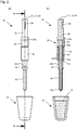
- FIGS. 1a to 2b a first embodiment of a magnetic separation device according to the invention is generally designated 10. Below the magnetic separation device is an exemplified sample vessel 12, in which, as in FIG. 1b is shown, a suspension 14 is located with magnetic particles.
- the magnetic separator 10 extends along a device axis V, which is also included in the cutting plane Ib-Ib.
- the device axis V is parallel to the plane of the drawing FIG. 1 , the cutting plane Ib-Ib orthogonal to this.
- the magnetic separator 10 has a soft-magnetic tip 16, which, as in the example shown, may be formed as a cylindrical component, the cylinder axis or generally the longitudinal axis L of the soft-elastic tip 16 coinciding with the device axis V.
- the soft-magnetic tip 16 has an immersion end 16a closer to the container 12 and has a magnetization section 16b, which in the present example, as will be explained in more detail below, is structurally formed by the longitudinal end opposite the insertion end 16a.
- the soft magnetic tip 16 may be surrounded at its plunging end 16a by an interleaving sleeve 18 by which the material of the tip 16 may be shielded from the suspension 14 into which the plunging end 16a of the tip 16 operates by moving along the device axis V. - and immersed as intended.
- the change sheath 18 is a detachable and replaceable provided at the top 16 protective cover.
- the soft magnetic tip 16 is clamped with its magnetization section 16b in a socket portion 20a of a support member 20, for example, shrunk or screwed, glued, soldered and the like.
- a first magnet assembly 22 as a magnetizing magnet assembly 22 along the device axis V is movably received.
- the carrier component 20 has a cavity 24, which is designed to be longer axially than the magnetization magnet arrangement 22 and in which the magnetization magnet arrangement 22 is axially movable relative to the device axis V.
- the support member 20 is preferably formed of non-magnetizable material, it may be formed of plastic, aluminum, brass and the like.
- a stub shaft 26 connects to the carrier component 20, which in the illustrated example axially closes off the recess 24 in the carrier component 20.
- the stub shaft 26 has a recess 28 for receiving a in the FIGS. 1 and 2 Key, not shown, by means of which torque from a hub, also not shown on the stub shaft 26 is transferable to drive the stub shaft 26 and with this the device 10 in total for rotation about the device axis V as a rotation axis.
- the non-rotatably coupled to the stub shaft 26 soft magnetic tip 16 can be set in rotation about its longitudinal axis L, whereby in the radial direction relative to the device axis V acting centrifugal forces on possibly at the immersion End 16a of the soft magnetic tip 16 adhering magnetic particles can be exerted to either separate to this still adhering suspension liquid of these, or to facilitate the separation of the magnetic particles from the immersion end 16a of the soft magnetic tip 16.
- the rotary drive for the magnetic separator 10 is in the FIGS. 1 to 4 not shown.
- the stub shaft 26 has soft magnetic material at least at its longitudinal end 26a, which is closer to the carrier component 22, so that the magnetization magnet device 22 in the in FIG. 1b shown non-magnetization position on the soft magnetic material of the longitudinal end 26a of the stub shaft 26 physically abuts and so creates a magnetic circuit with this.
- a drive magnet assembly 30 is provided which surrounds a portion of the support member 20 radially outward.
- the drive magnet assembly 30 also surrounds the magnetization magnet assembly 22 radially outward.
- the magnetization magnet arrangement is preferably formed from one or more permanent magnets
- the magnetization magnet arrangement is preferably magnetized along the device axis V so that, for example, its end 22a facing the tip 16 has a magnetic south pole and its opposite longitudinal end 22b facing the stub shaft 26 has a magnetic north pole
- the drive magnet assembly 30 is preferably formed by an electromagnet, that is, by a bestrombare coil.
- the coil axis S preferably coincides with the device axis V as well as an axis of symmetry M of the magnetization magnet arrangement 22.
- a magnetic field can temporarily be generated in the drive magnet assembly 30, which applies a magnitude larger and oppositely directed force to the magnetization magnet assembly 22 with a suitable polarity than the magnetic closure between the longitudinal end 22b and acting as a holding device longitudinal end 26a of Shaft stub 26.
- a magnetic field By a momentary Bestromungsimpuls a magnetic field can temporarily be generated in the drive magnet assembly 30, which applies a magnitude larger and oppositely directed force to the magnetization magnet assembly 22 with a suitable polarity than the magnetic closure between the longitudinal end 22b and acting as a holding device longitudinal end 26a of Shaft stub 26.
- the longitudinal end 22a of the magnetization magnet assembly 22 physically contacts the magnetization portion 16b of the soft magnetic tip 16 and forms a magnetic circuit therewith, whereby the soft magnetic tip 16 itself is magnetized for the duration of this magnet closure.
- the soft magnetic tip 16 when the soft magnetic tip 16 is magnetized, the magnetic particles in the suspension 14 deposit at the dip end 16a of the tip 16 when immersed in the suspension 14. As a result, the magnetic particles and with them adhering to their outside substances from the suspension 14 can be removed.
- Magnetic action between the magnetizing magnet assembly 22 and the soft magnetic tip 16 causes magnetic forces between the tip 16 and the magnetizing magnet assembly 22 to maintain the magnetizing magnet assembly 22 in the magnetizing position.
- the drive magnet assembly 30 need not be energized. This must be energized only for the duration of the release of the magnetization magnet assembly 22 of the longitudinal end 26a of the stub shaft 26 until the sum of gravity and attraction between the longitudinal end 22a and the tip 16 is greater than the attraction force between the opposite longitudinal end 22b and the Longitudinal end 26a of the stub shaft. From this condition, the further displacement of the magnetization magnet arrangement 22 into the magnetization position is carried out automatically.
- the magnetizing magnet assembly 22 since the magnetizing magnet assembly 22 must be displaced from the magnetizing position to the non-magnetizing position against the action of gravity, it may be necessary to energize the driving magnet assembly for shifting the magnetizing magnet assembly 22 to the non-magnetizing position for a longer time as for shifting to the opposite Direction. However, this also does not contribute significantly to the heat development, since the energization in any case need not be continued beyond the duration of the shift out. After reaching the longitudinal end 26a of the stub shaft 26 and after making a magnetic circuit with this, the magnetizing magnet device 22 remains again in the non-magnetization position.
- the soft magnetic material of the tip 16 is substantially not magnetized, so that upon immersion of the immersion end 16a in the suspension 14 no magnetic particles attach to it.
- FIGS. 3a to 4b a second embodiment of the present invention is shown. This second embodiment will be described below only insofar as they differ from the first embodiment described above FIGS. 1a to 2b otherwise, the description of which expressly refers to the description of the second embodiment.
- the magnetization magnet assembly 122 is arranged to be non-displaceable relative to the soft magnetic tip 116. With its longitudinal end 122b facing away from the tip 116, the magnetization magnet assembly 122 is in permanent abutment with the longitudinal end 126a of the stub shaft 126. In the present case, magnetic holding forces between the stub shaft 126 and the magnetization magnet assembly 122 are not important the stub shaft 126 in the second embodiment may be made of any material. The longitudinal end 126a does not need to be soft magnetic.
- the magnetization magnet assembly 122 With its tip end 116 facing longitudinal end 122a, the magnetization magnet assembly 122 is permanently in magnetic contact with the magnetization section 116b of the tip 116, this magnetic closure is indirectly produced in the present example via interposition of a soft magnetic intermediate member 134 which at one end with the magnetization magnet assembly 122nd and the other end is in physical contact with the soft magnetic tip 116, in particular with its magnetization portion 116b.
- the soft magnetic tip 116 may be additionally coupled to the intermediate member 134 by a ring coupling 136.
- the ring coupling 136 may be formed of soft magnetic material.
- the soft magnetic tip 116 of the second embodiment may be replaceably provided on the device 110.
- the intermediate component 134 is preferably designed and arranged rotationally symmetrical with respect to the device axis V.
- the soft magnetic tip 116 is magnetized so that in this state it is prepared to remove magnetic particles from the suspension 114.
- the magnetization state of the tip 116 is controlled in the second embodiment by a switching magnet assembly 130 which is displaceable relative to the magnetization magnet assembly 122.
- the switching magnet arrangement 130 is displaceable along the device axis V. It is located in FIG. 3 in its tip 116 further on position in which the magnetization magnet assembly 122 is "turned on” so that it causes a magnetization of the tip 116.
- the switch magnet assembly 130 is coaxial with the magnetization magnet assembly 122 so that its magnet assembly longitudinal axis is aligned with the device axis V coincides. The same applies to the axis M of the magnetization magnet arrangement 122.
- the switch magnet assembly 130 has one or more permanent magnets polarized along the device axis V, the polarization being opposite that of the magnetization magnet assembly 122.
- the switching magnet assembly 130 forms, at its longitudinal end closer to the tip 116, a magnetic pole which is unlike that of the longitudinal end 122a of the magnetizing magnet assembly 122.
- the opposite magnetic pole at the longitudinal end 130b with respect to the magnetic pole at the longitudinal end 122b of the magnetizing magnet assembly 122, the same applies. This is the in FIG. 3 shown switching position of the switching magnet assembly 130 relative to the magnetizing magnet assembly 122 a stable state.
- another magnet assembly 132 is provided, which surrounds the switching magnet assembly 130 radially outward in the example shown.
- the further magnet arrangement 132 which acts as a triggering magnet arrangement 132 in the sense of the introduction of the description, can also be arranged axially next to the switching magnet arrangement 130 or can be formed in a plurality of preferably coaxial sections and surround the switching magnet arrangement 130 between its sections.
- the arrangement shown in the present example allows realization of an axially particularly short component of switching and tripping magnet arrangement.
- the trigger magnet assembly 132 which forms a potential source of heat as an electromagnet, must be energized only for a short time, the energization time due to the gravity support in the shift from the on position to the off position may be shorter than vice versa and the energization time due to the stability of both positions : On position and off position, the duration of the displacement movement of the switching magnet assembly 130 must not exceed time. Due to the short-term nature of the energization of the triggering magnet arrangement 132, its effect as a heat source is negligible.
- Both embodiments shown allow a radially extremely slim design, which allows the integration of the magnetic separation device shown in a pipetting, in particular in a pipetting head, wherein the magnetic separation device can then replace a pipetting in the pipetting.
- the radial dimension of the predominantly-with the exception of a few component sections-rotationally symmetrical with respect to the device axis V formed magnetic separation device is preferably less than 20 mm in diameter, more preferably less than 18 mm in diameter.
Landscapes
- Apparatus Associated With Microorganisms And Enzymes (AREA)
- Electromagnets (AREA)
- Physical Or Chemical Processes And Apparatus (AREA)
Applications Claiming Priority (3)
| Application Number | Priority Date | Filing Date | Title |
|---|---|---|---|
| DE102015218010.7A DE102015218010A1 (de) | 2015-09-18 | 2015-09-18 | Magnetische Trennvorrichtung mit magnetischer Aktivierung und Deaktivierung |
| EP16766940.7A EP3349909B1 (fr) | 2015-09-18 | 2016-09-15 | Dispositif de séparation magnétique à activation et désactivation magnétique |
| PCT/EP2016/071804 WO2017046234A1 (fr) | 2015-09-18 | 2016-09-15 | Dispositif de séparation magnétique à activation et désactivation magnétique |
Related Parent Applications (2)
| Application Number | Title | Priority Date | Filing Date |
|---|---|---|---|
| EP16766940.7A Division EP3349909B1 (fr) | 2015-09-18 | 2016-09-15 | Dispositif de séparation magnétique à activation et désactivation magnétique |
| EP16766940.7A Division-Into EP3349909B1 (fr) | 2015-09-18 | 2016-09-15 | Dispositif de séparation magnétique à activation et désactivation magnétique |
Publications (2)
| Publication Number | Publication Date |
|---|---|
| EP3461560A1 true EP3461560A1 (fr) | 2019-04-03 |
| EP3461560B1 EP3461560B1 (fr) | 2020-04-29 |
Family
ID=56943527
Family Applications (2)
| Application Number | Title | Priority Date | Filing Date |
|---|---|---|---|
| EP16766940.7A Active EP3349909B1 (fr) | 2015-09-18 | 2016-09-15 | Dispositif de séparation magnétique à activation et désactivation magnétique |
| EP18204538.5A Active EP3461560B1 (fr) | 2015-09-18 | 2016-09-15 | Dispositif de séparation magnétique à activation et désactivation magnétiques |
Family Applications Before (1)
| Application Number | Title | Priority Date | Filing Date |
|---|---|---|---|
| EP16766940.7A Active EP3349909B1 (fr) | 2015-09-18 | 2016-09-15 | Dispositif de séparation magnétique à activation et désactivation magnétique |
Country Status (3)
| Country | Link |
|---|---|
| EP (2) | EP3349909B1 (fr) |
| DE (1) | DE102015218010A1 (fr) |
| WO (1) | WO2017046234A1 (fr) |
Families Citing this family (3)
| Publication number | Priority date | Publication date | Assignee | Title |
|---|---|---|---|---|
| EP3147028B1 (fr) * | 2015-09-25 | 2019-06-19 | Constantin Odefey | Procede et dispositif de separation magnetique de nanobilles |
| WO2018049483A1 (fr) | 2016-09-16 | 2018-03-22 | The University Of Western Australia | Outil magnétique et procédé de collecte de particules magnétiques utilisant celui-ci |
| DE102016219053A1 (de) | 2016-09-30 | 2018-04-05 | Hamilton Bonaduz Ag | Magnetische Trennvorrichtung mit unkörperlicher Kopplung zwischen Magnetanordnung und deren Bewegungsantrieb |
Citations (8)
| Publication number | Priority date | Publication date | Assignee | Title |
|---|---|---|---|---|
| US2693979A (en) * | 1950-08-03 | 1954-11-09 | George L Russell | Magnetic device |
| US5647994A (en) * | 1993-06-21 | 1997-07-15 | Labsystems Oy | Method and apparatus for separating magnetic particles from a solution |
| WO2002040173A1 (fr) * | 2000-11-18 | 2002-05-23 | Forschungszentrum Karlsruhe Gmbh | Procede de separation d'un produit disperse ou dissous et separateur magnetique y relatif |
| US6409925B1 (en) * | 1998-02-06 | 2002-06-25 | Bio-Magnetics Ltd. | Device and system for transfer of material |
| WO2004035217A1 (fr) * | 2002-10-18 | 2004-04-29 | Bio-Nobile Oy | Procede de transfert magnetique, dispositif permettant de transferer des microparticules et unite de reacteur |
| US20060269385A1 (en) * | 2005-05-24 | 2006-11-30 | Festo Corporation | Apparatus and method for transferring samples from a source to a target |
| US20080170966A1 (en) * | 2007-01-16 | 2008-07-17 | Festo Corporation | Flux Concentrator for Biomagnetic Particle Transfer Device |
| US20090189464A1 (en) * | 2008-01-25 | 2009-07-30 | Luminex Corporation | Solenoid Actuator |
Family Cites Families (5)
| Publication number | Priority date | Publication date | Assignee | Title |
|---|---|---|---|---|
| FR2554016B1 (fr) | 1983-10-27 | 1986-08-08 | Pasteur Institut | Perfectionnements apportes aux moyens magnetiques destines a retirer des billes de gel magnetique d'un fluide de dosage |
| FR2572178B1 (fr) | 1984-10-23 | 1988-10-28 | Pasteur Institut | Nouveau dispositif magnetique destine a retirer des billes de gel magnetique d'un milieu a analyser et a les transferer sur un milieu de dosage immunoenzymatique |
| US5567326A (en) | 1994-09-19 | 1996-10-22 | Promega Corporation | Multisample magnetic separation device |
| DE10331254B4 (de) | 2003-07-10 | 2006-05-04 | Chemagen Biopolymer-Technologie Aktiengesellschaft | Vorrichtung und Verfahren zum Abtrennen von magnetischen oder magnetisierbaren Partikeln aus einer Flüssigkeit |
| DE102005004664B4 (de) | 2005-02-02 | 2007-06-21 | Chemagen Biopolymer-Technologie Aktiengesellschaft | Vorrichtung und Verfahren und Verwendung zum Abtrennen von magnetischen oder magnetisierbaren Partikeln aus einer Flüssigkeit sowie deren Verwendungen |
-
2015
- 2015-09-18 DE DE102015218010.7A patent/DE102015218010A1/de not_active Withdrawn
-
2016
- 2016-09-15 EP EP16766940.7A patent/EP3349909B1/fr active Active
- 2016-09-15 WO PCT/EP2016/071804 patent/WO2017046234A1/fr not_active Ceased
- 2016-09-15 EP EP18204538.5A patent/EP3461560B1/fr active Active
Patent Citations (8)
| Publication number | Priority date | Publication date | Assignee | Title |
|---|---|---|---|---|
| US2693979A (en) * | 1950-08-03 | 1954-11-09 | George L Russell | Magnetic device |
| US5647994A (en) * | 1993-06-21 | 1997-07-15 | Labsystems Oy | Method and apparatus for separating magnetic particles from a solution |
| US6409925B1 (en) * | 1998-02-06 | 2002-06-25 | Bio-Magnetics Ltd. | Device and system for transfer of material |
| WO2002040173A1 (fr) * | 2000-11-18 | 2002-05-23 | Forschungszentrum Karlsruhe Gmbh | Procede de separation d'un produit disperse ou dissous et separateur magnetique y relatif |
| WO2004035217A1 (fr) * | 2002-10-18 | 2004-04-29 | Bio-Nobile Oy | Procede de transfert magnetique, dispositif permettant de transferer des microparticules et unite de reacteur |
| US20060269385A1 (en) * | 2005-05-24 | 2006-11-30 | Festo Corporation | Apparatus and method for transferring samples from a source to a target |
| US20080170966A1 (en) * | 2007-01-16 | 2008-07-17 | Festo Corporation | Flux Concentrator for Biomagnetic Particle Transfer Device |
| US20090189464A1 (en) * | 2008-01-25 | 2009-07-30 | Luminex Corporation | Solenoid Actuator |
Also Published As
| Publication number | Publication date |
|---|---|
| EP3461560B1 (fr) | 2020-04-29 |
| WO2017046234A1 (fr) | 2017-03-23 |
| DE102015218010A1 (de) | 2017-03-23 |
| EP3349909B1 (fr) | 2020-05-06 |
| EP3349909A1 (fr) | 2018-07-25 |
Similar Documents
| Publication | Publication Date | Title |
|---|---|---|
| EP0406782B1 (fr) | Dispositif de retenue électro-magnétique | |
| EP2973618B1 (fr) | Dispositif de réglage électromagnétique | |
| WO2008155119A1 (fr) | Dispositif de réglage électromagnétique | |
| DE102011014192B4 (de) | Elektromagnetische Aktuatorvorrichtung | |
| EP3461560B1 (fr) | Dispositif de séparation magnétique à activation et désactivation magnétiques | |
| DE19608953A1 (de) | Bistabiler Kleinmagnet | |
| DE102004059342B4 (de) | Greif- oder Spannvorrichtung | |
| DE602004007646T3 (de) | Elektromagnetischer antrieb | |
| EP2474009A1 (fr) | Dispositif d'actionnement électromagnétique bistable | |
| EP4128291B1 (fr) | Actionneur electromagnetique et son utilisation | |
| DE102013102276B4 (de) | Verdrehschutz | |
| DE102017211257B4 (de) | Elektromagnetischer Antrieb und damit ausgestattetes Ventil | |
| DE10313144B3 (de) | Magnetischer Linearantrieb | |
| EP3349910B1 (fr) | Dispositif de séparation magnétique à activation et désactivation mécanique | |
| EP3500149B1 (fr) | Actionneur électromagnétique pour instrument chirurgical | |
| DE112023000340T5 (de) | Elektromagnetischer aktuator, elektromagnetisches ventil und taktiles anzeigemodul | |
| DE102016111908B4 (de) | Greifvorrichtung zum Greifen von ferromagnetischen Gegenständen | |
| DE102005005805B3 (de) | Greifvorrichtung | |
| DE19832694C2 (de) | Polreibungsbremse | |
| DE102015103169A1 (de) | Stellvorrichtung mit eingehängten Stößeln | |
| EP2624421B1 (fr) | Axe linéaire avec entraînement électrique et fixation de fin sans courant | |
| EP0463590A2 (fr) | Dispositif d'entraînement pour réglage de deux positions à auto-maintien | |
| DE8314915U1 (de) | Pneumatisch betätigter Kontaktstift |
Legal Events
| Date | Code | Title | Description |
|---|---|---|---|
| PUAI | Public reference made under article 153(3) epc to a published international application that has entered the european phase |
Free format text: ORIGINAL CODE: 0009012 |
|
| STAA | Information on the status of an ep patent application or granted ep patent |
Free format text: STATUS: REQUEST FOR EXAMINATION WAS MADE |
|
| 17P | Request for examination filed |
Effective date: 20181106 |
|
| AC | Divisional application: reference to earlier application |
Ref document number: 3349909 Country of ref document: EP Kind code of ref document: P |
|
| AK | Designated contracting states |
Kind code of ref document: A1 Designated state(s): AL AT BE BG CH CY CZ DE DK EE ES FI FR GB GR HR HU IE IS IT LI LT LU LV MC MK MT NL NO PL PT RO RS SE SI SK SM TR |
|
| GRAP | Despatch of communication of intention to grant a patent |
Free format text: ORIGINAL CODE: EPIDOSNIGR1 |
|
| STAA | Information on the status of an ep patent application or granted ep patent |
Free format text: STATUS: GRANT OF PATENT IS INTENDED |
|
| RIC1 | Information provided on ipc code assigned before grant |
Ipc: B03C 1/033 20060101AFI20191029BHEP Ipc: B03C 1/28 20060101ALI20191029BHEP Ipc: B03C 1/034 20060101ALI20191029BHEP |
|
| INTG | Intention to grant announced |
Effective date: 20191114 |
|
| GRAS | Grant fee paid |
Free format text: ORIGINAL CODE: EPIDOSNIGR3 |
|
| GRAA | (expected) grant |
Free format text: ORIGINAL CODE: 0009210 |
|
| STAA | Information on the status of an ep patent application or granted ep patent |
Free format text: STATUS: THE PATENT HAS BEEN GRANTED |
|
| AC | Divisional application: reference to earlier application |
Ref document number: 3349909 Country of ref document: EP Kind code of ref document: P |
|
| AK | Designated contracting states |
Kind code of ref document: B1 Designated state(s): AL AT BE BG CH CY CZ DE DK EE ES FI FR GB GR HR HU IE IS IT LI LT LU LV MC MK MT NL NO PL PT RO RS SE SI SK SM TR |
|
| REG | Reference to a national code |
Ref country code: GB Ref legal event code: FG4D Free format text: NOT ENGLISH |
|
| REG | Reference to a national code |
Ref country code: CH Ref legal event code: EP |
|
| REG | Reference to a national code |
Ref country code: DE Ref legal event code: R096 Ref document number: 502016009796 Country of ref document: DE |
|
| REG | Reference to a national code |
Ref country code: CH Ref legal event code: NV Representative=s name: E. BLUM AND CO. AG PATENT- UND MARKENANWAELTE , CH Ref country code: AT Ref legal event code: REF Ref document number: 1262502 Country of ref document: AT Kind code of ref document: T Effective date: 20200515 |
|
| REG | Reference to a national code |
Ref country code: IE Ref legal event code: FG4D Free format text: LANGUAGE OF EP DOCUMENT: GERMAN |
|
| REG | Reference to a national code |
Ref country code: NL Ref legal event code: MP Effective date: 20200429 |
|
| REG | Reference to a national code |
Ref country code: LT Ref legal event code: MG4D |
|
| PG25 | Lapsed in a contracting state [announced via postgrant information from national office to epo] |
Ref country code: GR Free format text: LAPSE BECAUSE OF FAILURE TO SUBMIT A TRANSLATION OF THE DESCRIPTION OR TO PAY THE FEE WITHIN THE PRESCRIBED TIME-LIMIT Effective date: 20200730 Ref country code: PT Free format text: LAPSE BECAUSE OF FAILURE TO SUBMIT A TRANSLATION OF THE DESCRIPTION OR TO PAY THE FEE WITHIN THE PRESCRIBED TIME-LIMIT Effective date: 20200831 Ref country code: IS Free format text: LAPSE BECAUSE OF FAILURE TO SUBMIT A TRANSLATION OF THE DESCRIPTION OR TO PAY THE FEE WITHIN THE PRESCRIBED TIME-LIMIT Effective date: 20200829 Ref country code: NO Free format text: LAPSE BECAUSE OF FAILURE TO SUBMIT A TRANSLATION OF THE DESCRIPTION OR TO PAY THE FEE WITHIN THE PRESCRIBED TIME-LIMIT Effective date: 20200729 Ref country code: SE Free format text: LAPSE BECAUSE OF FAILURE TO SUBMIT A TRANSLATION OF THE DESCRIPTION OR TO PAY THE FEE WITHIN THE PRESCRIBED TIME-LIMIT Effective date: 20200429 Ref country code: FI Free format text: LAPSE BECAUSE OF FAILURE TO SUBMIT A TRANSLATION OF THE DESCRIPTION OR TO PAY THE FEE WITHIN THE PRESCRIBED TIME-LIMIT Effective date: 20200429 Ref country code: LT Free format text: LAPSE BECAUSE OF FAILURE TO SUBMIT A TRANSLATION OF THE DESCRIPTION OR TO PAY THE FEE WITHIN THE PRESCRIBED TIME-LIMIT Effective date: 20200429 |
|
| PG25 | Lapsed in a contracting state [announced via postgrant information from national office to epo] |
Ref country code: RS Free format text: LAPSE BECAUSE OF FAILURE TO SUBMIT A TRANSLATION OF THE DESCRIPTION OR TO PAY THE FEE WITHIN THE PRESCRIBED TIME-LIMIT Effective date: 20200429 Ref country code: LV Free format text: LAPSE BECAUSE OF FAILURE TO SUBMIT A TRANSLATION OF THE DESCRIPTION OR TO PAY THE FEE WITHIN THE PRESCRIBED TIME-LIMIT Effective date: 20200429 Ref country code: BG Free format text: LAPSE BECAUSE OF FAILURE TO SUBMIT A TRANSLATION OF THE DESCRIPTION OR TO PAY THE FEE WITHIN THE PRESCRIBED TIME-LIMIT Effective date: 20200729 Ref country code: HR Free format text: LAPSE BECAUSE OF FAILURE TO SUBMIT A TRANSLATION OF THE DESCRIPTION OR TO PAY THE FEE WITHIN THE PRESCRIBED TIME-LIMIT Effective date: 20200429 |
|
| PG25 | Lapsed in a contracting state [announced via postgrant information from national office to epo] |
Ref country code: NL Free format text: LAPSE BECAUSE OF FAILURE TO SUBMIT A TRANSLATION OF THE DESCRIPTION OR TO PAY THE FEE WITHIN THE PRESCRIBED TIME-LIMIT Effective date: 20200429 Ref country code: AL Free format text: LAPSE BECAUSE OF FAILURE TO SUBMIT A TRANSLATION OF THE DESCRIPTION OR TO PAY THE FEE WITHIN THE PRESCRIBED TIME-LIMIT Effective date: 20200429 |
|
| PG25 | Lapsed in a contracting state [announced via postgrant information from national office to epo] |
Ref country code: IT Free format text: LAPSE BECAUSE OF FAILURE TO SUBMIT A TRANSLATION OF THE DESCRIPTION OR TO PAY THE FEE WITHIN THE PRESCRIBED TIME-LIMIT Effective date: 20200429 Ref country code: EE Free format text: LAPSE BECAUSE OF FAILURE TO SUBMIT A TRANSLATION OF THE DESCRIPTION OR TO PAY THE FEE WITHIN THE PRESCRIBED TIME-LIMIT Effective date: 20200429 Ref country code: SM Free format text: LAPSE BECAUSE OF FAILURE TO SUBMIT A TRANSLATION OF THE DESCRIPTION OR TO PAY THE FEE WITHIN THE PRESCRIBED TIME-LIMIT Effective date: 20200429 Ref country code: DK Free format text: LAPSE BECAUSE OF FAILURE TO SUBMIT A TRANSLATION OF THE DESCRIPTION OR TO PAY THE FEE WITHIN THE PRESCRIBED TIME-LIMIT Effective date: 20200429 Ref country code: ES Free format text: LAPSE BECAUSE OF FAILURE TO SUBMIT A TRANSLATION OF THE DESCRIPTION OR TO PAY THE FEE WITHIN THE PRESCRIBED TIME-LIMIT Effective date: 20200429 Ref country code: RO Free format text: LAPSE BECAUSE OF FAILURE TO SUBMIT A TRANSLATION OF THE DESCRIPTION OR TO PAY THE FEE WITHIN THE PRESCRIBED TIME-LIMIT Effective date: 20200429 Ref country code: CZ Free format text: LAPSE BECAUSE OF FAILURE TO SUBMIT A TRANSLATION OF THE DESCRIPTION OR TO PAY THE FEE WITHIN THE PRESCRIBED TIME-LIMIT Effective date: 20200429 |
|
| REG | Reference to a national code |
Ref country code: DE Ref legal event code: R097 Ref document number: 502016009796 Country of ref document: DE |
|
| PG25 | Lapsed in a contracting state [announced via postgrant information from national office to epo] |
Ref country code: SK Free format text: LAPSE BECAUSE OF FAILURE TO SUBMIT A TRANSLATION OF THE DESCRIPTION OR TO PAY THE FEE WITHIN THE PRESCRIBED TIME-LIMIT Effective date: 20200429 Ref country code: PL Free format text: LAPSE BECAUSE OF FAILURE TO SUBMIT A TRANSLATION OF THE DESCRIPTION OR TO PAY THE FEE WITHIN THE PRESCRIBED TIME-LIMIT Effective date: 20200429 |
|
| PLBE | No opposition filed within time limit |
Free format text: ORIGINAL CODE: 0009261 |
|
| STAA | Information on the status of an ep patent application or granted ep patent |
Free format text: STATUS: NO OPPOSITION FILED WITHIN TIME LIMIT |
|
| 26N | No opposition filed |
Effective date: 20210201 |
|
| GBPC | Gb: european patent ceased through non-payment of renewal fee |
Effective date: 20200915 |
|
| PG25 | Lapsed in a contracting state [announced via postgrant information from national office to epo] |
Ref country code: SI Free format text: LAPSE BECAUSE OF FAILURE TO SUBMIT A TRANSLATION OF THE DESCRIPTION OR TO PAY THE FEE WITHIN THE PRESCRIBED TIME-LIMIT Effective date: 20200429 |
|
| REG | Reference to a national code |
Ref country code: BE Ref legal event code: MM Effective date: 20200930 |
|
| PG25 | Lapsed in a contracting state [announced via postgrant information from national office to epo] |
Ref country code: LU Free format text: LAPSE BECAUSE OF NON-PAYMENT OF DUE FEES Effective date: 20200915 |
|
| PG25 | Lapsed in a contracting state [announced via postgrant information from national office to epo] |
Ref country code: FR Free format text: LAPSE BECAUSE OF NON-PAYMENT OF DUE FEES Effective date: 20200930 |
|
| PG25 | Lapsed in a contracting state [announced via postgrant information from national office to epo] |
Ref country code: BE Free format text: LAPSE BECAUSE OF NON-PAYMENT OF DUE FEES Effective date: 20200930 Ref country code: GB Free format text: LAPSE BECAUSE OF NON-PAYMENT OF DUE FEES Effective date: 20200915 Ref country code: IE Free format text: LAPSE BECAUSE OF NON-PAYMENT OF DUE FEES Effective date: 20200915 |
|
| PG25 | Lapsed in a contracting state [announced via postgrant information from national office to epo] |
Ref country code: TR Free format text: LAPSE BECAUSE OF FAILURE TO SUBMIT A TRANSLATION OF THE DESCRIPTION OR TO PAY THE FEE WITHIN THE PRESCRIBED TIME-LIMIT Effective date: 20200429 Ref country code: MT Free format text: LAPSE BECAUSE OF FAILURE TO SUBMIT A TRANSLATION OF THE DESCRIPTION OR TO PAY THE FEE WITHIN THE PRESCRIBED TIME-LIMIT Effective date: 20200429 Ref country code: CY Free format text: LAPSE BECAUSE OF FAILURE TO SUBMIT A TRANSLATION OF THE DESCRIPTION OR TO PAY THE FEE WITHIN THE PRESCRIBED TIME-LIMIT Effective date: 20200429 |
|
| PG25 | Lapsed in a contracting state [announced via postgrant information from national office to epo] |
Ref country code: MK Free format text: LAPSE BECAUSE OF FAILURE TO SUBMIT A TRANSLATION OF THE DESCRIPTION OR TO PAY THE FEE WITHIN THE PRESCRIBED TIME-LIMIT Effective date: 20200429 Ref country code: MC Free format text: LAPSE BECAUSE OF FAILURE TO SUBMIT A TRANSLATION OF THE DESCRIPTION OR TO PAY THE FEE WITHIN THE PRESCRIBED TIME-LIMIT Effective date: 20200429 |
|
| PGFP | Annual fee paid to national office [announced via postgrant information from national office to epo] |
Ref country code: DE Payment date: 20220818 Year of fee payment: 7 |
|
| REG | Reference to a national code |
Ref country code: AT Ref legal event code: MM01 Ref document number: 1262502 Country of ref document: AT Kind code of ref document: T Effective date: 20210915 |
|
| PG25 | Lapsed in a contracting state [announced via postgrant information from national office to epo] |
Ref country code: AT Free format text: LAPSE BECAUSE OF NON-PAYMENT OF DUE FEES Effective date: 20210915 |
|
| PGFP | Annual fee paid to national office [announced via postgrant information from national office to epo] |
Ref country code: CH Payment date: 20221001 Year of fee payment: 7 |
|
| P01 | Opt-out of the competence of the unified patent court (upc) registered |
Effective date: 20230521 |
|
| REG | Reference to a national code |
Ref country code: DE Ref legal event code: R119 Ref document number: 502016009796 Country of ref document: DE |
|
| REG | Reference to a national code |
Ref country code: CH Ref legal event code: PL |
|
| PG25 | Lapsed in a contracting state [announced via postgrant information from national office to epo] |
Ref country code: CH Free format text: LAPSE BECAUSE OF NON-PAYMENT OF DUE FEES Effective date: 20230930 |
|
| PG25 | Lapsed in a contracting state [announced via postgrant information from national office to epo] |
Ref country code: DE Free format text: LAPSE BECAUSE OF NON-PAYMENT OF DUE FEES Effective date: 20240403 Ref country code: CH Free format text: LAPSE BECAUSE OF NON-PAYMENT OF DUE FEES Effective date: 20230930 |