EP3350567B1 - Procédé et dispositif de mesure pour la détermination de la compressibilité d'un fluide en écoulement - Google Patents
Procédé et dispositif de mesure pour la détermination de la compressibilité d'un fluide en écoulement Download PDFInfo
- Publication number
- EP3350567B1 EP3350567B1 EP16754530.0A EP16754530A EP3350567B1 EP 3350567 B1 EP3350567 B1 EP 3350567B1 EP 16754530 A EP16754530 A EP 16754530A EP 3350567 B1 EP3350567 B1 EP 3350567B1
- Authority
- EP
- European Patent Office
- Prior art keywords
- pressure
- density
- fluid
- value
- measurement value
- Prior art date
- Legal status (The legal status is an assumption and is not a legal conclusion. Google has not performed a legal analysis and makes no representation as to the accuracy of the status listed.)
- Active
Links
Images

Classifications
-
- G—PHYSICS
- G01—MEASURING; TESTING
- G01N—INVESTIGATING OR ANALYSING MATERIALS BY DETERMINING THEIR CHEMICAL OR PHYSICAL PROPERTIES
- G01N9/00—Investigating density or specific gravity of materials; Analysing materials by determining density or specific gravity
- G01N9/26—Investigating density or specific gravity of materials; Analysing materials by determining density or specific gravity by measuring pressure differences
-
- G—PHYSICS
- G01—MEASURING; TESTING
- G01F—MEASURING VOLUME, VOLUME FLOW, MASS FLOW OR LIQUID LEVEL; METERING BY VOLUME
- G01F1/00—Measuring the volume flow or mass flow of fluid or fluent solid material wherein the fluid passes through a meter in a continuous flow
- G01F1/05—Measuring the volume flow or mass flow of fluid or fluent solid material wherein the fluid passes through a meter in a continuous flow by using mechanical effects
- G01F1/34—Measuring the volume flow or mass flow of fluid or fluent solid material wherein the fluid passes through a meter in a continuous flow by using mechanical effects by measuring pressure or differential pressure
- G01F1/36—Measuring the volume flow or mass flow of fluid or fluent solid material wherein the fluid passes through a meter in a continuous flow by using mechanical effects by measuring pressure or differential pressure the pressure or differential pressure being created by the use of flow constriction
-
- G—PHYSICS
- G01—MEASURING; TESTING
- G01F—MEASURING VOLUME, VOLUME FLOW, MASS FLOW OR LIQUID LEVEL; METERING BY VOLUME
- G01F1/00—Measuring the volume flow or mass flow of fluid or fluent solid material wherein the fluid passes through a meter in a continuous flow
- G01F1/05—Measuring the volume flow or mass flow of fluid or fluent solid material wherein the fluid passes through a meter in a continuous flow by using mechanical effects
- G01F1/34—Measuring the volume flow or mass flow of fluid or fluent solid material wherein the fluid passes through a meter in a continuous flow by using mechanical effects by measuring pressure or differential pressure
- G01F1/36—Measuring the volume flow or mass flow of fluid or fluent solid material wherein the fluid passes through a meter in a continuous flow by using mechanical effects by measuring pressure or differential pressure the pressure or differential pressure being created by the use of flow constriction
- G01F1/40—Details of construction of the flow constriction devices
- G01F1/44—Venturi tubes
-
- G—PHYSICS
- G01—MEASURING; TESTING
- G01F—MEASURING VOLUME, VOLUME FLOW, MASS FLOW OR LIQUID LEVEL; METERING BY VOLUME
- G01F1/00—Measuring the volume flow or mass flow of fluid or fluent solid material wherein the fluid passes through a meter in a continuous flow
- G01F1/76—Devices for measuring mass flow of a fluid or a fluent solid material
- G01F1/78—Direct mass flowmeters
- G01F1/80—Direct mass flowmeters operating by measuring pressure, force, momentum, or frequency of a fluid flow to which a rotational movement has been imparted
- G01F1/84—Coriolis or gyroscopic mass flowmeters
-
- G—PHYSICS
- G01—MEASURING; TESTING
- G01F—MEASURING VOLUME, VOLUME FLOW, MASS FLOW OR LIQUID LEVEL; METERING BY VOLUME
- G01F15/00—Details of, or accessories for, apparatus of groups G01F1/00 - G01F13/00 insofar as such details or appliances are not adapted to particular types of such apparatus
- G01F15/005—Valves
-
- G—PHYSICS
- G01—MEASURING; TESTING
- G01F—MEASURING VOLUME, VOLUME FLOW, MASS FLOW OR LIQUID LEVEL; METERING BY VOLUME
- G01F5/00—Measuring a proportion of the volume flow
- G01F5/005—Measuring a proportion of the volume flow by measuring pressure or differential pressure, created by the use of flow constriction
-
- G—PHYSICS
- G01—MEASURING; TESTING
- G01N—INVESTIGATING OR ANALYSING MATERIALS BY DETERMINING THEIR CHEMICAL OR PHYSICAL PROPERTIES
- G01N9/00—Investigating density or specific gravity of materials; Analysing materials by determining density or specific gravity
- G01N9/002—Investigating density or specific gravity of materials; Analysing materials by determining density or specific gravity using variation of the resonant frequency of an element vibrating in contact with the material submitted to analysis
-
- G—PHYSICS
- G01—MEASURING; TESTING
- G01F—MEASURING VOLUME, VOLUME FLOW, MASS FLOW OR LIQUID LEVEL; METERING BY VOLUME
- G01F1/00—Measuring the volume flow or mass flow of fluid or fluent solid material wherein the fluid passes through a meter in a continuous flow
- G01F1/76—Devices for measuring mass flow of a fluid or a fluent solid material
- G01F1/86—Indirect mass flowmeters, e.g. measuring volume flow and density, temperature or pressure
- G01F1/88—Indirect mass flowmeters, e.g. measuring volume flow and density, temperature or pressure with differential-pressure measurement to determine the volume flow
-
- G—PHYSICS
- G01—MEASURING; TESTING
- G01F—MEASURING VOLUME, VOLUME FLOW, MASS FLOW OR LIQUID LEVEL; METERING BY VOLUME
- G01F15/00—Details of, or accessories for, apparatus of groups G01F1/00 - G01F13/00 insofar as such details or appliances are not adapted to particular types of such apparatus
- G01F15/001—Means for regulating or setting the meter for a predetermined quantity
Definitions
- the present invention relates to a method for determining the compressibility of a flowing fluid.
- the density of a fluid at reference conditions is of interest for the evaluation of fluids.
- One solution is to calculate the density at reference pressure from a density measurement taken at a higher pressure. In order to perform this calculation reliably, the most accurate knowledge of the compressibility is required.
- Dabs is the density of the incompressible phase
- D1 and D2 are density measurements for the mixture at corresponding pressure measurements P1 and P2.
- the slip is pumped through two densimeters connected in series, whereby the pressure drop across the first densimeter causes a lower static pressure in the second densimeter.
- a medium possibly laden with gas flows through a Coriolis mass flow meter that is arranged in series between two pressure sensors. If the Coriolis mass flow meter can no longer measure the flow accurately enough due to excessive gas loading, the flow is determined based on a differential pressure measurement between the two pressure sensors. If the Coriolis mass flow meter can measure accurately enough, the transfer functions of the differential pressure measurement and the Coriolis mass flow meter are adjusted.
- the measuring system according to US 2011/0161018 A1 comprises a vibration-type transducer with an inlet-side pressure sensor for predicting a critically low pressure at the outlet of the transducer due to the flow-dependent pressure drop along the flow-through measuring tube.
- US 2005/138993 A1 describes a density meter based on the vibration principle with pulsating pressure for measuring the density of the liquid phase of gas-laden media.
- the respective gas volume fraction is determined from the mixture density at different pressure values, and once this is known, the density of the liquid phase can be calculated.
- WO 2014/158376 A1 reveals another density meter.
- the method further comprises calculating a third density value at a third pressure based on the determined compressibility and on at least one of the first and second density measurement values, wherein the third pressure differs from the first pressure and the second pressure, wherein the third pressure in particular lies outside an interval delimited by the first pressure and the second pressure.
- the method further comprises calculating a sound velocity value based on the compressibility and at least one of the density measurements.
- the determination of the compressibility is carried out under the assumption of a constant temperature of the fluid at the first pressure measurement value and the second pressure measurement value.
- a first temperature of the fluid in the measuring tube when detecting the first density measurement value differs from a second temperature of the fluid in the measuring tube when detecting the second density measurement value by no more than 5 °C, in particular no more than 2 °C and preferably no more than 1 °C.
- determining the first density measurement value and determining the second density measurement value each comprise detecting a natural frequency value of at least one bending vibration mode of the measuring tube.
- the natural frequency of the at least one bending vibration mode depends on a bending stiffness of the measuring tube, which Cross-sensitivity to the pressure of the fluid in the measuring tube, wherein the pressure-dependent bending stiffness of the measuring tube is included in the determination of the density measurement value on the basis of the recorded natural frequencies, wherein at least one of the recorded pressure measurements is used to determine the pressure-dependent bending stiffness.
- the throttle arrangement has two check valves connected in parallel, of which a first check valve has a lower operating point than a second check valve, and a check valve shut-off valve is connected upstream of the first check valve, which is in particular automatically controllable.
- the throttle arrangement has an aperture with an adjustable aperture.
- the operating and evaluation unit is designed to determine a pressure measurement value for the fluid, which is associated with a density measurement value, as an average value of pressure measurement values recorded essentially simultaneously by the first pressure sensor and the second pressure sensor.
- the operating and evaluation unit is designed to determine a density value under reference conditions, for example 1013 mbar, based on the density measurement value, the associated pressure measurement value and the determined value for the compressibility.
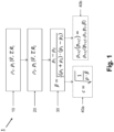
- the embodiment of a method 1 according to the invention shown comprises, in a first step 10, the detection of a first density measurement value ⁇ 1 and an associated first pressure measurement value p 1 of a flowing fluid, wherein the first Pressure of the flowing fluid is generated by pumping the fluid against a first flow resistance R 1 of a throttle arrangement with a variable flow resistance.
- a second density measurement value ⁇ 2 and an associated second pressure measurement value p 2 of a flowing fluid are recorded, wherein the first flow resistance differs from the second flow resistance.
- the first pressure can be approximately 0.5 to 1 bar while the second pressure is 5 to 10 bar.
- the density measurement can be carried out, for example, by measuring a density-dependent resonance frequency of an oscillating measuring tube through which the fluid flows.
- ⁇ ⁇ 1 ⁇ ⁇ 2 1 2 ⁇ 1 + ⁇ 2 ⁇ p 1 ⁇ p 2
- the density value can, for example, be the arithmetic mean of the two density measurements ⁇ 1 , ⁇ 2 on the basis of which the compressibility ⁇ was calculated.
- a reference density ⁇ ref can be calculated at a reference pressure p ref of, for example, 1013 mbar.
- the reference density depends on the reference pressure p ref , at least one pair of values of a pressure measurement value p i with its corresponding density measurement value ⁇ i , as well as the corresponding value for the compressibility ⁇ of the fluid.
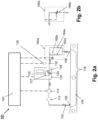
- the measuring arrangement 101 shown comprises a sampling line 102 which is guided parallel to a pipe 104 between a first connection point 106 and a second connection point 108.
- the measuring arrangement 101 further comprises in the sampling line 102 a micro gear ring pump 114, as is available from the company HNP, or another metering pump with a delivery accuracy of better than 1%, in particular better than 0.5%, for driving a defined volume flow through the fluid path 116 formed by the sampling line 102 and the components arranged therein.
- the sampling line has, for example, an inner diameter of 4 mm.
- a filter element 115 is arranged upstream of the gear ring pump 114, which filter element has, for example, a maximum pore size of not more than 20 ⁇ m, in particular not more than 10 ⁇ m and preferably not more than 5 ⁇ m, in order to ensure that subsequent components do not become clogged.
- a density meter 120 with an oscillating measuring tube 122 is arranged in the sampling line 102, which can be excited to bending vibrations by means of an exciter, the resonance frequency of which depends on the density of a medium contained in the measuring tube 122.
- the measuring tube has a diameter of 160 ⁇ m, for example, and is prepared in silicon using MEMS technology.
- the resonance frequency is, for example, in the order of 20 kHz for a low-viscosity fluid with a density of about 10 6 g/m 3 .
- the total length of a fluid path section through the measuring tube 122 and surrounding MEMS components with an inner diameter of 200 ⁇ m is approximately 1 cm.
- This fluid path section has a comparatively large flow resistance, so that it is not practical to guide the entire volume flow through the sampling line 102 via this fluid path section.
- the expected volume flows in the event of pressure drops of a few bar across the fluid path section through the measuring tube 122 would be so low that the medium in the sampling line 102 would not be reliably representative, particularly if the properties of the medium in the pipe 104 change. Therefore, the fluid path section is guided through the MEMS components as a bypass 126 parallel to an orifice 124, wherein the bypass 126 has a bypass path length of less than 20 mm, particularly less than 15 mm, for example 10 mm.
- the orifice 124 has a diameter of 0.5 to 2 mm which is dimensioned such that due to the volume flow in the extraction line 102, a pressure gradient is generated which is a portion of the volume flow of, for example, 0.1% to 5% through the bypass 126.
- the MEMS components further comprise a temperature sensor 127, for example a semiconductor resistance element, or a Pt resistance element, which in particular detects a temperature of the measuring tube 122 or near the measuring tube, which is representative of the temperature of the medium.
- the measuring arrangement 101 further comprises a pressure sensor 130 for detecting a pressure measurement value at a pressure tapping point 132, which is arranged on the fluid path 116 between the gear ring pump 140 and a throttle arrangement 160a. More precisely, the pressure tapping point is arranged here in the flow direction below the density meter.
- the pressure at the pressure tap point 132 is definitely lower than the average pressure in the measuring tube 122.
- a second pressure sensor is expressly not required to determine the compressibility, because with a constant volume flow, the pressure drop across the measuring tube is constant, so that it does not contribute to the pressure difference in equation (1).
- the throttle arrangement 160a comprises two check valves connected in parallel, of which a first check valve 162a has a lower operating point than a second check valve 164a.
- the first operating point of the first check valve 162a is, for example, 0.5 - 1 bar, while the second operating point of the second check valve 164a is 5 - 10 bar.
- An automatically controllable check valve shut-off valve 166a is connected upstream of the first check valve 162a. When the check valve shut-off valve 166a is open, the volume flow driven by the gerotor pump 114 can flow via the first check valve 162a, so that the static pressure of the flowing fluid is determined by the operating point of the first check valve 162a.
- the check valve shut-off valve 166a If, however, the check valve shut-off valve 166a is closed, the volume flow flows through the second check valve 164a, so that the static pressure is determined via the second operating point and thus has a significantly higher value.
- the static pressure can thus alternately be determined by the first operating point and the second operating point at a constant volume flow.
- the value of the static pressure of the fluid can be determined using the pressure sensor 130 with the restrictions explained above.
- the measuring arrangement 101 further comprises an operating and evaluation unit 140, which is set up to determine the compressibility of the fluid based on the value tuples for various static pressure measured values, with the respective associated density and, if applicable, temperature measured values of the flowing fluid, and thus to determine a density value under reference conditions, for example 1013 mbar.
- the operating and evaluation unit controls the check valve shut-off valve 166a to shut off the first check valve 162a.
- the electrical circuits of the differential pressure measuring arrangement, the density meter 120, and the operating and evaluation unit are preferably designed in the Exi (intrinsically safe) type of protection.
- the electronic circuit of the gear ring pump 114 is preferably also implemented in a type of protection, for example in a pressure-resistant enclosure according to class Ex-d.
- Fig. 2b A throttle arrangement 160b is shown, which is an alternative to the Fig. 2a illustrated throttle arrangement 160a in the embodiment according to Fig. 2a can be used.
- the throttle arrangement 160b has an orifice 166b with a variable flow cross-section, wherein the flow cross-section can be adjusted with an actuator that is controlled by the operating and evaluation unit 140.
- the flow cross-section By varying the flow cross-section, the pressure drop across the orifice can be varied, for example, between 0.1 and 10 bar, while the volume flow remains constant.
- the embodiment of a measuring arrangement 201 according to the invention shown comprises all components of the first embodiment. Detailed explanations of the components of the first embodiment apply accordingly to the second embodiment.
- the second embodiment also contains further components that enable the viscosity of the fluid to be determined and thus viscosity-dependent errors in the density measurement to be corrected. Together with the determination of the compressibility according to the invention, an even more precise value for the density under reference conditions can also be specified for media with a higher viscosity.
- the measuring arrangement 201 comprises a sampling line 202 which is guided parallel to a pipe 204 between a first connection point 206 and a second connection point 208.
- the measuring arrangement 201 further comprises in the sampling line 202 a micro gear ring pump 214 for driving a defined volume flow through the fluid path 216 formed by the extraction line 202 and components arranged therein.
- a filter element 215 is arranged in the extraction line 202 upstream of the gear ring pump 114 to ensure that subsequent components do not become clogged.
- a density meter 220 with an oscillating measuring tube 222 is arranged in the sampling line 202, which can be excited to bending vibrations by means of an exciter, the resonance frequency of which depends on the density of a medium contained in the measuring tube 222.
- the liquid path section through the measuring tube 222 and the subsequent MEMS components is guided as a bypass 226 parallel to an orifice 224.
- the orifice 224 has a diameter of 0.5 to 2 mm, which is dimensioned such that due to the volume flow in the sampling line 202, a pressure gradient is generated which drives a proportion of the volume flow of, for example, 0.1% to 5% through the bypass 226.
- the MEMS components further comprise a temperature sensor 227, for example a semiconductor resistance element or a Pt resistance element, which in particular detects a temperature of the measuring tube 222 or near the measuring tube, which is representative of the temperature of the medium.
- the measuring arrangement 201 further comprises a first pressure sensor 230a for detecting a pressure measurement value at a first pressure tapping point 232a, which is arranged on the fluid path 216 between the gear ring pump 240 and the density meter 220, and a second pressure sensor 230b for detecting a pressure measurement value at a second pressure tapping point 232b, which is arranged on the fluid path 116 between the density meter 220 and a throttle arrangement 160a.
- the purpose of the two pressure sensors 230a and 230b is twofold. Firstly, the weaknesses of pressure measurement with only one pressure sensor discussed in connection with the first embodiment are overcome by averaging the pressure measurement values of the first and second pressure sensors.
- the pressure drop across the density meter 220 can be calculated, from which the viscosity of the fluid can be determined for a given volume flow.
- the throttle arrangement 260 comprises two check valves connected in parallel, of which a first check valve 262 has a lower operating point than a second check valve 264.
- the first operating point of the first check valve 262 is, for example, 0.5 - 1 bar, while the second operating point of the second check valve 264 is 5 - 10 bar.
- the first check valve 262 is assigned an automatic controllable check valve shut-off valve 266 is connected upstream. When the check valve shut-off valve 266 is open, the volume flow driven by the gerotor pump 214 can flow via the first check valve 262, so that the static pressure of the flowing fluid is determined by the operating point of the first check valve 262.
- the shut-off valve 266 is closed, the volume flow flows via the second check valve 264, so that the static pressure is determined by the second operating point and thus has a significantly higher value.
- the static pressure can thus be determined alternately by the first operating point and the second operating point at a constant volume flow.
- the value of the static pressure of the fluid in the measuring tube 222 can be determined by averaging the pressure measurements of the first pressure sensor 230a and the second pressure sensor 230b.
- the measuring arrangement 201 further comprises an operating and evaluation unit 240, which is set up to determine a current viscosity measurement value of the fluid based on the values for the volume flow and the associated pressure difference, and to calculate a density measurement value corrected with respect to a viscosity influence based on a measured resonance frequency of the measuring tube or a density measurement value derived therefrom.
- the operating and evaluation unit 240 is also suitable for determining the compressibility of the fluid based on value tuples for various averaged static pressure measurements in the measuring tube, with the respective associated density measurements corrected with respect to the viscosity influence and, if applicable, temperature measurements of the flowing fluid. On the basis of these values, a density of the fluid at a reference pressure, for example 1013 mbar, can be calculated.
- the operating and evaluation unit controls the check valve shut-off valve 266 to block the first check valve 262a.
- the measuring arrangement 201 can further comprise a storage container 250 and a waste container 252 for an auxiliary medium.
- the auxiliary medium can be a cleaning fluid, for example petrol, or a reference medium with a defined viscosity or density for calibrating the measuring arrangement 201.
- a first or shut-off valve 210, 212 is provided in the extraction line 202 near the first and second connection points 206, 208.
- the storage container 250 is connected to the extraction line between the first shut-off valve 210 and the filter 215 by means of a branch line, with a check valve 254 being arranged in the branch line.
- the waste container 252 is between the second pressure sensor 230b and the throttle arrangement.
- 260 is connected to the extraction line by means of a branch line, wherein a shut-off valve 256 is arranged in the branch line.
Landscapes
- Physics & Mathematics (AREA)
- General Physics & Mathematics (AREA)
- Fluid Mechanics (AREA)
- Analytical Chemistry (AREA)
- Life Sciences & Earth Sciences (AREA)
- Chemical & Material Sciences (AREA)
- Health & Medical Sciences (AREA)
- Biochemistry (AREA)
- General Health & Medical Sciences (AREA)
- Immunology (AREA)
- Pathology (AREA)
- Measuring Volume Flow (AREA)
- Measuring Fluid Pressure (AREA)
Claims (13)
- Procédé (1) pour déterminer la compressibilité d'un fluide en écoulement, le procédé comprenant les étapes suivantes :Pousser un débit volumétrique du fluide au moyen d'une pompe, à travers au moins un tube de mesure d'un densimètre vibronique à une première pression maintenue au moyen d'un étranglement, dans lequel un premier capteur de pression et un second capteur de pression sont disposés entre la pompe et l'étranglement, le densimètre étant disposé entre le premier capteur de pression et le second capteur de pression ;la détermination d'une première mesure de densité du fluide s'écoulant à la première pression (10) ;déterminer une première mesure de pression du fluide en écoulement à la première pression (10) ;la propulsion d'un débit volumétrique du fluide en écoulement au moyen d'une pompe, par un densimètre à une deuxième pression maintenue au moyen d'un étranglement ;déterminer une deuxième mesure de densité du fluide à la deuxième pression, qui est différente de la première pression (20) ;déterminer une deuxième mesure de pression du fluide en écoulement à la deuxième pression (20) ;déterminer la compressibilité du fluide à partir de la première valeur de mesure de densité, de la deuxième valeur de mesure de densité, de la première valeur de mesure de pression et de la deuxième valeur de mesure de pression en supposant que la composition du fluide est inchangée entre la détection de la première valeur de mesure de densité et la détection de la deuxième valeur de mesure de densité (30),caractérisé en ce quele débit volumique est un débit volumique défini, qui est entraîné par une pompe de dosage avec une précision de refoulement meilleure que 1%, en particulier meilleure que 0,5%,la chute de pression à travers le densimètre (220) est calculée par une formation de différence entre les valeurs de mesure de pression du premier sen sen (230a) et du deuxième capteur de pression (230b), etune viscosité du fluide est déterminée à l'aide du débit volumique et de la chute de pression, la valeur de mesure de densité du densimètre vibro nique étant corrigée par rapport à une sensibilité transversale à la viscosité du fluide
- Procédé (1) selon la revendication 1, comprenant en outre :le calcul d'une troisième valeur de densité (40b) à une troisième pression à l'aide de la compressibilité déterminée et à l'aide d'au moins une des première et deuxième valeurs de mesure de densité , la troisième pression étant différente de la première pression et de la deuxième pression, la troisième pression se situant en particulier en dehors d'un intervalle délimité par la première pression et la deuxième pression
- Procédé selon la revendication 1 ou 2, comprenant en outre :
le calcul d'une valeur de vitesse du son (40a) sur la base de la compressibi lité et d'au moins une des valeurs de mesure de densité - Procédé selon l'une quelconque des revendications précédentes, dans lequel la détermination de la compressibilité est effectuée en supposant que la température du fluide est constante pour la première valeur de mesure de pression et la deuxième valeur de mesure de pression.
- Procédé selon l'une quelconque des revendications précédentes, dans lequel une première température du fluide dans le tube de mesure lors de la détection de la première valeur de mesure de densité ne s'écarte pas d'une deuxième température du fluide dans le tube de mesure lors de la détection de la deuxième valeur de mesure de densité de plus de 5 °C, en particulier de plus de 2 °C et de préférence de plus de 1 °C.
- Procédé selon l'une quelconque des revendications précédentes, dans lequel la détermination de la première valeur de mesure de densité et la détermination de la deuxième valeur de mesure de densité comprennent chacune la détection d'une valeur de fréquence propre d'au moins un mode de vibration de flexion du tube de mesure
- Procédé selon la revendication 6, dans lequel la fréquence propre du au moins un mode de vibration en flexion dépend d'une rigidité en flexion du tube de mesure qui présente une sensibilité croisée à la pression du fluide dans le tube de mesure, la rigidité en flexion dépendante de la pression du tube de mesure intervenant dans la détermination de la valeur de mesure de densité sur la base des fréquences propres détectées, au moins une des valeurs de mesure de pression détectées étant utilisée pour déterminer la rigidité en flexion dépendante de la pression..
- Dispositif de mesure (201) pour déterminer la compressibilité d'un fluide en écoulement et ou une grandeur dépendant de la compressibilité, comprenant :un chemin de fluide (216) pour guider un milieu ;une pompe (214) disposée dans le trajet de fluide (216) pour entraîner un débit volumétrique du milieu dans le trajet de fluide (116 ; 216) ;un densimètre (220) avec au moins un oscillateur qui présente au moins un tube de mesure (222) capable d'osciller, pour guider le fluide, avec au moins un dispositif d'excitation pour exciter des oscillations du tube de mesure, et avec au moins un dispositif de détection pour détecter au moins une propriété d'oscillation de l'oscillateur, le tube de mesure ou les tubes de mesure du au moins un oscillateur étant disposé(s) dans le trajet de fluide ;un ensemble d'étranglement (262, 264, 266) ayant une résistance à l'écoulement variable, le densimètre (220) étant disposé entre la pompe (214) et l'ensemble d'étranglement (262, 264, 266) dans le trajet de fluide, l'ensemble d'étranglement étant destiné à provoquer des valeurs de pression statique différentes dans le densimètre (220) à un débit volumique constant en raison de résistances à l'écoulement différentes ;au moins un capteur de pression (230a) pour détecter une mesure de pression dans le trajet de fluide (216), le capteur de pression étant disposé entre la pompe (214) et l'ensemble d'étranglement (262, 264, 266) dans le trajet de fluide (116 ; 216) ;une unité de fonctionnement et d'évaluation (240) qui est conçue pour déterminer une valeur pour la compressibilité du fluide à l'aide d'au moins deux valeurs de mesure de densité et des valeurs de mesure de pression correspondantes qui ont été saisies pour des résistances à l'écoulement différentes du dispositif d'étranglement (262, 264, 266),caractérisé en ce quel'ensemble de mesure comprend en outre un deuxième capteur de pression (230b), le densimètre (220) étant disposé entre le premier capteur de pression (230a) et le deuxième capteur de pression (230b),dans lequel le deuxième capteur de pression (230b) est disposé entre le densimètre (220) et l'ensemble d'étranglement (262, 264, 266),la pompe (214) est une pompe de dosage ayant une précision de débit meilleure que 1 %, en particulier meilleure que 0,5 %, etl'unité de fonctionnement et d'évaluation (240) est conçue pour déterminer une valeur de mesure de viscosité pour le fluide à l'aide du débit volumétrique et d'une différence de valeurs de mesure de pression enregistrées sensiblement simultanément par le premier capteur de pression et le deuxième capteur de pression, et pour déterminer la valeur de mesure de densité à l'aide de la qualité d'oscillation de l'oscillateur et de la valeur de mesure de viscosité
- Dispositif de mesure selon la revendication 8, dans lequell'agencement d'étranglement (262, 264, 266) présente deux clapets anti-retour montés en parallèle, dont un premier clapet anti-retour (262) a un point de fonctionnement plus bas qu'un deuxième clapet anti-retour (264), eten amont du premier clapet anti-retour (262) est monté un clapet anti-retour d'arrêt (266), qui peut être commandé en particulier automatiquement.
- Dispositif de mesure selon la revendication 8, dans lequel
l'ensemble d'étranglement (160b) comprend un diaphragme (166b) ayant une ouverture de diaphragme réglable. - Dispositif de mesure (201) selon l'une des revendications 8 à 10, dans lequel
l'unité de fonctionnement et d'évaluation (240) est conçue pour déterminer une valeur de mesure de pression pour le fluide, qui est associée à une valeur de mesure de densité, comme valeur moyenne de valeurs de mesure de pression enregistrées sensiblement simultanément par le premier capteur de pression et le deuxième capteur de pression - Dispositif de mesure (201) selon l'une quelconque des revendications 8 à 11, dans lequel
l'unité de fonctionnement et d'évaluation (240) est adaptée pour déterminer une valeur de mesure de viscosité pour le fluide à l'aide du débit volumétrique et d'une différence de valeurs de mesure de pression enregistrées sensiblement simultanément par le premier capteur de pression (230a) et le deuxième capteur de pression (230b), et pour déterminer la valeur de mesure de densité à l'aide de la propriété d'oscillation de l'oscillateur et de la valeur de mesure de viscosité - Dispositif de mesure selon l'une des revendications 8 à 12, dans lequel
l'unité de fonctionnement et d'évaluation (240) est conçue pour déterminer une valeur de densité dans des conditions de référence, par exemple 1013 mbar, à l'aide de la valeur de mesure de densité, de la valeur de mesure de pression associée et de la valeur déterminée pour la compressibilité.
Applications Claiming Priority (2)
| Application Number | Priority Date | Filing Date | Title |
|---|---|---|---|
| DE102015115499.4A DE102015115499B4 (de) | 2015-09-15 | 2015-09-15 | Verfahren und Messvorrichtung zum Bestimmen der Kompressibilität eines strömenden Fluids |
| PCT/EP2016/069996 WO2017045887A1 (fr) | 2015-09-15 | 2016-08-24 | Procédé et dispositif de mesure pour la détermination de la compressibilité d'un fluide en écoulement |
Publications (2)
| Publication Number | Publication Date |
|---|---|
| EP3350567A1 EP3350567A1 (fr) | 2018-07-25 |
| EP3350567B1 true EP3350567B1 (fr) | 2024-12-25 |
Family
ID=56787488
Family Applications (1)
| Application Number | Title | Priority Date | Filing Date |
|---|---|---|---|
| EP16754530.0A Active EP3350567B1 (fr) | 2015-09-15 | 2016-08-24 | Procédé et dispositif de mesure pour la détermination de la compressibilité d'un fluide en écoulement |
Country Status (5)
| Country | Link |
|---|---|
| US (1) | US10830681B2 (fr) |
| EP (1) | EP3350567B1 (fr) |
| CN (1) | CN108027309B (fr) |
| DE (1) | DE102015115499B4 (fr) |
| WO (1) | WO2017045887A1 (fr) |
Families Citing this family (4)
| Publication number | Priority date | Publication date | Assignee | Title |
|---|---|---|---|---|
| DE102017130781A1 (de) | 2017-12-20 | 2019-06-27 | Truedyne Sensors AG | Verfahren zum Bestimmen eines Volumen- und/oder Massendurchflusses |
| DE102018126230A1 (de) * | 2018-10-22 | 2020-04-23 | Truedyne Sensors AG | Verfahren zum Verifizieren eines Dichte- und/oder Viskositätsmessgerätes in einer Messstelle |
| DE102018131686A1 (de) * | 2018-12-11 | 2020-06-18 | Endress + Hauser Flowtec Ag | Verfahren zum Überwachen des Zustands eines Messaufnehmers |
| CN110686742B (zh) * | 2019-10-15 | 2025-01-24 | 中国计量大学 | 一种可以测试通过节流装置后气液比例的装置 |
Citations (4)
| Publication number | Priority date | Publication date | Assignee | Title |
|---|---|---|---|---|
| EP1502085A1 (fr) * | 2002-05-08 | 2005-02-02 | Endress + Hauser Flowtec AG | Transformateur de mesure de type a vibrations |
| EP2012117A1 (fr) * | 2007-07-06 | 2009-01-07 | TF Instruments, Inc. | Procédé et dispositif de mesure acoustique de la compressibilité adiabatique d'un fluide |
| WO2014158376A1 (fr) * | 2013-03-14 | 2014-10-02 | Schlumberger Canada Limited | Système à pression volume température |
| DE102013113689B4 (de) * | 2013-12-09 | 2018-02-01 | Endress + Hauser Flowtec Ag | Dichte-Meßgerät |
Family Cites Families (18)
| Publication number | Priority date | Publication date | Assignee | Title |
|---|---|---|---|---|
| US5400657A (en) * | 1994-02-18 | 1995-03-28 | Atlantic Richfield Company | Multiphase fluid flow measurement |
| US6474152B1 (en) * | 2000-11-02 | 2002-11-05 | Schlumberger Technology Corporation | Methods and apparatus for optically measuring fluid compressibility downhole |
| GB2424713B (en) * | 2003-12-12 | 2008-07-16 | Invensys Sys Inc | Densitometer with pulsing pressure |
| DE102005046319A1 (de) * | 2005-09-27 | 2007-03-29 | Endress + Hauser Flowtec Ag | Verfahren zum Messen eines in einer Rohrleitung strömenden Mediums sowie Meßsystem dafür |
| US8131574B2 (en) | 2005-09-29 | 2012-03-06 | Amadeus S.A.S. | Air travel system and method for planning roundtrip flights using one way combinable fares |
| US7360453B2 (en) * | 2005-12-27 | 2008-04-22 | Endress + Hauser Flowtec Ag | In-line measuring devices and method for compensation measurement errors in in-line measuring devices |
| US7360452B2 (en) * | 2005-12-27 | 2008-04-22 | Endress + Hauser Flowtec Ag | In-line measuring devices and method for compensation measurement errors in in-line measuring devices |
| US7614276B2 (en) | 2006-09-06 | 2009-11-10 | Allen Thomas E | Method for determining absolute density of cement slurry |
| CN102686986B (zh) * | 2009-12-31 | 2015-01-28 | 恩德斯+豪斯流量技术股份有限公司 | 具有振动型测量变换器的测量系统 |
| US8671776B2 (en) | 2009-12-31 | 2014-03-18 | Endress + Hauser Flowtec Ag | Measuring medium flow with a measuring transducer of the vibration type |
| US9389111B2 (en) * | 2010-03-11 | 2016-07-12 | Measurement Technology Group, Inc. | Dynamic-adaptive vapor reduction system and method |
| US20120085434A1 (en) | 2010-10-11 | 2012-04-12 | William Powanda | Method and apparatus for flow device |
| DE102011012498A1 (de) * | 2010-11-19 | 2012-05-24 | Krohne Messtechnik Gmbh | Verfahren zum Betreiben eines Resonanzmesssystems |
| CN102156086B (zh) * | 2010-12-14 | 2013-02-27 | 西安东风机电有限公司 | 一种利用弯曲振动测量动态流体粘度的方法 |
| US9435200B2 (en) * | 2012-02-02 | 2016-09-06 | Schlumberger Technology Corporation | Determination of thermodynamic properties of a fluid based on density and sound speed |
| US20150047835A1 (en) * | 2013-08-16 | 2015-02-19 | Schlumberger Technology Corporation | Downhole Fluid Analysis Method And Apparatus For Determining Hydrogen Indexes |
| DE102013109128A1 (de) * | 2013-08-23 | 2015-02-26 | Endress + Hauser Gmbh + Co. Kg | Hydrostatisches Grenzschichtmessgerät |
| US10228325B2 (en) * | 2013-10-04 | 2019-03-12 | Schlumberger Technology Corporation | Downhole fluid analysis method and apparatus for determining viscosity |
-
2015
- 2015-09-15 DE DE102015115499.4A patent/DE102015115499B4/de active Active
-
2016
- 2016-08-24 WO PCT/EP2016/069996 patent/WO2017045887A1/fr not_active Ceased
- 2016-08-24 EP EP16754530.0A patent/EP3350567B1/fr active Active
- 2016-08-24 CN CN201680053285.2A patent/CN108027309B/zh active Active
- 2016-08-24 US US15/758,556 patent/US10830681B2/en active Active
Patent Citations (4)
| Publication number | Priority date | Publication date | Assignee | Title |
|---|---|---|---|---|
| EP1502085A1 (fr) * | 2002-05-08 | 2005-02-02 | Endress + Hauser Flowtec AG | Transformateur de mesure de type a vibrations |
| EP2012117A1 (fr) * | 2007-07-06 | 2009-01-07 | TF Instruments, Inc. | Procédé et dispositif de mesure acoustique de la compressibilité adiabatique d'un fluide |
| WO2014158376A1 (fr) * | 2013-03-14 | 2014-10-02 | Schlumberger Canada Limited | Système à pression volume température |
| DE102013113689B4 (de) * | 2013-12-09 | 2018-02-01 | Endress + Hauser Flowtec Ag | Dichte-Meßgerät |
Also Published As
| Publication number | Publication date |
|---|---|
| CN108027309B (zh) | 2021-06-11 |
| DE102015115499B4 (de) | 2023-11-02 |
| WO2017045887A1 (fr) | 2017-03-23 |
| DE102015115499A1 (de) | 2017-03-16 |
| US10830681B2 (en) | 2020-11-10 |
| EP3350567A1 (fr) | 2018-07-25 |
| CN108027309A (zh) | 2018-05-11 |
| US20180246024A1 (en) | 2018-08-30 |
Similar Documents
| Publication | Publication Date | Title |
|---|---|---|
| EP3234548B1 (fr) | Ensemble de mesure et procédé de mesure de la densité de milieux coulants | |
| EP2614337B1 (fr) | Procédé de détection d'un engorgement dans un débitmètre à effet coriolis | |
| EP2739944B1 (fr) | Procédé de détection d'un dépôt ou d'une abrasion dans un débitmètre | |
| DE69713074T2 (de) | Viskosimeter mit parallelgeschalteten massendurchflussmessern nach dem coriolisprizip | |
| EP2932205B1 (fr) | Débitmetre thermique et procede de determination et/ou de surveillance d'un débit d'un fluide | |
| EP3350567B1 (fr) | Procédé et dispositif de mesure pour la détermination de la compressibilité d'un fluide en écoulement | |
| EP3559609B1 (fr) | Capteur de mesure de débit massique fonctionnant suivant le principe de coriolis et procédé permettant de déterminer un débit massique | |
| DE102015221350A1 (de) | Verfahren zum liefern eines qualitätsmasses für messgerät überprüfungsergebnisse | |
| WO2000012972A1 (fr) | Dispositif et procede de determination de volume | |
| WO2012031843A1 (fr) | Procédé pour détecter une obstruction dans un débitmètre | |
| DE102016113200B4 (de) | Verfahren zum Betreiben eines Durchflussmessgeräts und Durchflussmessgerät | |
| EP2070458A1 (fr) | Procédé de détermination d'un débit dans une machine à café et machine à café destinée à l'exécution du procédé | |
| DE102007062908A1 (de) | Verfahren und System zur Bestimmung mindestens einer Prozessgröße eines strömenden Mediums | |
| EP4251969B1 (fr) | Procédé et dispositif de mesure pour déterminer une valeur de mesure de viscosité, et procédé et ensemble de mesure pour déterminer une valeur de mesure de débit | |
| DE102011050716B4 (de) | Verfahren und Vorrichtung zur Online-Messung der Viskosität eines Fluids | |
| EP4034847B1 (fr) | Agencement et procédé d'identification et de correction de mesure de débit volumétrique défectueuse | |
| EP3729012B1 (fr) | Procédé servant à définir un débit volumique et/ou massique | |
| DE102020120054A1 (de) | Verfahren zum Ermitteln einer Meßstoff-Temperatur sowie Meßsystem dafür | |
| DE102007061585A1 (de) | Verfahren und Einrichtung zum Kompensieren von die Messgenauigkeit störenden Druckeinflüssen bei Coriolis-Durchflussmessgeräten | |
| DE19947992C2 (de) | Verfahren und Messanlage zur Überprüfung eines Durchflussmessers im eingebauten Zustand | |
| DE20316032U1 (de) | Anordnung zur eichtechnischen Prüfung eines Durchflussmessgerätes | |
| DE102015105427A1 (de) | Verfahren zur kontinuierlichen Messung des Gasgehalts in einer strömenden Flüssigkeit und Gasgehaltmessgerät zur Durchführung des Verfahrens | |
| EP2297552B1 (fr) | Débitmètre massique à effet coriolis et procédé de fonctionnement d'un débitmètre massique à effet coriolis | |
| DE102014114105A1 (de) | Vorrichtung zum Messen einer physikalischen Prozessgröße | |
| DE202021003603U1 (de) | Vorrichtung zur Messung einer Durchflussgeschwindigkeit eines Fluids |
Legal Events
| Date | Code | Title | Description |
|---|---|---|---|
| STAA | Information on the status of an ep patent application or granted ep patent |
Free format text: STATUS: THE INTERNATIONAL PUBLICATION HAS BEEN MADE |
|
| PUAI | Public reference made under article 153(3) epc to a published international application that has entered the european phase |
Free format text: ORIGINAL CODE: 0009012 |
|
| STAA | Information on the status of an ep patent application or granted ep patent |
Free format text: STATUS: REQUEST FOR EXAMINATION WAS MADE |
|
| 17P | Request for examination filed |
Effective date: 20180215 |
|
| AK | Designated contracting states |
Kind code of ref document: A1 Designated state(s): AL AT BE BG CH CY CZ DE DK EE ES FI FR GB GR HR HU IE IS IT LI LT LU LV MC MK MT NL NO PL PT RO RS SE SI SK SM TR |
|
| AX | Request for extension of the european patent |
Extension state: BA ME |
|
| DAV | Request for validation of the european patent (deleted) | ||
| DAX | Request for extension of the european patent (deleted) | ||
| STAA | Information on the status of an ep patent application or granted ep patent |
Free format text: STATUS: EXAMINATION IS IN PROGRESS |
|
| 17Q | First examination report despatched |
Effective date: 20210902 |
|
| GRAP | Despatch of communication of intention to grant a patent |
Free format text: ORIGINAL CODE: EPIDOSNIGR1 |
|
| STAA | Information on the status of an ep patent application or granted ep patent |
Free format text: STATUS: GRANT OF PATENT IS INTENDED |
|
| INTG | Intention to grant announced |
Effective date: 20241011 |
|
| GRAS | Grant fee paid |
Free format text: ORIGINAL CODE: EPIDOSNIGR3 |
|
| GRAA | (expected) grant |
Free format text: ORIGINAL CODE: 0009210 |
|
| STAA | Information on the status of an ep patent application or granted ep patent |
Free format text: STATUS: THE PATENT HAS BEEN GRANTED |
|
| AK | Designated contracting states |
Kind code of ref document: B1 Designated state(s): AL AT BE BG CH CY CZ DE DK EE ES FI FR GB GR HR HU IE IS IT LI LT LU LV MC MK MT NL NO PL PT RO RS SE SI SK SM TR |
|
| REG | Reference to a national code |
Ref country code: GB Ref legal event code: FG4D Free format text: NOT ENGLISH |
|
| REG | Reference to a national code |
Ref country code: CH Ref legal event code: EP |
|
| REG | Reference to a national code |
Ref country code: DE Ref legal event code: R096 Ref document number: 502016016848 Country of ref document: DE |
|
| REG | Reference to a national code |
Ref country code: IE Ref legal event code: FG4D Free format text: LANGUAGE OF EP DOCUMENT: GERMAN |
|
| P01 | Opt-out of the competence of the unified patent court (upc) registered |
Free format text: CASE NUMBER: APP_7728/2025 Effective date: 20250214 |
|
| REG | Reference to a national code |
Ref country code: LT Ref legal event code: MG9D |
|
| PG25 | Lapsed in a contracting state [announced via postgrant information from national office to epo] |
Ref country code: FI Free format text: LAPSE BECAUSE OF FAILURE TO SUBMIT A TRANSLATION OF THE DESCRIPTION OR TO PAY THE FEE WITHIN THE PRESCRIBED TIME-LIMIT Effective date: 20241225 |
|
| PG25 | Lapsed in a contracting state [announced via postgrant information from national office to epo] |
Ref country code: BG Free format text: LAPSE BECAUSE OF FAILURE TO SUBMIT A TRANSLATION OF THE DESCRIPTION OR TO PAY THE FEE WITHIN THE PRESCRIBED TIME-LIMIT Effective date: 20241225 |
|
| PG25 | Lapsed in a contracting state [announced via postgrant information from national office to epo] |
Ref country code: NO Free format text: LAPSE BECAUSE OF FAILURE TO SUBMIT A TRANSLATION OF THE DESCRIPTION OR TO PAY THE FEE WITHIN THE PRESCRIBED TIME-LIMIT Effective date: 20250325 |
|
| PG25 | Lapsed in a contracting state [announced via postgrant information from national office to epo] |
Ref country code: GR Free format text: LAPSE BECAUSE OF FAILURE TO SUBMIT A TRANSLATION OF THE DESCRIPTION OR TO PAY THE FEE WITHIN THE PRESCRIBED TIME-LIMIT Effective date: 20250326 Ref country code: LV Free format text: LAPSE BECAUSE OF FAILURE TO SUBMIT A TRANSLATION OF THE DESCRIPTION OR TO PAY THE FEE WITHIN THE PRESCRIBED TIME-LIMIT Effective date: 20241225 |
|
| PG25 | Lapsed in a contracting state [announced via postgrant information from national office to epo] |
Ref country code: RS Free format text: LAPSE BECAUSE OF FAILURE TO SUBMIT A TRANSLATION OF THE DESCRIPTION OR TO PAY THE FEE WITHIN THE PRESCRIBED TIME-LIMIT Effective date: 20250325 |
|
| REG | Reference to a national code |
Ref country code: NL Ref legal event code: MP Effective date: 20241225 |
|
| PG25 | Lapsed in a contracting state [announced via postgrant information from national office to epo] |
Ref country code: NL Free format text: LAPSE BECAUSE OF FAILURE TO SUBMIT A TRANSLATION OF THE DESCRIPTION OR TO PAY THE FEE WITHIN THE PRESCRIBED TIME-LIMIT Effective date: 20241225 |
|
| PG25 | Lapsed in a contracting state [announced via postgrant information from national office to epo] |
Ref country code: SM Free format text: LAPSE BECAUSE OF FAILURE TO SUBMIT A TRANSLATION OF THE DESCRIPTION OR TO PAY THE FEE WITHIN THE PRESCRIBED TIME-LIMIT Effective date: 20241225 |
|
| PG25 | Lapsed in a contracting state [announced via postgrant information from national office to epo] |
Ref country code: PL Free format text: LAPSE BECAUSE OF FAILURE TO SUBMIT A TRANSLATION OF THE DESCRIPTION OR TO PAY THE FEE WITHIN THE PRESCRIBED TIME-LIMIT Effective date: 20241225 |
|
| PG25 | Lapsed in a contracting state [announced via postgrant information from national office to epo] |
Ref country code: ES Free format text: LAPSE BECAUSE OF FAILURE TO SUBMIT A TRANSLATION OF THE DESCRIPTION OR TO PAY THE FEE WITHIN THE PRESCRIBED TIME-LIMIT Effective date: 20241225 |
|
| PG25 | Lapsed in a contracting state [announced via postgrant information from national office to epo] |
Ref country code: IS Free format text: LAPSE BECAUSE OF FAILURE TO SUBMIT A TRANSLATION OF THE DESCRIPTION OR TO PAY THE FEE WITHIN THE PRESCRIBED TIME-LIMIT Effective date: 20250425 |
|
| PG25 | Lapsed in a contracting state [announced via postgrant information from national office to epo] |
Ref country code: PT Free format text: LAPSE BECAUSE OF FAILURE TO SUBMIT A TRANSLATION OF THE DESCRIPTION OR TO PAY THE FEE WITHIN THE PRESCRIBED TIME-LIMIT Effective date: 20250428 |
|
| PG25 | Lapsed in a contracting state [announced via postgrant information from national office to epo] |
Ref country code: EE Free format text: LAPSE BECAUSE OF FAILURE TO SUBMIT A TRANSLATION OF THE DESCRIPTION OR TO PAY THE FEE WITHIN THE PRESCRIBED TIME-LIMIT Effective date: 20241225 |
|
| PG25 | Lapsed in a contracting state [announced via postgrant information from national office to epo] |
Ref country code: RO Free format text: LAPSE BECAUSE OF FAILURE TO SUBMIT A TRANSLATION OF THE DESCRIPTION OR TO PAY THE FEE WITHIN THE PRESCRIBED TIME-LIMIT Effective date: 20241225 |
|
| PG25 | Lapsed in a contracting state [announced via postgrant information from national office to epo] |
Ref country code: SK Free format text: LAPSE BECAUSE OF FAILURE TO SUBMIT A TRANSLATION OF THE DESCRIPTION OR TO PAY THE FEE WITHIN THE PRESCRIBED TIME-LIMIT Effective date: 20241225 |
|
| PG25 | Lapsed in a contracting state [announced via postgrant information from national office to epo] |
Ref country code: CZ Free format text: LAPSE BECAUSE OF FAILURE TO SUBMIT A TRANSLATION OF THE DESCRIPTION OR TO PAY THE FEE WITHIN THE PRESCRIBED TIME-LIMIT Effective date: 20241225 |
|
| PG25 | Lapsed in a contracting state [announced via postgrant information from national office to epo] |
Ref country code: SE Free format text: LAPSE BECAUSE OF FAILURE TO SUBMIT A TRANSLATION OF THE DESCRIPTION OR TO PAY THE FEE WITHIN THE PRESCRIBED TIME-LIMIT Effective date: 20241225 |
|
| REG | Reference to a national code |
Ref country code: DE Ref legal event code: R097 Ref document number: 502016016848 Country of ref document: DE |
|
| PG25 | Lapsed in a contracting state [announced via postgrant information from national office to epo] |
Ref country code: DK Free format text: LAPSE BECAUSE OF FAILURE TO SUBMIT A TRANSLATION OF THE DESCRIPTION OR TO PAY THE FEE WITHIN THE PRESCRIBED TIME-LIMIT Effective date: 20241225 |
|
| PGFP | Annual fee paid to national office [announced via postgrant information from national office to epo] |
Ref country code: DE Payment date: 20250820 Year of fee payment: 10 |
|
| PGFP | Annual fee paid to national office [announced via postgrant information from national office to epo] |
Ref country code: IT Payment date: 20250825 Year of fee payment: 10 |
|
| PGFP | Annual fee paid to national office [announced via postgrant information from national office to epo] |
Ref country code: GB Payment date: 20250821 Year of fee payment: 10 |
|
| PGFP | Annual fee paid to national office [announced via postgrant information from national office to epo] |
Ref country code: FR Payment date: 20250828 Year of fee payment: 10 |
|
| PLBE | No opposition filed within time limit |
Free format text: ORIGINAL CODE: 0009261 |
|
| STAA | Information on the status of an ep patent application or granted ep patent |
Free format text: STATUS: NO OPPOSITION FILED WITHIN TIME LIMIT |
|
| REG | Reference to a national code |
Ref country code: CH Ref legal event code: L10 Free format text: ST27 STATUS EVENT CODE: U-0-0-L10-L00 (AS PROVIDED BY THE NATIONAL OFFICE) Effective date: 20251105 |
|
| 26N | No opposition filed |
Effective date: 20250926 |
|
| REG | Reference to a national code |
Ref country code: CH Ref legal event code: H13 Free format text: ST27 STATUS EVENT CODE: U-0-0-H10-H13 (AS PROVIDED BY THE NATIONAL OFFICE) Effective date: 20260324 |
|
| PG25 | Lapsed in a contracting state [announced via postgrant information from national office to epo] |
Ref country code: MC Free format text: LAPSE BECAUSE OF FAILURE TO SUBMIT A TRANSLATION OF THE DESCRIPTION OR TO PAY THE FEE WITHIN THE PRESCRIBED TIME-LIMIT Effective date: 20241225 |
|
| PG25 | Lapsed in a contracting state [announced via postgrant information from national office to epo] |
Ref country code: HR Free format text: LAPSE BECAUSE OF FAILURE TO SUBMIT A TRANSLATION OF THE DESCRIPTION OR TO PAY THE FEE WITHIN THE PRESCRIBED TIME-LIMIT Effective date: 20241225 |
|
| PG25 | Lapsed in a contracting state [announced via postgrant information from national office to epo] |
Ref country code: LU Free format text: LAPSE BECAUSE OF NON-PAYMENT OF DUE FEES Effective date: 20250824 |
|
| PG25 | Lapsed in a contracting state [announced via postgrant information from national office to epo] |
Ref country code: CH Free format text: LAPSE BECAUSE OF NON-PAYMENT OF DUE FEES Effective date: 20250831 |