EP4034847B1 - Agencement et procédé d'identification et de correction de mesure de débit volumétrique défectueuse - Google Patents
Agencement et procédé d'identification et de correction de mesure de débit volumétrique défectueuse Download PDFInfo
- Publication number
- EP4034847B1 EP4034847B1 EP20760448.9A EP20760448A EP4034847B1 EP 4034847 B1 EP4034847 B1 EP 4034847B1 EP 20760448 A EP20760448 A EP 20760448A EP 4034847 B1 EP4034847 B1 EP 4034847B1
- Authority
- EP
- European Patent Office
- Prior art keywords
- pipe
- flow rate
- medium
- differential pressure
- measured value
- Prior art date
- Legal status (The legal status is an assumption and is not a legal conclusion. Google has not performed a legal analysis and makes no representation as to the accuracy of the status listed.)
- Active
Links
Images


Classifications
-
- G—PHYSICS
- G01—MEASURING; TESTING
- G01F—MEASURING VOLUME, VOLUME FLOW, MASS FLOW OR LIQUID LEVEL; METERING BY VOLUME
- G01F25/00—Testing or calibration of apparatus for measuring volume, volume flow or liquid level or for metering by volume
- G01F25/10—Testing or calibration of apparatus for measuring volume, volume flow or liquid level or for metering by volume of flowmeters
-
- G—PHYSICS
- G01—MEASURING; TESTING
- G01F—MEASURING VOLUME, VOLUME FLOW, MASS FLOW OR LIQUID LEVEL; METERING BY VOLUME
- G01F1/00—Measuring the volume flow or mass flow of fluid or fluent solid material wherein the fluid passes through a meter in a continuous flow
- G01F1/76—Devices for measuring mass flow of a fluid or a fluent solid material
- G01F1/78—Direct mass flowmeters
- G01F1/80—Direct mass flowmeters operating by measuring pressure, force, momentum, or frequency of a fluid flow to which a rotational movement has been imparted
- G01F1/84—Coriolis or gyroscopic mass flowmeters
-
- G—PHYSICS
- G01—MEASURING; TESTING
- G01F—MEASURING VOLUME, VOLUME FLOW, MASS FLOW OR LIQUID LEVEL; METERING BY VOLUME
- G01F1/00—Measuring the volume flow or mass flow of fluid or fluent solid material wherein the fluid passes through a meter in a continuous flow
- G01F1/05—Measuring the volume flow or mass flow of fluid or fluent solid material wherein the fluid passes through a meter in a continuous flow by using mechanical effects
- G01F1/34—Measuring the volume flow or mass flow of fluid or fluent solid material wherein the fluid passes through a meter in a continuous flow by using mechanical effects by measuring pressure or differential pressure
- G01F1/36—Measuring the volume flow or mass flow of fluid or fluent solid material wherein the fluid passes through a meter in a continuous flow by using mechanical effects by measuring pressure or differential pressure the pressure or differential pressure being created by the use of flow constriction
-
- G—PHYSICS
- G01—MEASURING; TESTING
- G01F—MEASURING VOLUME, VOLUME FLOW, MASS FLOW OR LIQUID LEVEL; METERING BY VOLUME
- G01F1/00—Measuring the volume flow or mass flow of fluid or fluent solid material wherein the fluid passes through a meter in a continuous flow
- G01F1/74—Devices for measuring flow of a fluid or flow of a fluent solid material in suspension in another fluid
-
- G—PHYSICS
- G01—MEASURING; TESTING
- G01F—MEASURING VOLUME, VOLUME FLOW, MASS FLOW OR LIQUID LEVEL; METERING BY VOLUME
- G01F7/00—Volume-flow measuring devices with two or more measuring ranges; Compound meters
- G01F7/005—Volume-flow measuring devices with two or more measuring ranges; Compound meters by measuring pressure or differential pressure, created by the use of flow constriction
Definitions
- the invention relates to an arrangement and a method for detecting and correcting an incorrect flow measurement in a Coriolis flow meter.
- Coriolis flowmeters such as those used in EN 102015120087A1 shown, have reduced measurement accuracy for liquids with gas inclusions or entrained gas. This can be compensated by measuring a pressure difference between an inlet and an outlet of a measuring tube of the Coriolis meter, since this pressure difference can provide a better indication of the flow at low flow rates. However, it has been shown that this pressure difference can also be unreliable.
- the US2011029259A1 discloses a method for operating an arrangement comprising a differential pressure sensor and a flow meter, wherein a measured differential pressure is compared with an expected differential pressure.
- the WO2018174841A1 describes a method for determining a zero point of a vibration measuring device.
- the US2007017304A1 describes a Coriolis mass flow meter with zero flow detection using additional sensors.
- the object of the invention is therefore to propose an arrangement and a method for reliable flow measurement.
- the control sensors can be used to monitor whether the differential pressure determined is caused by a static or quasi-statically changing or moving liquid column or by a significant flow and, if necessary, a flow measurement can be corrected using differential pressure measurement. Such an arrangement can enable a reliable measurement of the flow at flow rates at which a Coriolis flow meter has a lower measurement accuracy.
- a measured variable of the control sensors is at least one from the following list: Medium density, viscosity, speed of sound, conductivity, heat capacity, electrical capacity, state of aggregation of the medium.
- a different state of aggregation can be determined, for example, and interpreted as an indication of a static liquid column.
- a method comprises the following steps: measuring a mass flow of a medium flowing through a pipeline with a Coriolis flow meter, wherein the Coriolis flow meter is connected to the pipeline via an inlet and an outlet, Measuring a differential pressure of the medium between an inlet-side section of the pipeline and an outlet-side section of the pipeline, determining a first flow rate of the medium through the pipeline based on the differential pressure measurement,
- a constant difference in measured values can be identified, for example, by a fluctuation of measured values around an average value over a period of time that is smaller than a specified value.
- a value can, for example, consist of a limit for a standard deviation or a variance can be determined. The expert will adapt such a value to the arrangement or the method.
- the first threshold value is, for example, at least 20% and in particular at least 40% and preferably at least 50% greater than the first mean value
- the second threshold value is, for example, at least 20% and in particular at least 40% and preferably at least 50% greater than the second mean value.
- the time period is greater than 2 seconds, and in particular greater than 4 seconds and preferably greater than 5 seconds.
- Fig.1 outlines an arrangement 1 according to the invention with a Coriolis measuring device 20 with a measuring tube 21, which is arranged in a pipeline 10.
- An inlet 21.1 of the measuring tube 21 is connected to an upstream section 11 of the pipeline, and an outlet 21.2 with a downstream section 12 of the pipeline.
- a Coriolis measuring device can also have more than one measuring tube; the representation chosen here is exemplary and not to be interpreted as restrictive.
- a first pressure sensor 31 and a first control sensor 41 are arranged on the inlet-side section of the pipeline 11, and a second pressure sensor 32 and a second control sensor 42 are arranged on the outlet-side section of the pipeline 12.
- a differential pressure sensor 33 can also be set up, as shown schematically here.
- the positioning of the sensors 31, 32, 33, 41, 42 relative to one another is purely exemplary.
- the sensors can also be arranged in the pipeline, for example.
- the pressure sensors or the differential pressure sensor are set up to determine a differential pressure between the inlet 21.1 of the measuring tube and the outlet 21.2 of the measuring tube. If the mass flow of a medium through the pipeline is low, so that the Coriolis flow meter operates with less reliability and measurement accuracy, a measured value for an average flow rate of the medium through the pipeline can be determined by means of the differential pressure measurement, which can be used for a further or alternative mass flow measurement.
- Coriolis measuring devices 20 can have measuring tubes, each with a measuring tube bend, or straight measuring tubes, as indicated schematically.
- a static or quasi-static liquid column with a liquid level between the inlet and outlet can form in at least one measuring tube, which static liquid column causes a differential pressure between the inlet 21.2 and the outlet 21.2.
- a flow rate measurement based on a differential pressure delivers incorrect measured values.
- the first control sensor and the second control sensor can now be used to check whether there is a liquid column that distorts the measured values. If such a static liquid column is detected, the measurement of the flow rate using differential pressure measurement can be ignored, so that the Coriolis meter reports zero flow.
- the first control sensor 41 and the second control sensor 42 can, for example, monitor at least one of the following measured variables of the medium: mass density, viscosity, speed of sound, conductivity, heat capacity, electrical capacity, state of aggregation. In this way, a two-phase nature of the medium in the form of a liquid column can be determined.
- An electronic measuring/operating circuit 22 of the Coriolis flow meter is designed to receive and process measuring signals from the control sensors, the pressure sensors and/or the differential pressure sensor and to make a statement regarding the flow rate of the medium
- an external computer 50 is designed to receive and process measuring signals from the control sensors, the pressure sensors and/or the differential pressure sensor and flow measurement values from the electronic measuring/operating circuit and to make a statement regarding the flow rate of the medium.
- the electronic measuring/operating circuit is usually arranged in a housing provided for this purpose (not shown), but this is state of the art and is familiar to the person skilled in the art.
- the transmission of measuring signals and measured values takes place, for example, via electrical connecting cables and/or wireless connections. For reasons of clarity, such connections have not been shown, but the person skilled in the art will be familiar with such connections and will set them up independently according to his or her wishes.
- Fig.2 describes criteria for checking the presence of a liquid column using a schematic and exemplary first measured value curve MW1 and a schematic and exemplary second measured value curve MW2.
- the first measured value curve corresponds to a measured value curve recorded by the first control sensor and the second measured value curve corresponds to a measured value curve recorded by the second control sensor.
- the measured value curves can be, for example, measured values of the following measured variables: mass density, viscosity, speed of sound, conductivity, heat capacity, electrical capacity.
- a state of aggregation or different phases of the medium can be derived from the aforementioned variables.
- both measured value curves initially have very similar measured values and thus a small measured value difference MD.
- a difference between the measured value curves can become larger, as shown here.
- air leads to a lower measured value than a liquid. If a liquid level of a liquid column lies between the inlet and outlet of a measuring tube, the first control sensor and the second control sensor will measure very different media densities.
- a further criterion for determining the presence of a quasi-static or static liquid column with a liquid level between the inlet and outlet of the measuring tube can be a time period Z over which an amount of difference between measured values of the first control sensor and the second control sensor is at least constant.
- constancy means that a fluctuation in the difference in relation to the time period Z, for example measured by a standard deviation or a variance, is smaller than a specified value. The expert can easily determine such a value based on physical-technical considerations and/or professional experience.
- Another criterion for determining the presence of a quasi-static or static liquid column with a liquid level between the inlet and outlet of the measuring tube can be checked using a cross-correlation between the first measured value curve and the second measured value curve.
- the measured value curves can change in a characteristic way with a time delay. This time delay dt can be determined using cross-correlation and provides a basis for determining a second flow rate.
- a deviation of the second flow velocity relative to a second mean value of the first flow velocity and a second flow velocity determined by measuring a pressure difference between inlet and outlet can be considered as a result of a static media state with a liquid level between inlet and outlet.
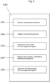
- Fig.3 describes the sequence of a method 100 according to the invention.
- a mass flow of a medium flowing through the pipeline 10 is measured with a Coriolis flow meter 20, wherein the Coriolis flow meter is connected to the pipeline via an inlet 21.1 and an outlet 21.2 of a measuring tube (21),
- Quasistatic means, for example, that a liquid level of the medium or the medium has a speed of movement less than a specified minimum speed of the Coriolis measuring device or with regard to the flow velocity measurement by pressure difference measurement.
- the installation situation of the Coriolis measuring device can be taken into account. For example, if the Coriolis measuring device is arranged vertically or at an angle, a height difference between the pressure sensors leads to a pressure difference, which may also have to be taken into account.
- the time period Z is greater than 2 seconds, and in particular greater than 4 seconds and preferably greater than 5 seconds. In this way, it can be ruled out that a difference in measured values at slow or low flow rates arises, for example, due to a locally different media composition.
- the procedural steps do not have to follow a strict chronological order and can, for example, be carried out at least partially at the same time.
- the numbering introduced essentially serves to identify the procedural steps.
Landscapes
- Physics & Mathematics (AREA)
- Fluid Mechanics (AREA)
- General Physics & Mathematics (AREA)
- Measuring Volume Flow (AREA)
Claims (8)
- Arrangement (1) comprenant :Une conduite (10) ;Un débitmètre Coriolis (20), lequel comprend au moins un tube de mesure (21) avec respectivement une entrée (21.1) et une sortie (21. 2), lequel débitmètre est conçu pour mesurer le débit massique d'un produit s'écoulant à travers la conduite ;un premier capteur de pression (31) étant monté dans ou sur une section d'entrée de la conduite et un deuxième capteur de pression (32) étant monté dans ou sur une section de sortie de la conduite,et/ou un capteur de pression différentielle (33) étant conçu pour mesurer une différence de pression entre une section d'entrée de la conduite et une section de sortie de la conduite,les capteurs de pression et/ou le capteur de pression différentielle étant conçus pour déterminer une vitesse d'écoulement du produit à travers la conduite par détermination d'une pression différentielle entre une section d'entrée de la conduite et une section de sortie de la conduite ;un premier capteur de contrôle (41) étant monté dans ou sur une section d'entrée de la conduite (11) et un deuxième capteur de contrôle (42) étant monté dans ou sur une section de sortie (12) de la conduite,les capteurs de contrôle étant conçus pour surveiller une grandeur de mesure autre que la pression du produit afin de détecter un état statique du produit, un circuit électronique de mesure/d'exploitation (22) du débitmètre Coriolis ou un ordinateur externe étant conçu pour enregistrer et traiter des signaux de mesure des capteurs de contrôle (41, 42), des capteurs de pression (31, 32) et/ou du capteur de pression différentielle (33) et pour fournir une indication concernant la vitesse d'écoulement du produit,caractérisé en ce quele circuit électronique de mesure/d'exploitation (22) du débitmètre Coriolis ou l'ordinateur externe est conçu pour ignorer une mesure de la vitesse d'écoulement par mesure de pression différentielle dans le cas où un état statique ou quasi-statique du produit est détecté au moyen des capteurs de contrôle.
- Arrangement selon la revendication 1,
pour lequel la grandeur de mesure des capteurs de contrôle (41, 42) est au moins l'une des suivantes :
densité du produit, viscosité, vitesse du son, conductivité, capacité thermique, capacité électrique, état physique du produit. - Arrangement selon la revendication 1 ou 2,pour lequel un circuit électronique de mesure/d'exploitation (22) du débitmètre Coriolis est conçu pour enregistrer et traiter des signaux de mesure des capteurs de contrôle (41, 42), des capteurs de pression (31, 32) et/ou du capteur de pression différentielle (33) et pour fournir une indication concernant la vitesse d'écoulement du produit, oupour lequel l'arrangement comporte un ordinateur externe (50), lequel est conçu pour enregistrer et traiter des signaux de mesure des capteurs de contrôle (41, 42), des capteurs de pression (31, 32) et/ou du capteur de pression différentielle (33) ainsi que des valeurs mesurées de débit du circuit électronique de mesure/d'exploitation et pour fournir une indication concernant la vitesse d'écoulement du produit.
- Procédé (100) destiné à l'exploitation de l'arrangement (1) selon l'une des revendications précédentes,
ledit procédé comprenant les étapes suivantes :(101) Mesure d'un débit massique d'un produit s'écoulant dans une conduite (10) avec un débitmètre Coriolis (20), le débitmètre Coriolis étant relié à la conduite par une entrée (21.1) et une sortie (21.2) d'un tube de mesure (21),(102) Mesure d'une pression différentielle du produit entre une section d'entrée de la conduite et une section de sortie de la conduite au moyen d'un premier capteur de pression (31) et d'un deuxième capteur de pression (32) et/ou d'un capteur de pression différentielle (33),(103) Détermination d'une première vitesse d'écoulement du produit à travers la conduite sur la base de la mesure de pression différentielle,(104) Mesure d'une grandeur de mesure concernant le produit autre que la pression du produit avec un premier capteur de contrôle (41) dans ou sur la section côté entrée de la conduite et un deuxième capteur de contrôle (42) dans ou sur la section côté sortie de la conduite,caractérisé en ce quele procédé comprend l'étape suivante :(105) Ignorance de la mesure de la vitesse d'écoulement par mesure de la pression différentielle dans le cas où un état statique ou quasi-statique du produit est détecté au moyen des capteurs de contrôle. - Procédé selon la revendication 4,
pour lequel la détection de l'état statique du produit comprend les étapes suivantes :Génération d'une première courbe de valeurs mesurées (MW1) avec le premier capteur de contrôle (41) et génération d'une deuxième courbe de valeurs mesurées (MW2) avec le deuxième capteur de contrôle (42) ;Interprétation d'une différence de mesure (MD) entre des valeurs mesurées de la première courbe de valeurs mesurées et des valeurs mesurées de la deuxième courbe de valeurs mesurées comme une conséquence d'un état statique du produit, dans le cas où la différence de valeurs mesurées par rapport à une première valeur moyenne des valeurs mesurées associées est supérieure à une première valeur de seuil
et/ouDétermination d'une deuxième vitesse d'écoulement à partir d'une corrélation croisée entre la première courbe de valeurs mesurées et la deuxième courbe de valeurs mesurées et interprétation d'un écart de la deuxième vitesse d'écoulement par rapport à une deuxième valeur moyenne de la première vitesse d'écoulement et de la deuxième vitesse d'écoulement comme une conséquence d'un état statique du produit, dans le cas où l'écart est supérieur à une deuxième valeur de seuil
et/ouInterprétation d'une différence de valeurs mesurées entre les valeurs mesurées de la première courbe de valeurs mesurées et les valeurs mesurées de la deuxième courbe de valeurs mesurées comme une conséquence d'un état statique du produit, dans le cas où la différence de valeurs mesurées est constante sur une période de temps (Z). - Procédé selon la revendication 5,pour lequel la première valeur de seuil est par exemple supérieure à la première valeur moyenne d'au moins 20 %, notamment d'au moins 40 % et de préférence d'au moins 50 %,
et/oupour lequel la deuxième valeur de seuil est par exemple supérieure à la deuxième valeur moyenne d'au moins 20 %, notamment d'au moins 40 % et de préférence d'au moins 50 %. - Procédé selon la revendication 5 ou 6,
pour lequel la période temps (Z) est supérieure à 2 secondes, notamment supérieure à 4 secondes et de préférence supérieure à 5 secondes. - Procédé selon l'une des revendications 4 à 7,
pour lequel un circuit électronique de mesure/d'exploitation (22) du débitmètre Coriolis enregistre et traite des signaux de mesure des capteurs de contrôle (41, 42), des capteurs de pression (31, 32) et/ou du capteur de pression différentielle (33) et fournit une indication concernant la vitesse d'écoulement du produit, ou un ordinateur externe enregistre et traite les signaux de mesure des capteurs de contrôle (41, 42), des capteurs de pression (31, 32) et/ou du capteur de pression différentielle (33) ainsi que les valeurs mesurées de débit du circuit électronique de mesure/d'exploitation et fournit une indication concernant la vitesse d'écoulement du produit.
Applications Claiming Priority (2)
| Application Number | Priority Date | Filing Date | Title |
|---|---|---|---|
| DE102019125682.8A DE102019125682A1 (de) | 2019-09-24 | 2019-09-24 | Anordnung und Verfahren zum Erkennen und Korrigieren einer fehlerhaften Durchflussmessung |
| PCT/EP2020/073412 WO2021058207A1 (fr) | 2019-09-24 | 2020-08-20 | Agencement et procédé d'identification et de correction de mesure de débit volumétrique défectueuse |
Publications (2)
| Publication Number | Publication Date |
|---|---|
| EP4034847A1 EP4034847A1 (fr) | 2022-08-03 |
| EP4034847B1 true EP4034847B1 (fr) | 2024-05-22 |
Family
ID=72178539
Family Applications (1)
| Application Number | Title | Priority Date | Filing Date |
|---|---|---|---|
| EP20760448.9A Active EP4034847B1 (fr) | 2019-09-24 | 2020-08-20 | Agencement et procédé d'identification et de correction de mesure de débit volumétrique défectueuse |
Country Status (5)
| Country | Link |
|---|---|
| US (1) | US12098944B2 (fr) |
| EP (1) | EP4034847B1 (fr) |
| CN (1) | CN114364950B (fr) |
| DE (1) | DE102019125682A1 (fr) |
| WO (1) | WO2021058207A1 (fr) |
Families Citing this family (2)
| Publication number | Priority date | Publication date | Assignee | Title |
|---|---|---|---|---|
| DE102019126883A1 (de) * | 2019-10-07 | 2021-04-08 | Endress+Hauser Flowtec Ag | Verfahren zum Überwachen eines Meßgeräte-Systems |
| US12013273B2 (en) | 2022-02-23 | 2024-06-18 | Saudi Arabian Oil Company | Drilling mud flow metering system and method |
Family Cites Families (10)
| Publication number | Priority date | Publication date | Assignee | Title |
|---|---|---|---|---|
| DE10335665B4 (de) * | 2003-08-04 | 2005-10-27 | Siemens Ag | Massendurchflussmessgerät |
| CN1856697B (zh) * | 2003-09-29 | 2011-09-07 | 微动公司 | 用于确认科里奥利流量计的流量校准因子的方法 |
| DE102005046319A1 (de) * | 2005-09-27 | 2007-03-29 | Endress + Hauser Flowtec Ag | Verfahren zum Messen eines in einer Rohrleitung strömenden Mediums sowie Meßsystem dafür |
| DE102007019689A1 (de) * | 2007-04-24 | 2008-10-30 | Endress + Hauser Flowtec Ag | Vorrichtung zur Bestimmung und/oder Überwachung des Volumen- und/oder Massedurchflusses eines Mediums |
| KR20120102814A (ko) * | 2008-05-01 | 2012-09-18 | 마이크로 모우션, 인코포레이티드 | 유량계 파라미터의 이상으로부터 진단을 하기 위한 방법 |
| CN104729637B (zh) * | 2015-02-03 | 2018-04-27 | 浙江工业大学 | 一种涡轮流量计在线校准系统及校准方法 |
| DE102015120087B4 (de) | 2015-11-19 | 2025-12-24 | Endress + Hauser Flowtec Ag | Coriolis-Durchfluss- und/oder Coriolis-Dichtemessgerät mit einem Messaufnehmer vom Vibrationstyp und Verwendung des Coriolis-Durchfluss- und/oder Coriolis-Dichtemessgerätes |
| EP3601963B1 (fr) * | 2017-03-20 | 2023-04-26 | Micro Motion, Inc. | Détermination d'un décalage de zéro d'un appareil de mesure vibratoire dans une condition de process |
| DE102017130970B4 (de) * | 2017-12-21 | 2020-01-02 | Endress+Hauser Flowtec Ag | Verfahren zur Erkennung eines Messfehlers bei einer Messung einer Medieneigenschaft eines Mediums mittels eines Feldgeräts der Mess- und Automatisierungstechnik und ein Ultraschall-Durchflussmessgerät oder Ultraschall-Füllstandsmessgerät eingesetzt zur Umsetzung des Verfahrens |
| DE102018102631A1 (de) * | 2018-02-06 | 2019-08-08 | Endress+Hauser Flowtec Ag | Erkennung von Luft in Dampfleitungen |
-
2019
- 2019-09-24 DE DE102019125682.8A patent/DE102019125682A1/de not_active Ceased
-
2020
- 2020-08-20 WO PCT/EP2020/073412 patent/WO2021058207A1/fr not_active Ceased
- 2020-08-20 EP EP20760448.9A patent/EP4034847B1/fr active Active
- 2020-08-20 US US17/754,074 patent/US12098944B2/en active Active
- 2020-08-20 CN CN202080063479.7A patent/CN114364950B/zh active Active
Also Published As
| Publication number | Publication date |
|---|---|
| DE102019125682A1 (de) | 2021-03-25 |
| EP4034847A1 (fr) | 2022-08-03 |
| CN114364950B (zh) | 2026-02-03 |
| WO2021058207A1 (fr) | 2021-04-01 |
| US12098944B2 (en) | 2024-09-24 |
| US20220333971A1 (en) | 2022-10-20 |
| CN114364950A (zh) | 2022-04-15 |
Similar Documents
| Publication | Publication Date | Title |
|---|---|---|
| EP2853683B1 (fr) | Analyse d'un fluide multiphasique | |
| EP3234548B1 (fr) | Ensemble de mesure et procédé de mesure de la densité de milieux coulants | |
| EP3325923B1 (fr) | Débitmètre selon le principe de comptage de tourbillons | |
| DE102008037389A1 (de) | Thermisches Strömungsmesssystem und Verfahren | |
| EP2936082B1 (fr) | Débitmètre a vortex et procédé de mesure du taux de vide d'un écoulement multiphasique | |
| WO2016096296A1 (fr) | Ensemble de mesure de débit selon le principe de différence de pression | |
| WO2015036188A1 (fr) | Dispositif de mesure de pression différentielle comportant des conduits de pression différentielle et procédé de détection de conduits de pression différentielle obstrués | |
| DE102018101923A1 (de) | Verfahren zum Feststellen von Belagsbildung in einem Messrohr und Messgerät zur Durchführung des Verfahrens | |
| EP4034847B1 (fr) | Agencement et procédé d'identification et de correction de mesure de débit volumétrique défectueuse | |
| DE102016113200B4 (de) | Verfahren zum Betreiben eines Durchflussmessgeräts und Durchflussmessgerät | |
| WO2017102218A1 (fr) | Procédé de correction en fonction du nombre de reynolds d'une mesure de débit à l'aide d'un débitmètre à effet coriolis | |
| DE102010030952B4 (de) | Vorrichtung zur Bestimmung und/oder Überwachung eines Volumendurchflusses und/oder einer Durchflussgeschwindigkeit | |
| EP4042111B1 (fr) | Procédé de surveillance d'un système de dispositif de mesure | |
| EP3350567B1 (fr) | Procédé et dispositif de mesure pour la détermination de la compressibilité d'un fluide en écoulement | |
| EP3199927B1 (fr) | Procédé et système permettant de mesurer l'écoulement à travers un conduit de fluide | |
| DE102010006429A1 (de) | Coriolis-Massendurchflussmessgerät und Verfahren zum Betreiben eines Coriolis-Massendurchflussmessgeräts | |
| EP2936085A1 (fr) | Appareil de mesure d'écoulements turbulents et procédé de mesure de la qualité de ses conditions de fonctionnement et de montage | |
| DE102013109128A1 (de) | Hydrostatisches Grenzschichtmessgerät | |
| DE102011050716B4 (de) | Verfahren und Vorrichtung zur Online-Messung der Viskosität eines Fluids | |
| WO2019121105A1 (fr) | Procédé de détection d'une erreur de mesure pendant la mesure d'une propriété de milieu d'un milieu au moyen d'un dispositif de terrain de la téchnique de mesure et d'automatisation et d'un débitmètre à ultrasons ou d'un appareil de mesure de niveau de remplissage à ultrasons utilisés pour l'exécution de ce procédé | |
| EP3729012B1 (fr) | Procédé servant à définir un débit volumique et/ou massique | |
| EP4078096A1 (fr) | Procédé de fonctionnement d'un point de mesure de débit pour des milieux présentant au moins une phase liquide | |
| DE102013114424B4 (de) | Thermischer Durchflusssensor und Verfahren zur Bestimmung eines Volumenstroms | |
| DE102007061585A1 (de) | Verfahren und Einrichtung zum Kompensieren von die Messgenauigkeit störenden Druckeinflüssen bei Coriolis-Durchflussmessgeräten | |
| WO2016062443A1 (fr) | Débitmètre thermique |
Legal Events
| Date | Code | Title | Description |
|---|---|---|---|
| STAA | Information on the status of an ep patent application or granted ep patent |
Free format text: STATUS: UNKNOWN |
|
| STAA | Information on the status of an ep patent application or granted ep patent |
Free format text: STATUS: THE INTERNATIONAL PUBLICATION HAS BEEN MADE |
|
| PUAI | Public reference made under article 153(3) epc to a published international application that has entered the european phase |
Free format text: ORIGINAL CODE: 0009012 |
|
| STAA | Information on the status of an ep patent application or granted ep patent |
Free format text: STATUS: REQUEST FOR EXAMINATION WAS MADE |
|
| 17P | Request for examination filed |
Effective date: 20220221 |
|
| AK | Designated contracting states |
Kind code of ref document: A1 Designated state(s): AL AT BE BG CH CY CZ DE DK EE ES FI FR GB GR HR HU IE IS IT LI LT LU LV MC MK MT NL NO PL PT RO RS SE SI SK SM TR |
|
| DAV | Request for validation of the european patent (deleted) | ||
| DAX | Request for extension of the european patent (deleted) | ||
| REG | Reference to a national code |
Ref country code: DE Ref legal event code: R079 Free format text: PREVIOUS MAIN CLASS: G01F0025000000 Ipc: G01F0001840000 Ref document number: 502020008082 Country of ref document: DE |
|
| GRAP | Despatch of communication of intention to grant a patent |
Free format text: ORIGINAL CODE: EPIDOSNIGR1 |
|
| STAA | Information on the status of an ep patent application or granted ep patent |
Free format text: STATUS: GRANT OF PATENT IS INTENDED |
|
| RIC1 | Information provided on ipc code assigned before grant |
Ipc: G01F 1/74 20060101ALN20231130BHEP Ipc: G01F 7/00 20060101ALN20231130BHEP Ipc: G01F 1/36 20060101ALI20231130BHEP Ipc: G01F 25/10 20220101ALI20231130BHEP Ipc: G01F 1/84 20060101AFI20231130BHEP |
|
| INTG | Intention to grant announced |
Effective date: 20240105 |
|
| GRAS | Grant fee paid |
Free format text: ORIGINAL CODE: EPIDOSNIGR3 |
|
| GRAA | (expected) grant |
Free format text: ORIGINAL CODE: 0009210 |
|
| STAA | Information on the status of an ep patent application or granted ep patent |
Free format text: STATUS: THE PATENT HAS BEEN GRANTED |
|
| AK | Designated contracting states |
Kind code of ref document: B1 Designated state(s): AL AT BE BG CH CY CZ DE DK EE ES FI FR GB GR HR HU IE IS IT LI LT LU LV MC MK MT NL NO PL PT RO RS SE SI SK SM TR |
|
| REG | Reference to a national code |
Ref country code: GB Ref legal event code: FG4D Free format text: NOT ENGLISH |
|
| REG | Reference to a national code |
Ref country code: CH Ref legal event code: EP |
|
| REG | Reference to a national code |
Ref country code: DE Ref legal event code: R096 Ref document number: 502020008082 Country of ref document: DE |
|
| REG | Reference to a national code |
Ref country code: IE Ref legal event code: FG4D Free format text: LANGUAGE OF EP DOCUMENT: GERMAN |
|
| P01 | Opt-out of the competence of the unified patent court (upc) registered |
Free format text: CASE NUMBER: APP_41412/2024 Effective date: 20240712 |
|
| REG | Reference to a national code |
Ref country code: NL Ref legal event code: FP |
|
| REG | Reference to a national code |
Ref country code: LT Ref legal event code: MG9D |
|
| PG25 | Lapsed in a contracting state [announced via postgrant information from national office to epo] |
Ref country code: IS Free format text: LAPSE BECAUSE OF FAILURE TO SUBMIT A TRANSLATION OF THE DESCRIPTION OR TO PAY THE FEE WITHIN THE PRESCRIBED TIME-LIMIT Effective date: 20240922 |
|
| PG25 | Lapsed in a contracting state [announced via postgrant information from national office to epo] |
Ref country code: BG Free format text: LAPSE BECAUSE OF FAILURE TO SUBMIT A TRANSLATION OF THE DESCRIPTION OR TO PAY THE FEE WITHIN THE PRESCRIBED TIME-LIMIT Effective date: 20240522 |
|
| PG25 | Lapsed in a contracting state [announced via postgrant information from national office to epo] |
Ref country code: FI Free format text: LAPSE BECAUSE OF FAILURE TO SUBMIT A TRANSLATION OF THE DESCRIPTION OR TO PAY THE FEE WITHIN THE PRESCRIBED TIME-LIMIT Effective date: 20240522 Ref country code: HR Free format text: LAPSE BECAUSE OF FAILURE TO SUBMIT A TRANSLATION OF THE DESCRIPTION OR TO PAY THE FEE WITHIN THE PRESCRIBED TIME-LIMIT Effective date: 20240522 |
|
| PG25 | Lapsed in a contracting state [announced via postgrant information from national office to epo] |
Ref country code: GR Free format text: LAPSE BECAUSE OF FAILURE TO SUBMIT A TRANSLATION OF THE DESCRIPTION OR TO PAY THE FEE WITHIN THE PRESCRIBED TIME-LIMIT Effective date: 20240823 |
|
| PG25 | Lapsed in a contracting state [announced via postgrant information from national office to epo] |
Ref country code: PT Free format text: LAPSE BECAUSE OF FAILURE TO SUBMIT A TRANSLATION OF THE DESCRIPTION OR TO PAY THE FEE WITHIN THE PRESCRIBED TIME-LIMIT Effective date: 20240923 |
|
| PG25 | Lapsed in a contracting state [announced via postgrant information from national office to epo] |
Ref country code: ES Free format text: LAPSE BECAUSE OF FAILURE TO SUBMIT A TRANSLATION OF THE DESCRIPTION OR TO PAY THE FEE WITHIN THE PRESCRIBED TIME-LIMIT Effective date: 20240522 |
|
| PG25 | Lapsed in a contracting state [announced via postgrant information from national office to epo] |
Ref country code: PL Free format text: LAPSE BECAUSE OF FAILURE TO SUBMIT A TRANSLATION OF THE DESCRIPTION OR TO PAY THE FEE WITHIN THE PRESCRIBED TIME-LIMIT Effective date: 20240522 |
|
| PG25 | Lapsed in a contracting state [announced via postgrant information from national office to epo] |
Ref country code: LV Free format text: LAPSE BECAUSE OF FAILURE TO SUBMIT A TRANSLATION OF THE DESCRIPTION OR TO PAY THE FEE WITHIN THE PRESCRIBED TIME-LIMIT Effective date: 20240522 |
|
| PG25 | Lapsed in a contracting state [announced via postgrant information from national office to epo] |
Ref country code: PT Free format text: LAPSE BECAUSE OF FAILURE TO SUBMIT A TRANSLATION OF THE DESCRIPTION OR TO PAY THE FEE WITHIN THE PRESCRIBED TIME-LIMIT Effective date: 20240923 Ref country code: PL Free format text: LAPSE BECAUSE OF FAILURE TO SUBMIT A TRANSLATION OF THE DESCRIPTION OR TO PAY THE FEE WITHIN THE PRESCRIBED TIME-LIMIT Effective date: 20240522 Ref country code: NO Free format text: LAPSE BECAUSE OF FAILURE TO SUBMIT A TRANSLATION OF THE DESCRIPTION OR TO PAY THE FEE WITHIN THE PRESCRIBED TIME-LIMIT Effective date: 20240822 Ref country code: LV Free format text: LAPSE BECAUSE OF FAILURE TO SUBMIT A TRANSLATION OF THE DESCRIPTION OR TO PAY THE FEE WITHIN THE PRESCRIBED TIME-LIMIT Effective date: 20240522 Ref country code: IS Free format text: LAPSE BECAUSE OF FAILURE TO SUBMIT A TRANSLATION OF THE DESCRIPTION OR TO PAY THE FEE WITHIN THE PRESCRIBED TIME-LIMIT Effective date: 20240922 Ref country code: HR Free format text: LAPSE BECAUSE OF FAILURE TO SUBMIT A TRANSLATION OF THE DESCRIPTION OR TO PAY THE FEE WITHIN THE PRESCRIBED TIME-LIMIT Effective date: 20240522 Ref country code: GR Free format text: LAPSE BECAUSE OF FAILURE TO SUBMIT A TRANSLATION OF THE DESCRIPTION OR TO PAY THE FEE WITHIN THE PRESCRIBED TIME-LIMIT Effective date: 20240823 Ref country code: FI Free format text: LAPSE BECAUSE OF FAILURE TO SUBMIT A TRANSLATION OF THE DESCRIPTION OR TO PAY THE FEE WITHIN THE PRESCRIBED TIME-LIMIT Effective date: 20240522 Ref country code: ES Free format text: LAPSE BECAUSE OF FAILURE TO SUBMIT A TRANSLATION OF THE DESCRIPTION OR TO PAY THE FEE WITHIN THE PRESCRIBED TIME-LIMIT Effective date: 20240522 Ref country code: BG Free format text: LAPSE BECAUSE OF FAILURE TO SUBMIT A TRANSLATION OF THE DESCRIPTION OR TO PAY THE FEE WITHIN THE PRESCRIBED TIME-LIMIT Effective date: 20240522 Ref country code: RS Free format text: LAPSE BECAUSE OF FAILURE TO SUBMIT A TRANSLATION OF THE DESCRIPTION OR TO PAY THE FEE WITHIN THE PRESCRIBED TIME-LIMIT Effective date: 20240822 |
|
| PG25 | Lapsed in a contracting state [announced via postgrant information from national office to epo] |
Ref country code: DK Free format text: LAPSE BECAUSE OF FAILURE TO SUBMIT A TRANSLATION OF THE DESCRIPTION OR TO PAY THE FEE WITHIN THE PRESCRIBED TIME-LIMIT Effective date: 20240522 |
|
| PG25 | Lapsed in a contracting state [announced via postgrant information from national office to epo] |
Ref country code: EE Free format text: LAPSE BECAUSE OF FAILURE TO SUBMIT A TRANSLATION OF THE DESCRIPTION OR TO PAY THE FEE WITHIN THE PRESCRIBED TIME-LIMIT Effective date: 20240522 |
|
| PG25 | Lapsed in a contracting state [announced via postgrant information from national office to epo] |
Ref country code: CZ Free format text: LAPSE BECAUSE OF FAILURE TO SUBMIT A TRANSLATION OF THE DESCRIPTION OR TO PAY THE FEE WITHIN THE PRESCRIBED TIME-LIMIT Effective date: 20240522 |
|
| PG25 | Lapsed in a contracting state [announced via postgrant information from national office to epo] |
Ref country code: SK Free format text: LAPSE BECAUSE OF FAILURE TO SUBMIT A TRANSLATION OF THE DESCRIPTION OR TO PAY THE FEE WITHIN THE PRESCRIBED TIME-LIMIT Effective date: 20240522 Ref country code: RO Free format text: LAPSE BECAUSE OF FAILURE TO SUBMIT A TRANSLATION OF THE DESCRIPTION OR TO PAY THE FEE WITHIN THE PRESCRIBED TIME-LIMIT Effective date: 20240522 |
|
| PG25 | Lapsed in a contracting state [announced via postgrant information from national office to epo] |
Ref country code: SM Free format text: LAPSE BECAUSE OF FAILURE TO SUBMIT A TRANSLATION OF THE DESCRIPTION OR TO PAY THE FEE WITHIN THE PRESCRIBED TIME-LIMIT Effective date: 20240522 |
|
| PG25 | Lapsed in a contracting state [announced via postgrant information from national office to epo] |
Ref country code: SM Free format text: LAPSE BECAUSE OF FAILURE TO SUBMIT A TRANSLATION OF THE DESCRIPTION OR TO PAY THE FEE WITHIN THE PRESCRIBED TIME-LIMIT Effective date: 20240522 Ref country code: SK Free format text: LAPSE BECAUSE OF FAILURE TO SUBMIT A TRANSLATION OF THE DESCRIPTION OR TO PAY THE FEE WITHIN THE PRESCRIBED TIME-LIMIT Effective date: 20240522 Ref country code: RO Free format text: LAPSE BECAUSE OF FAILURE TO SUBMIT A TRANSLATION OF THE DESCRIPTION OR TO PAY THE FEE WITHIN THE PRESCRIBED TIME-LIMIT Effective date: 20240522 Ref country code: EE Free format text: LAPSE BECAUSE OF FAILURE TO SUBMIT A TRANSLATION OF THE DESCRIPTION OR TO PAY THE FEE WITHIN THE PRESCRIBED TIME-LIMIT Effective date: 20240522 Ref country code: DK Free format text: LAPSE BECAUSE OF FAILURE TO SUBMIT A TRANSLATION OF THE DESCRIPTION OR TO PAY THE FEE WITHIN THE PRESCRIBED TIME-LIMIT Effective date: 20240522 Ref country code: CZ Free format text: LAPSE BECAUSE OF FAILURE TO SUBMIT A TRANSLATION OF THE DESCRIPTION OR TO PAY THE FEE WITHIN THE PRESCRIBED TIME-LIMIT Effective date: 20240522 |
|
| PG25 | Lapsed in a contracting state [announced via postgrant information from national office to epo] |
Ref country code: IT Free format text: LAPSE BECAUSE OF FAILURE TO SUBMIT A TRANSLATION OF THE DESCRIPTION OR TO PAY THE FEE WITHIN THE PRESCRIBED TIME-LIMIT Effective date: 20240522 |
|
| REG | Reference to a national code |
Ref country code: DE Ref legal event code: R097 Ref document number: 502020008082 Country of ref document: DE |
|
| PLBE | No opposition filed within time limit |
Free format text: ORIGINAL CODE: 0009261 |
|
| STAA | Information on the status of an ep patent application or granted ep patent |
Free format text: STATUS: NO OPPOSITION FILED WITHIN TIME LIMIT |
|
| REG | Reference to a national code |
Ref country code: CH Ref legal event code: PL |
|
| PG25 | Lapsed in a contracting state [announced via postgrant information from national office to epo] |
Ref country code: LU Free format text: LAPSE BECAUSE OF NON-PAYMENT OF DUE FEES Effective date: 20240820 |
|
| PG25 | Lapsed in a contracting state [announced via postgrant information from national office to epo] |
Ref country code: SI Free format text: LAPSE BECAUSE OF FAILURE TO SUBMIT A TRANSLATION OF THE DESCRIPTION OR TO PAY THE FEE WITHIN THE PRESCRIBED TIME-LIMIT Effective date: 20240522 Ref country code: MC Free format text: LAPSE BECAUSE OF FAILURE TO SUBMIT A TRANSLATION OF THE DESCRIPTION OR TO PAY THE FEE WITHIN THE PRESCRIBED TIME-LIMIT Effective date: 20240522 Ref country code: CH Free format text: LAPSE BECAUSE OF NON-PAYMENT OF DUE FEES Effective date: 20240831 |
|
| 26N | No opposition filed |
Effective date: 20250225 |
|
| REG | Reference to a national code |
Ref country code: BE Ref legal event code: MM Effective date: 20240831 |
|
| PG25 | Lapsed in a contracting state [announced via postgrant information from national office to epo] |
Ref country code: BE Free format text: LAPSE BECAUSE OF NON-PAYMENT OF DUE FEES Effective date: 20240831 |
|
| PG25 | Lapsed in a contracting state [announced via postgrant information from national office to epo] |
Ref country code: IE Free format text: LAPSE BECAUSE OF NON-PAYMENT OF DUE FEES Effective date: 20240820 |
|
| PG25 | Lapsed in a contracting state [announced via postgrant information from national office to epo] |
Ref country code: SE Free format text: LAPSE BECAUSE OF FAILURE TO SUBMIT A TRANSLATION OF THE DESCRIPTION OR TO PAY THE FEE WITHIN THE PRESCRIBED TIME-LIMIT Effective date: 20240522 |
|
| PGFP | Annual fee paid to national office [announced via postgrant information from national office to epo] |
Ref country code: NL Payment date: 20250821 Year of fee payment: 6 |
|
| PGFP | Annual fee paid to national office [announced via postgrant information from national office to epo] |
Ref country code: DE Payment date: 20250820 Year of fee payment: 6 |
|
| PGFP | Annual fee paid to national office [announced via postgrant information from national office to epo] |
Ref country code: GB Payment date: 20250820 Year of fee payment: 6 |
|
| PGFP | Annual fee paid to national office [announced via postgrant information from national office to epo] |
Ref country code: AT Payment date: 20251020 Year of fee payment: 5 Ref country code: FR Payment date: 20250828 Year of fee payment: 6 |
|
| PG25 | Lapsed in a contracting state [announced via postgrant information from national office to epo] |
Ref country code: CY Free format text: LAPSE BECAUSE OF FAILURE TO SUBMIT A TRANSLATION OF THE DESCRIPTION OR TO PAY THE FEE WITHIN THE PRESCRIBED TIME-LIMIT; INVALID AB INITIO Effective date: 20200820 |
|
| PG25 | Lapsed in a contracting state [announced via postgrant information from national office to epo] |
Ref country code: HU Free format text: LAPSE BECAUSE OF FAILURE TO SUBMIT A TRANSLATION OF THE DESCRIPTION OR TO PAY THE FEE WITHIN THE PRESCRIBED TIME-LIMIT; INVALID AB INITIO Effective date: 20200820 |