EP3351077A1 - Dispositif de génération d'itinéraire et programme de génération d'itinéraire - Google Patents
Dispositif de génération d'itinéraire et programme de génération d'itinéraire Download PDFInfo
- Publication number
- EP3351077A1 EP3351077A1 EP17001059.9A EP17001059A EP3351077A1 EP 3351077 A1 EP3351077 A1 EP 3351077A1 EP 17001059 A EP17001059 A EP 17001059A EP 3351077 A1 EP3351077 A1 EP 3351077A1
- Authority
- EP
- European Patent Office
- Prior art keywords
- point
- work
- travel route
- shape
- entrance passage
- Prior art date
- Legal status (The legal status is an assumption and is not a legal conclusion. Google has not performed a legal analysis and makes no representation as to the accuracy of the status listed.)
- Granted
Links
Images

Classifications
-
- G—PHYSICS
- G05—CONTROLLING; REGULATING
- G05D—SYSTEMS FOR CONTROLLING OR REGULATING NON-ELECTRIC VARIABLES
- G05D1/00—Control of position, course, altitude or attitude of land, water, air or space vehicles, e.g. using automatic pilots
- G05D1/02—Control of position or course in two dimensions
- G05D1/021—Control of position or course in two dimensions specially adapted to land vehicles
- G05D1/0259—Control of position or course in two dimensions specially adapted to land vehicles using magnetic or electromagnetic means
-
- G—PHYSICS
- G05—CONTROLLING; REGULATING
- G05D—SYSTEMS FOR CONTROLLING OR REGULATING NON-ELECTRIC VARIABLES
- G05D1/00—Control of position, course, altitude or attitude of land, water, air or space vehicles, e.g. using automatic pilots
- G05D1/40—Control within particular dimensions
- G05D1/43—Control of position or course in two dimensions [2D]
-
- A—HUMAN NECESSITIES
- A01—AGRICULTURE; FORESTRY; ANIMAL HUSBANDRY; HUNTING; TRAPPING; FISHING
- A01B—SOIL WORKING IN AGRICULTURE OR FORESTRY; PARTS, DETAILS, OR ACCESSORIES OF AGRICULTURAL MACHINES OR IMPLEMENTS, IN GENERAL
- A01B69/00—Steering of agricultural machines or implements; Guiding agricultural machines or implements on a desired track
- A01B69/007—Steering or guiding of agricultural vehicles, e.g. steering of the tractor to keep the plough in the furrow
- A01B69/008—Steering or guiding of agricultural vehicles, e.g. steering of the tractor to keep the plough in the furrow automatic
-
- G—PHYSICS
- G05—CONTROLLING; REGULATING
- G05D—SYSTEMS FOR CONTROLLING OR REGULATING NON-ELECTRIC VARIABLES
- G05D1/00—Control of position, course, altitude or attitude of land, water, air or space vehicles, e.g. using automatic pilots
- G05D1/02—Control of position or course in two dimensions
- G05D1/021—Control of position or course in two dimensions specially adapted to land vehicles
- G05D1/0276—Control of position or course in two dimensions specially adapted to land vehicles using signals provided by a source external to the vehicle
- G05D1/0278—Control of position or course in two dimensions specially adapted to land vehicles using signals provided by a source external to the vehicle using satellite positioning signals, e.g. GPS
-
- G—PHYSICS
- G05—CONTROLLING; REGULATING
- G05D—SYSTEMS FOR CONTROLLING OR REGULATING NON-ELECTRIC VARIABLES
- G05D1/00—Control of position, course, altitude or attitude of land, water, air or space vehicles, e.g. using automatic pilots
- G05D1/02—Control of position or course in two dimensions
- G05D1/021—Control of position or course in two dimensions specially adapted to land vehicles
- G05D1/0276—Control of position or course in two dimensions specially adapted to land vehicles using signals provided by a source external to the vehicle
- G05D1/0285—Control of position or course in two dimensions specially adapted to land vehicles using signals provided by a source external to the vehicle using signals transmitted via a public communication network, e.g. GSM network
-
- A—HUMAN NECESSITIES
- A01—AGRICULTURE; FORESTRY; ANIMAL HUSBANDRY; HUNTING; TRAPPING; FISHING
- A01B—SOIL WORKING IN AGRICULTURE OR FORESTRY; PARTS, DETAILS, OR ACCESSORIES OF AGRICULTURAL MACHINES OR IMPLEMENTS, IN GENERAL
- A01B79/00—Methods for working soil
- A01B79/005—Precision agriculture
-
- G—PHYSICS
- G05—CONTROLLING; REGULATING
- G05D—SYSTEMS FOR CONTROLLING OR REGULATING NON-ELECTRIC VARIABLES
- G05D2111/00—Details of signals used for control of position, course, altitude or attitude of land, water, air or space vehicles
- G05D2111/50—Internal signals, i.e. from sensors located in the vehicle, e.g. from compasses or angular sensors
- G05D2111/52—Internal signals, i.e. from sensors located in the vehicle, e.g. from compasses or angular sensors generated by inertial navigation means, e.g. gyroscopes or accelerometers
-
- Y—GENERAL TAGGING OF NEW TECHNOLOGICAL DEVELOPMENTS; GENERAL TAGGING OF CROSS-SECTIONAL TECHNOLOGIES SPANNING OVER SEVERAL SECTIONS OF THE IPC; TECHNICAL SUBJECTS COVERED BY FORMER USPC CROSS-REFERENCE ART COLLECTIONS [XRACs] AND DIGESTS
- Y02—TECHNOLOGIES OR APPLICATIONS FOR MITIGATION OR ADAPTATION AGAINST CLIMATE CHANGE
- Y02A—TECHNOLOGIES FOR ADAPTATION TO CLIMATE CHANGE
- Y02A40/00—Adaptation technologies in agriculture, forestry, livestock or agroalimentary production
- Y02A40/10—Adaptation technologies in agriculture, forestry, livestock or agroalimentary production in agriculture
- Y02A40/22—Improving land use; Improving water use or availability; Controlling erosion
Definitions
- the present invention relates to a travel route generation device and a travel route generation program that generate a travel route for a work vehicle that automatically travels in a work field.
- JP 2016-31649 A discloses teaching travel by which a manually operated tractor travels within a field to acquire external shape data of the field from a locus of the travel.
- a procedure of the teaching travel is as follows:
- the travel route for the tractor to automatically travel in a central work field positioned inside a headland is generated using the work field shape calculated in this way.
- a work field such as a field may be divided by a boundary, such as a ridge, and an entrance passage for the work vehicle to enter and leave the work field may be determined for each work field.
- This entrance passage may be an inclined passage or a firmly hardened passage, and thus may be a region in which the work vehicle does not perform work.
- existence of this entrance passage is neglected. Therefore, the travel route for automatic travel generated for the calculated work field shape may overlap with the entrance passage.
- a problem may also arise that a work region that is not covered by the travel route will be left because the travel route is set at a position distant from the entrance passage in order to avoid the travel route and the entrance passage overlapping each other.
- an object of the present invention is to provide a travel route generation device and a travel route generation program capable of easily and accurately calculating a target work region for automatic travel in the work field.
- a travel route generation device may be for a work vehicle that enters and leaves a work field divided by a boundary through an entrance passage.
- the travel route generation device may include: a starting point registration unit that is configured to position-register a first endpoint on a side of the boundary of the entrance passage as a starting point; an intermediate point registration unit that is configured to position-register a shape feature point that prescribes a shape of the work field as an intermediate point; an end point registration unit that is configured to position-register a second endpoint facing the first endpoint on a side of the boundary of the entrance passage as an end point; a basic shape calculation unit that is configured to calculate a basic shape of the work field by connecting a position of the starting point, a position of the intermediate point, and a position of the end point; an entrance passage information generation unit that is configured to generate entrance passage information with a quadrangle as a shape of the entrance passage, the quadrangle having the starting point and the end point as opposite vertices and having two sides
- geometrical shapes used in the present disclosure are not used in order to identify a geometrically strict shape, but are used in order to describe such a shape that can generally be seen or understood as being almost a corresponding geometrical shape as a whole. Therefore, each side of a polygon is not always a straight line and may be (slightly) bended and/or uneven.
- position-register may be understood as to identify and/or register a position of a point.
- the travel route generation device may, for example, store information indicating the position of the point in a storage device.
- This configuration may allow calculation of the basic shape of the work field by connecting the position of the starting point, the position of the intermediate point, and the position of the end point acquired in movement along the boundary of the work field that leaves one end of the entrance passage and returns to the other end of the entrance passage.
- the work field may be regarded as a polygon and the intermediate point may correspond to a polygon vertex, which may be a feature point of the shape.
- the number of intermediate points is one
- the work field is a quadrangle
- the number of intermediate points is two
- the work field is a pentagon the number of intermediate points is three.
- the entrance passage can be regarded as a quadrangle that is substantially a rectangle.
- the shape of the rectangle indicating the entrance passage can be calculated.
- the basic shape of the work field may be a polygon in which a small rectangle (e.g. quadrangle) is interposed at a place corresponding to the entrance passage. Therefore, the target work region in which the work vehicle needs to work may be obtained by removing the rectangle indicating the entrance passage from the calculated work field shape.
- the travel route generation unit may generate the travel route that covers this target work region, thereby providing the travel route that causes neither problem that the travel route and the entrance passage overlap each other nor problem that the travel route is distant from the entrance passage.
- the entrance passage may be inclined in the work field such as a field, it may be important that travel of the work vehicle that enters the target work region from the entrance passage is straight movement and that travel of the work vehicle immediately before leaving the target work region for the entrance passage is straight movement. Accordingly, it may be important to consider a travel direction of the work vehicle in the entrance passage as one of conditions of travel route generation. Therefore, it may be advantageous when the travel direction in the entrance passage is also calculated in addition to the shape of the entrance passage.
- the entrance passage information generation unit may be configured to define vertices other than the starting point and the end point of the quadrangle representing the shape of the entrance passage as an inner point that is adjacent to the target work region and an outer point distant from the target work region, and a direction from a side connecting the outer point and the end point to a side connecting the starting point and the inner point may be an entry direction of the work vehicle into the target work region.
- an inner point registration unit may be provided that is configured to define vertices other than the starting point and the end point of the quadrangle representing the shape of the entrance passage as an inner point that is adjacent to the target work region and an outer point distant from the target work region, and to register the inner point. Employing the inner point registered as an actual position may allow more accurate calculation of the shape of the entrance passage.
- Position coordinates needed for position-registration of the starting point, the intermediate point, and the end point may be a work field coordinate system or a latitude longitude system.
- a satellite positioning module may be mounted on the work vehicle that travels automatically, and it may be advantageous to use this satellite positioning module. Therefore, in some examples, position-registration of the starting point, the intermediate point, and the end point may be performed through traveling of the work vehicle along the boundary, and the positions of the starting point, the intermediate point, and the end point may be calculated using an own position based on positioning data from a satellite positioning module mounted on the work vehicle.
- a position detecting system using the satellite positioning module mounted on the work vehicle may be used, which may be advantageous in terms of cost as well.
- the travel route generation device may be configured such that one or more aiming points associated with the positions of the starting point, the intermediate point, and the end point are prescribed at corners of the work vehicle, and the positions of the starting point, the intermediate point, and the end point are calculated by modifying the own position according to distances from the own position to the aiming points. This may enable the work vehicle to measure the positions accurately only by causing an appropriate corner (e.g.
- aiming point of the work vehicle to approach the shape feature point of the work field.
- setting such aiming points at a front right end, front left end, rear right end, and rear left end of the work vehicle and selecting one of the four ends may allow the aiming point to smoothly match the shape feature point of the work field.
- one of the aiming points may be selected by a user and the selected aiming point may be used for calculating a position of one or more of: the starting point, the intermediate point, the end point.
- a travel route generation device configured to calculate a shape of an arbitrary region in the work field as the target work region and generate the travel route independently of the entrance.
- a travel route generation device for a work vehicle may include: a starting point registration unit that is configured to position-register a first endpoint of a target work region for work travel as a starting point; an intermediate point registration unit that is configured to position-register a shape feature point that prescribes a shape of the target work region as an intermediate point; an end point registration unit that is configured to position-register the first endpoint or a second endpoint adjacent to the first endpoint as an end point; a basic shape calculation unit that is configured to calculate a basic shape of the target work region by connecting a position of the starting point, a position of the intermediate point, and a position of the end point; and a travel route generation unit that is configured to generate a travel route for the work vehicle to automatically travel in the target work region, wherein one or more aiming points associated with the positions of the starting
- This travel route generation device which may use the work vehicle or a vehicle capable of traveling in the target work region as a position measuring instrument, can calculate the shape smoothly even if the target work region is vast.
- one of the aiming points may be selected by a user and the selected aiming point may be used for calculating a position of one or more of: the starting point, the intermediate point, the end point.
- a computer program product for travel route generation is provided for a work vehicle that enters and leaves a work field divided by a boundary through an entrance passage.
- the computer program product may cause a computer to execute: a starting point registration function of position-registering a first endpoint on a side of the boundary of the entrance passage as a starting point; an intermediate point registration function of position-registering a shape feature point that prescribes a shape of the work field as an intermediate point; an end point registration function of position-registering a second endpoint facing the first endpoint on a side of the boundary of the entrance passage as an end point; a basic shape calculation function of calculating a basic shape of the work field by connecting a position of the starting point, a position of the intermediate point, and a position of the end point; an entrance passage information generation function of generating entrance passage information with a quadrangle as a shape of the entrance passage, the quadrangle having the starting point and the end point as opposite vertices and having two sides along an external shape extension line of the basic shape; and a travel route generation function of defining a region other than the entrance passage of the work field as a target work region, and generating a travel route for the work vehicle to automatically
- a "function" of a computer program product may be understood as indicating a group of computer-readable instructions that, when loaded and run on a computer, cause the computer to execute one or more process steps defined by the instructions. Accordingly, in various embodiments and examples described herein, the term “function” is not limited to a function, module, class, method or the like of any specific programming language.
- a computer program product for travel route generation may cause a computer to calculate a shape of an arbitrary region in the work field as a target work region and generates a travel route independently of the entrance.
- This computer program product for travel route generation for a work vehicle may cause a computer to execute: a starting point registration function of position-registering a first endpoint of a target work region for work travel as a starting point; an intermediate point registration function of position-registering a shape feature point that prescribes a shape of the target work region as an intermediate point; an end point registration function of position-registering the first endpoint or a second endpoint adjacent to the first endpoint as an end point; a basic shape calculation function of calculating a basic shape of the target work region by connecting a position of the starting point, a position of the intermediate point, and a position of the end point; a travel route generation function of generating a travel route for the work vehicle to automatically travel in the target work region; and a function of calculating the positions of the starting point,
- a computer implemented method for travel route generation for a work vehicle that enters and leaves a work field divided by a boundary through an entrance passage.
- the method may comprise the following:
- a computer-implemented method for travel route generation for a work vehicle may comprise the following:
- the subject matter described in the application can be implemented as a method or as a system, possibly in the form of one or more computer program products.
- the subject matter described in the application can be implemented in a data signal or on a machine readable medium, where the medium is embodied in one or more information carriers, such as a CD-ROM, a DVD-ROM, a semiconductor memory, or a hard disk.
- Such computer program products may cause a data processing apparatus to perform one or more operations described in the application.
- subject matter described in the application can also be implemented as a system including a processor, and a memory coupled to the processor.
- the memory may encode one or more programs to cause the processor to perform one or more of the methods described in the application. Further subject matter described in the application can be implemented using various machines.
- the work vehicle is a tractor equipped with a work device 30 in a vehicle body 1.
- the tractor may be operated by a user to perform teaching travel for calculating a field shape.
- teaching travel the tractor may enter a field through an entrance passage inclined downward from a farm road, and perform circumferential travel along a boundary of the field divided by a ridge.
- a first endpoint on a ridge side of the entrance passage may be position-registered as a starting point Ps
- shape feature points that prescribe the field shape may be position-registered as intermediate points P1, P2, and P3
- a second endpoint facing the first endpoint on the ridge side of the entrance passage may be position-registered as an end point Pe.
- a basic shape of the field may be calculated by a line that connects the starting point Ps, the intermediate points P1, P2, and P3, and the end point Pe.
- a region obtained by excluding the entrance passage from this basic shape of the field may be referred to as a target work region.
- a shape of the entrance passage may be regarded as a quadrangle
- a vertex that is adjacent to the target work region in vertices other than the starting point Ps and the end point Pe may be defined as an inner point Pa
- a vertex distant from the target work region may be defined as an outer point Pb.
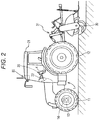
- this exemplary tractor may be provided with a cab 20 in a central portion of the vehicle body 1 supported by front wheels 11 and rear wheels 12.
- the tractor may be equipped with the work device 30, which in this example is a rotary tilling machine, via a hydraulic lifting mechanism 31 at a rear of the vehicle body 1.
- the front wheels 11 may function as steering control wheels through which the tractor changes a travel direction when a steering angle of the steering control wheels is changed.
- the steering angle of the front wheels 11 may be changed by an operation of a steering mechanism 13.
- the steering mechanism 13 may include a steering motor 14 for automatic steering.
- the front wheels 11 can be steered by operating a steering wheel 22 disposed in the cab 20.
- the cab 20 may be equipped with a general purpose terminal 4 that may provide a user with information and receive instructions from the user.
- the general purpose terminal 4 may be implemented by one or more processors and one or more storage devices, such as a memory, coupled to the one or more processors.
- a satellite positioning module 80 may be provided in a cabin 21 of the tractor.
- a satellite antenna for receiving a global navigation satellite system (GNSS) signal (including a GPS signal) may be attached at a ceiling area of the cabin 21.
- GNSS global navigation satellite system
- the satellite positioning module 80 may be combined with an inertial navigation module incorporated with a gyro acceleration sensor and/or a magnetic director sensor for complementing satellite navigation.
- the inertial navigation module may be provided in a different location from the location of the satellite positioning module 80.
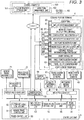
- Fig. 3 illustrates an exemplary control system configured in this tractor.
- the control system of this exemplary embodiment may include a first control unit, which may be the general purpose terminal 4 including a graphical user interface, a controlling unit 5 that may control the vehicle body 1 and the work device 30 of the tractor, and/or a remote controller 84 for wirelessly controlling travel start and travel stop of the tractor from outside.
- the travel route generation device according to the present invention may be modularized as a route generation module 6, and be incorporated into the general purpose terminal 4.
- the general purpose terminal 4 may have functions of a general computer system, such as a communication control unit 40, a touch panel 60, and an input/output management unit 61 that manages an input operation on the touch panel 60 and/or information display on the touch panel 60.
- the general purpose terminal 4 may be coupled to the controlling unit 5 in such a manner that the general purpose terminal 4 can exchange data by vehicle-mounted LAN, wireless communication, cable communication, or the like.
- the general purpose terminal 4 can exchange data with a control computer 100 configured in a remote control center KS via a wireless channel or the Internet.
- field information including a position of the field on a map and arrangement of farm roads surrounding the field may be stored in a field information storage unit 101 of the control computer 100, and this field information may be needed for finding out the field to work.
- the control computer 100 may also include a work plan management unit 102 that manages a work plan describing the work in a specified field.
- the general purpose terminal 4 can access the control computer 100, and download the field information from the field information storage unit 101 and the work plan from the work plan management unit 102.
- the general purpose terminal 4 can also input the field information and the work plan via a recording medium such as a USB memory.
- the route generation module 6 may include a work field shape calculation submodule 62 that calculates a shape of the target work region, which is a valid work region of the field, through the teaching travel, and/or a travel route generation unit 63 that generates a travel route for the tractor to travel in the target work region.
- the work field shape calculation submodule 62 may include a starting point registration unit 621, an intermediate point registration unit 622, an end point registration unit 623, a basic shape calculation unit 624, an entrance passage information generation unit 625, and/or a shape editing unit 626. Furthermore, an inner point registration unit 627 may also be prepared as an option.
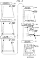
- a basic role of each functional unit of the route generation module 6 will be described with reference to a flowchart of an exemplary field shape calculation process and a travel route generation process illustrated in Fig. 4 .
- the field shape is a trapezoid, and an entrance passage inclined downward is provided at a right end of an upper side.
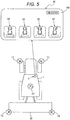
- aiming points T1, T2, T3, and T4 may be prescribed at four corners of the tractor. Distances between these aiming points T1, T2, T3, and T4 and the own position based on positioning data from the satellite positioning module 80 (illustrated with a black dot at the center of the vehicle body in Fig. 5 ) may be set in advance.
- Position coordinates of the aiming points T1, T2, T3, and T4 can be calculated from the own position.
- the touch panel 60 may display aiming point selection buttons B1, B2, B3, and B4, and the aiming point corresponding to the pushed aiming point selection button B1, B2, B3, or B4 may become valid in the following field shape calculation process.
- the tractor that passes through a farm road and reaches the target field may perform teaching travel in order to calculate the shape of the field.
- the aiming point selection button B1 is pushed, and the aiming point T1 is valid.
- a driver may operate the tractor such that the tractor passes through the entrance passage and that the aiming point T1 comes to a right end (e.g. first endpoint) after going down the entrance passage.
- the driver then may push a registration button RB displayed on the touch panel 60 (see Fig. 5 ).
- the starting point registration unit 621 may register the first endpoint as a starting point (illustrated with a black dot and Ps in Fig. 4 ).
- the driver may advance the tractor such that the aiming point T1 comes to a left end of the upper side, which may be a shape feature point of the field (e.g. geometrical shape body, here, a vertex of the trapezoid), and may then push the registration button RB.
- the intermediate point registration unit 622 may register the left end of the upper side as a first intermediate point (illustrated with a black dot and P1 in Fig. 4 ).
- the driver may advance the tractor such that the aiming point T1 comes to a left end of a lower side, and may then push the registration button RB.
- the intermediate point registration unit 622 may register the left end of the lower side as a second intermediate point (illustrated with a black dot and P2 in Fig. 4 ). Furthermore, the driver may advance the tractor such that the aiming point T1 comes to a right end of the lower side, and may then push the registration button RB. Accordingly, the intermediate point registration unit 622 may register the right end of the lower side as a third intermediate point (illustrated with a black dot and P3 in Fig. 4 ).
- the driver may advance the tractor along the ridge (e.g. boundary) from the right end of the lower side of the field at which the third intermediate point may be set, stop the tractor at a position at which the aiming point T1 comes to an endpoint that is an intersection of the entrance passage and the boundary, and may then push the registration button RB. Since the position at which the registration button RB is pushed is close to the starting point, the end point registration unit 623 may regard this position as an end point (illustrated with a black dot and Pe in Fig. 4 ) and register the position. Alternatively, the driver may instruct the end point registration unit 623 that the registered position is the end point, by performing an instruction operation of indicating the end point and then pushing the registration button RB.
- the end point registration unit 623 may regard this position as an end point (illustrated with a black dot and Pe in Fig. 4 ) and register the position.
- the driver may instruct the end point registration unit 623 that the registered position is the end point, by performing an instruction operation of indicating the
- the basic shape calculation unit 624 may connect these points to calculate the basic shape of the work field.
- the entrance passage information generation unit 625 may generate entrance passage information, such as a shape and size of the entrance passage and a travel direction in the entrance passage.
- the entrance passage since the entrance passage may be a partial passage, the entrance passage may be substantially regarded as a quadrangle. Two opposite vertices of this quadrangle indicating the entrance passage may be the starting point and the end point (illustrated with black dots and Ps and Pe in Fig. 4 ). Therefore, the shape and size of the entrance passage may be obtained by calculating two more vertices. Therefore, when this quadrangle indicating the entrance passage is regarded as a parallelogram (e.g. including a rectangle and a square) with extension lines of the boundary lines of the adjacent field (e.g.
- a parallelogram e.g. including a rectangle and a square
- a vertex inside the field referred to as an outer point
- a vertex outside the field referred to as an inner point
- the inner point is illustrated with a white circle and Pa
- the outer point is illustrated with a white circle and Pb.
- a direction from a side that connects the outer point and the end point to a side that connects the starting point and the inner point can be regarded as an entry direction (e.g. travel direction) of the tractor into the field.
- a region other than the entrance passage in the field in other words, for example, the target work region which is the valid work region may be prescribed by a contour line obtained by connecting the starting point, the three intermediate points, the end point, and the inner point.
- This contour line which may be substantially obtained by traveling of the tractor, is not necessarily accurate. For example, when there are recessed or protruding sections over which the tractor cannot travel, such recessed or protruding sections may be neglected. Therefore, the shape editing unit 626 may be provided that modifies the contour line obtained by connecting the starting point, the three intermediate points, the end point, and the inner point. This shape editing unit 626 may enable the user to edit the contour line displayed on the touch panel 60, for example, in a manner of editing a Bézier curve.
- the driver may further operate the tractor such that the aiming point T1 comes to a right end (e.g. first endpoint) downward along the entrance passage to an endpoint inside the boundary line of the entrance passage and the target work region, stop the tractor at a position to which the aiming point T1 comes, and then push the registration button RB.
- the inner point registration unit 627 may register the position as the inner point (illustrated with a white circle and Pa in Fig. 4 ).
- the other aiming points T2, T3, and/or T4 may be able to easily approach a target position in some cases.
- the aiming points T3 and/or T4 may be convenient. In such a case, selecting and pushing a button corresponding to the desired aiming point from the aiming point selection buttons B1, B2, B3, and B4 may cause the valid aiming point to be changed.
- the travel route generation unit 63 may generate the travel route for the work vehicle to automatically travel in the target work region.
- the travel route to be generated includes an inside travel route including straight movement routes and U-turn routes that connect the straight movement routes, and a circumferential travel route for performing circumferential travel in an outer region of the field.
- an algorithm may be employed that generates a spiral travel route along which the tractor travels spirally in the field, and other travel routes.
- the controlling unit 5 which may be a core element of the control system of the tractor, may include an output processing unit 7 and/or an input processing unit 8, which respectively may function as input and output interfaces, and/or a communication processing unit 70.
- the output processing unit 7 may be coupled to devices equipped in the tractor, such as vehicle travel instruments 71, work device instruments 72, and/or a notification device 73.
- vehicle travel instruments 71 may include, but are not limited to, the steering motor 14, and although not illustrated, devices to be controlled for allowing the vehicle to travel, such as a transmission mechanism and an engine unit.
- the work device instruments 72 may include, but are not limited to, devices such as a drive mechanism for the work device 30 and the lifting mechanism 31 that raises and lowers the work device 30.
- the notification device 73 may include, but is not limited to, a display, lamps, and/or a speaker.
- the notification device 73 may be used for notifying the driver and/or supervisor of attention information and/or warning information, such as travel precautions and/or deviation from the target travel route when the work vehicle is automatically steered.
- the communication processing unit 70 may have a function of transmitting data processed by the controlling unit 5 to the control computer 100, and receiving various kinds of data from the control computer 100. Furthermore, the communication processing unit 70 may input remote control instructions from the remote controller 84.
- the input processing unit 8 may be coupled to, for example, the satellite positioning module 80, travel system detection sensors 81, work system detection sensors 82, and/or an automatic/manual switch 83.
- the travel system detection sensors 81 may include, but are not limited to, sensors for detecting travel states such as an engine speed and a transmission state.
- the work system detection sensors 82 may include sensors for detecting a position and/or inclination of the work device 30, sensors for detecting workloads, and the like.
- the automatic/manual switch 83 may be a switch for selecting either an automatic travel mode for traveling with automatic steering or a manual steering mode for traveling with manual steering.
- the controlling unit 5 may include a travel control unit 50, a work control unit 54, an own position calculation unit 53, a travel route setting unit 55, and/or a notification unit 56.
- the own position calculation unit 53 may calculate the own position.
- the calculated own position may be provided to the work field shape calculation submodule.
- the travel control unit 50 for controlling the vehicle travel instruments 71 may include a manual travel control unit 51 and an automatic travel control unit 52.
- the manual travel control unit 51 may control the vehicle travel instruments 71.
- the automatic travel control unit 52 may calculate discrepancies in direction and position between the travel route that is set by the travel route setting unit 55 and the own position, and generate an automatic steering instruction. This automatic steering instruction may be output to the steering motor 14 via the output processing unit 7.
- the automatic travel control unit 52 may stop the tractor on the basis of a stop instruction from the remote controller 84, and cause the tractor to start travel on the basis of a starting instruction from the remote controller 84.
- the work control unit 54 may provide control signals to the work device instruments 72.
- the notification unit 56 may generates notification signals (e.g. display data and/or voice data) for notifying information necessary for the driver and/or the supervisor, and provide the notification signals to the notification device 73 incorporated into an instruments panel.
- the travel route setting unit 55 may receive the travel route generated by the route generation module 6 via the communication processing unit 70 from the travel route generation unit 63 of the general purpose terminal 4. The travel route setting unit 55 may then set the travel route as a target travel route for the tractor.
- the travel route generation device is applicable to the work vehicle that works along the set travel route in the work field.
Landscapes
- Engineering & Computer Science (AREA)
- Life Sciences & Earth Sciences (AREA)
- Radar, Positioning & Navigation (AREA)
- Remote Sensing (AREA)
- Physics & Mathematics (AREA)
- General Physics & Mathematics (AREA)
- Aviation & Aerospace Engineering (AREA)
- Automation & Control Theory (AREA)
- Environmental Sciences (AREA)
- Soil Sciences (AREA)
- Mechanical Engineering (AREA)
- Electromagnetism (AREA)
- Control Of Position, Course, Altitude, Or Attitude Of Moving Bodies (AREA)
- Guiding Agricultural Machines (AREA)
Applications Claiming Priority (1)
| Application Number | Priority Date | Filing Date | Title |
|---|---|---|---|
| JP2017008344A JP6971577B2 (ja) | 2017-01-20 | 2017-01-20 | 走行経路生成装置及び走行経路生成プログラム |
Publications (2)
| Publication Number | Publication Date |
|---|---|
| EP3351077A1 true EP3351077A1 (fr) | 2018-07-25 |
| EP3351077B1 EP3351077B1 (fr) | 2020-04-01 |
Family
ID=59152620
Family Applications (1)
| Application Number | Title | Priority Date | Filing Date |
|---|---|---|---|
| EP17001059.9A Active EP3351077B1 (fr) | 2017-01-20 | 2017-06-21 | Dispositif de génération d'itinéraire et programme de génération d'itinéraire |
Country Status (4)
| Country | Link |
|---|---|
| EP (1) | EP3351077B1 (fr) |
| JP (2) | JP6971577B2 (fr) |
| KR (1) | KR102398388B1 (fr) |
| CN (1) | CN108334065B (fr) |
Cited By (3)
| Publication number | Priority date | Publication date | Assignee | Title |
|---|---|---|---|---|
| EP3900510A4 (fr) * | 2018-12-20 | 2022-09-21 | Kubota Corporation | Machine d'opération en déplacement |
| US11968917B2 (en) | 2018-12-26 | 2024-04-30 | Kubota Corporation | Working vehicle and working machine having the working vehicle |
| US12022759B2 (en) | 2018-12-26 | 2024-07-02 | Kubota Corporation | Working vehicle |
Families Citing this family (20)
| Publication number | Priority date | Publication date | Assignee | Title |
|---|---|---|---|---|
| JP7130535B2 (ja) * | 2018-08-01 | 2022-09-05 | 株式会社クボタ | 自動走行制御システム |
| WO2020026650A1 (fr) * | 2018-08-01 | 2020-02-06 | 株式会社クボタ | Système de commande de déplacement automatique, procédé de commande de déplacement automatique, programme de commande de déplacement automatique et support de stockage |
| US11796327B2 (en) * | 2018-09-06 | 2023-10-24 | Honda Motor Co., Ltd. | Route subdivision apparatus |
| CN112912808B (zh) * | 2018-10-22 | 2023-12-26 | 株式会社尼罗沃克 | 行驶路径生成系统、行驶路径生成方法、计算机可读取记录介质、坐标测量系统以及无人机 |
| JP7173858B2 (ja) * | 2018-12-21 | 2022-11-16 | 株式会社クボタ | 植播系作業機、及び、植播系作業機の自動走行制御システム |
| JP7175743B2 (ja) * | 2018-12-21 | 2022-11-21 | 株式会社クボタ | 植播系作業機の自動走行制御システム |
| KR102845158B1 (ko) * | 2018-12-21 | 2025-08-12 | 가부시끼 가이샤 구보다 | 파식계 작업기 및 파식계 작업기의 자동 주행 제어 시스템, 포장 작업차 및 주행 경로 생성 시스템 |
| JP7069002B2 (ja) * | 2018-12-21 | 2022-05-17 | 株式会社クボタ | 圃場作業車及び圃場地図データ生成システム |
| JP7096531B2 (ja) * | 2018-12-27 | 2022-07-06 | 井関農機株式会社 | 作業車両の自律走行システム |
| CN110366913A (zh) * | 2019-04-04 | 2019-10-25 | 丰疆智能科技股份有限公司 | 插秧机及其插秧方法和插秧系统 |
| JP7242446B2 (ja) * | 2019-06-28 | 2023-03-20 | 株式会社クボタ | 作業支援システム、作業車両 |
| CN110502010B (zh) * | 2019-08-15 | 2021-06-04 | 同济大学 | 一种基于贝塞尔曲线的移动机器人室内自主导航控制方法 |
| US12154051B2 (en) * | 2019-11-18 | 2024-11-26 | Hd Hyundai Infracore Co., Ltd. | Method of making work plans for construction machinery |
| JP7413031B2 (ja) * | 2020-01-14 | 2024-01-15 | 株式会社クボタ | 作業機 |
| JP7386394B2 (ja) * | 2020-05-22 | 2023-11-27 | 井関農機株式会社 | 作業車両の監視制御システム |
| CN111766870B (zh) * | 2020-05-29 | 2021-11-05 | 广州极飞科技股份有限公司 | 过渡路径和作业路径的规划方法及相关装置 |
| JP7485586B2 (ja) * | 2020-11-12 | 2024-05-16 | ヤンマーホールディングス株式会社 | 作業領域設定システム、作業領域設定方法、及び作業領域設定プログラム |
| CN112783159A (zh) * | 2020-12-28 | 2021-05-11 | 上海联适导航技术股份有限公司 | 一种作业控制方法、装置、设备及可读存储介质 |
| JP7466201B2 (ja) * | 2021-02-19 | 2024-04-12 | 国立研究開発法人農業・食品産業技術総合研究機構 | 圃場作業車両の走行経路設定装置、走行経路設定方法および走行経路設定用プログラム |
| JP7416437B2 (ja) * | 2021-03-26 | 2024-01-17 | 国立研究開発法人農業・食品産業技術総合研究機構 | 圃場作業車両の走行経路設定装置、走行経路設定方法および走行経路設定用プログラム |
Citations (6)
| Publication number | Priority date | Publication date | Assignee | Title |
|---|---|---|---|---|
| US20040193349A1 (en) * | 2003-03-31 | 2004-09-30 | Flann Nicholas Simon | Method and system for determining an efficient vehicle path |
| US20070192024A1 (en) * | 2003-03-31 | 2007-08-16 | Deere & Company | Path planner and method for planning a contour path of a vehicle |
| WO2012142395A1 (fr) * | 2011-04-15 | 2012-10-18 | Bayer Cropscience Lp | Système d'information visuelle et application de mobilité informatique pour personnels de terrain |
| JP2016031649A (ja) | 2014-07-29 | 2016-03-07 | 株式会社クボタ | 作業車協調システム |
| EP3042554A1 (fr) * | 2014-12-10 | 2016-07-13 | Iseki & Co., Ltd. | Véhicule de travail agricole |
| WO2017004074A1 (fr) * | 2015-06-30 | 2017-01-05 | Precision Planting Llc | Systèmes et procédés pour la capture d'images et l'analyse de champs agricoles |
Family Cites Families (11)
| Publication number | Priority date | Publication date | Assignee | Title |
|---|---|---|---|---|
| JPH07281742A (ja) * | 1994-04-04 | 1995-10-27 | Kubota Corp | ビーム光誘導式作業車用の走行制御装置 |
| JP3656332B2 (ja) * | 1996-08-28 | 2005-06-08 | 独立行政法人農業・生物系特定産業技術研究機構 | 作業車両の無人走行による無人作業方法 |
| JP3814230B2 (ja) * | 2002-06-05 | 2006-08-23 | ヤンマー農機株式会社 | 農業用散布作業車 |
| JP4999965B2 (ja) | 2010-06-04 | 2012-08-15 | 中国電力株式会社 | 自動耕作方法、及び自動耕作システム |
| CN102167038B (zh) * | 2010-12-03 | 2013-09-04 | 北京农业信息技术研究中心 | 农田地块全区域覆盖最优作业路径生成方法及装置 |
| JP5785415B2 (ja) * | 2011-03-29 | 2015-09-30 | 株式会社デンソーアイティーラボラトリ | 経路案内生成装置、方法及びシステム |
| JP5807518B2 (ja) * | 2011-11-09 | 2015-11-10 | 富士通株式会社 | 推定装置、推定方法、および推定プログラム |
| CN102607582A (zh) * | 2012-03-07 | 2012-07-25 | 深圳市赛格导航科技股份有限公司 | 用城市出入口点作为路标指引路径规划的方法及系统 |
| KR20210082559A (ko) * | 2014-02-06 | 2021-07-05 | 얀마 파워 테크놀로지 가부시키가이샤 | 병주 작업 시스템 |
| JP2016156690A (ja) * | 2015-02-24 | 2016-09-01 | 井関農機株式会社 | 作業車両 |
| JP6569319B2 (ja) * | 2015-06-17 | 2019-09-04 | 日本製鉄株式会社 | 耐摩耗鋼板およびその製造方法 |
-
2017
- 2017-01-20 JP JP2017008344A patent/JP6971577B2/ja active Active
- 2017-05-31 CN CN201710398228.4A patent/CN108334065B/zh active Active
- 2017-05-31 KR KR1020170067886A patent/KR102398388B1/ko active Active
- 2017-06-21 EP EP17001059.9A patent/EP3351077B1/fr active Active
-
2021
- 2021-08-17 JP JP2021132710A patent/JP7209783B2/ja active Active
Patent Citations (7)
| Publication number | Priority date | Publication date | Assignee | Title |
|---|---|---|---|---|
| US20040193349A1 (en) * | 2003-03-31 | 2004-09-30 | Flann Nicholas Simon | Method and system for determining an efficient vehicle path |
| US20070192024A1 (en) * | 2003-03-31 | 2007-08-16 | Deere & Company | Path planner and method for planning a contour path of a vehicle |
| WO2012142395A1 (fr) * | 2011-04-15 | 2012-10-18 | Bayer Cropscience Lp | Système d'information visuelle et application de mobilité informatique pour personnels de terrain |
| JP2016031649A (ja) | 2014-07-29 | 2016-03-07 | 株式会社クボタ | 作業車協調システム |
| US20160174453A1 (en) * | 2014-07-29 | 2016-06-23 | Kubota Corporation | Work Vehicle Coordinating System |
| EP3042554A1 (fr) * | 2014-12-10 | 2016-07-13 | Iseki & Co., Ltd. | Véhicule de travail agricole |
| WO2017004074A1 (fr) * | 2015-06-30 | 2017-01-05 | Precision Planting Llc | Systèmes et procédés pour la capture d'images et l'analyse de champs agricoles |
Cited By (3)
| Publication number | Priority date | Publication date | Assignee | Title |
|---|---|---|---|---|
| EP3900510A4 (fr) * | 2018-12-20 | 2022-09-21 | Kubota Corporation | Machine d'opération en déplacement |
| US11968917B2 (en) | 2018-12-26 | 2024-04-30 | Kubota Corporation | Working vehicle and working machine having the working vehicle |
| US12022759B2 (en) | 2018-12-26 | 2024-07-02 | Kubota Corporation | Working vehicle |
Also Published As
| Publication number | Publication date |
|---|---|
| CN108334065B (zh) | 2022-09-16 |
| KR20180086108A (ko) | 2018-07-30 |
| EP3351077B1 (fr) | 2020-04-01 |
| JP2018116608A (ja) | 2018-07-26 |
| JP2021184300A (ja) | 2021-12-02 |
| CN108334065A (zh) | 2018-07-27 |
| JP6971577B2 (ja) | 2021-11-24 |
| JP7209783B2 (ja) | 2023-01-20 |
| KR102398388B1 (ko) | 2022-05-16 |
Similar Documents
| Publication | Publication Date | Title |
|---|---|---|
| EP3351077B1 (fr) | Dispositif de génération d'itinéraire et programme de génération d'itinéraire | |
| US10989541B2 (en) | Travel route generation device and travel route generation method | |
| EP3336794B1 (fr) | Appareil et procédé de génération d'une voie de voyage pour un véhicule agricole | |
| EP3351078B1 (fr) | Dispositif de génération d'un itinéraire | |
| EP3267151B1 (fr) | Programme de recherche d'itinéraire, système de recherche d'itinéraire et véhicule de travail incorporé ayant un système de recherche d'itinéraire | |
| US9880558B2 (en) | Travel control device | |
| JP7543591B2 (ja) | トラクタ | |
| CN108334064A (zh) | 自动行驶作业车 | |
| JP7069002B2 (ja) | 圃場作業車及び圃場地図データ生成システム | |
| WO2017216983A1 (fr) | Système de génération de trajet de déplacement de champ et véhicule de travail de champ | |
| WO2017154772A1 (fr) | Dispositif de génération de trajet | |
| JP2019170197A (ja) | 領域登録システム | |
| JP6879896B2 (ja) | 作業車のための衛星測位システム | |
| JP2020099225A (ja) | 走行作業機 | |
| JP2020171318A (ja) | 自動走行作業車 | |
| JP7034860B2 (ja) | 領域登録システム | |
| JP2021083343A (ja) | 領域登録システム | |
| US12342742B2 (en) | Automatic travel system and automatic travel method | |
| JP2020099227A (ja) | 走行作業機 | |
| EP4165973A1 (fr) | Système de gestion de travail pour véhicule de travail | |
| JP2005186746A (ja) | 駐車支援システム | |
| JP2023139432A (ja) | 作業車両 |
Legal Events
| Date | Code | Title | Description |
|---|---|---|---|
| PUAI | Public reference made under article 153(3) epc to a published international application that has entered the european phase |
Free format text: ORIGINAL CODE: 0009012 |
|
| STAA | Information on the status of an ep patent application or granted ep patent |
Free format text: STATUS: THE APPLICATION HAS BEEN PUBLISHED |
|
| AK | Designated contracting states |
Kind code of ref document: A1 Designated state(s): AL AT BE BG CH CY CZ DE DK EE ES FI FR GB GR HR HU IE IS IT LI LT LU LV MC MK MT NL NO PL PT RO RS SE SI SK SM TR |
|
| AX | Request for extension of the european patent |
Extension state: BA ME |
|
| STAA | Information on the status of an ep patent application or granted ep patent |
Free format text: STATUS: REQUEST FOR EXAMINATION WAS MADE |
|
| 17P | Request for examination filed |
Effective date: 20190124 |
|
| RBV | Designated contracting states (corrected) |
Designated state(s): AL AT BE BG CH CY CZ DE DK EE ES FI FR GB GR HR HU IE IS IT LI LT LU LV MC MK MT NL NO PL PT RO RS SE SI SK SM TR |
|
| GRAP | Despatch of communication of intention to grant a patent |
Free format text: ORIGINAL CODE: EPIDOSNIGR1 |
|
| STAA | Information on the status of an ep patent application or granted ep patent |
Free format text: STATUS: GRANT OF PATENT IS INTENDED |
|
| INTG | Intention to grant announced |
Effective date: 20191108 |
|
| GRAS | Grant fee paid |
Free format text: ORIGINAL CODE: EPIDOSNIGR3 |
|
| GRAA | (expected) grant |
Free format text: ORIGINAL CODE: 0009210 |
|
| STAA | Information on the status of an ep patent application or granted ep patent |
Free format text: STATUS: THE PATENT HAS BEEN GRANTED |
|
| AK | Designated contracting states |
Kind code of ref document: B1 Designated state(s): AL AT BE BG CH CY CZ DE DK EE ES FI FR GB GR HR HU IE IS IT LI LT LU LV MC MK MT NL NO PL PT RO RS SE SI SK SM TR |
|
| REG | Reference to a national code |
Ref country code: GB Ref legal event code: FG4D |
|
| REG | Reference to a national code |
Ref country code: CH Ref legal event code: EP Ref country code: AT Ref legal event code: REF Ref document number: 1250145 Country of ref document: AT Kind code of ref document: T Effective date: 20200415 |
|
| REG | Reference to a national code |
Ref country code: DE Ref legal event code: R096 Ref document number: 602017013780 Country of ref document: DE |
|
| REG | Reference to a national code |
Ref country code: IE Ref legal event code: FG4D |
|
| PG25 | Lapsed in a contracting state [announced via postgrant information from national office to epo] |
Ref country code: BG Free format text: LAPSE BECAUSE OF FAILURE TO SUBMIT A TRANSLATION OF THE DESCRIPTION OR TO PAY THE FEE WITHIN THE PRESCRIBED TIME-LIMIT Effective date: 20200701 |
|
| REG | Reference to a national code |
Ref country code: NL Ref legal event code: MP Effective date: 20200401 |
|
| REG | Reference to a national code |
Ref country code: LT Ref legal event code: MG4D |
|
| PG25 | Lapsed in a contracting state [announced via postgrant information from national office to epo] |
Ref country code: LT Free format text: LAPSE BECAUSE OF FAILURE TO SUBMIT A TRANSLATION OF THE DESCRIPTION OR TO PAY THE FEE WITHIN THE PRESCRIBED TIME-LIMIT Effective date: 20200401 Ref country code: SE Free format text: LAPSE BECAUSE OF FAILURE TO SUBMIT A TRANSLATION OF THE DESCRIPTION OR TO PAY THE FEE WITHIN THE PRESCRIBED TIME-LIMIT Effective date: 20200401 Ref country code: NL Free format text: LAPSE BECAUSE OF FAILURE TO SUBMIT A TRANSLATION OF THE DESCRIPTION OR TO PAY THE FEE WITHIN THE PRESCRIBED TIME-LIMIT Effective date: 20200401 Ref country code: PT Free format text: LAPSE BECAUSE OF FAILURE TO SUBMIT A TRANSLATION OF THE DESCRIPTION OR TO PAY THE FEE WITHIN THE PRESCRIBED TIME-LIMIT Effective date: 20200817 Ref country code: FI Free format text: LAPSE BECAUSE OF FAILURE TO SUBMIT A TRANSLATION OF THE DESCRIPTION OR TO PAY THE FEE WITHIN THE PRESCRIBED TIME-LIMIT Effective date: 20200401 Ref country code: IS Free format text: LAPSE BECAUSE OF FAILURE TO SUBMIT A TRANSLATION OF THE DESCRIPTION OR TO PAY THE FEE WITHIN THE PRESCRIBED TIME-LIMIT Effective date: 20200801 Ref country code: CZ Free format text: LAPSE BECAUSE OF FAILURE TO SUBMIT A TRANSLATION OF THE DESCRIPTION OR TO PAY THE FEE WITHIN THE PRESCRIBED TIME-LIMIT Effective date: 20200401 Ref country code: GR Free format text: LAPSE BECAUSE OF FAILURE TO SUBMIT A TRANSLATION OF THE DESCRIPTION OR TO PAY THE FEE WITHIN THE PRESCRIBED TIME-LIMIT Effective date: 20200702 Ref country code: NO Free format text: LAPSE BECAUSE OF FAILURE TO SUBMIT A TRANSLATION OF THE DESCRIPTION OR TO PAY THE FEE WITHIN THE PRESCRIBED TIME-LIMIT Effective date: 20200701 |
|
| REG | Reference to a national code |
Ref country code: AT Ref legal event code: MK05 Ref document number: 1250145 Country of ref document: AT Kind code of ref document: T Effective date: 20200401 |
|
| PG25 | Lapsed in a contracting state [announced via postgrant information from national office to epo] |
Ref country code: LV Free format text: LAPSE BECAUSE OF FAILURE TO SUBMIT A TRANSLATION OF THE DESCRIPTION OR TO PAY THE FEE WITHIN THE PRESCRIBED TIME-LIMIT Effective date: 20200401 Ref country code: RS Free format text: LAPSE BECAUSE OF FAILURE TO SUBMIT A TRANSLATION OF THE DESCRIPTION OR TO PAY THE FEE WITHIN THE PRESCRIBED TIME-LIMIT Effective date: 20200401 Ref country code: HR Free format text: LAPSE BECAUSE OF FAILURE TO SUBMIT A TRANSLATION OF THE DESCRIPTION OR TO PAY THE FEE WITHIN THE PRESCRIBED TIME-LIMIT Effective date: 20200401 |
|
| PG25 | Lapsed in a contracting state [announced via postgrant information from national office to epo] |
Ref country code: AL Free format text: LAPSE BECAUSE OF FAILURE TO SUBMIT A TRANSLATION OF THE DESCRIPTION OR TO PAY THE FEE WITHIN THE PRESCRIBED TIME-LIMIT Effective date: 20200401 |
|
| REG | Reference to a national code |
Ref country code: DE Ref legal event code: R097 Ref document number: 602017013780 Country of ref document: DE |
|
| PG25 | Lapsed in a contracting state [announced via postgrant information from national office to epo] |
Ref country code: RO Free format text: LAPSE BECAUSE OF FAILURE TO SUBMIT A TRANSLATION OF THE DESCRIPTION OR TO PAY THE FEE WITHIN THE PRESCRIBED TIME-LIMIT Effective date: 20200401 Ref country code: ES Free format text: LAPSE BECAUSE OF FAILURE TO SUBMIT A TRANSLATION OF THE DESCRIPTION OR TO PAY THE FEE WITHIN THE PRESCRIBED TIME-LIMIT Effective date: 20200401 Ref country code: IT Free format text: LAPSE BECAUSE OF FAILURE TO SUBMIT A TRANSLATION OF THE DESCRIPTION OR TO PAY THE FEE WITHIN THE PRESCRIBED TIME-LIMIT Effective date: 20200401 Ref country code: SM Free format text: LAPSE BECAUSE OF FAILURE TO SUBMIT A TRANSLATION OF THE DESCRIPTION OR TO PAY THE FEE WITHIN THE PRESCRIBED TIME-LIMIT Effective date: 20200401 Ref country code: AT Free format text: LAPSE BECAUSE OF FAILURE TO SUBMIT A TRANSLATION OF THE DESCRIPTION OR TO PAY THE FEE WITHIN THE PRESCRIBED TIME-LIMIT Effective date: 20200401 Ref country code: EE Free format text: LAPSE BECAUSE OF FAILURE TO SUBMIT A TRANSLATION OF THE DESCRIPTION OR TO PAY THE FEE WITHIN THE PRESCRIBED TIME-LIMIT Effective date: 20200401 Ref country code: DK Free format text: LAPSE BECAUSE OF FAILURE TO SUBMIT A TRANSLATION OF THE DESCRIPTION OR TO PAY THE FEE WITHIN THE PRESCRIBED TIME-LIMIT Effective date: 20200401 Ref country code: MC Free format text: LAPSE BECAUSE OF FAILURE TO SUBMIT A TRANSLATION OF THE DESCRIPTION OR TO PAY THE FEE WITHIN THE PRESCRIBED TIME-LIMIT Effective date: 20200401 |
|
| REG | Reference to a national code |
Ref country code: CH Ref legal event code: PL |
|
| PLBE | No opposition filed within time limit |
Free format text: ORIGINAL CODE: 0009261 |
|
| STAA | Information on the status of an ep patent application or granted ep patent |
Free format text: STATUS: NO OPPOSITION FILED WITHIN TIME LIMIT |
|
| PG25 | Lapsed in a contracting state [announced via postgrant information from national office to epo] |
Ref country code: SK Free format text: LAPSE BECAUSE OF FAILURE TO SUBMIT A TRANSLATION OF THE DESCRIPTION OR TO PAY THE FEE WITHIN THE PRESCRIBED TIME-LIMIT Effective date: 20200401 Ref country code: PL Free format text: LAPSE BECAUSE OF FAILURE TO SUBMIT A TRANSLATION OF THE DESCRIPTION OR TO PAY THE FEE WITHIN THE PRESCRIBED TIME-LIMIT Effective date: 20200401 |
|
| 26N | No opposition filed |
Effective date: 20210112 |
|
| PG25 | Lapsed in a contracting state [announced via postgrant information from national office to epo] |
Ref country code: LU Free format text: LAPSE BECAUSE OF NON-PAYMENT OF DUE FEES Effective date: 20200621 |
|
| REG | Reference to a national code |
Ref country code: BE Ref legal event code: MM Effective date: 20200630 |
|
| PG25 | Lapsed in a contracting state [announced via postgrant information from national office to epo] |
Ref country code: CH Free format text: LAPSE BECAUSE OF NON-PAYMENT OF DUE FEES Effective date: 20200630 Ref country code: LI Free format text: LAPSE BECAUSE OF NON-PAYMENT OF DUE FEES Effective date: 20200630 Ref country code: IE Free format text: LAPSE BECAUSE OF NON-PAYMENT OF DUE FEES Effective date: 20200621 |
|
| PG25 | Lapsed in a contracting state [announced via postgrant information from national office to epo] |
Ref country code: BE Free format text: LAPSE BECAUSE OF NON-PAYMENT OF DUE FEES Effective date: 20200630 Ref country code: SI Free format text: LAPSE BECAUSE OF FAILURE TO SUBMIT A TRANSLATION OF THE DESCRIPTION OR TO PAY THE FEE WITHIN THE PRESCRIBED TIME-LIMIT Effective date: 20200401 |
|
| GBPC | Gb: european patent ceased through non-payment of renewal fee |
Effective date: 20210621 |
|
| PG25 | Lapsed in a contracting state [announced via postgrant information from national office to epo] |
Ref country code: GB Free format text: LAPSE BECAUSE OF NON-PAYMENT OF DUE FEES Effective date: 20210621 |
|
| PG25 | Lapsed in a contracting state [announced via postgrant information from national office to epo] |
Ref country code: TR Free format text: LAPSE BECAUSE OF FAILURE TO SUBMIT A TRANSLATION OF THE DESCRIPTION OR TO PAY THE FEE WITHIN THE PRESCRIBED TIME-LIMIT Effective date: 20200401 Ref country code: MT Free format text: LAPSE BECAUSE OF FAILURE TO SUBMIT A TRANSLATION OF THE DESCRIPTION OR TO PAY THE FEE WITHIN THE PRESCRIBED TIME-LIMIT Effective date: 20200401 Ref country code: CY Free format text: LAPSE BECAUSE OF FAILURE TO SUBMIT A TRANSLATION OF THE DESCRIPTION OR TO PAY THE FEE WITHIN THE PRESCRIBED TIME-LIMIT Effective date: 20200401 |
|
| PG25 | Lapsed in a contracting state [announced via postgrant information from national office to epo] |
Ref country code: MK Free format text: LAPSE BECAUSE OF FAILURE TO SUBMIT A TRANSLATION OF THE DESCRIPTION OR TO PAY THE FEE WITHIN THE PRESCRIBED TIME-LIMIT Effective date: 20200401 |
|
| PGFP | Annual fee paid to national office [announced via postgrant information from national office to epo] |
Ref country code: DE Payment date: 20250429 Year of fee payment: 9 |
|
| PGFP | Annual fee paid to national office [announced via postgrant information from national office to epo] |
Ref country code: FR Payment date: 20250508 Year of fee payment: 9 |