EP3351228A1 - Ensemble de roue modulaire destiné à un fauteuil roulant - Google Patents
Ensemble de roue modulaire destiné à un fauteuil roulant Download PDFInfo
- Publication number
- EP3351228A1 EP3351228A1 EP17205230.0A EP17205230A EP3351228A1 EP 3351228 A1 EP3351228 A1 EP 3351228A1 EP 17205230 A EP17205230 A EP 17205230A EP 3351228 A1 EP3351228 A1 EP 3351228A1
- Authority
- EP
- European Patent Office
- Prior art keywords
- modular
- wheelchair
- wheel
- wheel assembly
- chair base
- Prior art date
- Legal status (The legal status is an assumption and is not a legal conclusion. Google has not performed a legal analysis and makes no representation as to the accuracy of the status listed.)
- Granted
Links
Images


Classifications
-
- A—HUMAN NECESSITIES
- A61—MEDICAL OR VETERINARY SCIENCE; HYGIENE
- A61G—TRANSPORT, PERSONAL CONVEYANCES, OR ACCOMMODATION SPECIALLY ADAPTED FOR PATIENTS OR DISABLED PERSONS; OPERATING TABLES OR CHAIRS; CHAIRS FOR DENTISTRY; FUNERAL DEVICES
- A61G5/00—Chairs or personal conveyances specially adapted for patients or disabled persons, e.g. wheelchairs
- A61G5/04—Chairs or personal conveyances specially adapted for patients or disabled persons, e.g. wheelchairs motor-driven
- A61G5/041—Chairs or personal conveyances specially adapted for patients or disabled persons, e.g. wheelchairs motor-driven having a specific drive-type
- A61G5/042—Front wheel drive
-
- A—HUMAN NECESSITIES
- A61—MEDICAL OR VETERINARY SCIENCE; HYGIENE
- A61G—TRANSPORT, PERSONAL CONVEYANCES, OR ACCOMMODATION SPECIALLY ADAPTED FOR PATIENTS OR DISABLED PERSONS; OPERATING TABLES OR CHAIRS; CHAIRS FOR DENTISTRY; FUNERAL DEVICES
- A61G5/00—Chairs or personal conveyances specially adapted for patients or disabled persons, e.g. wheelchairs
- A61G5/04—Chairs or personal conveyances specially adapted for patients or disabled persons, e.g. wheelchairs motor-driven
- A61G5/041—Chairs or personal conveyances specially adapted for patients or disabled persons, e.g. wheelchairs motor-driven having a specific drive-type
- A61G5/045—Rear wheel drive
-
- A—HUMAN NECESSITIES
- A61—MEDICAL OR VETERINARY SCIENCE; HYGIENE
- A61G—TRANSPORT, PERSONAL CONVEYANCES, OR ACCOMMODATION SPECIALLY ADAPTED FOR PATIENTS OR DISABLED PERSONS; OPERATING TABLES OR CHAIRS; CHAIRS FOR DENTISTRY; FUNERAL DEVICES
- A61G5/00—Chairs or personal conveyances specially adapted for patients or disabled persons, e.g. wheelchairs
- A61G5/10—Parts, details or accessories
- A61G5/1078—Parts, details or accessories with shock absorbers or other suspension arrangements between wheels and frame
Definitions
- the present invention relates to a modular wheel assembly for a wheelchair.
- the present invention also relates to a wheelchair comprising two modular wheel assemblies.
- Power wheelchairs or motorized wheelchairs, power chairs, or electric wheelchairs are traditionally equipped with an energy source, such as batteries, to power the wheelchair.
- an energy source such as batteries
- Converting a power chair from front wheel drive to rear wheel drive is usually done by rotating the seat around relative to the power chair base to create either a front wheel driven power chair, or a rear wheel driven power chair.
- a front wheel/rear wheel drive convertible wheelchair where a seat assembly is adapted to be reversed in direction relative to a seat support.
- the user either faces forward with the drive wheels at the front or at the rear.
- the seat is rotated 180° an then re-fixed.
- the seat has powered options such as recline, tilt and lift
- the obvious location for the wiring connections between the seating and powerbase would be near the rear of the seat. This is where the actuators are generally located and where the tilt 'hinge' point is. Therefore, rotation of the seat through 180° requires the re-routing of the connecting wires. In one configuration of the seat, this requires the wires to run across the top of the batteries from the rear of the seat to the front of the base. Therefore, different wires of different lengths are required when converting between front wheel drive and rear wheel drive.
- a modular wheel assembly for a wheelchair comprising a frame member; and at least one castor wheel attached to the frame member, and at least one drive wheel attached to the frame member, wherein the frame member comprises at least one first connection member for connecting the modular wheel assembly to a connection point on a modular power chair base of the wheelchair.
- the modular wheel assembly comprises at least one castor arm adapted to carry the castor wheel, preferably the castor arm comprises at least one castor fork for supporting the castor wheel.
- the drive wheel is arranged offset to a first side of the frame member out of alignment of a centerline of the frame member in a first configuration, and the drive wheel is arranged offset to the second side of the frame member out of alignment of the centerline of the frame member in a second configuration, wherein the second side is opposite to the first side.
- the castor arm in the first configuration, is spaced to the second side to carry the castor wheel out of alignment of the centerline of the frame member, and in the second configuration, the castor arm is spaced to the first side to carry the castor wheel out of alignment of the centerline of the frame member.
- the frame member comprises at least one second connection member for connecting the modular wheel assembly to the connection point on the modular power chair base of the wheelchair.
- the position of the second connection member is offset essentially in the same horizontal plane from the position of the first connection member, preferably offset by a distance ranging from 20mm to 100mm, preferably offset by a distance of 40mm, and wherein a connection of the first connection member to the connection point corresponds to a front wheel drive mode configuration of the wheelchair, and a connection of the second connection member to the connection point corresponds to a rear wheel drive mode configuration of the wheelchair.
- the first connection member is arranged on the frame member so that the drive wheel is positioned away from the center of the modular power chair base when the modular wheel assembly is connected to the connection point on the modular power chair base of the wheelchair
- the second connection member is arranged on the frame member so that the drive wheels are positioned towards the centre of the modular power chair base when the modular wheel assembly is connected to the connection point on the modular power chair base of the wheelchair.
- the modular wheel assembly comprises at least one suspension member, wherein the frame member is adapted to support the suspension member.
- the modular wheel assembly comprises at least one motor mount arm adapted to carry at least one motor and the drive wheel.
- the invention provides a wheelchair, comprising at least one modular power chair base comprising at least one connection point on each side of the modular power chair base for connecting at least one modular wheel assembly to each side of the modular power chair base; and at least two modular wheel assemblies according to the invention, wherein one modular wheel assembly is connected to each side of the modular power chair base.
- the two modular wheel assemblies comprise one modular wheel assembly of the first configuration, and one modular wheel assembly of the second configuration.
- the wheelchair is adapted to be converted between the front wheel drive mode configuration and the rear wheel drive mode configuration by swapping the two modular wheel assemblies on the sides of the of the modular power chair base.
- the wheelchair comprises a seat mounted on top of the modular power chair base, preferably the seat is rigidly fixed to the modular power chair base.
- the wheelchair comprises at least one leg support and/or at least one foot support.
- the modular power chair base comprises at least one further connection point on each side of the modular power chair base for connecting the first connection member or the second connection member of the modular wheel assemblies to each side of the modular power chair base.
- the invention is based on the surprising finding that by keeping the orientation of the seat to power chair base constant, the wiring connections between the seat and the power chair base remains also constant.
- the wiring looms are always the same whether the chair is configured front wheel drive or rear wheel drive. Therefore, only one design of looms needs to be utilized.
- the location of the seat height adjustment posts and seat interface remains constant to the battery box as well as the location of the controller within the battery box, and the location of the rear lights relative to the battery box.
- the design of the chair can be simplified. Also, since the arrangement of the key components is always the same, training and documentation as regards spares and maintenance is simplified. This also reduces the amount of spare parts needed for the design.
- the frame member comprises at least one first connection member and a second connection member for connecting the modular wheel assembly to a connection point on the base of the wheelchair.
- the first connection member can be arranged on the frame member so that the drive wheels are positioned towards the centre of the power chair base
- the second connection member can be arranged on the frame member so that the drive wheels are positioned away from the power chair base.
- the centre of gravity can be optimized for front wheel drive and rear wheel drive.
- rear wheel drive it is important for good traction between the drive wheels and the ground that the rear wheels are located in a forward direction, i.e. towards the wheelchair centre. If the wheels are located towards the rear of the structure, i.e. towards the battery box, then the traction will be limited.
- the seat location on the rear wheel drive wheelchair base will be towards the front of the base to accommodate the footrests protruding down from the seat structure in front of the base structure. Because the seat has to be located in a forward location, i.e.
- first and second connection members for connecting the modular wheel assembly to the connection point on the power chair base improves 'tipping' stability.
- the modular wheel assemblies can be located onto the power chair base in both a front wheel drive and rear wheel drive configuration by swapping the two modular wheel assemblies from the left hand side to the right hand side of the power chair base and vice versa.
- modular wheel assemblies in a first configuration, and in a second configuration allows to achieve a small lateral width between the castor wheel when used in a front wheel drive configuration, which provides a more stable driving performance, and a larger lateral width between the castor wheels when used in a rear wheel drive configuration which provides more space to accommodate the castor wheels and footrest.
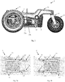
- Figures 1a, 1b show perspective views of a wheelchair 1, 1' according to embodiments of the invention configured in a front wheel drive mode and in a rear wheel drive mode.
- the wheelchair 1 comprises two modular wheel assemblies 3, 3', where one of the modular wheel assemblies 3, 3' is connected to each side of the wheelchair 1 at a modular power chair base 5.
- the modular wheel assemblies 3, 3' comprise a frame member 7, 7' comprising a castor wheel 9, 9' and a drive wheel 11, 11' each.
- the modular wheel assemblies 3, 3' also comprise a castor arm 13, 13' with a castor fork 15, 15' each for supporting the respective castor wheel 9, 9'.
- the wheelchair 1, 1' comprises a motor mount arm 17, 17' that carries a motor 19, 19' and the drive wheel 11, 11'.
- the wheelchair 1,1' shown in figures 1a, 1b comprises a seat 21 mounted on top of the modular power chair base 5.
- Modular wheel assemblies 3, 3' according to a first configuration and of a second configuration are mounted on the modular power chair base 5.
- the drive wheel 11 is arranged offset to a first side of the frame member 7 out of alignment of a centerline of the frame member 7 so that the drive wheel 11 sticks out to the side of the wheelchair 1.
- the drive wheel 11' sticks out to the opposite side of the wheelchair 1 as it can be best seen from figure 1b .
- the skilled person would know that the invention could be also carried out when two identical wheels assemblies are installed on both sides of the modular power chair base, where the drive wheels are essentially arranged in alignment with the centerline of the frame member.
- the wheelchair 1 has the larger drive wheels 11, 11' at the front.
- the centre of gravity is more forward of the centre of the modular power chair base 5, i.e. near the drive wheels 11, 11' to ensure traction between the tires and ground.
- the wheelchair 1 tends to 'fish tail'. This is an unintended motion of the rear of the wheelchair 1 oscillating left/right.
- Small directional corrections at the drive wheels 11, 11' or changes in direction caused by the road surface are exaggerated at the rear extremity of the wheelchair 1.
- castor flutter is the rapid and uncontrolled oscillation of the castor wheels 9, 9'.
- Figure 1b essentially shows the arrangement of figure 1a , however, the the two modular wheel assemblies 3, 3' are swapped on the sides of the of the modular power chair base 5.
- the wheelchair 1' is adapted to be converted from a front wheel drive mode to a rear wheel drive mode (and vice versa) by swapping the two modular wheel assemblies 3, 3' on the sides of the of the modular power chair base 5.
- the larger drive wheels 11, 11' are at the rear. Therefore the castor wheels 9, 9' and their support are located at the front of the wheelchair 1', in the same area where the footrests (not shown in figures 1a, 1b ) could be located.
- Figure 2 shows a side view of a modular wheel assembly 3 according to one embodiment of the invention.
- the shown modular wheel assembly could be one of the modular wheel assemblies 3 shown in figures 1a, 1b .
- the modular wheel assembly 3 comprises a first connection member 23a, and a second connection member 23b.
- the position of the second connection member 23b is offset from the position of the first connection member 23a.
- the connection members 23a, 23b could be offset in the same horizontal plane by a distance ranging from 20mm to 100mm, preferably offset by a distance of 20mm.
- Both connection members 23a, 23b are suitable to be connected to the connection point on the modular power chair base 5 of the wheelchair. However, depending on whether a front wheel drive mode or a rear wheel drive mode is desired by the user, only one of the connection members 23a, 23b is connected to the connection point.
- the first connection member 23a is arranged on the frame member 7 so that the drive wheel 11 is positioned away from the center of the modular power chair base 5 when the modular wheel assembly 3 is connected to the connection point on the modular power chair base 5 of the wheelchair by the first connection member 23a
- the second connecting 23b member is arranged on the frame member 7 so that the drive wheel 11 is positioned towards the centre of the modular power chair base 5 when the modular wheel assembly 3 is connected to the connection point on the modular power chair base 5 of the wheelchair by the second connection member 23b.
- a connection of the first connection member 23a to the connection point on the modular power chair base 5 corresponds to a front wheel drive mode of the wheelchair
- a connection of the second connection member 23b to the connection point corresponds to a rear wheel drive mode of the wheelchair.
- two connection points arranged on each side of the modular power base 5 that connect to one connection member on the modular power chair base there could be alternatively, i.e. to achieve the same effect, two connection points arranged on each side of the modular power base 5 that connect to one connection member on the modular power chair base.
- Figures 3a, 3b are top views of a wheelchair 1, 1' according to embodiments of the invention configured in a front wheel drive mode and in a rear wheel drive mode.
- the shown wheelchairs 1, 1' and modular wheel assemblies 3, 3' could be the wheelchairs and modular wheel assemblies that are shown in the previous figures.
- Figure 3a shows the wheelchair 1 in a front wheel drive mode as also shown in figure 1a
- figure 3b shows the wheelchair 1' in a rear wheel drive mode as also shown in figure 1b .
- Both figures 3a, 3b show that the castor arms 13, 13' could be also spaced, e.g. bend, to a side of the frame members 7, 7' to carry the respective castor wheel 9, 9' out of alignment of the centerline of the respective frame member 7, 7'.
- the castor arms 13, 13' shaped as shown in figures 3a, 3b allows to achieve small lateral dimensions between the castor wheels 11, 11' when the wheelchair 1 is configured in the front wheel drive mode to provide a better, i.e. more stable, driving performance.
- the modular wheel assemblies 3, 3' are swapped around on the modular power base of the wheelchair 1' as shown in figure 3b , i.e. the wheelchair 1' is configured in the rear wheel drive mode, larger lateral dimensions between the castor wheels 11, 11' provides more space to accommodate the castors and footrests (not shown in figures 3a, 3b ).
- Figures 4a, 4b are side views of a wheelchair 1, 1' according to embodiments of the invention configured in a front wheel drive mode and in a rear wheel drive mode, and having a foot support 25 installed.
- Wheelchairs normally provide a leg/foot support, these come in two general formats:
- the foot supports 25 are located on the front edge of the wheelchair seat 21, the clinical aim is to provide a 90° knee angle, i.e. the angle between the thigh and lower leg.
- the overall length of the wheelchair 1,1' i.e. to minimize the turning circle, and to provide a stable chair, i.e. one that does not tip forward, the seat front edge and the drive wheels usual coincide. Therefore the usual footrest used on front wheel drive wheelchairs 1 are Centre mount version as these avoid collisions with the drive wheels.
- the design according to the invention allows to use one common foot support 25 that can be used for both modes.
Landscapes
- Health & Medical Sciences (AREA)
- Life Sciences & Earth Sciences (AREA)
- Animal Behavior & Ethology (AREA)
- General Health & Medical Sciences (AREA)
- Public Health (AREA)
- Veterinary Medicine (AREA)
- Handcart (AREA)
- Arrangement Or Mounting Of Propulsion Units For Vehicles (AREA)
Applications Claiming Priority (1)
| Application Number | Priority Date | Filing Date | Title |
|---|---|---|---|
| DE102016124424.4A DE102016124424A1 (de) | 2016-12-14 | 2016-12-14 | Modulare Radanordnung für einen Rollstuhl |
Publications (2)
| Publication Number | Publication Date |
|---|---|
| EP3351228A1 true EP3351228A1 (fr) | 2018-07-25 |
| EP3351228B1 EP3351228B1 (fr) | 2019-09-11 |
Family
ID=60569832
Family Applications (1)
| Application Number | Title | Priority Date | Filing Date |
|---|---|---|---|
| EP17205230.0A Active EP3351228B1 (fr) | 2016-12-14 | 2017-12-04 | Ensemble de roue modulaire destiné à un fauteuil roulant |
Country Status (2)
| Country | Link |
|---|---|
| EP (1) | EP3351228B1 (fr) |
| DE (1) | DE102016124424A1 (fr) |
Families Citing this family (2)
| Publication number | Priority date | Publication date | Assignee | Title |
|---|---|---|---|---|
| EP4302741B1 (fr) | 2022-07-07 | 2025-01-29 | Permobil AB | Fauteuil roulant à roue motrice centrale avec capacité de se tenir debout |
| PL4335423T3 (pl) * | 2022-09-08 | 2025-08-18 | Asian Prime Sources Limited | Terenowy elektryczny wózek inwalidzki i odpowiedni zespół |
Citations (4)
| Publication number | Priority date | Publication date | Assignee | Title |
|---|---|---|---|---|
| US5156226A (en) * | 1988-10-05 | 1992-10-20 | Everest & Jennings, Inc. | Modular power drive wheelchair |
| US6290011B1 (en) | 1999-11-01 | 2001-09-18 | Burke Mobility Products, Inc. | Front wheel/rear wheel drive convertible wheelchair |
| EP1522293A2 (fr) * | 2003-10-08 | 2005-04-13 | Pride Mobility Products Corporation | Fauteuil roulant motorisé transportable |
| US20150175227A1 (en) * | 2013-12-25 | 2015-06-25 | Hota Industrial Mfg. Co., Ltd. | Modular mobile vehicle with an adjustable wheelbase |
-
2016
- 2016-12-14 DE DE102016124424.4A patent/DE102016124424A1/de not_active Withdrawn
-
2017
- 2017-12-04 EP EP17205230.0A patent/EP3351228B1/fr active Active
Patent Citations (4)
| Publication number | Priority date | Publication date | Assignee | Title |
|---|---|---|---|---|
| US5156226A (en) * | 1988-10-05 | 1992-10-20 | Everest & Jennings, Inc. | Modular power drive wheelchair |
| US6290011B1 (en) | 1999-11-01 | 2001-09-18 | Burke Mobility Products, Inc. | Front wheel/rear wheel drive convertible wheelchair |
| EP1522293A2 (fr) * | 2003-10-08 | 2005-04-13 | Pride Mobility Products Corporation | Fauteuil roulant motorisé transportable |
| US20150175227A1 (en) * | 2013-12-25 | 2015-06-25 | Hota Industrial Mfg. Co., Ltd. | Modular mobile vehicle with an adjustable wheelbase |
Also Published As
| Publication number | Publication date |
|---|---|
| EP3351228B1 (fr) | 2019-09-11 |
| DE102016124424A1 (de) | 2018-06-14 |
Similar Documents
| Publication | Publication Date | Title |
|---|---|---|
| US6341657B1 (en) | Suspension for central drive vehicle | |
| US4132435A (en) | Steerable wheeled vehicle | |
| EP2101704B1 (fr) | Fauteuil roulant ayant des bras de suspension pour roues | |
| CN103068352B (zh) | 电动中间轮驱动轮椅 | |
| US4513832A (en) | Wheeled chassis | |
| EP0677285B1 (fr) | Fauteuil roulant motorisé avec centre de gravité réglable et avec suspension indépendant | |
| US11027416B2 (en) | Two-wheeled self-balancing robot | |
| US7484746B2 (en) | Wheeled conveyance | |
| CN106163848A (zh) | 电力推动车辆 | |
| EP3137033B1 (fr) | Fauteuil roulant motorisé | |
| US20170056259A1 (en) | Powered wheelchair | |
| EP3351228A1 (fr) | Ensemble de roue modulaire destiné à un fauteuil roulant | |
| US8820454B2 (en) | Motorized wheelchair | |
| ES2619429T3 (es) | Triciclo | |
| US20150053490A1 (en) | Battery powered all terrain wheelchair | |
| US11382808B2 (en) | Wheelchair | |
| EP3348248B1 (fr) | Fauteuil roulant | |
| US6250661B1 (en) | Tilt system for a powered wheelchair seat | |
| CN112618182B (zh) | 轮椅助行器 | |
| JP2014091040A (ja) | スポーツ用のガード付き電動車椅子 | |
| EP2829258B1 (fr) | Structure de fauteuil roulant et ensemble de suspension | |
| US10568788B2 (en) | Mid-wheel drive wheelchair and seat unit | |
| CN109789047B (zh) | 用于移动辅助设备和电动轮椅的底盘 | |
| EP3782595B1 (fr) | Fauteuil roulant | |
| JP2012030700A (ja) | サイドカー及びサイドカー付き自転車 |
Legal Events
| Date | Code | Title | Description |
|---|---|---|---|
| PUAI | Public reference made under article 153(3) epc to a published international application that has entered the european phase |
Free format text: ORIGINAL CODE: 0009012 |
|
| STAA | Information on the status of an ep patent application or granted ep patent |
Free format text: STATUS: THE APPLICATION HAS BEEN PUBLISHED |
|
| AK | Designated contracting states |
Kind code of ref document: A1 Designated state(s): AL AT BE BG CH CY CZ DE DK EE ES FI FR GB GR HR HU IE IS IT LI LT LU LV MC MK MT NL NO PL PT RO RS SE SI SK SM TR |
|
| AX | Request for extension of the european patent |
Extension state: BA ME |
|
| STAA | Information on the status of an ep patent application or granted ep patent |
Free format text: STATUS: REQUEST FOR EXAMINATION WAS MADE |
|
| 17P | Request for examination filed |
Effective date: 20181025 |
|
| RBV | Designated contracting states (corrected) |
Designated state(s): AL AT BE BG CH CY CZ DE DK EE ES FI FR GB GR HR HU IE IS IT LI LT LU LV MC MK MT NL NO PL PT RO RS SE SI SK SM TR |
|
| RIC1 | Information provided on ipc code assigned before grant |
Ipc: A61G 5/04 20130101AFI20190306BHEP |
|
| GRAP | Despatch of communication of intention to grant a patent |
Free format text: ORIGINAL CODE: EPIDOSNIGR1 |
|
| STAA | Information on the status of an ep patent application or granted ep patent |
Free format text: STATUS: GRANT OF PATENT IS INTENDED |
|
| INTG | Intention to grant announced |
Effective date: 20190415 |
|
| GRAS | Grant fee paid |
Free format text: ORIGINAL CODE: EPIDOSNIGR3 |
|
| GRAA | (expected) grant |
Free format text: ORIGINAL CODE: 0009210 |
|
| STAA | Information on the status of an ep patent application or granted ep patent |
Free format text: STATUS: THE PATENT HAS BEEN GRANTED |
|
| AK | Designated contracting states |
Kind code of ref document: B1 Designated state(s): AL AT BE BG CH CY CZ DE DK EE ES FI FR GB GR HR HU IE IS IT LI LT LU LV MC MK MT NL NO PL PT RO RS SE SI SK SM TR |
|
| REG | Reference to a national code |
Ref country code: GB Ref legal event code: FG4D |
|
| REG | Reference to a national code |
Ref country code: CH Ref legal event code: EP |
|
| REG | Reference to a national code |
Ref country code: AT Ref legal event code: REF Ref document number: 1177540 Country of ref document: AT Kind code of ref document: T Effective date: 20190915 |
|
| REG | Reference to a national code |
Ref country code: DE Ref legal event code: R096 Ref document number: 602017006970 Country of ref document: DE Ref country code: IE Ref legal event code: FG4D |
|
| REG | Reference to a national code |
Ref country code: NL Ref legal event code: FP |
|
| REG | Reference to a national code |
Ref country code: LT Ref legal event code: MG4D Ref country code: NO Ref legal event code: T2 Effective date: 20190911 |
|
| PG25 | Lapsed in a contracting state [announced via postgrant information from national office to epo] |
Ref country code: FI Free format text: LAPSE BECAUSE OF FAILURE TO SUBMIT A TRANSLATION OF THE DESCRIPTION OR TO PAY THE FEE WITHIN THE PRESCRIBED TIME-LIMIT Effective date: 20190911 Ref country code: LT Free format text: LAPSE BECAUSE OF FAILURE TO SUBMIT A TRANSLATION OF THE DESCRIPTION OR TO PAY THE FEE WITHIN THE PRESCRIBED TIME-LIMIT Effective date: 20190911 Ref country code: HR Free format text: LAPSE BECAUSE OF FAILURE TO SUBMIT A TRANSLATION OF THE DESCRIPTION OR TO PAY THE FEE WITHIN THE PRESCRIBED TIME-LIMIT Effective date: 20190911 Ref country code: SE Free format text: LAPSE BECAUSE OF FAILURE TO SUBMIT A TRANSLATION OF THE DESCRIPTION OR TO PAY THE FEE WITHIN THE PRESCRIBED TIME-LIMIT Effective date: 20190911 Ref country code: BG Free format text: LAPSE BECAUSE OF FAILURE TO SUBMIT A TRANSLATION OF THE DESCRIPTION OR TO PAY THE FEE WITHIN THE PRESCRIBED TIME-LIMIT Effective date: 20191211 |
|
| PG25 | Lapsed in a contracting state [announced via postgrant information from national office to epo] |
Ref country code: ES Free format text: LAPSE BECAUSE OF FAILURE TO SUBMIT A TRANSLATION OF THE DESCRIPTION OR TO PAY THE FEE WITHIN THE PRESCRIBED TIME-LIMIT Effective date: 20190911 Ref country code: GR Free format text: LAPSE BECAUSE OF FAILURE TO SUBMIT A TRANSLATION OF THE DESCRIPTION OR TO PAY THE FEE WITHIN THE PRESCRIBED TIME-LIMIT Effective date: 20191212 Ref country code: LV Free format text: LAPSE BECAUSE OF FAILURE TO SUBMIT A TRANSLATION OF THE DESCRIPTION OR TO PAY THE FEE WITHIN THE PRESCRIBED TIME-LIMIT Effective date: 20190911 Ref country code: RS Free format text: LAPSE BECAUSE OF FAILURE TO SUBMIT A TRANSLATION OF THE DESCRIPTION OR TO PAY THE FEE WITHIN THE PRESCRIBED TIME-LIMIT Effective date: 20190911 Ref country code: AL Free format text: LAPSE BECAUSE OF FAILURE TO SUBMIT A TRANSLATION OF THE DESCRIPTION OR TO PAY THE FEE WITHIN THE PRESCRIBED TIME-LIMIT Effective date: 20190911 |
|
| REG | Reference to a national code |
Ref country code: AT Ref legal event code: MK05 Ref document number: 1177540 Country of ref document: AT Kind code of ref document: T Effective date: 20190911 |
|
| PG25 | Lapsed in a contracting state [announced via postgrant information from national office to epo] |
Ref country code: EE Free format text: LAPSE BECAUSE OF FAILURE TO SUBMIT A TRANSLATION OF THE DESCRIPTION OR TO PAY THE FEE WITHIN THE PRESCRIBED TIME-LIMIT Effective date: 20190911 Ref country code: PL Free format text: LAPSE BECAUSE OF FAILURE TO SUBMIT A TRANSLATION OF THE DESCRIPTION OR TO PAY THE FEE WITHIN THE PRESCRIBED TIME-LIMIT Effective date: 20190911 Ref country code: IT Free format text: LAPSE BECAUSE OF FAILURE TO SUBMIT A TRANSLATION OF THE DESCRIPTION OR TO PAY THE FEE WITHIN THE PRESCRIBED TIME-LIMIT Effective date: 20190911 Ref country code: RO Free format text: LAPSE BECAUSE OF FAILURE TO SUBMIT A TRANSLATION OF THE DESCRIPTION OR TO PAY THE FEE WITHIN THE PRESCRIBED TIME-LIMIT Effective date: 20190911 Ref country code: AT Free format text: LAPSE BECAUSE OF FAILURE TO SUBMIT A TRANSLATION OF THE DESCRIPTION OR TO PAY THE FEE WITHIN THE PRESCRIBED TIME-LIMIT Effective date: 20190911 Ref country code: PT Free format text: LAPSE BECAUSE OF FAILURE TO SUBMIT A TRANSLATION OF THE DESCRIPTION OR TO PAY THE FEE WITHIN THE PRESCRIBED TIME-LIMIT Effective date: 20200113 |
|
| PG25 | Lapsed in a contracting state [announced via postgrant information from national office to epo] |
Ref country code: SK Free format text: LAPSE BECAUSE OF FAILURE TO SUBMIT A TRANSLATION OF THE DESCRIPTION OR TO PAY THE FEE WITHIN THE PRESCRIBED TIME-LIMIT Effective date: 20190911 Ref country code: SM Free format text: LAPSE BECAUSE OF FAILURE TO SUBMIT A TRANSLATION OF THE DESCRIPTION OR TO PAY THE FEE WITHIN THE PRESCRIBED TIME-LIMIT Effective date: 20190911 Ref country code: IS Free format text: LAPSE BECAUSE OF FAILURE TO SUBMIT A TRANSLATION OF THE DESCRIPTION OR TO PAY THE FEE WITHIN THE PRESCRIBED TIME-LIMIT Effective date: 20200224 Ref country code: CZ Free format text: LAPSE BECAUSE OF FAILURE TO SUBMIT A TRANSLATION OF THE DESCRIPTION OR TO PAY THE FEE WITHIN THE PRESCRIBED TIME-LIMIT Effective date: 20190911 |
|
| REG | Reference to a national code |
Ref country code: DE Ref legal event code: R097 Ref document number: 602017006970 Country of ref document: DE |
|
| PLBE | No opposition filed within time limit |
Free format text: ORIGINAL CODE: 0009261 |
|
| STAA | Information on the status of an ep patent application or granted ep patent |
Free format text: STATUS: NO OPPOSITION FILED WITHIN TIME LIMIT |
|
| PG2D | Information on lapse in contracting state deleted |
Ref country code: IS |
|
| PG25 | Lapsed in a contracting state [announced via postgrant information from national office to epo] |
Ref country code: DK Free format text: LAPSE BECAUSE OF FAILURE TO SUBMIT A TRANSLATION OF THE DESCRIPTION OR TO PAY THE FEE WITHIN THE PRESCRIBED TIME-LIMIT Effective date: 20190911 Ref country code: IS Free format text: LAPSE BECAUSE OF FAILURE TO SUBMIT A TRANSLATION OF THE DESCRIPTION OR TO PAY THE FEE WITHIN THE PRESCRIBED TIME-LIMIT Effective date: 20200112 |
|
| 26N | No opposition filed |
Effective date: 20200615 |
|
| REG | Reference to a national code |
Ref country code: BE Ref legal event code: MM Effective date: 20191231 |
|
| PG25 | Lapsed in a contracting state [announced via postgrant information from national office to epo] |
Ref country code: SI Free format text: LAPSE BECAUSE OF FAILURE TO SUBMIT A TRANSLATION OF THE DESCRIPTION OR TO PAY THE FEE WITHIN THE PRESCRIBED TIME-LIMIT Effective date: 20190911 Ref country code: MC Free format text: LAPSE BECAUSE OF FAILURE TO SUBMIT A TRANSLATION OF THE DESCRIPTION OR TO PAY THE FEE WITHIN THE PRESCRIBED TIME-LIMIT Effective date: 20190911 |
|
| PG25 | Lapsed in a contracting state [announced via postgrant information from national office to epo] |
Ref country code: LU Free format text: LAPSE BECAUSE OF NON-PAYMENT OF DUE FEES Effective date: 20191204 Ref country code: IE Free format text: LAPSE BECAUSE OF NON-PAYMENT OF DUE FEES Effective date: 20191204 |
|
| PG25 | Lapsed in a contracting state [announced via postgrant information from national office to epo] |
Ref country code: BE Free format text: LAPSE BECAUSE OF NON-PAYMENT OF DUE FEES Effective date: 20191231 |
|
| PG25 | Lapsed in a contracting state [announced via postgrant information from national office to epo] |
Ref country code: CY Free format text: LAPSE BECAUSE OF FAILURE TO SUBMIT A TRANSLATION OF THE DESCRIPTION OR TO PAY THE FEE WITHIN THE PRESCRIBED TIME-LIMIT Effective date: 20190911 |
|
| PG25 | Lapsed in a contracting state [announced via postgrant information from national office to epo] |
Ref country code: HU Free format text: LAPSE BECAUSE OF FAILURE TO SUBMIT A TRANSLATION OF THE DESCRIPTION OR TO PAY THE FEE WITHIN THE PRESCRIBED TIME-LIMIT; INVALID AB INITIO Effective date: 20171204 Ref country code: MT Free format text: LAPSE BECAUSE OF FAILURE TO SUBMIT A TRANSLATION OF THE DESCRIPTION OR TO PAY THE FEE WITHIN THE PRESCRIBED TIME-LIMIT Effective date: 20190911 |
|
| REG | Reference to a national code |
Ref country code: CH Ref legal event code: PL |
|
| PG25 | Lapsed in a contracting state [announced via postgrant information from national office to epo] |
Ref country code: LI Free format text: LAPSE BECAUSE OF NON-PAYMENT OF DUE FEES Effective date: 20201231 Ref country code: CH Free format text: LAPSE BECAUSE OF NON-PAYMENT OF DUE FEES Effective date: 20201231 |
|
| PG25 | Lapsed in a contracting state [announced via postgrant information from national office to epo] |
Ref country code: TR Free format text: LAPSE BECAUSE OF FAILURE TO SUBMIT A TRANSLATION OF THE DESCRIPTION OR TO PAY THE FEE WITHIN THE PRESCRIBED TIME-LIMIT Effective date: 20190911 |
|
| PG25 | Lapsed in a contracting state [announced via postgrant information from national office to epo] |
Ref country code: MK Free format text: LAPSE BECAUSE OF FAILURE TO SUBMIT A TRANSLATION OF THE DESCRIPTION OR TO PAY THE FEE WITHIN THE PRESCRIBED TIME-LIMIT Effective date: 20190911 |
|
| GBPC | Gb: european patent ceased through non-payment of renewal fee |
Effective date: 20211204 |
|
| PG25 | Lapsed in a contracting state [announced via postgrant information from national office to epo] |
Ref country code: GB Free format text: LAPSE BECAUSE OF NON-PAYMENT OF DUE FEES Effective date: 20211204 |
|
| P01 | Opt-out of the competence of the unified patent court (upc) registered |
Effective date: 20230619 |
|
| PGFP | Annual fee paid to national office [announced via postgrant information from national office to epo] |
Ref country code: NO Payment date: 20251216 Year of fee payment: 9 |
|
| PGFP | Annual fee paid to national office [announced via postgrant information from national office to epo] |
Ref country code: FR Payment date: 20251218 Year of fee payment: 9 Ref country code: NL Payment date: 20251217 Year of fee payment: 9 |
|
| PGFP | Annual fee paid to national office [announced via postgrant information from national office to epo] |
Ref country code: DE Payment date: 20251222 Year of fee payment: 9 |