EP3351390A1 - Verfahren zur herstellung eines flüssigkeitsausstosskopfes - Google Patents
Verfahren zur herstellung eines flüssigkeitsausstosskopfes Download PDFInfo
- Publication number
- EP3351390A1 EP3351390A1 EP17206704.3A EP17206704A EP3351390A1 EP 3351390 A1 EP3351390 A1 EP 3351390A1 EP 17206704 A EP17206704 A EP 17206704A EP 3351390 A1 EP3351390 A1 EP 3351390A1
- Authority
- EP
- European Patent Office
- Prior art keywords
- hole
- preliminary
- etching
- liquid ejecting
- forming
- Prior art date
- Legal status (The legal status is an assumption and is not a legal conclusion. Google has not performed a legal analysis and makes no representation as to the accuracy of the status listed.)
- Withdrawn
Links
- 239000007788 liquid Substances 0.000 title claims abstract description 104
- 238000004519 manufacturing process Methods 0.000 title claims abstract description 34
- 238000005530 etching Methods 0.000 claims abstract description 79
- 239000000758 substrate Substances 0.000 claims abstract description 66
- 238000004891 communication Methods 0.000 claims abstract description 63
- 238000000034 method Methods 0.000 claims abstract description 9
- 238000000708 deep reactive-ion etching Methods 0.000 claims description 4
- 230000000149 penetrating effect Effects 0.000 claims description 2
- 238000007665 sagging Methods 0.000 description 29
- 239000000463 material Substances 0.000 description 7
- 238000003860 storage Methods 0.000 description 6
- 230000008569 process Effects 0.000 description 5
- 238000007789 sealing Methods 0.000 description 5
- 230000015572 biosynthetic process Effects 0.000 description 4
- 239000013078 crystal Substances 0.000 description 4
- 238000007639 printing Methods 0.000 description 4
- 230000001681 protective effect Effects 0.000 description 4
- 239000002210 silicon-based material Substances 0.000 description 4
- 239000000243 solution Substances 0.000 description 4
- XUIMIQQOPSSXEZ-UHFFFAOYSA-N Silicon Chemical compound [Si] XUIMIQQOPSSXEZ-UHFFFAOYSA-N 0.000 description 3
- 239000000853 adhesive Substances 0.000 description 3
- 230000001070 adhesive effect Effects 0.000 description 3
- 238000010586 diagram Methods 0.000 description 3
- 238000000465 moulding Methods 0.000 description 3
- 238000001020 plasma etching Methods 0.000 description 3
- 239000011347 resin Substances 0.000 description 3
- 229920005989 resin Polymers 0.000 description 3
- 229910052710 silicon Inorganic materials 0.000 description 3
- 239000010703 silicon Substances 0.000 description 3
- 238000000347 anisotropic wet etching Methods 0.000 description 2
- 238000007599 discharging Methods 0.000 description 2
- 238000012986 modification Methods 0.000 description 2
- 230000004048 modification Effects 0.000 description 2
- 230000007723 transport mechanism Effects 0.000 description 2
- 238000009623 Bosch process Methods 0.000 description 1
- KWYUFKZDYYNOTN-UHFFFAOYSA-M Potassium hydroxide Chemical compound [OH-].[K+] KWYUFKZDYYNOTN-UHFFFAOYSA-M 0.000 description 1
- VYPSYNLAJGMNEJ-UHFFFAOYSA-N Silicium dioxide Chemical compound O=[Si]=O VYPSYNLAJGMNEJ-UHFFFAOYSA-N 0.000 description 1
- 239000007864 aqueous solution Substances 0.000 description 1
- 230000008901 benefit Effects 0.000 description 1
- 230000008859 change Effects 0.000 description 1
- 239000004020 conductor Substances 0.000 description 1
- 238000001312 dry etching Methods 0.000 description 1
- 238000010438 heat treatment Methods 0.000 description 1
- 238000001746 injection moulding Methods 0.000 description 1
- 230000001678 irradiating effect Effects 0.000 description 1
- 238000005304 joining Methods 0.000 description 1
- 239000004973 liquid crystal related substance Substances 0.000 description 1
- 150000004767 nitrides Chemical class 0.000 description 1
- 230000035515 penetration Effects 0.000 description 1
- 229910052814 silicon oxide Inorganic materials 0.000 description 1
- 230000032258 transport Effects 0.000 description 1
- 238000001039 wet etching Methods 0.000 description 1
Images


Classifications
-
- B—PERFORMING OPERATIONS; TRANSPORTING
- B41—PRINTING; LINING MACHINES; TYPEWRITERS; STAMPS
- B41J—TYPEWRITERS; SELECTIVE PRINTING MECHANISMS, i.e. MECHANISMS PRINTING OTHERWISE THAN FROM A FORME; CORRECTION OF TYPOGRAPHICAL ERRORS
- B41J2/00—Typewriters or selective printing mechanisms characterised by the printing or marking process for which they are designed
- B41J2/005—Typewriters or selective printing mechanisms characterised by the printing or marking process for which they are designed characterised by bringing liquid or particles selectively into contact with a printing material
- B41J2/01—Ink jet
- B41J2/135—Nozzles
- B41J2/16—Production of nozzles
- B41J2/1607—Production of print heads with piezoelectric elements
- B41J2/1612—Production of print heads with piezoelectric elements of stacked structure type, deformed by compression/extension and disposed on a diaphragm
-
- B—PERFORMING OPERATIONS; TRANSPORTING
- B41—PRINTING; LINING MACHINES; TYPEWRITERS; STAMPS
- B41J—TYPEWRITERS; SELECTIVE PRINTING MECHANISMS, i.e. MECHANISMS PRINTING OTHERWISE THAN FROM A FORME; CORRECTION OF TYPOGRAPHICAL ERRORS
- B41J2/00—Typewriters or selective printing mechanisms characterised by the printing or marking process for which they are designed
- B41J2/005—Typewriters or selective printing mechanisms characterised by the printing or marking process for which they are designed characterised by bringing liquid or particles selectively into contact with a printing material
- B41J2/01—Ink jet
- B41J2/135—Nozzles
- B41J2/14—Structure thereof only for on-demand ink jet heads
- B41J2/14201—Structure of print heads with piezoelectric elements
- B41J2/14233—Structure of print heads with piezoelectric elements of film type, deformed by bending and disposed on a diaphragm
-
- B—PERFORMING OPERATIONS; TRANSPORTING
- B41—PRINTING; LINING MACHINES; TYPEWRITERS; STAMPS
- B41J—TYPEWRITERS; SELECTIVE PRINTING MECHANISMS, i.e. MECHANISMS PRINTING OTHERWISE THAN FROM A FORME; CORRECTION OF TYPOGRAPHICAL ERRORS
- B41J2/00—Typewriters or selective printing mechanisms characterised by the printing or marking process for which they are designed
- B41J2/005—Typewriters or selective printing mechanisms characterised by the printing or marking process for which they are designed characterised by bringing liquid or particles selectively into contact with a printing material
- B41J2/01—Ink jet
- B41J2/135—Nozzles
- B41J2/16—Production of nozzles
- B41J2/1607—Production of print heads with piezoelectric elements
- B41J2/161—Production of print heads with piezoelectric elements of film type, deformed by bending and disposed on a diaphragm
-
- B—PERFORMING OPERATIONS; TRANSPORTING
- B41—PRINTING; LINING MACHINES; TYPEWRITERS; STAMPS
- B41J—TYPEWRITERS; SELECTIVE PRINTING MECHANISMS, i.e. MECHANISMS PRINTING OTHERWISE THAN FROM A FORME; CORRECTION OF TYPOGRAPHICAL ERRORS
- B41J2/00—Typewriters or selective printing mechanisms characterised by the printing or marking process for which they are designed
- B41J2/005—Typewriters or selective printing mechanisms characterised by the printing or marking process for which they are designed characterised by bringing liquid or particles selectively into contact with a printing material
- B41J2/01—Ink jet
- B41J2/135—Nozzles
- B41J2/16—Production of nozzles
- B41J2/1621—Manufacturing processes
- B41J2/1626—Manufacturing processes etching
- B41J2/1628—Manufacturing processes etching dry etching
-
- B—PERFORMING OPERATIONS; TRANSPORTING
- B41—PRINTING; LINING MACHINES; TYPEWRITERS; STAMPS
- B41J—TYPEWRITERS; SELECTIVE PRINTING MECHANISMS, i.e. MECHANISMS PRINTING OTHERWISE THAN FROM A FORME; CORRECTION OF TYPOGRAPHICAL ERRORS
- B41J2/00—Typewriters or selective printing mechanisms characterised by the printing or marking process for which they are designed
- B41J2/005—Typewriters or selective printing mechanisms characterised by the printing or marking process for which they are designed characterised by bringing liquid or particles selectively into contact with a printing material
- B41J2/01—Ink jet
- B41J2/135—Nozzles
- B41J2/16—Production of nozzles
- B41J2/1621—Manufacturing processes
- B41J2/1626—Manufacturing processes etching
- B41J2/1629—Manufacturing processes etching wet etching
-
- B—PERFORMING OPERATIONS; TRANSPORTING
- B41—PRINTING; LINING MACHINES; TYPEWRITERS; STAMPS
- B41J—TYPEWRITERS; SELECTIVE PRINTING MECHANISMS, i.e. MECHANISMS PRINTING OTHERWISE THAN FROM A FORME; CORRECTION OF TYPOGRAPHICAL ERRORS
- B41J2/00—Typewriters or selective printing mechanisms characterised by the printing or marking process for which they are designed
- B41J2/005—Typewriters or selective printing mechanisms characterised by the printing or marking process for which they are designed characterised by bringing liquid or particles selectively into contact with a printing material
- B41J2/01—Ink jet
- B41J2/135—Nozzles
- B41J2/16—Production of nozzles
- B41J2/1621—Manufacturing processes
- B41J2/1632—Manufacturing processes machining
- B41J2/1634—Manufacturing processes machining laser machining
-
- B—PERFORMING OPERATIONS; TRANSPORTING
- B41—PRINTING; LINING MACHINES; TYPEWRITERS; STAMPS
- B41J—TYPEWRITERS; SELECTIVE PRINTING MECHANISMS, i.e. MECHANISMS PRINTING OTHERWISE THAN FROM A FORME; CORRECTION OF TYPOGRAPHICAL ERRORS
- B41J2/00—Typewriters or selective printing mechanisms characterised by the printing or marking process for which they are designed
- B41J2/005—Typewriters or selective printing mechanisms characterised by the printing or marking process for which they are designed characterised by bringing liquid or particles selectively into contact with a printing material
- B41J2/01—Ink jet
- B41J2/135—Nozzles
- B41J2/14—Structure thereof only for on-demand ink jet heads
- B41J2/14201—Structure of print heads with piezoelectric elements
- B41J2/14233—Structure of print heads with piezoelectric elements of film type, deformed by bending and disposed on a diaphragm
- B41J2002/14241—Structure of print heads with piezoelectric elements of film type, deformed by bending and disposed on a diaphragm having a cover around the piezoelectric thin film element
-
- B—PERFORMING OPERATIONS; TRANSPORTING
- B41—PRINTING; LINING MACHINES; TYPEWRITERS; STAMPS
- B41J—TYPEWRITERS; SELECTIVE PRINTING MECHANISMS, i.e. MECHANISMS PRINTING OTHERWISE THAN FROM A FORME; CORRECTION OF TYPOGRAPHICAL ERRORS
- B41J2202/00—Embodiments of or processes related to ink-jet or thermal heads
- B41J2202/01—Embodiments of or processes related to ink-jet heads
- B41J2202/03—Specific materials used
-
- B—PERFORMING OPERATIONS; TRANSPORTING
- B41—PRINTING; LINING MACHINES; TYPEWRITERS; STAMPS
- B41J—TYPEWRITERS; SELECTIVE PRINTING MECHANISMS, i.e. MECHANISMS PRINTING OTHERWISE THAN FROM A FORME; CORRECTION OF TYPOGRAPHICAL ERRORS
- B41J2202/00—Embodiments of or processes related to ink-jet or thermal heads
- B41J2202/01—Embodiments of or processes related to ink-jet heads
- B41J2202/22—Manufacturing print heads
Definitions
- the present invention relates to a method of manufacturing a liquid ejecting head that ejects liquid such as ink.
- a liquid ejecting head that ejects liquid from a nozzle by supplying a liquid such as ink to a pressure chamber and causing a pressure change in the liquid in the pressure chamber is formed by stacking a pressure chamber substrate in which a pressure chamber is formed, a flow channel substrate in which a liquid flow channel and a liquid chamber are formed, and the like.
- a flow channel including a concave portion (step wall surfaces) and hole portions (reservoir portions) is formed in the flow channel substrate (reservoir forming substrate) of JP-A-2007-98813 .
- the flow channel substrate in JP-A-2007-98813 is a substrate composed of silicon, and the flow channel including a concave portion and hole portions is formed by two-step etching.
- the hole portions are formed by etching in a first step, and the concave portion is formed by etching in a second step.
- a sagging surface is formed at the edge portion of openings of the flow channel and is inclined in such a manner that the openings of the flow channel widen outward. Consequently, when the hole portions and the concave portion are formed by two-step etching as in JP-A-2007-98813 , in etching of the concave portion in the second step, the sagging surface at the edge of the openings of the hole portions formed by etching in the first step is further etched and there is a possibility that the openings of the hole portions become further widened.
- An advantage of some aspects of the invention is that a flow channel having a concave portion and hole portions is formed by one-step etching and sagging of the openings of the hole portions is suppressed.
- a method of manufacturing a liquid ejecting head that includes a communication substrate on which a pressure chamber substrate in which a pressure chamber communicating with a nozzle is formed is stacked.
- the communication substrate has a concave portion that forms a common liquid chamber that communicates with a plurality of the pressure chambers, a first hole portion constituting a nozzle-side communication flow channel that enables the nozzle and the pressure chamber to communicate with each other, a second hole portion constituting a supply-side communication flow channel which enables the common liquid chamber and the pressure chamber to communicate with each other, and a third hole portion constituting an opening portion communicating with the common liquid chamber.
- the method includes forming a mask layer for forming, in the communication substrate, the concave portion and the first to third hole portions that communicate with the concave portion, forming a preliminary hole in each of the first to third hole portions, anisotropically etching the concave portion and the first to third hole portions, and removing the mask layer.
- the concave portion and the first to third hole portions that communicate with the concave portion are formed by anisotropic etching
- the concave portion and the first to third hole portions can be formed by one-step etching. This makes it possible to reduce the number of steps as compared with the case of forming by using two or more steps of etching.
- the flow channel including the concave portion and the hole portions is formed by one-step etching, sagging of the openings of the hole portions can be suppressed as compared with the case where the hole portions are formed by using two or more steps of etching.
- the formation of the preliminary holes in the first to third hole portions is performed before the etching, a portion where formation of a sagging surface due to etching may start can be shifted from the edge portion of the openings of the first to third hole portions to the edge portion of the openings of the preliminary holes inside the hole portions.
- a sagging surface starts to be formed from the openings of the preliminary holes, even if a sagging surface is formed, until the sagging surface reaches the edge portion of the openings of the first to third hole portions, sagging of the openings of the hole portions due to etching can be suppressed because etching in the depth direction of the first to third hole portions progresses to a larger extent.
- the preliminary hole be a through hole penetrating in the plate thickness direction from the first surface of the communication substrate to the second surface opposing the first surface.
- etching proceeds from the openings of both the first surface and the second surface through which the through holes as the preliminary holes penetrate. Consequently, because etching proceeds from both the first surface and the second surface in the depth direction, compared with the case where etching proceeds from only one surface, it is possible to shorten the etching time for forming the first to third hole portions. Therefore, as the etching time becomes shorter, sagging can be suppressed more than in the case where etching proceeds from only one surface.
- a plurality of the through holes be formed in at least one of the first to third hole portions. According to the above configuration, in the preliminary hole forming, because a plurality of through holes as the preliminary holes are formed in at least one of the first to third hole portions, in the etching, etching proceeds from the plurality of through holes. Therefore, the etching time can be made shorter than in the case where the number of through holes is one.
- the at least one of the first to third hole portions have the plurality of the through holes in which at least one through hole is formed at each end portion of the at least one hole portion in the radial direction.
- the at least one through hole be further formed in the central portion of the at least one hole portion. According to the above configuration, because etching progresses not only from the through holes at both end portions of the hole portions but also from the through hole at the central portion, the etching time can be shortened.
- the preliminary hole be formed by laser processing or deep reactive ion etching (Deep RIE).
- the preliminary hole can be formed easily.
- a portion where the preliminary hole is to be formed be marked before the preliminary hole is formed by the laser processing.
- marking for example, formation of a dimple
- the position of the preliminary hole to be formed by laser processing can be easily confirmed.
- Fig. 1 is a partial schematic view of a liquid ejecting apparatus 10 according to a first embodiment of the invention.
- the liquid ejecting apparatus 10 of the first embodiment is an ink-jet-type printing apparatus that ejects ink, which is an example of a liquid, onto a medium 11 such as printing paper.
- the liquid ejecting apparatus 10 illustrated in Fig. 1 includes a control device 12, a transport mechanism 15, a carriage 18, and a liquid ejecting head 20.
- a liquid container 14 for storing ink is mounted in the liquid ejecting apparatus 10.
- the liquid container 14 is an ink-tank-type cartridge formed of a box-shaped container that is detachable from the main body of the liquid ejecting apparatus 10. Further, it should be noted that the liquid container 14 is not limited to a box-shaped container and may be an ink-pack-type cartridge formed of a bag-shaped container. Ink is stored in the liquid container 14. The ink may be black ink or color ink. The ink stored in the liquid container 14 is pressure-fed by a pump (not illustrated) to the liquid ejecting head 20.
- the control device 12 integrally controls each component of the liquid ejecting apparatus 10.
- the transport mechanism 15 transports the medium 11 in the Y direction under the control of the control device 12.
- the liquid ejecting head 20 ejects the ink supplied from the liquid container 14 to the medium 11 from each of a plurality of nozzles N under the control of the control device 12.
- the liquid ejecting head 20 is mounted on the carriage 18.
- Fig. 1 the case where one liquid ejecting head 20 is mounted on the carriage 18 has been exemplified, but the invention is not limited thereto, and a plurality of the liquid ejecting heads 20 may be mounted on the carriage 18.
- the control device 12 causes the carriage 18 to reciprocate in the X direction, which crosses the Y direction (orthogonal in Fig. 1 ).
- a desired image is formed on the surface of the medium 11 by the liquid ejecting head 20 ejecting ink onto the medium 11 while the medium 11 is being transported and the carriage 18 is reciprocating.
- a plurality of the liquid ejecting heads 20 may be mounted on the carriage 18.
- the direction perpendicular to the XY plane (the plane which is parallel to the surface of the medium 11) is referred to as the Z direction.
- Fig. 2 is an exploded perspective view of the liquid ejecting head 20.
- Fig. 3 is a cross-sectional view of the liquid ejecting head 20 taken along line III-III illustrated in Fig. 2 .
- the liquid ejecting head 20 is formed by fixing (joining) a case member 40 to a head main body 30 having a discharge surface on which nozzles N for discharging ink are formed.
- the head main body 30 includes a communication substrate 32.
- the respective elements of the head main body 30 are fixed to each other by, for example, an adhesive.
- the nozzle plate 52 is a flat plate material constituting an ejection surface on which a plurality of nozzles N arranged in the Y direction (first direction) are formed.
- the nozzle plate 52 is formed of, for example, a silicon material.
- the plurality of nozzles N are formed of two rows of nozzle rows L1 and L2.
- Each of the nozzle rows L1 and L2 is a group of a plurality of nozzles N arranged along the Y direction.
- the arrangement of the nozzle rows L1 and L2 is not limited to that illustrated in this embodiment.
- the nozzle rows L1 and L2 may be arranged shifted with respect to each other in the Y direction.
- the number of nozzle rows formed in the nozzle plate 52 is not limited to two, and may be one row.
- Fig. 4 is a partial cross-sectional perspective view of a structure corresponding to the nozzle row L1.
- a plurality of pressure chambers SC are indicated by broken lines.
- the communication substrate 32 illustrated in Figs. 2 to 4 is a flat plate-shaped flow channel substrate constituting a flow channel of ink.
- the communication substrate 32 is composed of, for example, a silicon material.
- a common liquid chamber 34 and a plurality of nozzle-side communication flow channels 326 are formed in the communication substrate 32.
- the common liquid chamber 34 includes an inflow opening 342 into which the ink flows and a plurality of supply-side communication flow channels 344.
- the plurality of supply-side communication flow channels 344 and the plurality of nozzle-side communication flow channels 326 are through holes respectively formed for the nozzles N and the common liquid chamber 34 is an opening shared by the plurality of nozzles N.
- Each of the sealing plates 54 is a flexible film and functions as a vibration absorbing body that absorbs pressure fluctuations of the ink in the common liquid chamber 34. As illustrated in Fig. 3 , the sealing plate 54 seals the common liquid chamber 34 and forms the bottom surface of the common liquid chamber 34. Further, in Fig. 3 , the case where the common liquid chamber 34 corresponding to the nozzle row L1 and the common liquid chamber 34 corresponding to the nozzle row L2 are sealed by the sealing plates 54 that are separate has been described, but the invention is not limited to this and one sealing plate 54 may be made to be continuous over both of the common liquid chambers 34.
- the multilayer portion 38 is formed by stacking the pressure chamber substrate 382, a diaphragm 384, and a protective plate 386, which form pressure chambers SC that communicate with the nozzles N, in this order.
- the invention is not limited to such a configuration, and the multilayer portion 38 may be formed without the protective plate 386.
- a plurality of opening portions 383 that respectively form each of the pressure chambers SC (cavities) that communicate with the nozzles N are formed in the pressure chamber substrate 382.
- the pressure chamber substrate 382 is composed of, for example, a silicon material similarly to the communication substrate 32.
- the diaphragm 384 is installed on the surface of the pressure chamber substrate 382 that is on the opposite side to the communication substrate 32.
- the diaphragm 384 is a flat plate material capable of vibrating elastically.
- the diaphragm 384 and the communication substrate 32 face each other at certain intervals inside the respective opening portions 383 formed in the pressure chamber substrate 382.
- Each of the pressure chambers SC that generate a pressure for ejecting ink from the nozzles N is formed of a space interposed between the communication substrate 32 and the diaphragm 384 inside the opening portion 383 of the pressure chamber substrate 382.
- Each of the supply-side communication flow channels 344 of the communication substrate 32 enables the common liquid chamber 34 described later and the pressure chamber SC to communicate with each other, and each of the nozzle-side communication flow channels 326 of the communication substrate 32 enables the pressure chamber SC and the nozzle N to communicate with each other.
- a plurality of piezoelectric elements 385 corresponding to different nozzles N are formed on the surface of the diaphragm 384 that is on the opposite side to the pressure chamber substrate 382.
- Each of the piezoelectric elements 385 is a vibration element interposed between opposing electrodes.
- Each of the piezoelectric elements 385 individually vibrates by a drive signal supplied from the control device 12.
- the protective plate 386 is an element for protecting each of the piezoelectric elements 385, and is fixed to the surface of the pressure chamber substrate 382 (the diaphragm 384) by, for example, an adhesive.
- Each of the piezoelectric elements 385 is housed in a concave portion 387 formed in the surface of the protective plate 386 on the diaphragm 384 side.
- the piezoelectric elements 385 vibrates in accordance with a drive signal supplied from the control device 12, the diaphragm 384 vibrates in conjunction with the piezoelectric element 385. Consequently, the pressure of the ink in the pressure chamber SC changes and ink is ejected from the nozzle N.
- the piezoelectric element 385 functions as a pressure-generating element that changes the pressure in the pressure chamber SC and causes the ink in the pressure chamber SC to be ejected from the nozzle N.
- the piezoelectric element 385 is connected to the control device 12 via a flexible printed cable (flexible printed circuit: FPC) (not illustrated) or a chip on film (chip on film: COF).
- the positive-side surface of the case member 40 in the Z direction (hereinafter referred to as "bonding surface") is fixed to the negative-side surface of the communication substrate 32 in the Z direction by, for example, an adhesive.
- the case member 40 is formed of a molding resin material such as a plastic material. When the case member 40 is formed of a molding resin material, it can be integrally molded by injection molding of the molding resin material.
- the case member 40 is a case for storing ink to be supplied to the plurality of pressure chambers SC, and is a structure body in which a liquid storage chamber 42 is formed, the liquid storage chamber 42 communicating with the common liquid chamber 34 via the inflow opening 342 serving as an opening portion.
- the liquid storage chamber 42 communicates with an introduction opening 43 that introduces ink.
- the common liquid chamber 34 and the liquid storage chamber 42 are spaces shared by a plurality of nozzles N, and store the ink that has been supplied from the liquid container 14 to the introduction opening 43.
- the common liquid chamber 34 is formed of a space that is elongated in the Y direction.
- the common liquid chamber 34 of this embodiment has such a shape that the flow channel expands from the inflow opening 342 to the supply-side communication flow channels 344 (outflow opening).
- the plurality of pressure chambers SC are arranged in one direction (Y direction), and the plurality of supply-side communication flow channels 344 are arranged in the Y direction along the arrangement of the plurality of pressure chambers SC.
- the ink flowing into the common liquid chamber 34 from the liquid storage chamber 42 is branched into the plurality of supply-side communication flow channels 344 and supplied in parallel to the respective pressure chambers SC to be filled. Then, due to the pressure fluctuation corresponding to the vibration of the diaphragm 384, the ink passes from the pressure chambers SC through the nozzle-side communication flow channels 326 and the nozzles N and is discharged to the outside. That is, the pressure chambers SC function as spaces for generating pressure for discharging the ink from the nozzles N, and the common liquid chamber 34 and the liquid storage chamber 42 function as spaces (reservoirs) that store ink to be supplied to the plurality of pressure chambers SC.
- the method of manufacturing the liquid ejecting head 20 includes a manufacturing method for forming a flow channel in the communication substrate 32.
- the manufacturing method for forming a flow channel in the communication substrate 32 will be described in detail.
- Figs. 5A to 5D are process diagrams of a manufacturing method for forming a flow channel in the communication substrate 32 according to the first embodiment.
- flow channels including holes and concave portions are formed by performing anisotropic wet etching on the communication substrate 32 formed of a silicon material.
- the communication substrate 32 is a silicon single-crystal substrate having a crystal plane orientation of the (110) plane on the surface.
- the surface on the lower side (the negative side in the Z direction) of the communication substrate 32 is defined as a first surface 32A and the surface on the upper side (the positive side in the Z direction) is defined as a second surface 32B.
- the flow channel formed in the communication substrate 32 includes a concave portion 34' constituting the common liquid chamber 34, a first hole portion 326' constituting the nozzle-side communication flow channel 326, and a second hole portion 344' constituting the supply-side communication flow channel 344, and a third hole portion 342' constituting the inflow opening 342 as an opening portion.
- Figs. 5A to 5D are process diagrams illustrating a partial cross-sectional view of a structure corresponding to the nozzle row L1 illustrated in Fig. 3 (to the left of the imaginary line O-O in Fig. 3 ). In Figs. 5A to 5D , the structure corresponding to the nozzle row L2 illustrated in Fig. 3 (to the right of the imaginary line O-O in Fig. 3 ) is omitted.
- Fig. 5A is a process diagram of the mask layer forming step.
- mask layers MA and MB are formed in order to form the concave portion 34', the first hole portion 326', the second hole portion 344', and the third hole portion 342' in the communication substrate 32 formed of a silicon single-crystal substrate.
- the mask layers MA and MB are layers serving as masks for etching solutions, such as silicon oxide films and nitride films.
- the mask layer MA is formed on the first surface 32A of the communication substrate 32 and the mask layer MB is formed on the second surface 32B of the communication substrate 32.
- opening portions 34A and 326A for respectively forming the concave portion 34' and the first hole portion 326' from the first surface 32A side are formed.
- Opening portions 326B, 344B, and 342B for respectively forming the first hole portion 326', the second hole portion 344', and the third hole portion 342' from the second surface 32B side are formed in the mask layer MB.
- the preliminary holes t of the first hole portion 326', the second hole portion 344', and the third hole portion 342' are formed.
- the preliminary holes t are through holes that penetrate in the thickness direction from the first surface 32A of the communication substrate 32 to the second surface 32B opposing the first surface 32A.
- the preliminary holes t are formed by laser processing. Specifically, through holes are formed by irradiating laser light to the portions where the holes t are to be formed. Because the preliminary holes t are formed by laser processing, the preliminary holes t can be easily formed.
- the preliminary holes t are formed by laser processing
- the preliminary holes t may be formed by deep reactive ion etching (Deep RIE) such as the BOSH method or the like.
- Deep reactive ion etching (Deep RIE) is one type of reactive ion etching (RIE), which is reactive ion etching with a high aspect ratio (narrow and deep).
- marking may be performed on portions where the preliminary holes t are to be formed before forming the preliminary holes t by laser processing.
- markings for example, dimples are formed.
- the position of the preliminary holes t to be formed by laser processing can be easily confirmed.
- the markings are not limited to dimples.
- the preliminary holes t are not limited to being formed by laser processing, and the preliminary holes t may be formed by dry etching, the Bosch process, or the like.
- the preliminary hole t of the first hole portion 326' and the preliminary hole t of the second hole portion 344' are formed, and a plurality of preliminary holes t of the third hole portion 342' are formed. In this way, by performing etching after forming the preliminary holes t, the etching time can be shortened while suppressing sagging due to etching.
- anisotropic wet etching is performed using the mask layers MA and MB as masks.
- etching is performed by exposing the communication substrate 32 to an etching solution composed of an aqueous solution of potassium hydroxide (KOH). Consequently, the first hole portion 326', the second hole portion 344', and the third hole portion 342' are formed so that the flow channel diameter of the preliminary holes t is widened, and at the same time the concave portion 34' is also formed.
- KOH potassium hydroxide
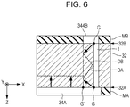
- Fig. 6 is a cross-sectional view for explaining the progression of the etching step.
- Fig. 6 is an enlarged view of a portion VI in Fig. 5B including a portion where the concave portion 34' and the second hole portion 344' are formed.
- etching of the concave portion 34' and etching of the second hole portion 344' simultaneously progress as indicated by arrows in Fig. 6 .
- the preliminary hole forming step for forming the preliminary holes t is performed before the etching step, sagging of the opening of the second hole portion 344' can be suppressed.
- sagging surfaces DA and DB that are inclined are formed in such a manner that the openings widen outward at the edge of the openings of the flow channel.
- the portion where the formation of the sagging surfaces DA and DB starts is formed from the edge G' of the openings of the second hole portion 344' to the edge G of the openings of the preliminary hole t which is inside the opening of the second hole portion 344'.
- the sagging surfaces DA and DB start to be formed from the openings of the preliminary holes t, even if the sagging surfaces DA and DB are formed, the sagging surfaces DA and DB are formed at the edge of the openings of the second hole portion 344', and because the etching in the depth direction of the concave portion 34' advances considerably up until the sagging surfaces DA and DB reach the edge of the openings of the second hole portion 344', sagging of the opening of the second hole portion 344' by etching can be suppressed. Similarly, sagging can be suppressed in the first hole portion 326'and the third hole portion 342'.
- the depth (the length in the plate thickness direction) of the first hole portion 326', the second hole portion 344', and the third hole portion 342' can be formed deep. As a result, the inertance on the supply-side can be stabilized.
- the flow channel including the concave portion 34', the first hole portion 326', the second hole portion 344', and the third hole portion 342' can be formed by one-step etching, it is possible to reduce the number of steps as compared with the case of forming the flow channel with two or more steps of etching. Consequently, the manufacturing cost of the liquid ejecting head 20 can be reduced and the manufacturing time can also be shortened.
- etching of the concave portion in the second step etching of the sagging surface at the edge of the openings of the hole portions formed by etching in the first step is further performed and there is a possibility that the openings of the hole portions become further widened. According to the manufacturing method of this embodiment, it is possible to suppress sagging of the openings of the hole portions by forming the flow channel including the concave portion and the hole portions by one-step etching.
- the etching proceeds through openings of both of the first surface 32A and the second surface 32B through which through holes serving as the preliminary holes t penetrate. Consequently, because etching proceeds in the depth direction from both the first surface 32A and the second surface 32B, the etching time for forming the first hole portion 326', the second hole portion 344', and the third hole portion 342' can be shortened more than the case where etching proceeds from only one surface. Therefore, as the etching time becomes shorter, sagging can be suppressed more than in the case where etching proceeds from only one surface.
- the preliminary hole forming step since a plurality of through holes are formed as the preliminary holes t of the third hole portion 342', etching progresses from a plurality of through holes in the etching process. Therefore, the etching time can be made shorter than in the case where the number of through holes is one.
- Fig. 5B the case where three through holes are formed as the preliminary holes t of the third hole portion 342' is exemplified. Specifically, the preliminary holes t of the third hole portion 342' constitute one through hole at each end portion in the radial direction (X direction) and one through hole at the center portion.
- the through holes as the preliminary holes t before the etching, it is possible to prevent the crystal face (111), which inhibits penetration by etching, from appearing. As a result, the opening width of the hole portions can be reduced. Therefore, the entirety of the liquid ejecting head 20 can be reduced in size.
- the mask layers MA and MB are removed by etching.
- the series of steps of manufacturing the communication substrate 32 is completed.
- FIG. 7 is a plan view of the communication substrate 32 of the liquid ejecting head 20 according to the second embodiment as seen from above (Z direction), and Fig. 8 is a cross-sectional view taken along line VIII-VIII illustrated in Fig. 7 .
- the liquid ejecting head 20 of the second embodiment has a structure (the left side portion in Fig. 8 ) corresponding to the nozzle row L1 and a structure (the right side portion in Fig. 8 ) corresponding to the nozzle row L2 which share the common liquid chamber 34.
- the inflow openings 342 of the common liquid chamber 34 are arranged at the negative-side and positive-side end portions of the common liquid chamber 34 in the Y direction.
- the manufacturing method of the first embodiment can also be applied to the communication substrate 32 of the liquid ejecting head 20 having such a configuration.
- the concave portion forming the common liquid chamber 34, the nozzle-side communication flow channels 326, the supply-side communication flow channels 344, and the inflow openings 342 of the second embodiment can all be formed in the communication substrate 32 by one step of etching and sagging of the opening of the hole portions can also be suppressed.
Landscapes
- Engineering & Computer Science (AREA)
- Manufacturing & Machinery (AREA)
- Physics & Mathematics (AREA)
- Optics & Photonics (AREA)
- Particle Formation And Scattering Control In Inkjet Printers (AREA)
Applications Claiming Priority (1)
| Application Number | Priority Date | Filing Date | Title |
|---|---|---|---|
| JP2016253678A JP2018103515A (ja) | 2016-12-27 | 2016-12-27 | 液体吐出ヘッドの製造方法 |
Publications (1)
| Publication Number | Publication Date |
|---|---|
| EP3351390A1 true EP3351390A1 (de) | 2018-07-25 |
Family
ID=60673175
Family Applications (1)
| Application Number | Title | Priority Date | Filing Date |
|---|---|---|---|
| EP17206704.3A Withdrawn EP3351390A1 (de) | 2016-12-27 | 2017-12-12 | Verfahren zur herstellung eines flüssigkeitsausstosskopfes |
Country Status (4)
| Country | Link |
|---|---|
| US (1) | US20180178518A1 (de) |
| EP (1) | EP3351390A1 (de) |
| JP (1) | JP2018103515A (de) |
| CN (1) | CN108237777A (de) |
Citations (12)
| Publication number | Priority date | Publication date | Assignee | Title |
|---|---|---|---|---|
| US6563079B1 (en) * | 1999-02-25 | 2003-05-13 | Seiko Epson Corporation | Method for machining work by laser beam |
| US20060261034A1 (en) * | 2005-05-23 | 2006-11-23 | Canon Kabushiki Kaisha | Liquid discharge head and producing method therefor |
| US20070019043A1 (en) * | 2005-07-20 | 2007-01-25 | Kazufumi Oya | Liquid-jet head and liquid-jet apparatus, and methods for manufacturing the same |
| JP2007098813A (ja) | 2005-10-05 | 2007-04-19 | Seiko Epson Corp | 液体噴射ヘッドの製造方法 |
| JP2007098812A (ja) * | 2005-10-05 | 2007-04-19 | Seiko Epson Corp | 液体噴射ヘッドの製造方法 |
| US20080043068A1 (en) * | 2006-08-18 | 2008-02-21 | Seiko Epson Corporation | Droplet discharging head, droplet discharging apparatus, method for manufacturing droplet discharging head and method for manufacturing droplet discharging apparatus |
| EP2202076A2 (de) * | 2008-12-19 | 2010-06-30 | Canon Kabushiki Kaisha | Flüssigkeitsausstoßkopf und Verfahren zur Herstellung des Flüssigkeitsausstoßkopfs |
| US20100255616A1 (en) * | 2009-04-01 | 2010-10-07 | Canon Kabushiki Kaisha | Method of manufacturing substrate for liquid discharge head |
| JP2013146885A (ja) * | 2012-01-18 | 2013-08-01 | Seiko Epson Corp | 液体噴射ヘッド、液体噴射装置、液体噴射ヘッドの製造方法 |
| US20140217066A1 (en) * | 2013-02-06 | 2014-08-07 | Seiko Epson Corporation | Silicon substrate processing method, element embedded substrate, and channel forming substrate |
| EP2990207A1 (de) * | 2014-09-01 | 2016-03-02 | Seiko Epson Corporation | Strömungswegkomponente, flüssigkeitsabgabekopf und flüssigkeitsabgabevorrichtung |
| EP3202576A1 (de) * | 2016-01-29 | 2017-08-09 | Seiko Epson Corporation | Flüssigkeitsausstosskopf, flüssigkeitsausstossvorrichtung und verfahren zur herstellung einer flüssigkeitsausstossvorrichtung |
Family Cites Families (6)
| Publication number | Priority date | Publication date | Assignee | Title |
|---|---|---|---|---|
| JP2007045123A (ja) * | 2005-08-12 | 2007-02-22 | Seiko Epson Corp | 液滴吐出ヘッド、液滴吐出装置並びに液滴吐出ヘッドの製造方法 |
| JP2009006536A (ja) * | 2007-06-27 | 2009-01-15 | Seiko Epson Corp | 液滴吐出ヘッド、液滴吐出装置及び液滴吐出ヘッドの製造方法 |
| JP5862116B2 (ja) * | 2011-08-26 | 2016-02-16 | 大日本印刷株式会社 | 液体吐出装置の流路板の製造方法 |
| US8757782B2 (en) * | 2011-11-21 | 2014-06-24 | Seiko Epson Corporation | Liquid ejecting head and liquid ejecting apparatus |
| EP2956306A4 (de) * | 2013-02-13 | 2017-01-11 | Hewlett-Packard Development Company, L.P. | Flüssigkeitsausstossvorrichtung |
| JP2016022582A (ja) * | 2014-07-16 | 2016-02-08 | セイコーエプソン株式会社 | シリコン基板の加工方法および液滴吐出ヘッド |
-
2016
- 2016-12-27 JP JP2016253678A patent/JP2018103515A/ja active Pending
-
2017
- 2017-11-09 CN CN201711099112.7A patent/CN108237777A/zh active Pending
- 2017-12-12 EP EP17206704.3A patent/EP3351390A1/de not_active Withdrawn
- 2017-12-12 US US15/839,557 patent/US20180178518A1/en not_active Abandoned
Patent Citations (12)
| Publication number | Priority date | Publication date | Assignee | Title |
|---|---|---|---|---|
| US6563079B1 (en) * | 1999-02-25 | 2003-05-13 | Seiko Epson Corporation | Method for machining work by laser beam |
| US20060261034A1 (en) * | 2005-05-23 | 2006-11-23 | Canon Kabushiki Kaisha | Liquid discharge head and producing method therefor |
| US20070019043A1 (en) * | 2005-07-20 | 2007-01-25 | Kazufumi Oya | Liquid-jet head and liquid-jet apparatus, and methods for manufacturing the same |
| JP2007098813A (ja) | 2005-10-05 | 2007-04-19 | Seiko Epson Corp | 液体噴射ヘッドの製造方法 |
| JP2007098812A (ja) * | 2005-10-05 | 2007-04-19 | Seiko Epson Corp | 液体噴射ヘッドの製造方法 |
| US20080043068A1 (en) * | 2006-08-18 | 2008-02-21 | Seiko Epson Corporation | Droplet discharging head, droplet discharging apparatus, method for manufacturing droplet discharging head and method for manufacturing droplet discharging apparatus |
| EP2202076A2 (de) * | 2008-12-19 | 2010-06-30 | Canon Kabushiki Kaisha | Flüssigkeitsausstoßkopf und Verfahren zur Herstellung des Flüssigkeitsausstoßkopfs |
| US20100255616A1 (en) * | 2009-04-01 | 2010-10-07 | Canon Kabushiki Kaisha | Method of manufacturing substrate for liquid discharge head |
| JP2013146885A (ja) * | 2012-01-18 | 2013-08-01 | Seiko Epson Corp | 液体噴射ヘッド、液体噴射装置、液体噴射ヘッドの製造方法 |
| US20140217066A1 (en) * | 2013-02-06 | 2014-08-07 | Seiko Epson Corporation | Silicon substrate processing method, element embedded substrate, and channel forming substrate |
| EP2990207A1 (de) * | 2014-09-01 | 2016-03-02 | Seiko Epson Corporation | Strömungswegkomponente, flüssigkeitsabgabekopf und flüssigkeitsabgabevorrichtung |
| EP3202576A1 (de) * | 2016-01-29 | 2017-08-09 | Seiko Epson Corporation | Flüssigkeitsausstosskopf, flüssigkeitsausstossvorrichtung und verfahren zur herstellung einer flüssigkeitsausstossvorrichtung |
Also Published As
| Publication number | Publication date |
|---|---|
| US20180178518A1 (en) | 2018-06-28 |
| CN108237777A (zh) | 2018-07-03 |
| JP2018103515A (ja) | 2018-07-05 |
Similar Documents
| Publication | Publication Date | Title |
|---|---|---|
| JP5336774B2 (ja) | ヘッドチップ、液体噴射ヘッド及び液体噴射装置 | |
| JP2009292061A (ja) | ヘッドチップ、液体噴射ヘッド及び液体噴射装置 | |
| WO2016114396A1 (ja) | インクジェットヘッド及びインクジェット記録装置 | |
| JP2018506455A (ja) | 流体供給孔を有する流体噴射装置 | |
| US9969159B2 (en) | Liquid ejecting head and liquid ejecting apparatus | |
| US8449783B2 (en) | Method of manufacturing liquid ejection head substrate | |
| KR20110047129A (ko) | 액체 분사 헤드, 액체 분사 장치 및 액체 분사 헤드의 제조 방법 | |
| JP6767666B2 (ja) | 液体噴射ヘッド及び液体噴射装置並びに液体噴射装置の製造方法 | |
| CN112297624B (zh) | 液体喷出头以及液体喷出装置 | |
| JP2010158864A (ja) | 液体噴射ヘッドチップ及びその製造方法、並びに液体噴射ヘッド及び液体噴射記録装置 | |
| JP6264902B2 (ja) | 液体噴射ヘッド、および、液体噴射装置 | |
| JP2016049726A (ja) | 流路部品、液体吐出ヘッド、および、液体吐出装置 | |
| US6290341B1 (en) | Ink jet printing head which prevents the stagnation of ink in the vicinity of the nozzle orifices | |
| US10000060B2 (en) | Liquid ejecting head and liquid ejecting apparatus | |
| US9919528B2 (en) | Liquid ejecting head, liquid ejecting apparatus, and liquid ejecting head manufacturing method | |
| JP2010284908A (ja) | インクジェットヘッドおよびその製造方法 | |
| KR100849745B1 (ko) | 액체 토출 소자 및 그 제조 방법 | |
| EP3351390A1 (de) | Verfahren zur herstellung eines flüssigkeitsausstosskopfes | |
| JP2016159441A (ja) | 液体噴射ヘッド、液体噴射装置および液体噴射ヘッドの製造方法 | |
| US9144987B2 (en) | Liquid flow-path member, liquid ejecting head, and liquid ejecting apparatus | |
| US9889657B2 (en) | Liquid ejecting head and liquid ejecting apparatus | |
| JP4274556B2 (ja) | 液体吐出素子の製造方法 | |
| JP7259386B2 (ja) | 液体噴射ヘッドおよび液体噴射装置 | |
| CN115848017B (zh) | 液体喷头 | |
| JP5719523B2 (ja) | 液体噴射記録ヘッド、液体噴射記録装置及び液体噴射ヘッドの製造方法 |
Legal Events
| Date | Code | Title | Description |
|---|---|---|---|
| PUAI | Public reference made under article 153(3) epc to a published international application that has entered the european phase |
Free format text: ORIGINAL CODE: 0009012 |
|
| STAA | Information on the status of an ep patent application or granted ep patent |
Free format text: STATUS: THE APPLICATION HAS BEEN PUBLISHED |
|
| AK | Designated contracting states |
Kind code of ref document: A1 Designated state(s): AL AT BE BG CH CY CZ DE DK EE ES FI FR GB GR HR HU IE IS IT LI LT LU LV MC MK MT NL NO PL PT RO RS SE SI SK SM TR |
|
| AX | Request for extension of the european patent |
Extension state: BA ME |
|
| STAA | Information on the status of an ep patent application or granted ep patent |
Free format text: STATUS: REQUEST FOR EXAMINATION WAS MADE |
|
| 17P | Request for examination filed |
Effective date: 20190110 |
|
| RBV | Designated contracting states (corrected) |
Designated state(s): AL AT BE BG CH CY CZ DE DK EE ES FI FR GB GR HR HU IE IS IT LI LT LU LV MC MK MT NL NO PL PT RO RS SE SI SK SM TR |
|
| STAA | Information on the status of an ep patent application or granted ep patent |
Free format text: STATUS: THE APPLICATION HAS BEEN WITHDRAWN |
|
| 18W | Application withdrawn |
Effective date: 20190814 |