EP3351971B1 - Réseau scintillant - Google Patents
Réseau scintillant Download PDFInfo
- Publication number
- EP3351971B1 EP3351971B1 EP16845968.3A EP16845968A EP3351971B1 EP 3351971 B1 EP3351971 B1 EP 3351971B1 EP 16845968 A EP16845968 A EP 16845968A EP 3351971 B1 EP3351971 B1 EP 3351971B1
- Authority
- EP
- European Patent Office
- Prior art keywords
- scintillator
- film
- neutron
- array according
- scintillator array
- Prior art date
- Legal status (The legal status is an assumption and is not a legal conclusion. Google has not performed a legal analysis and makes no representation as to the accuracy of the status listed.)
- Active
Links
Images


Classifications
-
- G—PHYSICS
- G01—MEASURING; TESTING
- G01T—MEASUREMENT OF NUCLEAR OR X-RADIATION
- G01T1/00—Measuring X-radiation, gamma radiation, corpuscular radiation, or cosmic radiation
- G01T1/16—Measuring radiation intensity
- G01T1/20—Measuring radiation intensity with scintillation detectors
- G01T1/2002—Optical details, e.g. reflecting or diffusing layers
-
- G—PHYSICS
- G01—MEASURING; TESTING
- G01T—MEASUREMENT OF NUCLEAR OR X-RADIATION
- G01T3/00—Measuring neutron radiation
- G01T3/06—Measuring neutron radiation with scintillation detectors
-
- C—CHEMISTRY; METALLURGY
- C09—DYES; PAINTS; POLISHES; NATURAL RESINS; ADHESIVES; COMPOSITIONS NOT OTHERWISE PROVIDED FOR; APPLICATIONS OF MATERIALS NOT OTHERWISE PROVIDED FOR
- C09K—MATERIALS FOR MISCELLANEOUS APPLICATIONS, NOT PROVIDED FOR ELSEWHERE
- C09K11/00—Luminescent materials, e.g. electroluminescent or chemiluminescent
- C09K11/08—Luminescent materials, e.g. electroluminescent or chemiluminescent containing inorganic luminescent materials
- C09K11/77—Luminescent materials, e.g. electroluminescent or chemiluminescent containing inorganic luminescent materials containing rare earth metals
- C09K11/7715—Luminescent materials, e.g. electroluminescent or chemiluminescent containing inorganic luminescent materials containing rare earth metals containing cerium
- C09K11/7727—Sulfates
-
- C—CHEMISTRY; METALLURGY
- C09—DYES; PAINTS; POLISHES; NATURAL RESINS; ADHESIVES; COMPOSITIONS NOT OTHERWISE PROVIDED FOR; APPLICATIONS OF MATERIALS NOT OTHERWISE PROVIDED FOR
- C09K—MATERIALS FOR MISCELLANEOUS APPLICATIONS, NOT PROVIDED FOR ELSEWHERE
- C09K11/00—Luminescent materials, e.g. electroluminescent or chemiluminescent
- C09K11/08—Luminescent materials, e.g. electroluminescent or chemiluminescent containing inorganic luminescent materials
- C09K11/77—Luminescent materials, e.g. electroluminescent or chemiluminescent containing inorganic luminescent materials containing rare earth metals
- C09K11/7766—Luminescent materials, e.g. electroluminescent or chemiluminescent containing inorganic luminescent materials containing rare earth metals containing two or more rare earth metals
- C09K11/7781—Sulfates
-
- G—PHYSICS
- G01—MEASURING; TESTING
- G01T—MEASUREMENT OF NUCLEAR OR X-RADIATION
- G01T1/00—Measuring X-radiation, gamma radiation, corpuscular radiation, or cosmic radiation
- G01T1/16—Measuring radiation intensity
- G01T1/161—Applications in the field of nuclear medicine, e.g. in vivo counting
- G01T1/164—Scintigraphy
- G01T1/1641—Static instruments for imaging the distribution of radioactivity in one or two dimensions using one or several scintillating elements; Radio-isotope cameras
- G01T1/1644—Static instruments for imaging the distribution of radioactivity in one or two dimensions using one or several scintillating elements; Radio-isotope cameras using an array of optically separate scintillation elements permitting direct location of scintillations
-
- G—PHYSICS
- G01—MEASURING; TESTING
- G01T—MEASUREMENT OF NUCLEAR OR X-RADIATION
- G01T1/00—Measuring X-radiation, gamma radiation, corpuscular radiation, or cosmic radiation
- G01T1/16—Measuring radiation intensity
- G01T1/20—Measuring radiation intensity with scintillation detectors
-
- G—PHYSICS
- G01—MEASURING; TESTING
- G01T—MEASUREMENT OF NUCLEAR OR X-RADIATION
- G01T1/00—Measuring X-radiation, gamma radiation, corpuscular radiation, or cosmic radiation
- G01T1/16—Measuring radiation intensity
- G01T1/20—Measuring radiation intensity with scintillation detectors
- G01T1/203—Measuring radiation intensity with scintillation detectors the detector being made of plastics
- G01T1/2033—Selection of materials
Definitions
- Embodiments described herein generally relate to a scintillator array.
- He-3 gas detector using 3He (hereinafter, mentioned as He-3.) gas which is an isotope of He (helium) and having high detection efficiency and a scintillation detector including a scintillator which reacts with neutrons directly or secondarily to emit light.
- He-3 gas detector using 3He (hereinafter, mentioned as He-3.) gas which is an isotope of He (helium) and having high detection efficiency
- a scintillation detector including a scintillator which reacts with neutrons directly or secondarily to emit light.
- a neutron converter which converts neutrons into charged particles, gamma rays, or the like is required for detecting the neutrons.
- the neutron converter there have been known He-3, Li-6, B-10, Cd-113, Gd-155, and Gd-157 having a large neutron absorption cross section, but at present, the He-3 gas detector which is a neutron detector using the He-3 gas is used due to low sensitivity to gamma rays.
- epithermal neutrons also known as epithermal
- the scintillation detector has a high counting capacity. However, density is high and sensitivity to gamma rays is high due to a solid body. In order to detect neutrons at a high counting rate, it is essential to use a neutron detection scintillator having a short fluorescence lifetime. Therefore, for example, a neutron detector using a scintillator constituted of a Li 2 B 4 O 7 single crystal for neutron detection and having a combination of its fluorescent property and a photomultiplier tube is under development.
- a scintillator constituted of light elements is preferable, and because Li, B, and O are the light elements, the scintillator constituted of the Li 2 B 4 O 7 single crystal satisfies a demand also in terms of the above.
- a neutron scintillator which is capable of having a configuration thinner compared with a conventional neutron scintillator and is more excellent in terms of gamma-ray sensitivity and position resolution compared with a conventional Li-based scintillator is under development.
- This is produced by, using a neutron scintillator formed into glass by adding Ce to an oxide constituted of B and Li as main components as a starting raw material, mixing Li 2 B 4 O 7 and CeO 2 , thereafter heating the mixture at temperatures of at least 950°C or higher and holding it for one hour or longer, and thereafter cooling it at a rate of 150°C/sec or more between temperatures of 800 and 400°C.
- LiBO 3 and L 12 B 4 O 7 compounds constituted of only these light elements having low gamma-ray sensitivity light emission by neutrons is very small. Furthermore, in single crystals obtained by adding Ce to these, an amount of Ce solid-dissolving in the crystals is very small, the light emission by neutrons is small, and it is difficult to use them as a two-dimensional detector for neutron imaging or for neutron radiography.
- scintillator materials can be selected regardless of the gamma-ray sensitivity because a several MeV charged particle production reaction is used for the neutron detection.
- B can be expected to have neutron detection efficiency about four times of that of the same amount of Li, it is possible to produce a thinner scintillator. Because this is very advantageous in terms of the gamma-ray sensitivity and the position resolution, an ideal neutron converter is enabled.
- B has about half charged particle energy to be produced of that of commercially available Li glass (Li-Glass) and is considered disadvantageous in terms of light emission output, and in most of the conventional neutron scintillators, Li is used as a converter.
- This neutron scintillator has a high light emission amount and is also excellent in handleability, but is opaque and has limitations to detection efficiency and counting capacity.
- a resolution when high-definition imaging is performed depends on a spread in emitting light by putting a reactant and a scintillator together or a resolution of an optical system or an image sensor which images the light.
- a charge coupled device (CCD) element or a CMOS element used for an imaging system has been increasing dramatically, and therefore a configuration of a reaction film and a scintillator is considered to mainly determine the resolution.
- LiF/ZnS Li reacts with neutrons to emit alpha ( ⁇ ) rays, and the ⁇ rays make a ZnS phosphor emit light.
- An actual configuration, in which LiF/ZnS is granular powder, has a LiF/ZnS powder held by an organic binder on an Al plate which is used as a substrate in many cases.
- an enriched isotope Li-6 is normally used in order to increase reaction efficiency.
- a thickness of a coated layer is about several hundreds ⁇ m. Therefore, the resolution is determined by the thickness of the coated layer and is not high.
- the layer is considered to be made thicker in order to increase the rate of reaction, but because LiF/ZnS is opaque and emitted light scatters in LiF/ZnS and is not transmitted, the efficiency does not increase even though the layer is made thicker.
- a neutron detector is constituted of a capillary plate having a plurality of openings passing through in a thickness direction and filled with a liquid scintillator which reacts with neutrons in a plurality of these openings and an imaging detector, and which measures scintillation light.
- a neutron detector is constituted of a capillary plate having a plurality of openings passing through in a thickness direction and filled with a liquid scintillator which reacts with neutrons in a plurality of these openings and an imaging detector, and which measures scintillation light.
- an imaging intensifier which combines a reaction film and a scintillator, converts light from the scintillator into electrons by using a photoelectric conversion film, and amplifies the electrons is also under development in order to achieve high definition and increase sensitivity.
- a thickness of the reaction film is about 5 ⁇ m for the purpose of high definition, and in a case of B-10, reaction efficiency with neutrons is about 10%, and remaining 90% of the neutrons is transmitted and is not used.
- energy of neutrons increases, the reaction efficiency decreases further. Therefore, the reaction efficiency is poor despite high definition, and when the number of generated neutrons is small (flux is small), integration is to be performed by spending time.
- JP H04-290985 A KR 2011-0115432 A , and JP 2012-225680 A relate to prior art scintillators.
- a scintillator array to be used for a neutron detector capable of detecting high energy neutrons with high definition and high efficiency.
- the invention is defined by claim 1.
- Patent Reference 1 Re-publication of PCT International Publication No. WO 2008/132849 A1
- FIG. 1 is a view illustrating a structure example of a scintillator array to be used for a neutron detector according to one embodiment of the present invention. Further, FIG. 5 and FIG. 6 are views illustrating structure examples of scintillator arrays to be used for conventional neutron detectors.
- the scintillator array to be used for the conventional neutron detector illustrated in FIG. 5 has granular scintillators 4 (for example, LiF/ZnS phosphors).
- the granular scintillators 4 are provided with an aluminum substrate 17 composed of aluminum (a material which easily transmits neutrons) and a transparent binder 6 provided for efficiently transmitting an emitted light 5 while fixing the granular scintillators 4 which become a structure.
- the granular scintillators 4 are fixed on the aluminum substrate 17 with the binder 6 to constitute the scintillator array to be used for the neutron detector.
- a basic mechanism of neutron detection is as follows.
- a neutron (n) 1 is transmitted through the aluminum substrate 17 and reacts with Li of the granular scintillators 4.
- Li is an isotope of Li-6, and this Li-6 and the neutron (n) 1 react with each other to emit alpha ( ⁇ ) rays 2.
- This reaction is mentioned as (n, ⁇ ).
- the emitted ⁇ rays 2 make a ZnS phosphor of the granular scintillators 4 emit the light 5.
- the ⁇ rays 2 are emitted in all directions in the granular scintillators 4 and have a range (a flying distance of radiation rays) of a degree of about 5 ⁇ m to 10 ⁇ m.
- a value of a particle size of the granular scintillators 4 is substantially the same as a value of the range of these ⁇ rays 2, and the light 5 emitted inside the granular scintillators 4 is absorbed and attenuated in the granular scintillators 4 and comes out of the granular scintillators 4 at the same time.
- This light 5 is transmitted in other granular scintillators 4 and reflects on the granular scintillators 4, and further is transmitted in the binder 6 and comes out of the neutron detector.
- LiF/ZnS which is a ratio of LiF to ZnS
- LiF/ZnS is 1/4, and when the number of atoms of the binder 6 is taken into consideration, the whole reaction efficiency becomes poor.
- Scintillators which are used for imaging actually and have this configuration have a thickness of about several hundreds ⁇ m.
- a reaction cross section with Li-6 is several digits smaller than a reaction cross section with Li-6 in a thermal neutron. Therefore, because the thickness is to be increased further in order to increase the reaction efficiency, the resolution becomes poorer and poorer.
- a method illustrated in FIG. 6 is practically used.
- B-10 a thermal neutron cross section: 3838 barns
- Li-6 a thermal neutron cross section: 940 barns
- a proportion of the number of atoms to react is also 4/5 in a film 7.
- the film 7 is formed by vapor deposition without using a binder, a proportion of B-10 existing in unit volume is also large, which allows the efficiency to be increased even though a thickness is small.
- a range of the ⁇ rays 2 emitted by a (n, ⁇ ) reaction is a degree of about 4 to 5 ⁇ m, and therefore when the thickness is more than 5 ⁇ m, the ⁇ rays 2 emitted on an incident side by a reaction with a neutron 1 cannot pass through the film 7 and reach a CsI phosphor 8.
- the thickness of the film 7 is 5 ⁇ m, looking overall, about 80% of thermal neutrons is transmitted and only a degree of about 20% of the thermal neutrons is effectively utilized.
- an atom density per unit volume in a reaction surface is higher compared with a case of the configuration in FIG. 5 , and the reaction film of about 5 ⁇ m allows high-definition imaging.
- the needle-shaped CsI phosphor 8 having high transparency sheds the light 5 in accordance with the ⁇ rays 2, and the photoelectric conversion film 18 generates an electron 10 in accordance with the light 5.
- Amplification of this electron increases efficiency of conversion and transmission and makes it possible to obtain sensitivity about 100 or more times compared with a case of photographing by using an image sensor as the configuration illustrated in FIG. 5 .
- FIG. 8 having a vertical axis representing a neutron absorption cross section and a horizontal axis representing neutron energy, in a case of a high energy neutron (fast neutron), the neutron absorption cross section is two digits smaller compared with that of a thermal neutron, and therefore a rate of reaction is extremely low.
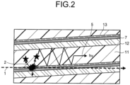
- FIGs. 1 and 2 a configuration of a scintillator array to be used for a neutron detector according to one embodiment of the present invention will be described referring to FIGs. 1 and 2 .
- FIGs. 1 and 2 are views illustrating a structure example of a detection part of the scintillator array to be used for the neutron detector according to an embodiment of the present invention.
- the scintillator array illustrated in FIG. 1 is provided with a substrate 3 which is a ceramic substrate composed of white ceramics such as AlN (aluminum nitride) or a silicon single crystal substrate so as to be located on an incident side of a neutron 1. Adjacently to this substrate 3, a multi-layered structure in which each layer extends along an incident direction of the neutron 1 is constituted.
- This multi-layered structure has a multi-layered structure having stacks in which a layered structure constituted of a film 12 which is a ceramic film composed of the white ceramics such as AlN (aluminum nitride) or a silicon single-crystal film, the film 7 which is 10 B 4 C (enriched boron carbide obtained by enriching a boron-10 isotope) vapor-deposition film, a film 13 which is a ceramic vapor-deposition film composed of the white ceramics such as AlN (aluminum nitride) or an Al (aluminum) vapor-deposition film, and a scintillator 11 is layered repeatedly in multistage (for example, several hundreds to several thousands stages) in a first embodiment.
- a layered structure constituted of a film 12 which is a ceramic film composed of the white ceramics such as AlN (aluminum nitride) or a silicon single-crystal film
- the film 7 which is 10 B 4 C (enriched
- This multi-layered structure is alternately arranged in a double-cross shape (grid shape) so that a difference in lamination direction becomes 90 degrees when it is seen from an incident surface side of the neutron 1, and thus the detection part (two-dimensional neutron reaction scintillator) of the scintillator array which has a two-dimensionally expanding neutron incident surface and is used for the neutron detector is constituted.
- the film 12 has a thickness (a length in an upper and lower direction in FIGs. 1 and 2 ) of 5 ⁇ m or more.
- the film 12 extends along the incident direction of the neutron 1.
- the film 12 acts as a reflector which reflects light.
- the film 7 is formed on the film 12 by the vapor deposition and extends along the incident direction of the neutron 1.
- the film 7 has a thickness (a length in the upper and lower direction in FIGs. 1 and 2 ) of about 4 to 5 ⁇ m, for example.
- boron-10 reacts with the neutron 1 to emit radiation rays ( ⁇ rays 2).
- the neutron is incident on the film 7 along a direction intersecting the lamination direction of the layered structure, for example.
- the film 13 has a thickness (a length in the upper and lower direction in FIGs. 1 and 2 ) of about 0.1 ⁇ m to 0.5 ⁇ m.
- the film 13 is formed on the film 7 by the vapor deposition so as to be adjacent to the film 7. Accordingly, the film 13 also extends along the incident direction of the neutron 1.
- the film 13 acts as a reflector which reflects light.
- the scintillator 11 is composed of a plastic scintillator or the like.
- the scintillator 11 is arranged adjacently to the film 13 so as to extend along the incident direction of the neutron 1.
- This scintillator 11 has a thickness (a length in the upper and lower direction in FIGs. 1 and 2 ) of 5 ⁇ m or more.
- the thickness of the scintillator 11 is about several tens ⁇ m to hundreds ⁇ m, for example.
- the scintillator 11 emits the light 5 by the ⁇ rays 2 emitted in the film 7.
- the scintillator 11 also includes either type of a rare earth oxysulfide phosphor or garnet, and further includes at least one selected from praseodymium, terbium, europium, cerium, zirconium, and phosphorus as an activator in these.
- a scintillator layer includes a material represented by a general formula Y 3 Al 5 O 12 :Ce, a general formula Gd 3 (Al, Ga) 5 O 12 :Ce, a general formula Lu 3 (Al, Ga) 5 O 12 :Ce, a general formula Gd 3 (Al, Ga) 5 O 12 :Tb, a general formula Lu 3 (Al, Ga) 5 O 12 :Tb, or a general formula (Gd, Lu) 3 (Al, Ga) 5 O 12 :Ce.
- the respective layers such as the film 7 are each formed to have an inclination in the lamination direction with respect to the incident direction of the neutron 1, namely, formed to extend along a direction inclined with respect to a direction perpendicular to the substrate 3 and make a rear end side (a right side in the figures) rise toward an upper side in FIGs. 1 and 2 .
- the scintillator array to be used for the neutron detector of this embodiment has the scintillator array 11 sandwiched between the film 13 and the film 12. Further, the film 7 is also formed to be sandwiched by either of the film 13 and the film 12.
- the film 7 is black and has low reflectance of light, and therefore when the film 7 and the scintillator 11 are layered directly, the light 5 emitted in the scintillator 11 cannot be efficiently transmitted.
- making a sandwich structure in which the scintillator 11 is sandwiched by the film 13 and the film 12 as described in this embodiment makes it possible to efficiently transmit the light 5 emitted in the scintillator 11 by using reflection by the film 13 and the film 12 and take out the light 5 to the outside.
- ⁇ rays 2 emitted by the (n, ⁇ ) reaction at each point in the film 7 a component emitted in a direction (a 4 to 5 ⁇ m thickness direction) nearly perpendicular to the neutron 1 is emitted as the light 5 in the scintillator 11.
- the light 5 can be propagated while being reflected by the film 13 and the film 12 in the scintillator 11 having a high transparency, led to the outside of the multi-layered structure, and taken out.
- the film 12 with a thickness of 5 ⁇ m or more absorbs the ⁇ rays 2 coming out downward in the film 7 in FIGs. 1 and 2 and hinders light emission in the scintillator 11 on a lower side. This makes position resolution improve.
- the film 7 is formed so as to extend along the incident direction of the neutron 1 as described above. Then, because the neutron 1 goes not perpendicularly to but nearly horizontally to this film 7, and so as to move on a diagonal line in the inclined arranged film 7, the reaction efficiency can be greatly improved.
- the scintillator array to be used for the neutron detector according to this embodiment makes it possible to greatly improve use efficiency of neutrons and perform propagation of the emitted light 5 with efficiency and without diffusing the light. This makes it possible to obtain the scintillator array to be used for a two-dimensional detector with respect to neutrons which is capable of imaging efficiently with high definition.
- FIG. 7 is a chart illustrating a relationship between a thickness of a reaction material and a transmittance of thermal neutrons.
- a vertical axis represents the transmittance and a horizontal axis represents the thickness.
- a transmittance is about 10%. It is found from this that about 90% of thermal neutrons reacts. Accordingly, setting a length (a length in a left and right direction in FIGs. 1 and 2 ) of the film 7 to about 50 ⁇ m allows the reaction with about 90% of thermal neutrons.
- the scintillator array of the embodiment is capable of high-definition and high-efficiency detection with respect to a wide range of energy of neutrons, particularly with respect to high energy thereof.
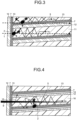
- the scintillator array to be used for the neutron detector of this second embodiment includes a film 12 having a thickness of 5 ⁇ m or more, the film 7, and a film 13 for light reflection having a thickness of about 0.1 ⁇ m to 0.5 ⁇ m so as to extend along a neutron incident surface on a neutron incident side (a left side in FIG. 3 ).
- the films 12 and 13 function as reflective layers, and the film 7 functions as a neutron reaction layer which reacts with neutrons to emit radiation rays. Note that because other parts are constituted similarly to those in the first embodiment illustrated in FIGs. 1 and 2 , the corresponding parts are denoted by the same reference signs and redundant descriptions are omitted.
- the scintillator array to be used for the neutron detector of the second embodiment makes it possible to increase the reaction efficiency with a neutron 1 in a neutron input surface in addition to actions and effects in the neutron detector of the first embodiment. This makes it possible to make a size in a direction (a left and right direction in FIG. 3 ) in which neutrons in the neutron detector are transmitted short and compact.
- the scintillator array to be used for the neutron detector of the third embodiment includes a film 7, a film 12 having a thickness (a length in an upper and lower direction in FIG. 4 ) of 5 ⁇ m or more, and a film 14 (a thickness of 5 ⁇ m or more) for absorbing thermal neutrons which is arranged between the film 7 and the film 12, and a scintillator 16 in place of the scintillator 11.
- the scintillator 16 for example, a plastic scintillator can be used. Further, when a glass scintillator, a polycrystalline scintillator, or a ceramic scintillator of a rare earth oxysulfide phosphor, garnet, or the like, which does not include hydrogen, is used as the scintillator 16, the scintillator is preferably covered with a resin including hydrogen.
- the scintillator array includes the film 12 having the thickness of 5 ⁇ m or more, the film 7, and a film 13 having a thickness of about 0.1 ⁇ m to 0.5 ⁇ m so as to extend along an incident surface of a neutron 1 on an incident side (a left side in FIG. 4 ) of the neutron 1. Note that because other parts are constituted similarly to those in the first embodiment illustrated in FIGs. 1 and 2 , the corresponding parts are denoted by the same reference signs and redundant descriptions are omitted.
- a fast neutron 9 which is a neutron having a high energy component reacts in the film 7 to emit ⁇ rays 2, and these ⁇ rays 2 react in the scintillator 16 to be emitted as a light 5.
- an absorption cross section declines in the order of digits as indicated by a line of a neutron absorption cross section of enriched boron illustrated in FIG. 8 having a vertical axis representing a neutron absorption cross section and a horizontal axis representing neutron energy.
- the scintillator 16 is used and the fast neutron 9 is slowed down by hydrogen.
- Slowed-down neutrons 15 diffuse in an isotropic manner from the scintillator 16.
- the slowed-down neutrons 15 react in the film 7 on a lower side of the scintillator 16, the ⁇ rays 2 are emitted, and these ⁇ rays 2 react with the scintillator 16 to emit the light 5.
- the film 14 which is a Gd 2 O 3 vapor-deposition film including gadolinium (Gd) having a large absorption cross section in a thermal neutron region under the film 7 on the upper side.
- the fast neutron 9 is converted into the slowed-down neutrons 15 by hydrogen atoms of the scintillator 16 and made to react with the film 7. Since the slowed-down neutrons 15 have a range of several centimeters or more and diffuse, the diffusing slowed-down neutrons 15 are absorbed by forming the film 14 (a thickness of about 5 ⁇ m to several tens ⁇ m) on one side (a lower side in FIG. 4 ) of the film 7. This makes it possible to improve the resolution of the detector while increasing the detection efficiency.
Landscapes
- Chemical & Material Sciences (AREA)
- Health & Medical Sciences (AREA)
- Physics & Mathematics (AREA)
- Life Sciences & Earth Sciences (AREA)
- General Physics & Mathematics (AREA)
- High Energy & Nuclear Physics (AREA)
- Molecular Biology (AREA)
- Spectroscopy & Molecular Physics (AREA)
- Engineering & Computer Science (AREA)
- Inorganic Chemistry (AREA)
- Materials Engineering (AREA)
- Organic Chemistry (AREA)
- Biomedical Technology (AREA)
- General Health & Medical Sciences (AREA)
- Medical Informatics (AREA)
- Nuclear Medicine, Radiotherapy & Molecular Imaging (AREA)
- Optics & Photonics (AREA)
- Measurement Of Radiation (AREA)
- Conversion Of X-Rays Into Visible Images (AREA)
Claims (12)
- Réseau scintillant comprenant :une structure incluant une pluralité de piles superposées,dans lequel chaque pile présente dans l'ordre :un réflecteur de lumière (12) incluant des céramiques ou du silicium monocristallin ;un premier film (7) constitué de carbure de bore enrichi incluant un isotope de bore 10 enrichi et configuré pour réagir avec un neutron incident le long d'une direction coupant une direction de stratification des piles et pour émettre ainsi un rayon de radiation ;un deuxième film (13) constitué d'une céramique blanche et configuré pour réfléchir la lumière ; etun scintillateur (11) configuré pour émettre de la lumière (5) en réponse au rayon de radiation.
- Réseau scintillant selon la revendication 1, dans lequel les céramiques incluent un nitrure d'aluminium.
- Réseau scintillant selon la revendication 1, dans lequel les piles sont agencées de telle sorte que les piles présentent une différence de 90 degrés dans la direction de stratification du réflecteur de lumière (12), du premier film (7), du second film (13) et du scintillateur (11).
- Réseau scintillant selon la revendication 1, dans lequel le scintillateur (11) inclut un phosphore oxysulfure de terres rares ou un grenat.
- Réseau scintillant selon la revendication 4, dans lequel le scintillateur (11) inclut en outre au moins un élément sélectionné parmi le praséodyme, le terbium, l'europium, le cérium, le zirconium et le phosphore.
- Réseau scintillant selon la revendication 1, dans lequel le scintillateur (11) inclut un matériau représenté par une formule Y3Al5O12:Ce, une formule Gd3(Al, Ga)5O12:Ce, une formule Lu3(Al, Ga)5O12:Ce, une formule Gd3(Al, Ga)5O12:Tb, une formule Lu3(Al, Ga)5O12:Tb, ou une formule (Gd, Lu)3(Al, Ga)5O12:Ce.
- Réseau scintillant selon la revendication 1, comprenant en outre :une première couche de réflexion de lumière (13) présentant une première surface s'étendant le long d'une surface latérale de la structure ;une deuxième couche de réflexion de lumière (12) présentant une deuxième surface s'étendant le long d'une surface latérale de la structure ; etune couche de réaction neutronique (7) prévue entre les première et deuxième couches de réflexion de la lumière (13, 12) et configurée pour réagir avec un neutron incident et émettre ainsi un rayon de radiation.
- Réseau scintillant selon la revendication 7, dans lequel le réflecteur de lumière (12), le premier film (7), le deuxième film (13) et le scintillateur (11) s'étendent chacun le long d'une direction inclinée par rapport à une direction perpendiculaire à la première surface.
- Réseau scintillant selon la revendication 1,
dans lequel la céramique blanche est constituée de nitrure d'aluminium. - Réseau scintillant selon la revendication 1, dans lequel chacune des piles présente en outre un troisième film (14) configuré pour absorber un neutron thermique, le troisième film (14) étant agencé entre le réflecteur de lumière (12) et le premier film (7).
- Réseau scintillant selon la revendication 10, dans lequel le troisième film inclut un oxyde de gadolinium.
- Réseau scintillant selon la revendication 1, dans lequel le scintillateur (11) est un scintillateur plastique incluant des atomes d'hydrogène, ou un scintillateur incluant un scintillateur en verre ou un scintillateur polycristallin, ou un scintillateur en céramique incluant un phosphore oxysulfure de terres rares ou un grenat, qui est enserré par une couche de résine incluant des atomes d'hydrogène et la couche de résine.
Applications Claiming Priority (2)
| Application Number | Priority Date | Filing Date | Title |
|---|---|---|---|
| JP2015185490 | 2015-09-18 | ||
| PCT/JP2016/004247 WO2017047094A1 (fr) | 2015-09-18 | 2016-09-16 | Réseau scintillant |
Publications (3)
| Publication Number | Publication Date |
|---|---|
| EP3351971A1 EP3351971A1 (fr) | 2018-07-25 |
| EP3351971A4 EP3351971A4 (fr) | 2019-04-03 |
| EP3351971B1 true EP3351971B1 (fr) | 2024-05-08 |
Family
ID=58288611
Family Applications (1)
| Application Number | Title | Priority Date | Filing Date |
|---|---|---|---|
| EP16845968.3A Active EP3351971B1 (fr) | 2015-09-18 | 2016-09-16 | Réseau scintillant |
Country Status (4)
| Country | Link |
|---|---|
| US (1) | US20180196146A1 (fr) |
| EP (1) | EP3351971B1 (fr) |
| JP (1) | JP6762949B2 (fr) |
| WO (1) | WO2017047094A1 (fr) |
Families Citing this family (9)
| Publication number | Priority date | Publication date | Assignee | Title |
|---|---|---|---|---|
| CN107195353B (zh) * | 2017-04-27 | 2019-07-02 | 兰州大学 | 冷热中子敏感的荧光粉在微米级结构上的填充方法 |
| CN108863340B (zh) * | 2017-05-16 | 2020-10-23 | 中国科学院上海硅酸盐研究所 | 一种复合结构透明闪烁陶瓷及其制备方法 |
| CN109020532A (zh) * | 2018-09-28 | 2018-12-18 | 成都东骏激光股份有限公司 | 一种绿色荧光复相陶瓷及其制备方法与应用 |
| PL3908856T3 (pl) | 2019-01-08 | 2025-09-08 | The Research Foundation For The State University Of New York | Światłowód pryzmatoidowy |
| CN110376633A (zh) * | 2019-07-19 | 2019-10-25 | 东软医疗系统股份有限公司 | 医疗探测器及医疗成像设备 |
| US11175417B1 (en) * | 2019-09-30 | 2021-11-16 | National Technology & Engineering Solutions Of Sandia, Llc | Mutli-layered neutron detector |
| CN111863849B (zh) * | 2020-07-29 | 2022-07-01 | 上海大学 | 一种x射线平板探测器及其制备方法 |
| CN113253332B (zh) * | 2021-04-02 | 2024-03-26 | 散裂中子源科学中心 | 一种基于GOS:Tb透明陶瓷闪烁屏的高分辨中子成像探测器及其制造方法 |
| CN113176604A (zh) * | 2021-04-30 | 2021-07-27 | 中国电子科技集团公司第二十六研究所 | 一种闪烁晶体阵列抗辐照加固结构及抗辐照加固方法 |
Family Cites Families (8)
| Publication number | Priority date | Publication date | Assignee | Title |
|---|---|---|---|---|
| JPS5547852A (en) * | 1978-10-04 | 1980-04-05 | Kao Corp | Tampon |
| JPH04290985A (ja) * | 1991-03-19 | 1992-10-15 | Toshiba Corp | 中性子検出器 |
| US6384417B1 (en) * | 1998-09-30 | 2002-05-07 | Kabushiki Kaisha Toshiba | Ceramic scintillator, method for producing same, and x-ray detector and x-ray CT imaging equipment using same |
| US7675039B2 (en) * | 2002-09-26 | 2010-03-09 | Kabushiki Kaisha Toshiba | Phosphor sheet for radiation detector, radiation detector and apparatus for radiographic equipment |
| KR101198067B1 (ko) * | 2010-04-15 | 2012-11-07 | 한국전기연구원 | 수직 적층형 섬광체 구조물을 이용한 방사선 검출 장치 |
| JP5710352B2 (ja) * | 2011-04-15 | 2015-04-30 | 株式会社東芝 | 中性子検出器 |
| EP3489328A1 (fr) * | 2012-11-14 | 2019-05-29 | Koninklijke Philips N.V. | Matériau de scintillateur |
| EP2924691B1 (fr) * | 2012-11-26 | 2019-10-09 | Toray Industries, Inc. | Panneau de scintillateur et son procédé de production |
-
2016
- 2016-09-16 EP EP16845968.3A patent/EP3351971B1/fr active Active
- 2016-09-16 JP JP2017540515A patent/JP6762949B2/ja active Active
- 2016-09-16 WO PCT/JP2016/004247 patent/WO2017047094A1/fr not_active Ceased
-
2018
- 2018-02-28 US US15/907,594 patent/US20180196146A1/en not_active Abandoned
Also Published As
| Publication number | Publication date |
|---|---|
| EP3351971A1 (fr) | 2018-07-25 |
| EP3351971A4 (fr) | 2019-04-03 |
| US20180196146A1 (en) | 2018-07-12 |
| WO2017047094A1 (fr) | 2017-03-23 |
| JP6762949B2 (ja) | 2020-09-30 |
| JPWO2017047094A1 (ja) | 2018-07-26 |
Similar Documents
| Publication | Publication Date | Title |
|---|---|---|
| EP3351971B1 (fr) | Réseau scintillant | |
| McGregor | Materials for gamma-ray spectrometers: Inorganic scintillators | |
| Yanagida | Inorganic scintillating materials and scintillation detectors | |
| US7582880B2 (en) | Neutron detector using lithiated glass-scintillating particle composite | |
| US9182508B2 (en) | Neutron detector using neutron absorbing scintillating particulates in plastic | |
| JP5710352B2 (ja) | 中性子検出器 | |
| CN1892252A (zh) | 伽马和中子辐射检测器 | |
| US8399849B1 (en) | Fast neutron detector | |
| EP3441793B1 (fr) | Réseau de scintillateurs | |
| Komendo et al. | New scintillator 6Li2CaSiO4: Eu2+ for neutron sensitive screens | |
| US20230115203A1 (en) | Crystal-coated bnnt scintillators | |
| CN114236599A (zh) | 中子探测器及中子探测方法 | |
| JP6456946B2 (ja) | 結像システムへの適用のためのCe3+活性化発光組成物 | |
| US10422888B1 (en) | Scintillation detectors | |
| Batra | Advanced Nuclear Radiation Detectors: Materials, Processing, Properties and Applications | |
| Koroleva et al. | New scintillation materials and scintiblocs for neutron and γ-rays registration | |
| US11231507B2 (en) | Radiation monitor | |
| Kuroda et al. | Poissonian-type new radiation imager | |
| JP7117213B2 (ja) | 放射線モニタ及び放射線の測定方法 | |
| JP7691912B2 (ja) | 放射線モニタ、および放射線の検出方法 | |
| Sarkar et al. | Neutron optics and detectors | |
| RU54438U1 (ru) | Преобразователь ионизирующего излучения | |
| Paschotta | Scintillator Materials | |
| Van Eijk et al. | Recent Developments in the Inorganic Scintillator Field | |
| JP2022129614A (ja) | シンチレータおよび放射線測定装置 |
Legal Events
| Date | Code | Title | Description |
|---|---|---|---|
| STAA | Information on the status of an ep patent application or granted ep patent |
Free format text: STATUS: THE INTERNATIONAL PUBLICATION HAS BEEN MADE |
|
| PUAI | Public reference made under article 153(3) epc to a published international application that has entered the european phase |
Free format text: ORIGINAL CODE: 0009012 |
|
| STAA | Information on the status of an ep patent application or granted ep patent |
Free format text: STATUS: REQUEST FOR EXAMINATION WAS MADE |
|
| 17P | Request for examination filed |
Effective date: 20180301 |
|
| AK | Designated contracting states |
Kind code of ref document: A1 Designated state(s): AL AT BE BG CH CY CZ DE DK EE ES FI FR GB GR HR HU IE IS IT LI LT LU LV MC MK MT NL NO PL PT RO RS SE SI SK SM TR |
|
| AX | Request for extension of the european patent |
Extension state: BA ME |
|
| DAV | Request for validation of the european patent (deleted) | ||
| DAX | Request for extension of the european patent (deleted) | ||
| A4 | Supplementary search report drawn up and despatched |
Effective date: 20190304 |
|
| RIC1 | Information provided on ipc code assigned before grant |
Ipc: G01T 1/20 20060101ALI20190226BHEP Ipc: G01T 3/06 20060101AFI20190226BHEP Ipc: C09K 11/77 20060101ALI20190226BHEP |
|
| STAA | Information on the status of an ep patent application or granted ep patent |
Free format text: STATUS: EXAMINATION IS IN PROGRESS |
|
| 17Q | First examination report despatched |
Effective date: 20200714 |
|
| GRAP | Despatch of communication of intention to grant a patent |
Free format text: ORIGINAL CODE: EPIDOSNIGR1 |
|
| STAA | Information on the status of an ep patent application or granted ep patent |
Free format text: STATUS: GRANT OF PATENT IS INTENDED |
|
| INTG | Intention to grant announced |
Effective date: 20231204 |
|
| GRAS | Grant fee paid |
Free format text: ORIGINAL CODE: EPIDOSNIGR3 |
|
| GRAA | (expected) grant |
Free format text: ORIGINAL CODE: 0009210 |
|
| STAA | Information on the status of an ep patent application or granted ep patent |
Free format text: STATUS: THE PATENT HAS BEEN GRANTED |
|
| AK | Designated contracting states |
Kind code of ref document: B1 Designated state(s): AL AT BE BG CH CY CZ DE DK EE ES FI FR GB GR HR HU IE IS IT LI LT LU LV MC MK MT NL NO PL PT RO RS SE SI SK SM TR |
|
| REG | Reference to a national code |
Ref country code: GB Ref legal event code: FG4D |
|
| REG | Reference to a national code |
Ref country code: CH Ref legal event code: EP |
|
| REG | Reference to a national code |
Ref country code: DE Ref legal event code: R096 Ref document number: 602016087454 Country of ref document: DE |
|
| REG | Reference to a national code |
Ref country code: IE Ref legal event code: FG4D |
|
| REG | Reference to a national code |
Ref country code: LT Ref legal event code: MG9D |
|
| REG | Reference to a national code |
Ref country code: NL Ref legal event code: MP Effective date: 20240508 |
|
| PG25 | Lapsed in a contracting state [announced via postgrant information from national office to epo] |
Ref country code: IS Free format text: LAPSE BECAUSE OF FAILURE TO SUBMIT A TRANSLATION OF THE DESCRIPTION OR TO PAY THE FEE WITHIN THE PRESCRIBED TIME-LIMIT Effective date: 20240908 |
|
| PG25 | Lapsed in a contracting state [announced via postgrant information from national office to epo] |
Ref country code: BG Free format text: LAPSE BECAUSE OF FAILURE TO SUBMIT A TRANSLATION OF THE DESCRIPTION OR TO PAY THE FEE WITHIN THE PRESCRIBED TIME-LIMIT Effective date: 20240508 |
|
| PG25 | Lapsed in a contracting state [announced via postgrant information from national office to epo] |
Ref country code: FI Free format text: LAPSE BECAUSE OF FAILURE TO SUBMIT A TRANSLATION OF THE DESCRIPTION OR TO PAY THE FEE WITHIN THE PRESCRIBED TIME-LIMIT Effective date: 20240508 Ref country code: HR Free format text: LAPSE BECAUSE OF FAILURE TO SUBMIT A TRANSLATION OF THE DESCRIPTION OR TO PAY THE FEE WITHIN THE PRESCRIBED TIME-LIMIT Effective date: 20240508 |
|
| PG25 | Lapsed in a contracting state [announced via postgrant information from national office to epo] |
Ref country code: GR Free format text: LAPSE BECAUSE OF FAILURE TO SUBMIT A TRANSLATION OF THE DESCRIPTION OR TO PAY THE FEE WITHIN THE PRESCRIBED TIME-LIMIT Effective date: 20240809 |
|
| PG25 | Lapsed in a contracting state [announced via postgrant information from national office to epo] |
Ref country code: PT Free format text: LAPSE BECAUSE OF FAILURE TO SUBMIT A TRANSLATION OF THE DESCRIPTION OR TO PAY THE FEE WITHIN THE PRESCRIBED TIME-LIMIT Effective date: 20240909 |
|
| REG | Reference to a national code |
Ref country code: AT Ref legal event code: MK05 Ref document number: 1685447 Country of ref document: AT Kind code of ref document: T Effective date: 20240508 |
|
| PG25 | Lapsed in a contracting state [announced via postgrant information from national office to epo] |
Ref country code: NL Free format text: LAPSE BECAUSE OF FAILURE TO SUBMIT A TRANSLATION OF THE DESCRIPTION OR TO PAY THE FEE WITHIN THE PRESCRIBED TIME-LIMIT Effective date: 20240508 |
|
| PG25 | Lapsed in a contracting state [announced via postgrant information from national office to epo] |
Ref country code: ES Free format text: LAPSE BECAUSE OF FAILURE TO SUBMIT A TRANSLATION OF THE DESCRIPTION OR TO PAY THE FEE WITHIN THE PRESCRIBED TIME-LIMIT Effective date: 20240508 |
|
| PG25 | Lapsed in a contracting state [announced via postgrant information from national office to epo] |
Ref country code: AT Free format text: LAPSE BECAUSE OF FAILURE TO SUBMIT A TRANSLATION OF THE DESCRIPTION OR TO PAY THE FEE WITHIN THE PRESCRIBED TIME-LIMIT Effective date: 20240508 |
|
| PG25 | Lapsed in a contracting state [announced via postgrant information from national office to epo] |
Ref country code: PL Free format text: LAPSE BECAUSE OF FAILURE TO SUBMIT A TRANSLATION OF THE DESCRIPTION OR TO PAY THE FEE WITHIN THE PRESCRIBED TIME-LIMIT Effective date: 20240508 |
|
| PG25 | Lapsed in a contracting state [announced via postgrant information from national office to epo] |
Ref country code: LV Free format text: LAPSE BECAUSE OF FAILURE TO SUBMIT A TRANSLATION OF THE DESCRIPTION OR TO PAY THE FEE WITHIN THE PRESCRIBED TIME-LIMIT Effective date: 20240508 |
|
| PG25 | Lapsed in a contracting state [announced via postgrant information from national office to epo] |
Ref country code: PT Free format text: LAPSE BECAUSE OF FAILURE TO SUBMIT A TRANSLATION OF THE DESCRIPTION OR TO PAY THE FEE WITHIN THE PRESCRIBED TIME-LIMIT Effective date: 20240909 Ref country code: PL Free format text: LAPSE BECAUSE OF FAILURE TO SUBMIT A TRANSLATION OF THE DESCRIPTION OR TO PAY THE FEE WITHIN THE PRESCRIBED TIME-LIMIT Effective date: 20240508 Ref country code: NO Free format text: LAPSE BECAUSE OF FAILURE TO SUBMIT A TRANSLATION OF THE DESCRIPTION OR TO PAY THE FEE WITHIN THE PRESCRIBED TIME-LIMIT Effective date: 20240808 Ref country code: NL Free format text: LAPSE BECAUSE OF FAILURE TO SUBMIT A TRANSLATION OF THE DESCRIPTION OR TO PAY THE FEE WITHIN THE PRESCRIBED TIME-LIMIT Effective date: 20240508 Ref country code: LV Free format text: LAPSE BECAUSE OF FAILURE TO SUBMIT A TRANSLATION OF THE DESCRIPTION OR TO PAY THE FEE WITHIN THE PRESCRIBED TIME-LIMIT Effective date: 20240508 Ref country code: IS Free format text: LAPSE BECAUSE OF FAILURE TO SUBMIT A TRANSLATION OF THE DESCRIPTION OR TO PAY THE FEE WITHIN THE PRESCRIBED TIME-LIMIT Effective date: 20240908 Ref country code: HR Free format text: LAPSE BECAUSE OF FAILURE TO SUBMIT A TRANSLATION OF THE DESCRIPTION OR TO PAY THE FEE WITHIN THE PRESCRIBED TIME-LIMIT Effective date: 20240508 Ref country code: GR Free format text: LAPSE BECAUSE OF FAILURE TO SUBMIT A TRANSLATION OF THE DESCRIPTION OR TO PAY THE FEE WITHIN THE PRESCRIBED TIME-LIMIT Effective date: 20240809 Ref country code: FI Free format text: LAPSE BECAUSE OF FAILURE TO SUBMIT A TRANSLATION OF THE DESCRIPTION OR TO PAY THE FEE WITHIN THE PRESCRIBED TIME-LIMIT Effective date: 20240508 Ref country code: ES Free format text: LAPSE BECAUSE OF FAILURE TO SUBMIT A TRANSLATION OF THE DESCRIPTION OR TO PAY THE FEE WITHIN THE PRESCRIBED TIME-LIMIT Effective date: 20240508 Ref country code: BG Free format text: LAPSE BECAUSE OF FAILURE TO SUBMIT A TRANSLATION OF THE DESCRIPTION OR TO PAY THE FEE WITHIN THE PRESCRIBED TIME-LIMIT Effective date: 20240508 Ref country code: AT Free format text: LAPSE BECAUSE OF FAILURE TO SUBMIT A TRANSLATION OF THE DESCRIPTION OR TO PAY THE FEE WITHIN THE PRESCRIBED TIME-LIMIT Effective date: 20240508 Ref country code: RS Free format text: LAPSE BECAUSE OF FAILURE TO SUBMIT A TRANSLATION OF THE DESCRIPTION OR TO PAY THE FEE WITHIN THE PRESCRIBED TIME-LIMIT Effective date: 20240808 |
|
| PG25 | Lapsed in a contracting state [announced via postgrant information from national office to epo] |
Ref country code: DK Free format text: LAPSE BECAUSE OF FAILURE TO SUBMIT A TRANSLATION OF THE DESCRIPTION OR TO PAY THE FEE WITHIN THE PRESCRIBED TIME-LIMIT Effective date: 20240508 |
|
| PG25 | Lapsed in a contracting state [announced via postgrant information from national office to epo] |
Ref country code: EE Free format text: LAPSE BECAUSE OF FAILURE TO SUBMIT A TRANSLATION OF THE DESCRIPTION OR TO PAY THE FEE WITHIN THE PRESCRIBED TIME-LIMIT Effective date: 20240508 |
|
| PG25 | Lapsed in a contracting state [announced via postgrant information from national office to epo] |
Ref country code: CZ Free format text: LAPSE BECAUSE OF FAILURE TO SUBMIT A TRANSLATION OF THE DESCRIPTION OR TO PAY THE FEE WITHIN THE PRESCRIBED TIME-LIMIT Effective date: 20240508 |
|
| PG25 | Lapsed in a contracting state [announced via postgrant information from national office to epo] |
Ref country code: SK Free format text: LAPSE BECAUSE OF FAILURE TO SUBMIT A TRANSLATION OF THE DESCRIPTION OR TO PAY THE FEE WITHIN THE PRESCRIBED TIME-LIMIT Effective date: 20240508 Ref country code: RO Free format text: LAPSE BECAUSE OF FAILURE TO SUBMIT A TRANSLATION OF THE DESCRIPTION OR TO PAY THE FEE WITHIN THE PRESCRIBED TIME-LIMIT Effective date: 20240508 |
|
| PG25 | Lapsed in a contracting state [announced via postgrant information from national office to epo] |
Ref country code: SM Free format text: LAPSE BECAUSE OF FAILURE TO SUBMIT A TRANSLATION OF THE DESCRIPTION OR TO PAY THE FEE WITHIN THE PRESCRIBED TIME-LIMIT Effective date: 20240508 |
|
| PG25 | Lapsed in a contracting state [announced via postgrant information from national office to epo] |
Ref country code: SM Free format text: LAPSE BECAUSE OF FAILURE TO SUBMIT A TRANSLATION OF THE DESCRIPTION OR TO PAY THE FEE WITHIN THE PRESCRIBED TIME-LIMIT Effective date: 20240508 Ref country code: SK Free format text: LAPSE BECAUSE OF FAILURE TO SUBMIT A TRANSLATION OF THE DESCRIPTION OR TO PAY THE FEE WITHIN THE PRESCRIBED TIME-LIMIT Effective date: 20240508 Ref country code: RO Free format text: LAPSE BECAUSE OF FAILURE TO SUBMIT A TRANSLATION OF THE DESCRIPTION OR TO PAY THE FEE WITHIN THE PRESCRIBED TIME-LIMIT Effective date: 20240508 Ref country code: EE Free format text: LAPSE BECAUSE OF FAILURE TO SUBMIT A TRANSLATION OF THE DESCRIPTION OR TO PAY THE FEE WITHIN THE PRESCRIBED TIME-LIMIT Effective date: 20240508 Ref country code: DK Free format text: LAPSE BECAUSE OF FAILURE TO SUBMIT A TRANSLATION OF THE DESCRIPTION OR TO PAY THE FEE WITHIN THE PRESCRIBED TIME-LIMIT Effective date: 20240508 Ref country code: CZ Free format text: LAPSE BECAUSE OF FAILURE TO SUBMIT A TRANSLATION OF THE DESCRIPTION OR TO PAY THE FEE WITHIN THE PRESCRIBED TIME-LIMIT Effective date: 20240508 |
|
| PG25 | Lapsed in a contracting state [announced via postgrant information from national office to epo] |
Ref country code: IT Free format text: LAPSE BECAUSE OF FAILURE TO SUBMIT A TRANSLATION OF THE DESCRIPTION OR TO PAY THE FEE WITHIN THE PRESCRIBED TIME-LIMIT Effective date: 20240508 |
|
| REG | Reference to a national code |
Ref country code: DE Ref legal event code: R097 Ref document number: 602016087454 Country of ref document: DE |
|
| PLBE | No opposition filed within time limit |
Free format text: ORIGINAL CODE: 0009261 |
|
| STAA | Information on the status of an ep patent application or granted ep patent |
Free format text: STATUS: NO OPPOSITION FILED WITHIN TIME LIMIT |
|
| 26N | No opposition filed |
Effective date: 20250211 |
|
| PG25 | Lapsed in a contracting state [announced via postgrant information from national office to epo] |
Ref country code: SI Free format text: LAPSE BECAUSE OF FAILURE TO SUBMIT A TRANSLATION OF THE DESCRIPTION OR TO PAY THE FEE WITHIN THE PRESCRIBED TIME-LIMIT Effective date: 20240508 Ref country code: MC Free format text: LAPSE BECAUSE OF FAILURE TO SUBMIT A TRANSLATION OF THE DESCRIPTION OR TO PAY THE FEE WITHIN THE PRESCRIBED TIME-LIMIT Effective date: 20240508 |
|
| REG | Reference to a national code |
Ref country code: CH Ref legal event code: PL |
|
| PG25 | Lapsed in a contracting state [announced via postgrant information from national office to epo] |
Ref country code: LU Free format text: LAPSE BECAUSE OF NON-PAYMENT OF DUE FEES Effective date: 20240916 |
|
| REG | Reference to a national code |
Ref country code: BE Ref legal event code: MM Effective date: 20240930 |
|
| PG25 | Lapsed in a contracting state [announced via postgrant information from national office to epo] |
Ref country code: BE Free format text: LAPSE BECAUSE OF NON-PAYMENT OF DUE FEES Effective date: 20240930 |
|
| PG25 | Lapsed in a contracting state [announced via postgrant information from national office to epo] |
Ref country code: CH Free format text: LAPSE BECAUSE OF NON-PAYMENT OF DUE FEES Effective date: 20240930 |
|
| PG25 | Lapsed in a contracting state [announced via postgrant information from national office to epo] |
Ref country code: IE Free format text: LAPSE BECAUSE OF NON-PAYMENT OF DUE FEES Effective date: 20240916 |
|
| PG25 | Lapsed in a contracting state [announced via postgrant information from national office to epo] |
Ref country code: SE Free format text: LAPSE BECAUSE OF FAILURE TO SUBMIT A TRANSLATION OF THE DESCRIPTION OR TO PAY THE FEE WITHIN THE PRESCRIBED TIME-LIMIT Effective date: 20240508 |
|
| PGFP | Annual fee paid to national office [announced via postgrant information from national office to epo] |
Ref country code: DE Payment date: 20250702 Year of fee payment: 10 |
|
| PGFP | Annual fee paid to national office [announced via postgrant information from national office to epo] |
Ref country code: GB Payment date: 20250703 Year of fee payment: 10 |
|
| PGFP | Annual fee paid to national office [announced via postgrant information from national office to epo] |
Ref country code: FR Payment date: 20250708 Year of fee payment: 10 |
|
| PG25 | Lapsed in a contracting state [announced via postgrant information from national office to epo] |
Ref country code: CY Free format text: LAPSE BECAUSE OF FAILURE TO SUBMIT A TRANSLATION OF THE DESCRIPTION OR TO PAY THE FEE WITHIN THE PRESCRIBED TIME-LIMIT; INVALID AB INITIO Effective date: 20160916 |
|
| REG | Reference to a national code |
Ref country code: DE Ref legal event code: R081 Ref document number: 602016087454 Country of ref document: DE Owner name: NITERRA MATERIALS CO., LTD., YOKOHAMA-SHI, JP Free format text: FORMER OWNERS: KABUSHIKI KAISHA TOSHIBA, TOKYO, JP; TOSHIBA MATERIALS CO., LTD., YOKOHAMA-SHI, KANAGAWA, JP Ref country code: DE Ref legal event code: R082 Ref document number: 602016087454 Country of ref document: DE Representative=s name: HOFFMANN EITLE PATENT- UND RECHTSANWAELTE PART, DE |
|
| PG25 | Lapsed in a contracting state [announced via postgrant information from national office to epo] |
Ref country code: HU Free format text: LAPSE BECAUSE OF FAILURE TO SUBMIT A TRANSLATION OF THE DESCRIPTION OR TO PAY THE FEE WITHIN THE PRESCRIBED TIME-LIMIT; INVALID AB INITIO Effective date: 20160916 |