EP3353457B1 - Ensemble de raccord de tuyau verrouillable - Google Patents
Ensemble de raccord de tuyau verrouillable Download PDFInfo
- Publication number
- EP3353457B1 EP3353457B1 EP16849367.4A EP16849367A EP3353457B1 EP 3353457 B1 EP3353457 B1 EP 3353457B1 EP 16849367 A EP16849367 A EP 16849367A EP 3353457 B1 EP3353457 B1 EP 3353457B1
- Authority
- EP
- European Patent Office
- Prior art keywords
- radially
- extending
- axially
- body connector
- retaining cap
- Prior art date
- Legal status (The legal status is an assumption and is not a legal conclusion. Google has not performed a legal analysis and makes no representation as to the accuracy of the status listed.)
- Active
Links
- 238000007789 sealing Methods 0.000 claims description 88
- 238000012856 packing Methods 0.000 claims description 32
- 230000000717 retained effect Effects 0.000 claims 4
- 238000000034 method Methods 0.000 description 10
- 238000005476 soldering Methods 0.000 description 10
- 238000007906 compression Methods 0.000 description 9
- 230000006835 compression Effects 0.000 description 9
- 239000007769 metal material Substances 0.000 description 8
- RYGMFSIKBFXOCR-UHFFFAOYSA-N Copper Chemical compound [Cu] RYGMFSIKBFXOCR-UHFFFAOYSA-N 0.000 description 6
- XEEYBQQBJWHFJM-UHFFFAOYSA-N Iron Chemical compound [Fe] XEEYBQQBJWHFJM-UHFFFAOYSA-N 0.000 description 6
- 239000010949 copper Substances 0.000 description 6
- 229910052802 copper Inorganic materials 0.000 description 6
- 239000012530 fluid Substances 0.000 description 6
- 229910000679 solder Inorganic materials 0.000 description 6
- 229910001369 Brass Inorganic materials 0.000 description 5
- 229910000831 Steel Inorganic materials 0.000 description 5
- 239000010951 brass Substances 0.000 description 5
- 238000010168 coupling process Methods 0.000 description 5
- 238000005859 coupling reaction Methods 0.000 description 5
- 238000005516 engineering process Methods 0.000 description 5
- 238000003780 insertion Methods 0.000 description 5
- 230000037431 insertion Effects 0.000 description 5
- 239000010959 steel Substances 0.000 description 5
- 230000008878 coupling Effects 0.000 description 4
- 238000009434 installation Methods 0.000 description 4
- 229910001220 stainless steel Inorganic materials 0.000 description 4
- 239000010935 stainless steel Substances 0.000 description 4
- 229910000760 Hardened steel Inorganic materials 0.000 description 3
- 230000004907 flux Effects 0.000 description 3
- 239000007789 gas Substances 0.000 description 3
- 229910052742 iron Inorganic materials 0.000 description 3
- 239000000463 material Substances 0.000 description 3
- 230000013011 mating Effects 0.000 description 3
- 239000004801 Chlorinated PVC Substances 0.000 description 2
- LYCAIKOWRPUZTN-UHFFFAOYSA-N Ethylene glycol Chemical compound OCCO LYCAIKOWRPUZTN-UHFFFAOYSA-N 0.000 description 2
- CWYNVVGOOAEACU-UHFFFAOYSA-N Fe2+ Chemical compound [Fe+2] CWYNVVGOOAEACU-UHFFFAOYSA-N 0.000 description 2
- 229910001296 Malleable iron Inorganic materials 0.000 description 2
- 229910000639 Spring steel Inorganic materials 0.000 description 2
- 229910052782 aluminium Inorganic materials 0.000 description 2
- XAGFODPZIPBFFR-UHFFFAOYSA-N aluminium Chemical compound [Al] XAGFODPZIPBFFR-UHFFFAOYSA-N 0.000 description 2
- 229920000457 chlorinated polyvinyl chloride Polymers 0.000 description 2
- 238000004140 cleaning Methods 0.000 description 2
- 229920003020 cross-linked polyethylene Polymers 0.000 description 2
- 239000004703 cross-linked polyethylene Substances 0.000 description 2
- 229910001651 emery Inorganic materials 0.000 description 2
- 238000009472 formulation Methods 0.000 description 2
- 229920001903 high density polyethylene Polymers 0.000 description 2
- 239000004700 high-density polyethylene Substances 0.000 description 2
- 239000007788 liquid Substances 0.000 description 2
- 230000014759 maintenance of location Effects 0.000 description 2
- 239000000203 mixture Substances 0.000 description 2
- 238000012986 modification Methods 0.000 description 2
- 230000004048 modification Effects 0.000 description 2
- 230000008569 process Effects 0.000 description 2
- XLYOFNOQVPJJNP-UHFFFAOYSA-N water Substances O XLYOFNOQVPJJNP-UHFFFAOYSA-N 0.000 description 2
- 241000271510 Agkistrodon contortrix Species 0.000 description 1
- 229910001141 Ductile iron Inorganic materials 0.000 description 1
- 229910001060 Gray iron Inorganic materials 0.000 description 1
- 241000220010 Rhode Species 0.000 description 1
- 238000004026 adhesive bonding Methods 0.000 description 1
- 230000008901 benefit Effects 0.000 description 1
- 238000005266 casting Methods 0.000 description 1
- 238000000576 coating method Methods 0.000 description 1
- 239000000498 cooling water Substances 0.000 description 1
- 230000001419 dependent effect Effects 0.000 description 1
- 238000004512 die casting Methods 0.000 description 1
- 239000004744 fabric Substances 0.000 description 1
- 210000004907 gland Anatomy 0.000 description 1
- 239000003292 glue Substances 0.000 description 1
- 230000005484 gravity Effects 0.000 description 1
- 238000010438 heat treatment Methods 0.000 description 1
- WGCNASOHLSPBMP-UHFFFAOYSA-N hydroxyacetaldehyde Natural products OCC=O WGCNASOHLSPBMP-UHFFFAOYSA-N 0.000 description 1
- 239000011261 inert gas Substances 0.000 description 1
- 238000005495 investment casting Methods 0.000 description 1
- 238000005304 joining Methods 0.000 description 1
- 239000000314 lubricant Substances 0.000 description 1
- 230000007246 mechanism Effects 0.000 description 1
- 239000000155 melt Substances 0.000 description 1
- 229910052751 metal Inorganic materials 0.000 description 1
- 239000002184 metal Substances 0.000 description 1
- 238000000465 moulding Methods 0.000 description 1
- 238000009740 moulding (composite fabrication) Methods 0.000 description 1
- 239000003973 paint Substances 0.000 description 1
- 238000010422 painting Methods 0.000 description 1
- 229920003023 plastic Polymers 0.000 description 1
- 239000004033 plastic Substances 0.000 description 1
- 230000003014 reinforcing effect Effects 0.000 description 1
- 239000005336 safety glass Substances 0.000 description 1
- 238000007528 sand casting Methods 0.000 description 1
- 238000003860 storage Methods 0.000 description 1
- 239000000126 substance Substances 0.000 description 1
- 238000012546 transfer Methods 0.000 description 1
- 230000007704 transition Effects 0.000 description 1
- 238000007666 vacuum forming Methods 0.000 description 1
- 239000002351 wastewater Substances 0.000 description 1
- 238000003466 welding Methods 0.000 description 1
Images







Classifications
-
- F—MECHANICAL ENGINEERING; LIGHTING; HEATING; WEAPONS; BLASTING
- F16—ENGINEERING ELEMENTS AND UNITS; GENERAL MEASURES FOR PRODUCING AND MAINTAINING EFFECTIVE FUNCTIONING OF MACHINES OR INSTALLATIONS; THERMAL INSULATION IN GENERAL
- F16L—PIPES; JOINTS OR FITTINGS FOR PIPES; SUPPORTS FOR PIPES, CABLES OR PROTECTIVE TUBING; MEANS FOR THERMAL INSULATION IN GENERAL
- F16L37/00—Couplings of the quick-acting type
- F16L37/08—Couplings of the quick-acting type in which the connection between abutting or axially overlapping ends is maintained by locking members
- F16L37/084—Couplings of the quick-acting type in which the connection between abutting or axially overlapping ends is maintained by locking members combined with automatic locking
- F16L37/091—Couplings of the quick-acting type in which the connection between abutting or axially overlapping ends is maintained by locking members combined with automatic locking by means of a ring provided with teeth or fingers
-
- F—MECHANICAL ENGINEERING; LIGHTING; HEATING; WEAPONS; BLASTING
- F16—ENGINEERING ELEMENTS AND UNITS; GENERAL MEASURES FOR PRODUCING AND MAINTAINING EFFECTIVE FUNCTIONING OF MACHINES OR INSTALLATIONS; THERMAL INSULATION IN GENERAL
- F16L—PIPES; JOINTS OR FITTINGS FOR PIPES; SUPPORTS FOR PIPES, CABLES OR PROTECTIVE TUBING; MEANS FOR THERMAL INSULATION IN GENERAL
- F16L19/00—Joints in which sealing surfaces are pressed together by means of a member, e.g. a swivel nut, screwed on, or into, one of the joint parts
- F16L19/005—Joints in which sealing surfaces are pressed together by means of a member, e.g. a swivel nut, screwed on, or into, one of the joint parts comprising locking means for the threaded member
-
- F—MECHANICAL ENGINEERING; LIGHTING; HEATING; WEAPONS; BLASTING
- F16—ENGINEERING ELEMENTS AND UNITS; GENERAL MEASURES FOR PRODUCING AND MAINTAINING EFFECTIVE FUNCTIONING OF MACHINES OR INSTALLATIONS; THERMAL INSULATION IN GENERAL
- F16L—PIPES; JOINTS OR FITTINGS FOR PIPES; SUPPORTS FOR PIPES, CABLES OR PROTECTIVE TUBING; MEANS FOR THERMAL INSULATION IN GENERAL
- F16L19/00—Joints in which sealing surfaces are pressed together by means of a member, e.g. a swivel nut, screwed on, or into, one of the joint parts
- F16L19/06—Joints in which sealing surfaces are pressed together by means of a member, e.g. a swivel nut, screwed on, or into, one of the joint parts in which radial clamping is obtained by wedging action on non-deformed pipe ends
- F16L19/065—Joints in which sealing surfaces are pressed together by means of a member, e.g. a swivel nut, screwed on, or into, one of the joint parts in which radial clamping is obtained by wedging action on non-deformed pipe ends the wedging action being effected by means of a ring
-
- F—MECHANICAL ENGINEERING; LIGHTING; HEATING; WEAPONS; BLASTING
- F16—ENGINEERING ELEMENTS AND UNITS; GENERAL MEASURES FOR PRODUCING AND MAINTAINING EFFECTIVE FUNCTIONING OF MACHINES OR INSTALLATIONS; THERMAL INSULATION IN GENERAL
- F16L—PIPES; JOINTS OR FITTINGS FOR PIPES; SUPPORTS FOR PIPES, CABLES OR PROTECTIVE TUBING; MEANS FOR THERMAL INSULATION IN GENERAL
- F16L19/00—Joints in which sealing surfaces are pressed together by means of a member, e.g. a swivel nut, screwed on, or into, one of the joint parts
- F16L19/08—Joints in which sealing surfaces are pressed together by means of a member, e.g. a swivel nut, screwed on, or into, one of the joint parts with metal rings which bite into the wall of the pipe
- F16L19/083—Joints in which sealing surfaces are pressed together by means of a member, e.g. a swivel nut, screwed on, or into, one of the joint parts with metal rings which bite into the wall of the pipe the longitudinal cross-section of the ring not being modified during clamping
- F16L19/086—Joints in which sealing surfaces are pressed together by means of a member, e.g. a swivel nut, screwed on, or into, one of the joint parts with metal rings which bite into the wall of the pipe the longitudinal cross-section of the ring not being modified during clamping with additional sealing means
-
- F—MECHANICAL ENGINEERING; LIGHTING; HEATING; WEAPONS; BLASTING
- F16—ENGINEERING ELEMENTS AND UNITS; GENERAL MEASURES FOR PRODUCING AND MAINTAINING EFFECTIVE FUNCTIONING OF MACHINES OR INSTALLATIONS; THERMAL INSULATION IN GENERAL
- F16L—PIPES; JOINTS OR FITTINGS FOR PIPES; SUPPORTS FOR PIPES, CABLES OR PROTECTIVE TUBING; MEANS FOR THERMAL INSULATION IN GENERAL
- F16L21/00—Joints with sleeve or socket
- F16L21/007—Joints with sleeve or socket clamped by a wedging action
-
- F—MECHANICAL ENGINEERING; LIGHTING; HEATING; WEAPONS; BLASTING
- F16—ENGINEERING ELEMENTS AND UNITS; GENERAL MEASURES FOR PRODUCING AND MAINTAINING EFFECTIVE FUNCTIONING OF MACHINES OR INSTALLATIONS; THERMAL INSULATION IN GENERAL
- F16L—PIPES; JOINTS OR FITTINGS FOR PIPES; SUPPORTS FOR PIPES, CABLES OR PROTECTIVE TUBING; MEANS FOR THERMAL INSULATION IN GENERAL
- F16L21/00—Joints with sleeve or socket
- F16L21/02—Joints with sleeve or socket with elastic sealing rings between pipe and sleeve or between pipe and socket, e.g. with rolling or other prefabricated profiled rings
-
- F—MECHANICAL ENGINEERING; LIGHTING; HEATING; WEAPONS; BLASTING
- F16—ENGINEERING ELEMENTS AND UNITS; GENERAL MEASURES FOR PRODUCING AND MAINTAINING EFFECTIVE FUNCTIONING OF MACHINES OR INSTALLATIONS; THERMAL INSULATION IN GENERAL
- F16L—PIPES; JOINTS OR FITTINGS FOR PIPES; SUPPORTS FOR PIPES, CABLES OR PROTECTIVE TUBING; MEANS FOR THERMAL INSULATION IN GENERAL
- F16L21/00—Joints with sleeve or socket
- F16L21/08—Joints with sleeve or socket with additional locking means
Definitions
- the steps involved in connecting piping systems using push-fit technology can be outlined as follows. First, the pipe is cut to the appropriate length and the end of the pipe is cleaned with the deburring tool. Then the pipe and fitting are pushed together for connection.
- the fitting is provided with a fastening ring (also called a collet, grip ring or grab ring) having teeth that grip the pipe as it is inserted.
- the fastening ring device is employed to provide opposing energy, preventing the device from disconnection while creating a positive seal. Accordingly, no wrenches, clamping, gluing or soldering is involved.
- Push-fit and/or quick-connect technology for piping systems can be obtained, for example, through Quick Fitting, Inc.
- the wiper seal 22 can be used to help seal the pipe (e.g., pipe 36) connection once tightened.
- the wiper seal 22 can include an inner wall 200 and a protruded rim 202, wherein the protruded rim 202 can include a gap 204 in the back side to permit flexibility and compression.
- the protruded rim 202 can also include a rounded sealing ring compression portion 206 for receiving and compressing with the sealing ring 24 (see, e.g., Figs. 23-24 ) and can also include a substantially flat top portion 208 configured to be positioned substantially flush with axially inner portion 70 of inner wall 75 of the center body connector 20.
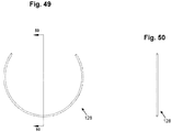
- the secondary fastening ring 32 may include features substantially similar to, but distinguishable from, those of the primary fastening ring 28.
- secondary fastening ring 32 may include ear members 610 extending from an outer circumference 620.
- the ear members 610 similar to ear members 410 on the primary fastening ring 28, may be configured to feed into cavities 93 in retaining cap 34 to prevent rotation of secondary fastening ring 32.
- Secondary fastening ring 32 may also include teeth 630 extending from an inner circumference 640. Teeth 630 may be configured to engage with, for example, a portion of pipe (e.g., pipe 36) inserted into the device 10.
- a spring 42 can be installed around bolt main body 65.
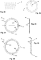
- Spring 42 is shown in greater detail in Figs. 25-26 .
- spring 42 may include a radially inwardly extending tab 43 that may be configured to fit within spring receiving hole 699 on bolt element 40. The tab 43 enables the spring to transfer its energy to the bolt when compressed.
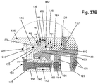
- first notch 505 is formed by surfaces 181 and 182.
- An axially exterior second notch 187 is formed at the joint of surfaces 188 and 497, and an axially interior, radially interior third notch 511 is formed by surfaces 384 and 399.
- the first notch 505 securely pinches and retains a portion of sealing member 124 when the cap 130 is secured to the body connector 120, as shown in Fig. 37B .
Landscapes
- Engineering & Computer Science (AREA)
- General Engineering & Computer Science (AREA)
- Mechanical Engineering (AREA)
- Quick-Acting Or Multi-Walled Pipe Joints (AREA)
- Gasket Seals (AREA)
Claims (13)
- Ensemble joint de tuyaux de verrouillage, comprenant :un connecteur de corps central (20, 120) ayant une face externe (23, 421), une face de paroi d'extrémité axiale (49, 158), et une face intérieure (71, 170) formant une cavité (73, 424) s'étendant à travers le connecteur de corps (20, 120) le long d'un axe de connecteur de corps central ;un capuchon de retenue (34, 130) ayant une paroi s'étendant radialement (907) et une paroi s'étendant axialement (195), chacune des parois s'étendant radialement et axialement (907, 195) ayant des faces intérieures et extérieures (930, 932, 931, 933), la paroi s'étendant axialement (195) du capuchon de retenue étant conçue pour se visser dans le connecteur de corps central (20, 120) de sorte que l'axe de connecteur de corps central et l'axe de capuchon de retenue soient coaxiaux ; etun premier système de garniture (50, 150) inséré dans la face intérieure du capuchon de retenue (932) de la paroi s'étendant axialement et la face intérieur du connecteur de corps (71, 170), après quoi le capuchon de retenue (34, 130) se visse dans le connecteur de corps central (20, 120), le premier système de garniture (50, 150) est comprimé, le premier système de garniture (50, 150) comprenant au moins un élément d'étanchéité (24, 124) et un dispositif de fixation de bague d'étanchéité (26, 126), le dispositif de fixation de bague d'étanchéité (26, 126) ayant une face extérieure axiale (386) ayant une saillie de support (488) positionnée radialement vers l'intérieur d'une pointe radialement extérieure (487), la face axialement extérieure (386) comprenant une face de bord inférieure (188) s'étendant axialement vers l'intérieur et radialement vers l'extérieur à partir d'une pointe externe radialement intérieure (498), et comprenant en outre une face de bord supérieur (497) s'étendant axialement vers l'intérieur et radialement vers l'intérieur à partir de la saillie de support (488) de sorte que la face de bord supérieur (497) rejoigne la face de bord inférieur (188) au niveau d'une encoche (187) ;caractérisé en ce que le connecteur de corps central (20, 120) comprend en outre un bord (77, 177) formé de manière à s'étendre radialement vers l'intérieur à partir de la face de paroi intérieure (71, 170) et un bloc (52, 125) s'étendant radialement vers l'extérieur à partir de la face extérieure (23, 421), le bloc (52, 125) étant pourvu d'au moins une ouverture (129) ayant une face intérieure, eten ce que le capuchon de retenue (34, 130) comprend en outre un bloc de retenue de boulon (92, 192) pourvu d'un boulon et s'étendant radialement vers l'extérieur à partir de la face extérieure de paroi s'étendant axialement (933), avec le bloc de retenue de boulon (92, 192) formant une cavité de retenue de boulon (98, 198), la face intérieure (932) de paroi s'étendant axialement du capuchon de retenue formant une cavité (96, 196) s'étendant par le capuchon de retenue (34, 130) le long de l'axe du capuchon de retenue.
- Ensemble selon la revendication 1, comprenant en outre un élément de boulon (40, 140) fixant ensemble le connecteur de corps central (20, 120) et le capuchon de retenue (34, 130), l'élément de boulon (40, 140) s'étendant à travers la cavité de retenue de boulon (98, 198) du capuchon de retenue (34, 130) et la face intérieure de ladite ouverture (129) dans le bloc (52, 125) s'étendant radialement vers l'extérieur de la face extérieure du connecteur de corps (23, 421).
- Ensemble selon la revendication 1, comprenant en outre une première bague de fixation (28) retenue contre la face de paroi intérieure de connecteur de corps (71, 170).
- Ensemble selon la revendication 3, comprenant en outre une seconde bague de fixation (32) retenue contre la face intérieure de paroi s'étendant radialement de capuchon de retenue (930).
- Ensemble selon la revendication 1, ledit élément d'étanchéité (24, 124) comprenant un joint racleur (22, 122) venant en butée contre la face de paroi intérieure (71, 170) du connecteur de corps (20, 120).
- Ensemble selon la revendication 1, ledit élément d'étanchéité (24, 124) comprenant une bague d'étanchéité (24, 124) venant en butée contre le dispositif de retenue de bague d'étanchéité (26, 126) et la face de paroi intérieure (71, 170) du connecteur de corps (20, 120).
- Ensemble selon la revendication 1, comprenant en outre une première bague de fixation (28) retenue contre la face de paroi intérieure de connecteur de corps (71, 170) et une seconde bague de fixation (32) retenue contre la face intérieure de paroi s'étendant radialement du capuchon de retenue (930), et ledit élément d'étanchéité (24, 124) comprenant un joint racleur (22, 122) venant en butée contre la face de paroi intérieure (71, 170) du connecteur de corps (20, 120) et une bague d'étanchéité (24, 124) venant en butée contre le dispositif de retenue de bague d'étanchéité (26, 126) et la face de paroi intérieure (71, 170) du connecteur de corps (20, 120).
- Ensemble selon la revendication 1, la face intérieure de paroi s'étendant radialement (930) du capuchon de retenue (34, 130) comprenant un col (909) s'étendant radialement vers l'intérieur entre la face intérieure de paroi s'étendant axialement (932) et une partie tête (915), la partie tête (915) ayant une saillie (913) formée en son sein qui s'étend axialement vers l'intérieur du col (909).
- Ensemble selon la revendication 1, le dispositif de fixation de bague d'étanchéité (26, 126) comprenant un corps ayant une face intérieure s'étendant radialement (180), une face médiane s'étendant vers l'extérieur radialement (182), et une face de lèvre s'étendant axialement (181) s'étendant entre une lèvre extérieure radialement (480) de la face intérieure s'étendant radialement (180) et une pointe radialement intérieure (482) de la face médiane s'étendant radialement vers l'extérieur (182).
- Ensemble selon la revendication 9, le dispositif de retenue de bague d'étanchéité (26, 126) comprenant en outre une face de rampe (183) s'étendant à la fois axialement et radialement vers l'extérieur à partir de la pointe radialement extérieure (480) de la face médiane (182) et une pointe externe radialement intérieure (485), et une face de support de base (185) s'étendant axialement vers l'extérieur à partir de la pointe externe radialement intérieure (485) et la pointe externe radialement extérieure (487).
- Ensemble selon la revendication 10, le corps de retenue de bague d'étanchéité comprenant en outre une face de base (186) s'étendant radialement vers l'extérieur à partir de la saillie de support (488) vers la pointe externe radialement extérieure (487), et le corps comprenant en outre une partie radialement intérieure (490) ayant des premières et des secondes parois s'étendant radialement vers l'extérieur (380, 381) partageant une paroi commune s'étendant axialement (184), les parois s'étendant radialement vers l'extérieur (380, 381) et la paroi s'étendant axialement (184) formant une rainure sur la circonférence (387).
- Ensemble selon la revendication 1, le système de garniture (50, 150) comprenant des premières et des secondes bagues de retenue (28, 32).
- Ensemble selon la revendication 12, la seconde bague de fixation (32) ayant une base avec une face de paroi radialement extérieure, une face de paroi axialement extérieure et une face de paroi axialement extérieure, et la face de paroi axialement extérieure venant en butée contre la face intérieure de capuchon de retenue (932), et la face de paroi axialement intérieure venant en butée contre la face de paroi d'extrémité axiale (49, 158) du connecteur de corps (20, 120).
Applications Claiming Priority (3)
| Application Number | Priority Date | Filing Date | Title |
|---|---|---|---|
| US201562221941P | 2015-09-22 | 2015-09-22 | |
| US15/001,986 US9562637B1 (en) | 2015-09-22 | 2016-01-20 | Locking pipe joint assembly, device and method |
| PCT/US2016/051879 WO2017053166A1 (fr) | 2015-09-22 | 2016-09-15 | Ensemble , dispositif et procédé de raccord de tuyau verrouillable |
Publications (3)
| Publication Number | Publication Date |
|---|---|
| EP3353457A1 EP3353457A1 (fr) | 2018-08-01 |
| EP3353457A4 EP3353457A4 (fr) | 2019-08-21 |
| EP3353457B1 true EP3353457B1 (fr) | 2020-11-11 |
Family
ID=57908713
Family Applications (1)
| Application Number | Title | Priority Date | Filing Date |
|---|---|---|---|
| EP16849367.4A Active EP3353457B1 (fr) | 2015-09-22 | 2016-09-15 | Ensemble de raccord de tuyau verrouillable |
Country Status (5)
| Country | Link |
|---|---|
| US (2) | US9562637B1 (fr) |
| EP (1) | EP3353457B1 (fr) |
| CN (1) | CN108027094B (fr) |
| CA (2) | CA2999473C (fr) |
| WO (1) | WO2017053166A1 (fr) |
Families Citing this family (22)
| Publication number | Priority date | Publication date | Assignee | Title |
|---|---|---|---|---|
| US10337547B2 (en) * | 2015-09-24 | 2019-07-02 | Gem Products, Inc. | Outrigger clamp |
| US10575512B2 (en) * | 2015-09-24 | 2020-03-03 | Gem Products, Inc. | Outrigger clamp with attachment point |
| US20180023733A1 (en) * | 2016-07-19 | 2018-01-25 | Wen Sheng Fu Co., Ltd | Pipe adapter |
| US9671049B1 (en) * | 2016-07-27 | 2017-06-06 | Quick Fitting, Inc. | Hybrid push-to-connect fitting device and assembly |
| US10463995B2 (en) * | 2016-09-30 | 2019-11-05 | Roberts Marketing De, Inc. | Apparatus and method for removing impurities from water or wastewater |
| TWM544036U (zh) * | 2017-02-15 | 2017-06-21 | Thermaltake Technology Co Ltd | 管接頭結構 |
| US20190219207A1 (en) | 2018-01-16 | 2019-07-18 | Rain Bird Corporation | Push To Connect Coupling |
| CN108758126B (zh) * | 2018-06-16 | 2019-11-05 | 马鞍山小古精密机电科技有限公司 | 一种用于环保设备的废气处理输送装置 |
| CN109291357A (zh) * | 2018-09-12 | 2019-02-01 | 东港市远东节水灌溉设备有限公司 | 一种线性低密度聚乙烯阻燃管及其制作方法 |
| KR102005741B1 (ko) * | 2018-12-27 | 2019-07-31 | (주)준성이엔씨 | 수도배관 이음구 |
| JP7357350B2 (ja) * | 2019-11-19 | 2023-10-06 | 株式会社タブチ | 管継手 |
| US10969047B1 (en) | 2020-01-29 | 2021-04-06 | Quick Fitting Holding Company, Llc | Electrical conduit fitting and assembly |
| WO2021154233A1 (fr) * | 2020-01-29 | 2021-08-05 | Quick Fitting, Inc. | Raccord et ensemble de conduit électrique |
| CN112128489B (zh) * | 2020-09-10 | 2022-06-14 | 广东电网有限责任公司梅州供电局 | 一种可拆卸式绝缘接头 |
| CN112984261A (zh) * | 2021-02-04 | 2021-06-18 | 李斌 | 一种用于水下pvc管道 |
| US11105452B1 (en) | 2021-02-25 | 2021-08-31 | Quick Fitting Holding Company, Llc | Push-to-connect joint assembly and device |
| CA3115319C (fr) * | 2021-04-15 | 2021-10-12 | Integrity Products & Supplies Inc. | Courroie de bride |
| US11262011B1 (en) * | 2021-05-17 | 2022-03-01 | Quick Fitting Holding Company, Llc | Swage connector device, assembly and method |
| USD1053320S1 (en) * | 2021-10-08 | 2024-12-03 | Quick Fitting Holding Company, Llc | Fitting |
| CN114688365B (zh) * | 2022-04-12 | 2025-03-25 | 江苏迪威高压科技股份有限公司 | 一种用于高压管件连接的连接结构及其连接方法 |
| US12345359B2 (en) | 2022-10-12 | 2025-07-01 | Rain Bird Corporation | Tube coupling |
| CN120969598B (zh) * | 2025-10-20 | 2026-01-30 | 航天晨光(福建)管业科技有限公司 | 一种大口径特种复合rtp管道快速安装装置 |
Family Cites Families (165)
| Publication number | Priority date | Publication date | Assignee | Title |
|---|---|---|---|---|
| US1822056A (en) | 1929-02-07 | 1931-09-08 | Gillette Vibber Company Inc | Threadless pipe connecter |
| US2132636A (en) | 1937-03-30 | 1938-10-11 | Johns Manville | Pipe assembly |
| US2230098A (en) | 1938-06-30 | 1941-01-28 | Patex Sa | Coupling for tubes and pipes |
| US2201372A (en) | 1938-11-26 | 1940-05-21 | Vernon Tool Co Ltd | Pipe coupling |
| GB564183A (en) * | 1943-06-12 | 1944-09-15 | T C Enstone & Company Successo | Improvements in pipe couplings |
| US2456203A (en) | 1943-08-21 | 1948-12-14 | Grinnell Corp | Coupling for tubular members |
| US2450527A (en) | 1945-10-27 | 1948-10-05 | P & V Quicklocking Co | Semiautomatic coupling |
| US2529821A (en) | 1947-05-09 | 1950-11-14 | Marion A Knapp | High-pressure coupling |
| US2701149A (en) | 1952-04-29 | 1955-02-01 | Kreidel Hans | Compressed wedge pipe coupling |
| US2774616A (en) | 1953-05-07 | 1956-12-18 | Roy F Dodd | Quick release coupling having detachable screw thimble-gland |
| NL121817C (fr) | 1958-09-12 | |||
| US2917075A (en) | 1959-06-15 | 1959-12-15 | A W Cash Valve Mfg Corp | Flow control valve |
| US3064983A (en) | 1959-08-27 | 1962-11-20 | Dresser Ind | Pipe joint |
| US3060959A (en) | 1960-07-07 | 1962-10-30 | Olin Mathieson | Excess flow cut-off valve |
| US3140107A (en) | 1960-11-28 | 1964-07-07 | Earl E Howe | Tube coupling having sealing and anchoring means |
| US3145730A (en) | 1963-03-07 | 1964-08-25 | Frank G Presnell | Control valve |
| US3428337A (en) | 1966-09-09 | 1969-02-18 | Owens Illinois Inc | Pipe coupling |
| US3434745A (en) | 1967-04-13 | 1969-03-25 | Smith Corp A O | Pipe coupling having a split ring locking means |
| US3365219A (en) | 1967-05-25 | 1968-01-23 | Eclipse Fuel Eng Co | Pressure fitting for a tube joint |
| CH506743A (de) | 1969-06-11 | 1971-04-30 | Schmid Kranz & Co Gmbh Zweigni | Rohrverbindungsmuffe für die mechanisch gesicherte Klemmbefestigung glatter Rohrenden - insbesondere kleinkalibriger Stahlrohre |
| US3709526A (en) | 1971-03-01 | 1973-01-09 | Baxter Laboratories Inc | Multiple piece clamp for connecting tubing |
| US3821670A (en) | 1972-05-01 | 1974-06-28 | Hughes Aircraft Co | Waveguide alignment and quick disconnect coupler |
| US3805824A (en) | 1972-09-25 | 1974-04-23 | Us Navy | Pressure-compensated flow control valve |
| US3915480A (en) | 1972-10-31 | 1975-10-28 | Dresser Ind | Pullout resistant pipe coupling member and gaskets therefor |
| US3837687A (en) | 1972-12-29 | 1974-09-24 | G Leonard | Coupling for tubing |
| US3885821A (en) | 1973-12-05 | 1975-05-27 | Gen Signal Corp | Expansion fitting |
| US3917324A (en) * | 1974-04-19 | 1975-11-04 | Toyo Kinzoku Corp | Pipe joint |
| US4009592A (en) | 1976-02-09 | 1977-03-01 | Ford Motor Company | Multiple stage expansion valve for an automotive air conditioning system |
| US4146254A (en) | 1976-03-31 | 1979-03-27 | Bristol Products, Inc. | Coupler for tubing |
| US4067361A (en) | 1976-04-21 | 1978-01-10 | The United States Of America As Represented By The Secretary Of The Navy | Silent self-controlled orificial restrictor |
| US4123090A (en) | 1976-07-19 | 1978-10-31 | Imperial-Eastman Corporation | Push-pull fitting |
| US4083586A (en) | 1976-11-12 | 1978-04-11 | Gordon H. Cork | Tube coupling |
| US4178023A (en) | 1977-02-09 | 1979-12-11 | Guest John D | Couplings for tubes |
| JPS5814311Y2 (ja) | 1977-11-22 | 1983-03-22 | 株式会社クボタ | 管継手部構造 |
| US4508369A (en) | 1978-06-02 | 1985-04-02 | Nycoil Corporation | Releasable coupling device |
| US4440424A (en) | 1978-06-02 | 1984-04-03 | Nycoil Corporation | Releasable coupling device |
| US4305606A (en) | 1978-11-24 | 1981-12-15 | Societe Legris France S.A. | Quick-releasable connectors for flexible plastic pipes |
| US4220361A (en) | 1979-02-01 | 1980-09-02 | The Aro Corporation | Connector for plastic tubing |
| US4288113A (en) | 1979-07-06 | 1981-09-08 | Parker-Hannifin Corporation | Quick connector coupling for semi-rigid hose |
| US4480729A (en) | 1979-10-03 | 1984-11-06 | P. L. Porter Company | Anti-surge valve for hydraulic locking device |
| US4466640A (en) | 1981-08-05 | 1984-08-21 | Dresser Industries, Inc. | Pullout resistant pipe coupling |
| JPS5830568A (ja) | 1981-08-19 | 1983-02-23 | Oval Eng Co Ltd | 定流量弁 |
| US4383552A (en) | 1981-10-16 | 1983-05-17 | Multi-Products Company | Adjustable choke |
| US4593943A (en) | 1983-08-23 | 1986-06-10 | Kabushiki Kaisha Nihon Pisco | Tubing joint |
| GB2146400A (en) | 1983-09-09 | 1985-04-17 | Imi Norgren Enots Ltd | Pipe coupling |
| US4606565A (en) * | 1983-09-12 | 1986-08-19 | Coupling Systems, Inc. | Pipe couplings |
| GB2160279B (en) | 1984-06-13 | 1987-08-19 | Hawke Cable Glands Ltd | Releasable pipe coupling |
| CH665700A5 (de) | 1984-07-10 | 1988-05-31 | Cejn Ag | Loesbare steckmuffen-rohrverbindung. |
| US4637636A (en) | 1984-11-12 | 1987-01-20 | Guest John D | Tube couplings |
| US4637640A (en) | 1985-02-27 | 1987-01-20 | Aeroquip Corporation | Push-in connect fitting |
| US4685706A (en) | 1985-03-04 | 1987-08-11 | Clevite Industries Inc. | Releasable push-to-connect tube fitting |
| GB2172948B (en) | 1985-03-28 | 1988-07-06 | Guest John D | Improvements in or relating to tube couplers |
| IT8583626A0 (it) | 1985-11-25 | 1985-11-25 | Vulcano Di Pozzi Gian Carlo | Raccordo autobloccante "unisex" col "clik" per attacco rapido di tubi in materiale plastico. |
| US4802696A (en) | 1986-10-23 | 1989-02-07 | The Gates Rubber Company | Quick connect coupling |
| GB2197409B (en) * | 1986-10-31 | 1990-08-22 | Kitz Corp | Pipe joint |
| FR2607573B1 (fr) | 1986-11-28 | 1989-03-31 | Parker Hannifin Rak Sa | Perfectionnement aux dispositifs de raccordement rapide pour tubes souples, semi-rigides ou rigides |
| GB2206660A (en) | 1987-07-06 | 1989-01-11 | Mie Horo Co Ltd | Pipe joint |
| AU625533B2 (en) | 1987-10-12 | 1992-07-16 | William James Irwin | Pipe connections |
| US4878697A (en) | 1987-10-14 | 1989-11-07 | Dresser Industries, Inc. | Compression coupling for plastic pipe |
| DE3806404C2 (de) | 1988-02-29 | 1994-06-09 | Raymond A Gmbh & Co Kg | Lösbare Steckverbindung für halbstarre Rohre |
| IT1216491B (it) | 1988-03-22 | 1990-03-08 | Finimpresa Spa | Raccordo di collegamento rapido per tubi flessibili con anello conico di trattenuta. |
| US4867198A (en) | 1988-10-11 | 1989-09-19 | Faust Bobby G | Adjustable flow regulating valve |
| US5024468A (en) | 1989-11-13 | 1991-06-18 | Parker Hannifin Corporation | Push-in tube fitting and release tool |
| JPH073119Y2 (ja) | 1989-11-20 | 1995-01-30 | シーケーディ株式会社 | 管継手 |
| US5010740A (en) | 1990-02-07 | 1991-04-30 | Carrier Corporation | Refrigeration system with mass flow limiting device |
| JPH0439492A (ja) | 1990-05-31 | 1992-02-10 | Tokai Rubber Ind Ltd | クイックコネクタ |
| US5084954A (en) | 1990-12-19 | 1992-02-04 | Itt Corporation | Quick connector universal release tool |
| DE4137396A1 (de) | 1991-11-14 | 1993-05-19 | Raymond A & Cie | Loesbare steckverbindung fuer halbstarre rohre |
| US5230539A (en) | 1991-12-31 | 1993-07-27 | Dana Corporation | Quick connect tube coupling |
| GB9204375D0 (en) | 1992-02-28 | 1992-04-08 | Guest John D | Improvements in or relating to tube couplings |
| US5284582A (en) | 1992-04-03 | 1994-02-08 | Yang Ming Tung | Fast connection joint of fitting outlet |
| US5251655A (en) | 1992-07-06 | 1993-10-12 | Wilshire Partners | Flow control valves for post-mix beverage dispensers |
| US5443289A (en) | 1992-11-11 | 1995-08-22 | Guest; John D. | Tube couplings |
| DE4304241C2 (de) | 1993-02-12 | 1995-08-31 | Hummel Anton Verwaltung | Steckverbindung für Rohre, Schläuche oder Rundkörper |
| FR2702818B1 (fr) | 1993-03-19 | 1995-06-02 | Legris Sa | Raccord à connexion instantanée à griffe. |
| GB9314094D0 (en) | 1993-07-08 | 1993-08-18 | Angell Jonathan G C | Releasable coupling |
| GB2286026B (en) | 1994-01-19 | 1997-08-06 | Guest John D | Improvements in or relating to grab rings |
| JP3044224B2 (ja) * | 1994-02-08 | 2000-05-22 | 郷田 元宏 | 管の接続構造 |
| US5425347A (en) | 1994-03-21 | 1995-06-20 | Bundy Corporation | Connector for exhaust gas recirculation tube |
| US5469882A (en) | 1994-12-14 | 1995-11-28 | Condon; Duane R. | Partially recessed valve fixture for connection to faucets and commodes |
| ATE195583T1 (de) | 1995-01-19 | 2000-09-15 | Legris Sa | Vorrichtung zum schnellen verbinden eines rohres mit einem starren element |
| DE19510193A1 (de) | 1995-03-21 | 1996-09-26 | Voss Armaturen | Anschlußvorrichtung für Rohrleitungen |
| JP3593382B2 (ja) | 1995-04-13 | 2004-11-24 | Smc株式会社 | 管継手 |
| US5524936A (en) | 1995-07-12 | 1996-06-11 | Control Systems, Inc. | Torque tight locking device |
| US5887911A (en) | 1995-10-13 | 1999-03-30 | Form Rite | Quick connect fluid coupling with a self-contained releasable collet retainer |
| US5865211A (en) | 1996-04-30 | 1999-02-02 | Masco Corporation Of Indiana | Faucet installation aid |
| FR2749639B1 (fr) | 1996-06-10 | 1998-08-21 | Hutchinson | Dispositif de raccord rapide pour conduit de fluide sous pression |
| GB2328259B (en) | 1997-08-14 | 2002-08-07 | Marley Extrusions | Push-fit tube couplings |
| DE29721760U1 (de) | 1997-12-10 | 1998-01-29 | Franz Viegener II GmbH & Co. KG, 57439 Attendorn | Unlösbare Preßverbindung zwischen einem Fitting und einem Metallrohrende |
| FR2772458B1 (fr) | 1997-12-11 | 2000-01-14 | Legris Sa | Dispositif de raccordement rapide d'un tube a un element rigide a bague anti-extraction et temoin d'integrite |
| EP1045183A4 (fr) | 1997-12-24 | 2004-03-31 | Mikuni Plastics Co Ltd | Tuyau de resine thermoplastique dure, structure de raccordement de tuyau et procedes de fabrication |
| AU2489899A (en) | 1998-01-29 | 1999-08-16 | Value Plastics, Inc. | An improved releasable collet type tube coupling system |
| JPH11325362A (ja) | 1998-05-13 | 1999-11-26 | Smc Corp | 管継手 |
| KR100302629B1 (ko) | 1998-07-10 | 2001-09-22 | 구장서 | 관이음매 |
| US5957509A (en) | 1998-10-16 | 1999-09-28 | Komolrochanaporn; Naris | Pipe coupling |
| US5996632A (en) | 1998-12-14 | 1999-12-07 | Aeroquip Corporation | Pressure relief adapter |
| JP3372886B2 (ja) | 1999-02-18 | 2003-02-04 | エスエムシー株式会社 | 管継手 |
| US6502866B1 (en) * | 1999-05-26 | 2003-01-07 | Osaka Gas Co., Ltd. | One-touch joint for flexible tube |
| IT247350Y1 (it) | 1999-06-22 | 2002-07-09 | Olab Srl | Raccordo rapido per tubi. |
| JP4213303B2 (ja) | 1999-07-22 | 2009-01-21 | 株式会社パイオラックス | 管継手 |
| DE60011359T2 (de) | 1999-09-27 | 2005-06-16 | Legris S.A. | Vorrichtung zum Verbinden von einem Leitungsende mit einem Anschlussteil |
| US6343814B1 (en) | 1999-11-08 | 2002-02-05 | Ti Group Automotive Systems, Llc | Insertion verifier dust cap |
| US6685230B1 (en) | 2000-07-26 | 2004-02-03 | Olab S.R.L. | Rapid connection for tubes |
| DE20017921U1 (de) | 2000-10-19 | 2002-02-28 | Armaturenfabrik Hermann Voss GmbH + Co. KG, 51688 Wipperfürth | Anschlußvorrichtung für Druckmittel-Rohre |
| US7178836B2 (en) | 2001-02-27 | 2007-02-20 | Dana Corporation | Fluid couplings |
| US6536470B1 (en) | 2001-04-27 | 2003-03-25 | Wayne J. Carn | Back flow prevention valve |
| JP2002353611A (ja) | 2001-05-25 | 2002-12-06 | Hakko Kk | ホットエアー用着脱ノズル |
| FR2830071B1 (fr) | 2001-09-21 | 2003-11-14 | Legris Sa | Dispositif de raccordement instantane |
| KR200267995Y1 (ko) | 2001-09-22 | 2002-03-15 | 구성준 | 파이프 연결구조 |
| DE10162657B4 (de) | 2001-12-20 | 2004-06-17 | Festo Ag & Co. | Anschlussstück für Fluidleitungen sowie damit ausgestattetes fluidtechnisches Gerät |
| JP4288314B2 (ja) | 2002-03-22 | 2009-07-01 | Smc株式会社 | 管継手 |
| GB0209897D0 (en) | 2002-04-30 | 2002-06-05 | Guest John Int Ltd | Improvements in or relating to tube couplings |
| US6843516B2 (en) | 2002-07-15 | 2005-01-18 | H-P Products, Inc. | Coupler for low pressure piping system |
| US6988746B2 (en) * | 2002-10-09 | 2006-01-24 | Olson Mark H | Nut type raintight threadless couplings and connectors for electrical conduits |
| JP4110520B2 (ja) | 2002-10-23 | 2008-07-02 | Smc株式会社 | 管継手 |
| FR2851634B1 (fr) | 2003-01-31 | 2006-05-19 | Tokai Rubber Ind Ltd | Pince de raccord et structure de raccordement de raccord destinees a verifier le raccordement complet entre un raccord et un tuyau |
| US6988509B2 (en) | 2003-03-17 | 2006-01-24 | Carleton Technologies, Inc. | Riser line shutoff valve |
| US7021672B2 (en) | 2003-05-29 | 2006-04-04 | Orbit Irrigation Products, Inc. | Irrigation coupling apparatus and method |
| FR2860572B1 (fr) | 2003-10-02 | 2005-12-16 | Comap | Dispositif de demontage pour connexion instantanee |
| US20050194785A1 (en) * | 2003-10-03 | 2005-09-08 | Sami Shemtov | Rain tight compression fitting coupling device |
| CN1324258C (zh) | 2003-10-14 | 2007-07-04 | 安业环球有限公司 | 水或汽管连接装置 |
| US6824172B1 (en) | 2003-10-14 | 2004-11-30 | Naris Komolrochanaporn | Push-pull pipe coupling |
| FR2866095B1 (fr) | 2004-02-05 | 2007-09-28 | Legris Sa | Rondelle pour dispositif de raccordement de tube, procede de fabrication de rondelle et dispositif de raccordement |
| FR2869385B1 (fr) | 2004-04-27 | 2006-11-03 | Legris Sa | Element de circuit de transport de fluide equipe d'un dispositif de raccordement de type cartouche |
| DE202004007291U1 (de) | 2004-05-07 | 2005-09-15 | Viega Gmbh & Co Kg | Pressverbindungsanordnung |
| GB0411099D0 (en) | 2004-05-19 | 2004-06-23 | Oystertec Plc | Pipe fitting |
| JP2006010010A (ja) | 2004-06-29 | 2006-01-12 | Smc Corp | 管継手 |
| FR2873185B1 (fr) | 2004-07-19 | 2008-03-14 | Parker Hannifin France Sas Soc | Cartouche d'implantation pour un raccord de tuyau destine a prendre place dans un logement |
| WO2006012598A1 (fr) | 2004-07-21 | 2006-02-02 | Parker-Hannifin Corporation | Adaptateur et procede pour la conversion de raccord/acces pour tube standard en raccord/acces pour tube a emboitement par poussee |
| DE102004046548B3 (de) | 2004-09-20 | 2005-06-23 | Festo Ag & Co. | Anschlussvorrichtung für Fluidleitungen |
| US7509971B2 (en) | 2005-02-08 | 2009-03-31 | Kohler Co. | Valve assembly with compliant escutcheon |
| GB0504899D0 (en) | 2005-03-09 | 2005-04-13 | Guest John Int Ltd | Improvements in or relating to tube couplings |
| US7850208B2 (en) | 2005-12-14 | 2010-12-14 | Parker-Hannifin Corporation | Stamped collet for push-to-connect tube fittings |
| EP1847753B1 (fr) | 2006-04-19 | 2008-11-05 | IBP Conex Limited | Joint circulaire avec indicateur de fuite et montage équipé dudit joint |
| US7686346B1 (en) | 2006-07-21 | 2010-03-30 | Elkhart Products Corporation | Transition tee coupling |
| US7954861B2 (en) | 2007-02-23 | 2011-06-07 | The Gates Corporation | Crimped/swaged-on tubing terminations and methods |
| US8205915B1 (en) | 2007-05-25 | 2012-06-26 | Quick Fitting, Inc. | Piping joint assembly system and method |
| US8480134B2 (en) | 2007-05-25 | 2013-07-09 | Quick Fitting, Inc. | Piping joint assembly system and method with sealing ring stabilizer |
| US7862089B2 (en) | 2007-05-25 | 2011-01-04 | Quick Fitting, Inc. | Piping joint assembly system and method |
| JP4992098B2 (ja) | 2007-06-05 | 2012-08-08 | 株式会社水研 | ノンボルト継手構造およびノンボルト継手構造を形成する方法 |
| DE112008001699T5 (de) | 2007-06-26 | 2010-06-10 | Swagelok Co., Solon | Leitungsverbindung mit Sensorfunktion |
| US7878555B2 (en) * | 2007-07-18 | 2011-02-01 | Kofulso Co., Ltd. | Coupling device for circular pipes |
| US7942161B2 (en) | 2007-09-05 | 2011-05-17 | Quick Fitting, Inc. | Push-fit valve with integrated mounting assembly |
| FR2923888B1 (fr) | 2007-11-15 | 2014-01-17 | Legris Sa | Dispositif de raccordement rapide d'un tube avec bague de securite |
| US7530606B1 (en) | 2008-01-04 | 2009-05-12 | Richard Yang | Quick pipe connector |
| US20090315327A1 (en) * | 2008-06-23 | 2009-12-24 | Christopher David Plucker | Anti-rotation locking device for tube unions |
| US7644955B1 (en) | 2008-07-03 | 2010-01-12 | Naris Komolrochanaporn | Quick coupling type fitting |
| CN101329000B (zh) | 2008-07-11 | 2012-10-03 | 多升投资有限公司 | 流体管连接装置及其配套的拆管工具 |
| DE102009007303B4 (de) | 2009-02-03 | 2023-05-04 | Viega Technology Gmbh & Co. Kg | Fitting für dickwandige Rohre |
| FR2945606A1 (fr) | 2009-05-18 | 2010-11-19 | Legris Sas | Dispositif de raccordement rapide pour circuits de fluide pouvant subir d'importantes variations de pression. |
| EP2256394A1 (fr) | 2009-05-29 | 2010-12-01 | Wavin B.V. | Outil de démontage pour un raccord de tuyau enfichable |
| US8585100B2 (en) | 2009-08-27 | 2013-11-19 | Elkhart Products Corporation | Press-connect fitting with improved grab ring function |
| EP2472160B1 (fr) | 2009-12-16 | 2015-08-26 | GSA Industries (Aust.) Pty Ltd | Couplage de tubes |
| US9441771B2 (en) * | 2010-02-26 | 2016-09-13 | Mueller International, Llc | Pipe coupling device |
| CN102330723A (zh) * | 2010-07-13 | 2012-01-25 | 新秩序投资119股份有限公司 | 管配件 |
| US8398122B2 (en) | 2010-12-30 | 2013-03-19 | Quick Fitting, Inc. | Push connect joint assembly, system and method |
| CN202100798U (zh) | 2011-04-27 | 2012-01-04 | 润联(天津)五金工具有限公司 | 多用球阀 |
| US8894100B2 (en) * | 2012-03-16 | 2014-11-25 | Romac Industries, Inc. | Fitting with draw mechanism |
| CN202493819U (zh) * | 2012-03-26 | 2012-10-17 | 金日 | 插入式管接头 |
| US9343883B2 (en) * | 2013-03-14 | 2016-05-17 | Bridgeport Fittings, Inc. | Raintight compression connector and raintight compression coupler for securing electrical metallic tubing or rigid metallic conduit |
| US8844981B1 (en) | 2013-06-06 | 2014-09-30 | Quick Fitting, Inc. | Push-to-connect joint assembly, device and method |
| KR20150008557A (ko) * | 2013-07-15 | 2015-01-23 | 김칠현 | 나사식 금속관이음쇠의 접속구조 |
| US8844974B1 (en) | 2013-12-31 | 2014-09-30 | Quick Fitting, Inc. | Cross platform grip ring release device and method |
| GB2525879A (en) * | 2014-05-07 | 2015-11-11 | Pegler Yorkshire Group Ltd | Push-fit pipe couplings |
| US9068680B1 (en) | 2014-05-30 | 2015-06-30 | Quick Fitting, Inc. | Push-to-connect fitting integrated packing arrangement, device and methods |
-
2016
- 2016-01-20 US US15/001,986 patent/US9562637B1/en active Active
- 2016-09-15 EP EP16849367.4A patent/EP3353457B1/fr active Active
- 2016-09-15 CN CN201680054468.6A patent/CN108027094B/zh not_active Expired - Fee Related
- 2016-09-15 CA CA2999473A patent/CA2999473C/fr active Active
- 2016-09-15 CA CA3045362A patent/CA3045362C/fr active Active
- 2016-09-15 WO PCT/US2016/051879 patent/WO2017053166A1/fr not_active Ceased
- 2016-12-21 US US15/386,892 patent/US9816656B2/en active Active
Non-Patent Citations (1)
| Title |
|---|
| None * |
Also Published As
| Publication number | Publication date |
|---|---|
| CA2999473C (fr) | 2019-07-16 |
| CN108027094A (zh) | 2018-05-11 |
| US9562637B1 (en) | 2017-02-07 |
| US20170205003A1 (en) | 2017-07-20 |
| WO2017053166A1 (fr) | 2017-03-30 |
| US9816656B2 (en) | 2017-11-14 |
| EP3353457A1 (fr) | 2018-08-01 |
| CA3045362A1 (fr) | 2017-03-30 |
| CA2999473A1 (fr) | 2017-03-30 |
| EP3353457A4 (fr) | 2019-08-21 |
| CN108027094B (zh) | 2019-09-24 |
| CA3045362C (fr) | 2020-02-25 |
Similar Documents
| Publication | Publication Date | Title |
|---|---|---|
| CA3045362C (fr) | Ensemble, dispositif et procede de raccord de tuyau verrouillable | |
| US9920866B2 (en) | Hybrid push-to-connect fitting, device and assembly | |
| US8480134B2 (en) | Piping joint assembly system and method with sealing ring stabilizer | |
| US9816655B2 (en) | Rotation locking push-to-connect fitting device, system and method | |
| US9574691B1 (en) | Hybrid push-to-connect fitting device, arrangement and method | |
| US8205915B1 (en) | Piping joint assembly system and method | |
| EP4298368B1 (fr) | Ensemble de joint à assemblage par poussée | |
| EP3271632B1 (fr) | Raccord à connexion par poussée avec ensemble et dispositif d'assistance à la libération | |
| EP3004710B1 (fr) | Ensemble joint instantané, dispositif et procédé | |
| EP3535512B1 (fr) | Dispositif de conduit à verrouillage latéral et ensemble joint | |
| CN103975187B (zh) | 具有密封环稳定件的管道接头装配系统和方法 |
Legal Events
| Date | Code | Title | Description |
|---|---|---|---|
| STAA | Information on the status of an ep patent application or granted ep patent |
Free format text: STATUS: THE INTERNATIONAL PUBLICATION HAS BEEN MADE |
|
| PUAI | Public reference made under article 153(3) epc to a published international application that has entered the european phase |
Free format text: ORIGINAL CODE: 0009012 |
|
| STAA | Information on the status of an ep patent application or granted ep patent |
Free format text: STATUS: REQUEST FOR EXAMINATION WAS MADE |
|
| 17P | Request for examination filed |
Effective date: 20180419 |
|
| AK | Designated contracting states |
Kind code of ref document: A1 Designated state(s): AL AT BE BG CH CY CZ DE DK EE ES FI FR GB GR HR HU IE IS IT LI LT LU LV MC MK MT NL NO PL PT RO RS SE SI SK SM TR |
|
| AX | Request for extension of the european patent |
Extension state: BA ME |
|
| DAV | Request for validation of the european patent (deleted) | ||
| DAX | Request for extension of the european patent (deleted) | ||
| A4 | Supplementary search report drawn up and despatched |
Effective date: 20190724 |
|
| RIC1 | Information provided on ipc code assigned before grant |
Ipc: F16L 21/08 20060101ALI20190718BHEP Ipc: F16L 19/065 20060101ALI20190718BHEP Ipc: F16L 19/06 20060101ALI20190718BHEP Ipc: F16L 19/08 20060101ALI20190718BHEP Ipc: F16L 21/04 20060101AFI20190718BHEP Ipc: F16L 19/00 20060101ALI20190718BHEP |
|
| GRAP | Despatch of communication of intention to grant a patent |
Free format text: ORIGINAL CODE: EPIDOSNIGR1 |
|
| STAA | Information on the status of an ep patent application or granted ep patent |
Free format text: STATUS: GRANT OF PATENT IS INTENDED |
|
| RIC1 | Information provided on ipc code assigned before grant |
Ipc: F16L 19/00 20060101ALI20200518BHEP Ipc: F16L 21/04 20060101AFI20200518BHEP Ipc: F16L 19/065 20060101ALI20200518BHEP Ipc: F16L 19/08 20060101ALI20200518BHEP Ipc: F16L 21/08 20060101ALI20200518BHEP Ipc: F16L 19/06 20060101ALI20200518BHEP |
|
| INTG | Intention to grant announced |
Effective date: 20200605 |
|
| GRAS | Grant fee paid |
Free format text: ORIGINAL CODE: EPIDOSNIGR3 |
|
| GRAA | (expected) grant |
Free format text: ORIGINAL CODE: 0009210 |
|
| STAA | Information on the status of an ep patent application or granted ep patent |
Free format text: STATUS: THE PATENT HAS BEEN GRANTED |
|
| AK | Designated contracting states |
Kind code of ref document: B1 Designated state(s): AL AT BE BG CH CY CZ DE DK EE ES FI FR GB GR HR HU IE IS IT LI LT LU LV MC MK MT NL NO PL PT RO RS SE SI SK SM TR |
|
| REG | Reference to a national code |
Ref country code: GB Ref legal event code: FG4D |
|
| REG | Reference to a national code |
Ref country code: CH Ref legal event code: EP |
|
| REG | Reference to a national code |
Ref country code: AT Ref legal event code: REF Ref document number: 1333811 Country of ref document: AT Kind code of ref document: T Effective date: 20201115 |
|
| REG | Reference to a national code |
Ref country code: DE Ref legal event code: R096 Ref document number: 602016047838 Country of ref document: DE |
|
| REG | Reference to a national code |
Ref country code: IE Ref legal event code: FG4D |
|
| REG | Reference to a national code |
Ref country code: DE Ref legal event code: R082 Ref document number: 602016047838 Country of ref document: DE Representative=s name: WUESTHOFF & WUESTHOFF, PATENTANWAELTE PARTG MB, DE |
|
| REG | Reference to a national code |
Ref country code: DE Ref legal event code: R082 Ref document number: 602016047838 Country of ref document: DE Representative=s name: WUESTHOFF & WUESTHOFF, PATENTANWAELTE PARTG MB, DE Ref country code: DE Ref legal event code: R081 Ref document number: 602016047838 Country of ref document: DE Owner name: QUICK FITTING HOLDING COMPANY, LLC (N.D.GES.D., US Free format text: FORMER OWNER: QUICK FITTING, INC., WARWICK, R.I., US |
|
| REG | Reference to a national code |
Ref country code: NL Ref legal event code: MP Effective date: 20201111 |
|
| REG | Reference to a national code |
Ref country code: AT Ref legal event code: MK05 Ref document number: 1333811 Country of ref document: AT Kind code of ref document: T Effective date: 20201111 |
|
| PG25 | Lapsed in a contracting state [announced via postgrant information from national office to epo] |
Ref country code: GR Free format text: LAPSE BECAUSE OF FAILURE TO SUBMIT A TRANSLATION OF THE DESCRIPTION OR TO PAY THE FEE WITHIN THE PRESCRIBED TIME-LIMIT Effective date: 20210212 Ref country code: FI Free format text: LAPSE BECAUSE OF FAILURE TO SUBMIT A TRANSLATION OF THE DESCRIPTION OR TO PAY THE FEE WITHIN THE PRESCRIBED TIME-LIMIT Effective date: 20201111 Ref country code: NO Free format text: LAPSE BECAUSE OF FAILURE TO SUBMIT A TRANSLATION OF THE DESCRIPTION OR TO PAY THE FEE WITHIN THE PRESCRIBED TIME-LIMIT Effective date: 20210211 Ref country code: PT Free format text: LAPSE BECAUSE OF FAILURE TO SUBMIT A TRANSLATION OF THE DESCRIPTION OR TO PAY THE FEE WITHIN THE PRESCRIBED TIME-LIMIT Effective date: 20210311 Ref country code: RS Free format text: LAPSE BECAUSE OF FAILURE TO SUBMIT A TRANSLATION OF THE DESCRIPTION OR TO PAY THE FEE WITHIN THE PRESCRIBED TIME-LIMIT Effective date: 20201111 |
|
| PG25 | Lapsed in a contracting state [announced via postgrant information from national office to epo] |
Ref country code: AT Free format text: LAPSE BECAUSE OF FAILURE TO SUBMIT A TRANSLATION OF THE DESCRIPTION OR TO PAY THE FEE WITHIN THE PRESCRIBED TIME-LIMIT Effective date: 20201111 Ref country code: BG Free format text: LAPSE BECAUSE OF FAILURE TO SUBMIT A TRANSLATION OF THE DESCRIPTION OR TO PAY THE FEE WITHIN THE PRESCRIBED TIME-LIMIT Effective date: 20210211 Ref country code: IS Free format text: LAPSE BECAUSE OF FAILURE TO SUBMIT A TRANSLATION OF THE DESCRIPTION OR TO PAY THE FEE WITHIN THE PRESCRIBED TIME-LIMIT Effective date: 20210311 Ref country code: PL Free format text: LAPSE BECAUSE OF FAILURE TO SUBMIT A TRANSLATION OF THE DESCRIPTION OR TO PAY THE FEE WITHIN THE PRESCRIBED TIME-LIMIT Effective date: 20201111 Ref country code: LV Free format text: LAPSE BECAUSE OF FAILURE TO SUBMIT A TRANSLATION OF THE DESCRIPTION OR TO PAY THE FEE WITHIN THE PRESCRIBED TIME-LIMIT Effective date: 20201111 Ref country code: SE Free format text: LAPSE BECAUSE OF FAILURE TO SUBMIT A TRANSLATION OF THE DESCRIPTION OR TO PAY THE FEE WITHIN THE PRESCRIBED TIME-LIMIT Effective date: 20201111 |
|
| REG | Reference to a national code |
Ref country code: LT Ref legal event code: MG9D |
|
| RAP2 | Party data changed (patent owner data changed or rights of a patent transferred) |
Owner name: QUICK FITTING HOLDING COMPANY, LLC |
|
| PG25 | Lapsed in a contracting state [announced via postgrant information from national office to epo] |
Ref country code: HR Free format text: LAPSE BECAUSE OF FAILURE TO SUBMIT A TRANSLATION OF THE DESCRIPTION OR TO PAY THE FEE WITHIN THE PRESCRIBED TIME-LIMIT Effective date: 20201111 |
|
| REG | Reference to a national code |
Ref country code: GB Ref legal event code: 732E Free format text: REGISTERED BETWEEN 20210603 AND 20210609 |
|
| PG25 | Lapsed in a contracting state [announced via postgrant information from national office to epo] |
Ref country code: SM Free format text: LAPSE BECAUSE OF FAILURE TO SUBMIT A TRANSLATION OF THE DESCRIPTION OR TO PAY THE FEE WITHIN THE PRESCRIBED TIME-LIMIT Effective date: 20201111 Ref country code: LT Free format text: LAPSE BECAUSE OF FAILURE TO SUBMIT A TRANSLATION OF THE DESCRIPTION OR TO PAY THE FEE WITHIN THE PRESCRIBED TIME-LIMIT Effective date: 20201111 Ref country code: EE Free format text: LAPSE BECAUSE OF FAILURE TO SUBMIT A TRANSLATION OF THE DESCRIPTION OR TO PAY THE FEE WITHIN THE PRESCRIBED TIME-LIMIT Effective date: 20201111 Ref country code: CZ Free format text: LAPSE BECAUSE OF FAILURE TO SUBMIT A TRANSLATION OF THE DESCRIPTION OR TO PAY THE FEE WITHIN THE PRESCRIBED TIME-LIMIT Effective date: 20201111 Ref country code: SK Free format text: LAPSE BECAUSE OF FAILURE TO SUBMIT A TRANSLATION OF THE DESCRIPTION OR TO PAY THE FEE WITHIN THE PRESCRIBED TIME-LIMIT Effective date: 20201111 Ref country code: RO Free format text: LAPSE BECAUSE OF FAILURE TO SUBMIT A TRANSLATION OF THE DESCRIPTION OR TO PAY THE FEE WITHIN THE PRESCRIBED TIME-LIMIT Effective date: 20201111 |
|
| REG | Reference to a national code |
Ref country code: DE Ref legal event code: R097 Ref document number: 602016047838 Country of ref document: DE |
|
| PG25 | Lapsed in a contracting state [announced via postgrant information from national office to epo] |
Ref country code: DK Free format text: LAPSE BECAUSE OF FAILURE TO SUBMIT A TRANSLATION OF THE DESCRIPTION OR TO PAY THE FEE WITHIN THE PRESCRIBED TIME-LIMIT Effective date: 20201111 |
|
| PLBE | No opposition filed within time limit |
Free format text: ORIGINAL CODE: 0009261 |
|
| STAA | Information on the status of an ep patent application or granted ep patent |
Free format text: STATUS: NO OPPOSITION FILED WITHIN TIME LIMIT |
|
| 26N | No opposition filed |
Effective date: 20210812 |
|
| PG25 | Lapsed in a contracting state [announced via postgrant information from national office to epo] |
Ref country code: NL Free format text: LAPSE BECAUSE OF FAILURE TO SUBMIT A TRANSLATION OF THE DESCRIPTION OR TO PAY THE FEE WITHIN THE PRESCRIBED TIME-LIMIT Effective date: 20201111 Ref country code: AL Free format text: LAPSE BECAUSE OF FAILURE TO SUBMIT A TRANSLATION OF THE DESCRIPTION OR TO PAY THE FEE WITHIN THE PRESCRIBED TIME-LIMIT Effective date: 20201111 |
|
| PG25 | Lapsed in a contracting state [announced via postgrant information from national office to epo] |
Ref country code: SI Free format text: LAPSE BECAUSE OF FAILURE TO SUBMIT A TRANSLATION OF THE DESCRIPTION OR TO PAY THE FEE WITHIN THE PRESCRIBED TIME-LIMIT Effective date: 20201111 |
|
| PGFP | Annual fee paid to national office [announced via postgrant information from national office to epo] |
Ref country code: TR Payment date: 20210920 Year of fee payment: 6 |
|
| PG25 | Lapsed in a contracting state [announced via postgrant information from national office to epo] |
Ref country code: ES Free format text: LAPSE BECAUSE OF FAILURE TO SUBMIT A TRANSLATION OF THE DESCRIPTION OR TO PAY THE FEE WITHIN THE PRESCRIBED TIME-LIMIT Effective date: 20201111 |
|
| REG | Reference to a national code |
Ref country code: CH Ref legal event code: PL |
|
| REG | Reference to a national code |
Ref country code: BE Ref legal event code: MM Effective date: 20210930 |
|
| PG25 | Lapsed in a contracting state [announced via postgrant information from national office to epo] |
Ref country code: IS Free format text: LAPSE BECAUSE OF FAILURE TO SUBMIT A TRANSLATION OF THE DESCRIPTION OR TO PAY THE FEE WITHIN THE PRESCRIBED TIME-LIMIT Effective date: 20210311 Ref country code: MC Free format text: LAPSE BECAUSE OF FAILURE TO SUBMIT A TRANSLATION OF THE DESCRIPTION OR TO PAY THE FEE WITHIN THE PRESCRIBED TIME-LIMIT Effective date: 20201111 |
|
| PG25 | Lapsed in a contracting state [announced via postgrant information from national office to epo] |
Ref country code: LU Free format text: LAPSE BECAUSE OF NON-PAYMENT OF DUE FEES Effective date: 20210915 Ref country code: IE Free format text: LAPSE BECAUSE OF NON-PAYMENT OF DUE FEES Effective date: 20210915 Ref country code: BE Free format text: LAPSE BECAUSE OF NON-PAYMENT OF DUE FEES Effective date: 20210930 |
|
| PG25 | Lapsed in a contracting state [announced via postgrant information from national office to epo] |
Ref country code: LI Free format text: LAPSE BECAUSE OF NON-PAYMENT OF DUE FEES Effective date: 20210930 Ref country code: CH Free format text: LAPSE BECAUSE OF NON-PAYMENT OF DUE FEES Effective date: 20210930 |
|
| PG25 | Lapsed in a contracting state [announced via postgrant information from national office to epo] |
Ref country code: HU Free format text: LAPSE BECAUSE OF FAILURE TO SUBMIT A TRANSLATION OF THE DESCRIPTION OR TO PAY THE FEE WITHIN THE PRESCRIBED TIME-LIMIT; INVALID AB INITIO Effective date: 20160915 |
|
| PG25 | Lapsed in a contracting state [announced via postgrant information from national office to epo] |
Ref country code: CY Free format text: LAPSE BECAUSE OF FAILURE TO SUBMIT A TRANSLATION OF THE DESCRIPTION OR TO PAY THE FEE WITHIN THE PRESCRIBED TIME-LIMIT Effective date: 20201111 |
|
| PG25 | Lapsed in a contracting state [announced via postgrant information from national office to epo] |
Ref country code: MK Free format text: LAPSE BECAUSE OF FAILURE TO SUBMIT A TRANSLATION OF THE DESCRIPTION OR TO PAY THE FEE WITHIN THE PRESCRIBED TIME-LIMIT Effective date: 20201111 |
|
| PG25 | Lapsed in a contracting state [announced via postgrant information from national office to epo] |
Ref country code: MT Free format text: LAPSE BECAUSE OF FAILURE TO SUBMIT A TRANSLATION OF THE DESCRIPTION OR TO PAY THE FEE WITHIN THE PRESCRIBED TIME-LIMIT Effective date: 20201111 |
|
| PGFP | Annual fee paid to national office [announced via postgrant information from national office to epo] |
Ref country code: DE Payment date: 20240927 Year of fee payment: 9 |
|
| PGFP | Annual fee paid to national office [announced via postgrant information from national office to epo] |
Ref country code: GB Payment date: 20240927 Year of fee payment: 9 |
|
| PGFP | Annual fee paid to national office [announced via postgrant information from national office to epo] |
Ref country code: FR Payment date: 20240925 Year of fee payment: 9 |
|
| PGFP | Annual fee paid to national office [announced via postgrant information from national office to epo] |
Ref country code: IT Payment date: 20240919 Year of fee payment: 9 |