EP3353460B1 - Bouchon fileté - Google Patents
Bouchon fileté Download PDFInfo
- Publication number
- EP3353460B1 EP3353460B1 EP16757593.5A EP16757593A EP3353460B1 EP 3353460 B1 EP3353460 B1 EP 3353460B1 EP 16757593 A EP16757593 A EP 16757593A EP 3353460 B1 EP3353460 B1 EP 3353460B1
- Authority
- EP
- European Patent Office
- Prior art keywords
- screw
- flange
- base
- engagement means
- opening
- Prior art date
- Legal status (The legal status is an assumption and is not a legal conclusion. Google has not performed a legal analysis and makes no representation as to the accuracy of the status listed.)
- Active
Links
Images


Classifications
-
- F—MECHANICAL ENGINEERING; LIGHTING; HEATING; WEAPONS; BLASTING
- F16—ENGINEERING ELEMENTS AND UNITS; GENERAL MEASURES FOR PRODUCING AND MAINTAINING EFFECTIVE FUNCTIONING OF MACHINES OR INSTALLATIONS; THERMAL INSULATION IN GENERAL
- F16B—DEVICES FOR FASTENING OR SECURING CONSTRUCTIONAL ELEMENTS OR MACHINE PARTS TOGETHER, e.g. NAILS, BOLTS, CIRCLIPS, CLAMPS, CLIPS OR WEDGES; JOINTS OR JOINTING
- F16B31/00—Screwed connections specially modified in view of tensile load; Break-bolts
- F16B31/02—Screwed connections specially modified in view of tensile load; Break-bolts for indicating the attainment of a particular tensile load or limiting tensile load
- F16B31/021—Screwed connections specially modified in view of tensile load; Break-bolts for indicating the attainment of a particular tensile load or limiting tensile load by means of a frangible part
-
- F—MECHANICAL ENGINEERING; LIGHTING; HEATING; WEAPONS; BLASTING
- F16—ENGINEERING ELEMENTS AND UNITS; GENERAL MEASURES FOR PRODUCING AND MAINTAINING EFFECTIVE FUNCTIONING OF MACHINES OR INSTALLATIONS; THERMAL INSULATION IN GENERAL
- F16B—DEVICES FOR FASTENING OR SECURING CONSTRUCTIONAL ELEMENTS OR MACHINE PARTS TOGETHER, e.g. NAILS, BOLTS, CIRCLIPS, CLAMPS, CLIPS OR WEDGES; JOINTS OR JOINTING
- F16B23/00—Specially shaped nuts or heads of bolts or screws for rotations by a tool
- F16B23/0092—Specially shaped nuts or heads of bolts or screws for rotations by a tool with a head engageable by two or more different tools
-
- F—MECHANICAL ENGINEERING; LIGHTING; HEATING; WEAPONS; BLASTING
- F16—ENGINEERING ELEMENTS AND UNITS; GENERAL MEASURES FOR PRODUCING AND MAINTAINING EFFECTIVE FUNCTIONING OF MACHINES OR INSTALLATIONS; THERMAL INSULATION IN GENERAL
- F16B—DEVICES FOR FASTENING OR SECURING CONSTRUCTIONAL ELEMENTS OR MACHINE PARTS TOGETHER, e.g. NAILS, BOLTS, CIRCLIPS, CLAMPS, CLIPS OR WEDGES; JOINTS OR JOINTING
- F16B35/00—Screw-bolts; Stay-bolts; Screw-threaded studs; Screws; Set screws
- F16B35/04—Screw-bolts; Stay-bolts; Screw-threaded studs; Screws; Set screws with specially-shaped head or shaft in order to fix the bolt on or in an object
- F16B35/06—Specially-shaped heads
-
- F—MECHANICAL ENGINEERING; LIGHTING; HEATING; WEAPONS; BLASTING
- F16—ENGINEERING ELEMENTS AND UNITS; GENERAL MEASURES FOR PRODUCING AND MAINTAINING EFFECTIVE FUNCTIONING OF MACHINES OR INSTALLATIONS; THERMAL INSULATION IN GENERAL
- F16L—PIPES; JOINTS OR FITTINGS FOR PIPES; SUPPORTS FOR PIPES, CABLES OR PROTECTIVE TUBING; MEANS FOR THERMAL INSULATION IN GENERAL
- F16L55/00—Devices or appurtenances for use in, or in connection with, pipes or pipe systems
- F16L55/10—Means for stopping flow in pipes or hoses
- F16L55/11—Plugs
- F16L55/1108—Plugs fixed by screwing or by means of a screw-threaded ring
-
- F—MECHANICAL ENGINEERING; LIGHTING; HEATING; WEAPONS; BLASTING
- F16—ENGINEERING ELEMENTS AND UNITS; GENERAL MEASURES FOR PRODUCING AND MAINTAINING EFFECTIVE FUNCTIONING OF MACHINES OR INSTALLATIONS; THERMAL INSULATION IN GENERAL
- F16B—DEVICES FOR FASTENING OR SECURING CONSTRUCTIONAL ELEMENTS OR MACHINE PARTS TOGETHER, e.g. NAILS, BOLTS, CIRCLIPS, CLAMPS, CLIPS OR WEDGES; JOINTS OR JOINTING
- F16B33/00—Features common to bolt and nut
- F16B33/004—Sealing; Insulation
-
- F—MECHANICAL ENGINEERING; LIGHTING; HEATING; WEAPONS; BLASTING
- F16—ENGINEERING ELEMENTS AND UNITS; GENERAL MEASURES FOR PRODUCING AND MAINTAINING EFFECTIVE FUNCTIONING OF MACHINES OR INSTALLATIONS; THERMAL INSULATION IN GENERAL
- F16B—DEVICES FOR FASTENING OR SECURING CONSTRUCTIONAL ELEMENTS OR MACHINE PARTS TOGETHER, e.g. NAILS, BOLTS, CIRCLIPS, CLAMPS, CLIPS OR WEDGES; JOINTS OR JOINTING
- F16B35/00—Screw-bolts; Stay-bolts; Screw-threaded studs; Screws; Set screws
- F16B35/02—Screw-bolts; Stay-bolts; Screw-threaded studs; Screws; Set screws divided longitudinally
Definitions
- the present invention relates to a screw plug for an outlet opening of housings carrying fluids, comprising a circular cylindrical screw-in section with an external thread and a contact flange with an enlarged outer diameter at one end of the screw-in section compared to the screw-in section, the screw-in section and the contact flange being designed as a one-piece, material-uniform plastic injection-molded part , and the screw-in section is closed at one end with a base and a recess runs through the center of the contact flange and the screw-in section in the longitudinal direction as an internal engagement for a tool, which ends at the base and opposite the base has an insertion opening for the tool.
- a screw plug of the type described above for the hydraulic system is, for example, from DE 10 2013 101 972 A1 known. Such screw plugs are used in hydraulic components or hydraulic components, for example in mechanical engineering and in vehicle technology.
- a tightening torque of 17 Nm is generally used for metal fasteners. Such a tightening torque is also required for screw plugs made of plastic. For a breakaway torque, a safety factor of at least 2.5 compared to the tightening torque is required. However, these requirements cannot be applied to a screw plug that only has an internal engagement that is designed, for example, as a cross recess.
- the present invention is based on the object of improving a screw plug made of plastic of the type described above in such a way that the tightening torques of, for example, 17 Nm customary for metallic connecting elements are guaranteed and at the same time the safety factor in the event of a head tear can be reduced to 2, for example Compared to the usual safety factors of 2.5 to 3. This is based on the specifications of the standards DIN 74324-1 from February 1996 and ISO 7628 from February 1, 2010.
- the contact flange has an external engagement for a tool on its outer circumference, a circumferential inner recess with a flange opening being formed between the external engagement and the internal engagement, and such a wall formation being present in the transition area between the contact flange and the screw-in section is that a tear-off area is formed at the end of the screw-in section and behind the base at the end of the screw-in section and behind the base for a tear-off of the contact flange in the screwed-in state of the screw-in section and the system of the contact flange due to a tear-off torque that is excessive compared to a permissible tightening torque, so that the force flow during the tear-off does not run through the ground, with such a minimal engagement length of the recess for the internal attack is available that a loosening of the Closure screw is possible by means of a tool used in the internal engagement.
- the screw plug and thus also the connection bore continue to be closed by the base, so that no sudden pressure loss can occur.
- Such an error is then only accompanied by a leakage, which is possible through the thread area. This leakage also causes an error to be signaled. Due to the minimal remaining length of engagement, however, the screw-in section can be dismantled after the head has been torn off.
- the minimum length of engagement for the internal attack is expediently dimensioned according to EN ISO 14579 of May 2, 2012 and is in particular 2.9 mm. This dimensioning enables safe torque transmission by means of the tool used, where there is, for example, a loosening torque of 2.5 Nm.
- the loosening torque is dimensioned in such a way that it cannot be loosened by vibration and cannot be loosened by hand.
- the minimum length of engagement is formed between the bottom surface of the contact flange and an inner bottom surface of the inner engagement.
- the contact flange is designed such that it has an inner recess so that an outer peripheral wall is formed which surrounds an upper flange opening, and the inner bottom surface of the flange is formed opposite the flange opening in the contact flange between the inner engagement and the peripheral wall.
- the insertion opening of the internal engagement is arranged set back from the bottom surface of the contact flange, seen in the screwing-in direction, so that a connecting piece section protruding in the direction of the flange opening from the bottom surface of the flange, ending below the flange opening and encompassing the insertion opening is formed.
- the internal engagement is thus below the flange opening and can be dimensioned in such a way that the desired Loosening torque can be applied by means of the wrench used. At the same time, this ensures that material deformation does not occur.
- the base surface of the base pointing in the screw-in direction is arranged offset in the screw-in direction, in particular between the two ends of the screw-in section, a convexly curved course being advantageous.
- the internal engagement it is also expedient if it is designed in such a way that the axial length, starting from its insertion opening to its inner bottom surface in the region of the end of the screw-in section, is such that the external thread is behind the inner bottom surface of the Internal attack ends.
- the base is shaped in such a way that it has a central base section offset in the direction of the free end of the screw-in section and a base section which surrounds this central base section and is connected to a peripheral wall of the screw-in section.
- the bottom section which encloses the central bottom section, has a width B, in particular between the circumferential wall and the inner attachment, and is connected via a wall section, which has the bottom surface of the inner recess, to the area of the contact flange which has the outer attachment and which has a radial width A, where the width B is 20% to 30% larger than the width A.
- the external attack is advantageously designed as an external polygon, in particular as a regular hexagon.
- the outer circumferential wall of the contact flange and the socket portion of the inner engagement are connected by stiffening webs that are attached to the inner bottom surface of the Contact flange are integrally formed and distributed evenly around the circumference.
- the external attack is designed as a hexagon, for example, there are twelve stiffening webs, of which six stiffening webs each end in the opposite corners of the hexagon and six stiffening webs are formed centrally between the corners of the hexagon. This results in a uniform stabilization of the contact flange in its circumferential area, and a uniform tension curve is brought about.
- the stiffening webs prevent the contact flange from kinking when screwing.
- the external attack is designed as a hexagon, for example six stiffening webs can also be present, the height of the external attack being greater than the height of the external attack in the case of, for example, twelve stiffening webs. A greater height of the external attack increases the rigidity of the external attack.
- a groove-shaped receiving section for a circumferential seal is expediently formed between the contact flange and the screw-in section, the formation of the stiffening webs reduces the stresses in the cross section of the recess.
- the formation of the stiffening webs enables the tear-off torque to be increased.
- a height of 6 to 8 mm is particularly advantageous for the contact flange.
- At least one leakage path is formed on the outer circumference of the screw-in section in the form of an axially running leakage groove. This also makes it possible to drain condensation in the system without the screw plug having to be completely unscrewed. It is therefore not necessary to provide an additional drainage valve.
- the screw plug according to the invention is made from a thermoplastic construction material based on a partially crystalline, partially aromatic copolyamide; this is polyphthalamide (PPA) according to the ASTM designation.
- PPA polyphthalamide
- This material is expediently reinforced with glass fiber, with a 50% weight fraction.
- Such a material is characterized by better performance at high application temperatures compared to other polyamides. Screw plugs made from this material are heat resistant, stiffer, stronger and show good chemical resistance.
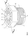
- a screw plug according to the invention for an outlet opening of a fluid-carrying housing part comprises a screw-in section 1 with a hollow cylindrical cross-section and circular in cross-section with an external thread 2, a contact flange 3 with an enlarged external diameter being formed on one end of the screw-in section 1 compared to the screw-in section.
- the screw-in section 1 and the contact flange 3 are advantageously produced as a one-piece plastic injection-molded part made from the same material, so that an integral component is formed.
- the screw-in section 1 is closed at one end with a base 4, and in the longitudinal direction, centrally through the contact flange 3 and the screw-in section 1, a recess 6 is formed as an internal engagement for a tool, which ends at the base 4 and, opposite the base 4, an insertion opening 7 for the engagement section of the tool.
- the contact flange 3 has a front contact surface 3 a, as seen in the screwing-in direction X, and an external engagement 8 for a tool on its outer circumference.
- This external attack 8 is shaped in particular as a polygon and preferably as a regular hexagon.
- the transition area between the contact flange 3 and the screw-in section 1 there is such a wall design of the screw plug that a tear-off area in the screwed-in state of the screw-in section 1 with the contact flange 3 in contact with a housing part due to a tear-off torque that is higher than a permissible tightening torque
- the screw-in direction is formed in the area of the end of the screw-in section 1 and behind the base 4, so that the flow of force within the locking screw does not run through the base 4 when it is torn off, and the recess 6 with the internal engagement has such a minimum engagement length L that a Loosening the locking screw by means of a tool inserted into the internal engagement 6 is possible.
- the minimum length of engagement L is advantageously dimensioned in accordance with DIN EN ISO 14579 of May 2002 and is in particular 3.6 mm long.
- the minimum length of engagement L is advantageously located between a bottom surface 9 of the bottom 4 of the contact flange 3 and the contact surface 3 a of the contact flange 3.
- the contact flange 3 has an inner recess 12, an outer circumferential wall 13 being formed which encloses an upper flange opening 14.
- a bottom surface 9 of the recess 12 of the contact flange 3 is formed opposite the flange opening 14.
- the bottom surface 9, viewed in longitudinal section, advantageously has a convexly curved shape directed into the recess 12. In particular, it is seen in the screw-in direction X.
- the deepest area of the bottom surface 9 below the insertion opening 7 of the recess 6 of the inner engagement and the rear, ie upper, area of the bottom surface 9 as seen in the insertion direction lies on the peripheral wall 13 above the insertion opening 7 of the recess 6 of the internal engagement.
- the base 4 is expediently shaped in such a way that it has a central base section 4a offset in the screw-in direction X in the direction of the free end of the screw-in section 1 and a base section 4b surrounding the base section 4a, which connects the central base section to a peripheral wall 1a of the screw-in section 1, and which advantageously runs perpendicular to the longitudinal center axis of the screw-in section 1.
- the bottom section 4a is, for example, convex in the direction of the free end of the screw-in section 1.
- the base section 4a can be arranged, for example, between the two ends of the screw-in section 1.
- the bottom section 4a has a width B between the recess 6, which expediently ends at the bottom section 4a, and its peripheral surface.
- the bottom section 4b is connected to the external attachment 8 of the contact flange 3 via a wall section 9a which has the bottom surface 9. As described above, this wall section 9a is expediently convex.
- a groove-shaped receiving section 18 for a circumferential seal 19 is present between the contact flange 3 and the screw-in section 1.
- This receiving section 18 preferably has an outer diameter in the area of its groove base that is smaller than a core diameter of the external thread 2 of the screw-in section 1.
- the circumferential seal 19 is designed in particular as an O-ring seal, the external diameter of which is greater than an external thread diameter of the external thread 2 .
- a radially protruding lip-like extension 20 is formed on the circumference of the end of the contact flange 3 pointing in the screwing direction X, as seen in the screwing-in direction X.
- this lip-like extension 20 is present between the respective corners of the polygon, for example an external hexagon.
- the extension 20 is designed in particular such that the outer diameter in the region of the extension 20 is equal to the outer diameter in the region of the opposite corners of the polygon, in particular the external hexagon. Because it is designed as an external hexagon, the screw-in section 1 according to the invention can be tightened with conventional wrenches.
- the stiffening webs 21 are arranged uniformly distributed around the circumference.
- the external attachment 8 is designed as a hexagon, for example, there are six, preferably twelve stiffening webs 21, of which six stiffening webs 21 each end in the corners of the hexagon and, in the embodiment with twelve stiffening webs 21, further stiffening webs 21 run centrally between the corners of the hexagon .
- the stiffening webs 21 end on the one hand with their upper edge 21a at the upper flange opening 14 and on the other hand at the insertion opening 7, so that the stiffening webs 21 extend obliquely inward with their upper edge 21a.
- a hollow-cylindrical extension 25 is formed on the connecting piece 16, in which the recess 6 for the internal engagement is located, counter to the screwing-in direction X.
- This extension 25 ends with its free end 26 preferably in the plane of the flange opening 14.
- the inner diameter of this extension 25 is adapted to an outer diameter of a tool shank, on which the engagement section is formed at the end, which fits into the recess 6 of the inner engagement.
- the stiffening webs 21 have such a height that their upper edge 21a runs transversely, preferably perpendicularly, to the longitudinal center axis of the locking screw and thus in the opening plane of the flange opening 14.
- the stiffening webs 21 are connected with their end facing away from the peripheral wall 13 to the connecting piece 16 and above this to the extension 25. This configuration of the screw plug according to the invention increases the rigidity of the contact flange 3.
- Fig. 6 shown that it can additionally be advantageous to form reinforcing webs 27 distributed around the circumference below the base 4 in the angular region between the base 4 and the screw-in section 1.
- These reinforcing webs 27 increase the overall rigidity of the screw plug.
- twelve reinforcing webs 27 arranged next to one another with the same spacing can be formed.
- the design corresponds to Figures 5 and 6th the embodiment according to Figures 1 to 4 as described above.
- the inventive design of the screw plug ensures that if the flange section 3 is torn off, the screw-in section 1 remains with the base 4 within the threaded hole of the housing part into which the screw plug is screwed, so that a defined exit of the fluid through the threads and in particular through a formed leakage path is given. It can be advantageous if in the circumferential surface of the Screw-in section 1 is formed in the area of the external thread 2 at least one axially running leakage path in the form of a leakage groove 23, whereby a controlled fluid outlet can be effected. It is advantageous if an existing leakage path begins at the front end of the screw-in section 1 in the screwing-in direction and its axial length corresponds at least to the height of two threads.
- the base 4 runs below the thread end, ie offset in relation to it in the screwing-in direction X, a secure closure of the housing opening is also ensured, the design according to the invention ensuring that the part of the locking screw according to the invention remaining after the tear-off over the inner engagement 6 can be unscrewed.
- the tightening torque is preferably 10 to 17 Nm and the tear-off torque is expediently 34 Nm.
- the loose torque is, for example, at least 2.5 Nm.
- the height of the contact flange 3 is, for example, 7 mm and the height of the extension 20 is, for example, 0.7 mm.
- a screw plug according to the invention is produced as an injection-molded part preferably from polymer material, in particular polyphthalamides (PPA), this being in particular a glass fiber reinforced material with in particular a 50% weight fraction of glass fiber material.
- PPA polyphthalamide
- the polyphthalamide (PPA) used is heat stabilized and has a high tensile strength.
Landscapes
- Engineering & Computer Science (AREA)
- General Engineering & Computer Science (AREA)
- Mechanical Engineering (AREA)
- Pressure Vessels And Lids Thereof (AREA)
- Lining And Supports For Tunnels (AREA)
- Surgical Instruments (AREA)
Claims (18)
- Bouchon fileté pour une ouverture de sortie de boîtiers conduisant des fluides comprenant une portion filetée (1) cylindrique circulaire avec un filetage extérieur (2) et une bride d'appui (3) à une extrémité de la portion filetée (1), ayant un diamètre extérieur agrandi par rapport à la portion filetée (1), la portion filetée (1) étant réalisée avec la bride d'appui (3) sous forme de pièce moulée par injection de plastique venue de matière et d'une seule pièce, et la portion filetée (1) étant fermée à une extrémité avec un fond (4), et un évidement (6), en tant que prise d'engagement intérieure pour un outil, s'étendant dans la direction longitudinale centralement à travers la bride d'appui (3) et la portion filetée (1), lequel évidement se termine au niveau du fond (4) et présente, à l'opposé du fond (4), une ouverture d'enfichage (7) pour l'outil, la bride d'appui (3) présentant, au niveau de sa périphérie extérieure, une prise d'engagement extérieure (8) pour un outil, un évidement intérieur périphérique (12) avec une ouverture de bride (14) étant réalisé entre la prise d'engagement extérieure (8) et la prise d'engagement intérieure (6), l'évidement intérieur (12) étant réalisé de telle sorte qu'une paroi périphérique extérieure (13) soit réalisée, laquelle entoure l'ouverture de bride supérieure (14), et une surface de fond intérieure (9) de la bride (3) étant réalisée dans la bride d'appui (3) entre la prise d'engagement intérieure (6) et la paroi périphérique (13) à l'opposé de l'ouverture de bride (14), et l'ouverture d'enfichage (7) de la prise d'engagement intérieure (6), vu dans la direction de vissage (X), étant disposée de manière décalée en arrière par rapport à la surface de fond (9) de la bride d'appui (3), de telle sorte qu'une portion de tubulure (16) faisant saillie depuis la surface de fond (9) dans la direction de l'ouverture de bride (14), se terminant en dessous de l'ouverture de bride (14) et comprenant l'ouverture d'enfichage (7) soit réalisée, et dans la région de transition entre la bride d'appui (3) et la portion filetée (1) étant prévue une réalisation de paroi telle que, dans le cas d'une rupture de la bride d'appui (3) dans l'état vissé de la portion filetée (1) et de l'appui de la bride d'appui (3), sous l'effet d'un couple de rupture accru par rapport au couple de vissage admis, appliqué au niveau de la prise d'engagement extérieure (8), vu dans la région de vissage (X), dans la région de à l'extrémité de la portion filetée (1) et derrière le fond (4), une région de rupture soit réalisée de telle sorte que le flux de forces à l'intérieur du bouchon fileté ne s'étende pas à travers le fond (4) lors de la rupture, une longueur d'engagement minimale (L) de l'évidement (6) pour la prise d'engagement intérieure étant prévue de telle manière qu'un desserrage du bouchon fileté au moyen d'un outil inséré dans la prise d'engagement intérieure (6) soit possible.
- Bouchon fileté selon la revendication 1, caractérisé en ce que la longueur d'engagement minimale (L) est dimensionnée conformément à la norme DIN EN ISO 14579 de mai 2002 et vaut en particulier 2,9 mm.
- Bouchon fileté selon la revendication 1 ou 2, caractérisé en ce que la longueur d'engagement minimale (L) est située entre la surface d'appui (3a) de la bride d'appui (3) et une surface de fond intérieure (11) de la prise d'engagement intérieure (6).
- Bouchon fileté selon l'une quelconque des revendications 1 à 3,
caractérisé en ce que le fond (4) est formé de telle sorte qu'il présente une portion de fond centrale (4a) décalée dans la direction de l'extrémité libre de la portion filetée (1) et une portion de fond (4b) entourant cette portion de fond centrale (4a), qui est connectée à une paroi périphérique (1a) de la portion filetée (1) et qui s'étend notamment perpendiculairement à l'axe médian longitudinal. - Bouchon fileté selon la revendication 4, caractérisé en ce que la portion de fond (4b) présente une largeur B et, sur une portion de paroi (9a) qui présente une surface de fond de courbure convexe (9) de l'évidement intérieur (12), est connectée à la région de la bride d'appui (3) présentant la prise d'engagement extérieure (8), qui possède une largeur radiale A, la largeur B étant de 20 % à 30 % supérieure à la largeur A.
- Bouchon fileté selon l'une quelconque des revendications 1 à 5,
caractérisé en ce que la longueur axiale de la prise d'engagement intérieure (6) est réalisée de telle sorte que, partant de son ouverture d'enfichage (7), sa surface de fond intérieure (11) soit disposée dans la région de l'extrémité de la portion filetée (1) de telle sorte que le filetage extérieur (2), vu dans la direction de vissage (X), se termine derrière la surface de fond intérieure (11). - Bouchon fileté selon l'une quelconque des revendications 1 à 6,
caractérisé en ce qu'une portion de réception en forme de rainure (18) pour un joint d'étanchéité périphérique (19) est réalisée entre la bride d'appui (3) et la portion filetée (1). - Bouchon fileté selon la revendication 7, caractérisé en ce que la portion de réception (18) présente, dans la région de son fond de rainure, un diamètre extérieur qui est inférieur à un diamètre de noyau du filetage extérieur (2) de la portion filetée (1).
- Bouchon fileté selon la revendication 7 ou 8, caractérisé en ce que le joint d'étanchéité périphérique (19) est réalisé sous forme de joint torique dont le diamètre extérieur est supérieur à un diamètre extérieur de filetage du filetage extérieur (2).
- Bouchon fileté selon l'une quelconque des revendications 1 à 9,
caractérisé en ce que la prise d'engagement extérieure (8) est réalisée sous forme de profil polygonal, en particulier sous forme de profil hexagonal régulier. - Bouchon fileté selon la revendication 10, caractérisé en ce qu'une saillie de type lèvre (20), faisant saillie radialement sur la périphérie au niveau de l'extrémité, tournée dans la direction de vissage (X), de la bride d'appui (3), est réalisée entre les coins du profil hexagonal, le diamètre de la saillie de type lèvre (20) étant de préférence identique au diamètre extérieur du profil hexagonal dans la région de ses coins opposés.
- Bouchon fileté selon l'une quelconque des revendications 1 à 11,
caractérisé en ce que la paroi périphérique extérieure (13) de la bride d'appui (3) et la portion de tubulure (16) de la prise d'engagement intérieure (6) sont connectées par des nervures de rigidification (21) qui sont façonnées au niveau de la surface de fond intérieure (9) et qui sont disposées de manière répartie uniformément sur la périphérie. - Bouchon fileté selon la revendication 12, caractérisé en ce que les nervures de rigidification (21) s'étendent avec leur arête supérieure libre (21a) dans le plan d'ouverture de l'ouverture de bride (14) et sont raccordées, avec leur extrémité opposée à la paroi périphérique (13), à une saillie cylindrique creuse (25) de la portion de tubulure (16).
- Bouchon fileté selon la revendication 13, caractérisé en ce que les nervures de rigidification (21) s'étendent avec leur arête supérieure (21a) dans le plan d'ouverture de l'ouverture de bride (14) perpendiculairement à l'axe médian longitudinal et la saillie (25) se termine également avec son extrémité libre (26) dans le plan d'ouverture de l'ouverture de bride (14) .
- Bouchon fileté selon l'une quelconque des revendications 12 à 14,
caractérisé en ce que dans le cas d'une réalisation de la prise d'engagement extérieure (8) en tant que profil hexagonal, douze nervures de rigidification (21) sont réalisées, dont à chaque fois six nervures de rigidification (21) se terminent dans les coins opposés du profil hexagonal et à chaque fois six nervures de rigidification (21) sont réalisées centralement entre les coins du profil hexagonal. - Bouchon fileté selon l'une quelconque des revendications 1 à 15, caractérisé en ce qu'au moins une rainure de fuite s'étendant axialement (23) est réalisée dans la portion filetée (1), au niveau de sa surface périphérique, dans la région du filetage extérieur (2).
- Bouchon fileté selon l'une quelconque des revendications 1 à 16,
caractérisé en ce que le rapport W : DK d'une largeur de clé W de la prise d'engagement extérieure (8) à un diamètre de noyau DK du filetage extérieur (2) vaut 1 : 0,85. - Bouchon fileté selon l'une quelconque des revendications 1 à 17,
caractérisé en ce que le bouchon fileté se compose de polyphthalamide (PPA) qui est notamment renforcé par des fibres de verre.
Applications Claiming Priority (2)
| Application Number | Priority Date | Filing Date | Title |
|---|---|---|---|
| DE102015116301.2A DE102015116301A1 (de) | 2015-09-25 | 2015-09-25 | "Verschlussschraube" |
| PCT/EP2016/069407 WO2017050490A1 (fr) | 2015-09-25 | 2016-08-16 | Bouchon fileté |
Publications (2)
| Publication Number | Publication Date |
|---|---|
| EP3353460A1 EP3353460A1 (fr) | 2018-08-01 |
| EP3353460B1 true EP3353460B1 (fr) | 2021-05-05 |
Family
ID=56802463
Family Applications (1)
| Application Number | Title | Priority Date | Filing Date |
|---|---|---|---|
| EP16757593.5A Active EP3353460B1 (fr) | 2015-09-25 | 2016-08-16 | Bouchon fileté |
Country Status (4)
| Country | Link |
|---|---|
| EP (1) | EP3353460B1 (fr) |
| CN (1) | CN108139012B (fr) |
| DE (1) | DE102015116301A1 (fr) |
| WO (1) | WO2017050490A1 (fr) |
Families Citing this family (7)
| Publication number | Priority date | Publication date | Assignee | Title |
|---|---|---|---|---|
| US20180292039A1 (en) * | 2017-04-06 | 2018-10-11 | Victor Kirilichin | Single Piece Expansion Sealing Plug |
| DE102017122301B3 (de) | 2017-09-26 | 2018-10-31 | Benteler Automobiltechnik Gmbh | Kraftstoffverteiler |
| CN108867801A (zh) * | 2018-07-17 | 2018-11-23 | 广东安格尔橡塑科技有限公司 | 一种密封式马桶法兰 |
| CN110822109B (zh) * | 2018-08-08 | 2023-05-23 | 浙江三花智能控制股份有限公司 | 阀装置 |
| CN110375128A (zh) * | 2019-07-01 | 2019-10-25 | 格力电器(合肥)有限公司 | 一种阀门及空调 |
| EP4094921A1 (fr) * | 2021-05-27 | 2022-11-30 | Stack Mold Plus UG (haftungsbeschränkt) | Dispositif avec joint d'étanchéité pour fermer des trous afin d'empêcher le passage d'un milieu |
| DE102021209796A1 (de) | 2021-09-06 | 2023-03-09 | Zf Friedrichshafen Ag | Verschlussschraube, insbesondere Verschlussschraube einer Austrittsöffnung eines Gehäuses |
Family Cites Families (16)
| Publication number | Priority date | Publication date | Assignee | Title |
|---|---|---|---|---|
| US3963322A (en) * | 1975-01-23 | 1976-06-15 | Ite Imperial Corporation | Torque controlling set screw for use with the cable of solderless connectors, or the like |
| US4518295A (en) * | 1983-06-20 | 1985-05-21 | Textron Inc. | Multi-part fastening nut, including jam nut |
| DE3431516A1 (de) * | 1984-08-28 | 1986-03-13 | Klöckner-Humboldt-Deutz AG, 5000 Köln | Gewindebuchse zur armierenden auskleidung einer oeffnung in einem werkstueck |
| ES2084567T1 (es) * | 1994-07-15 | 1996-05-16 | Limanin Establishment | Tornillo arrancable. |
| US6231286B1 (en) * | 1996-07-18 | 2001-05-15 | B & B Hardware, Inc. | Headed fastener with precisely calculated groove under head to accommodate O'ring sealing member as a self-sealing assembly |
| ATE199583T1 (de) * | 1998-08-18 | 2001-03-15 | Petri Gerhard Gmbh & Co Kg | Abreisskopfschraube |
| DE502007003243D1 (de) * | 2007-12-11 | 2010-05-06 | Nexans | Abscherschraube |
| DE102009018979A1 (de) * | 2009-04-25 | 2010-11-04 | Spang & Brands Gmbh | Brechverschluss zum Verstopfen eines Schlauchs |
| US8534428B2 (en) * | 2009-07-06 | 2013-09-17 | Shimano Inc. | One piece hydraulic disc brake caliper with one way plumbing |
| DE102012023594B3 (de) * | 2012-12-01 | 2014-02-27 | Obo Bettermann Gmbh & Co. Kg | Blindstopfen |
| US8911189B2 (en) * | 2013-02-26 | 2014-12-16 | Apical Industries, Inc. | Frangible fastener |
| DE102013101972A1 (de) | 2013-02-28 | 2014-08-28 | Linde Material Handling Gmbh | Hydraulikverschlussstopfen |
| WO2015104792A1 (fr) * | 2014-01-07 | 2015-07-16 | 株式会社小松製作所 | Structure pour fermer un trou pour un circuit hydraulique |
| CN203430948U (zh) * | 2013-08-14 | 2014-02-12 | 宁波恒力液压股份有限公司 | 一种切断式螺堵 |
| CN104214464A (zh) * | 2014-09-12 | 2014-12-17 | 江苏培达塑料有限公司 | 一种管道堵头 |
| CN204664097U (zh) * | 2015-06-01 | 2015-09-23 | 余姚市久源液压技术有限公司 | 一种液压油缸或管道用螺纹塞 |
-
2015
- 2015-09-25 DE DE102015116301.2A patent/DE102015116301A1/de not_active Withdrawn
-
2016
- 2016-08-16 WO PCT/EP2016/069407 patent/WO2017050490A1/fr not_active Ceased
- 2016-08-16 EP EP16757593.5A patent/EP3353460B1/fr active Active
- 2016-08-16 CN CN201680055829.9A patent/CN108139012B/zh active Active
Also Published As
| Publication number | Publication date |
|---|---|
| CN108139012B (zh) | 2020-08-21 |
| CN108139012A (zh) | 2018-06-08 |
| WO2017050490A1 (fr) | 2017-03-30 |
| DE102015116301A1 (de) | 2017-03-30 |
| EP3353460A1 (fr) | 2018-08-01 |
Similar Documents
| Publication | Publication Date | Title |
|---|---|---|
| EP3353460B1 (fr) | Bouchon fileté | |
| EP2049807B1 (fr) | Dispositif de fixation d'une pièce rapportée et d'une pièce de support à distance l'une de l'autre | |
| EP3025066B1 (fr) | Écrou à sertir en aveugle pour le raccordement de deux éléments | |
| EP2232089A1 (fr) | Insert fileté et pièce de véhicule | |
| EP3565976B1 (fr) | Dispositif de limitation de couple comportant trois brides | |
| EP1828623B1 (fr) | Dispositif pour fixer une piece a rajouter et un support espaces l'un de l'autre | |
| EP0986451B1 (fr) | Adaptateur pour tournevis | |
| EP2982874B1 (fr) | Bossage pour vis destine a la fixation d'un composant | |
| EP1919539A1 (fr) | Barre de prehension pour seringue assurant une meilleure protection contre la rupture | |
| EP3347607B1 (fr) | Joint à rotule équipé d'un capuchon de protection et bras de suspension à deux points équipé d'un tel joint à rotule | |
| DE202008000574U1 (de) | Verbindungseinrichtung | |
| DE102012107861A1 (de) | Befestigungsvorrichtung | |
| DE102016212547A1 (de) | Vorrichtung zum Festlegen an einem Bauteil und ein solches Bauteil | |
| EP3221598B1 (fr) | Corps déformable et système comprenant un corps déformable et une bague anti-fluage | |
| EP2064454B1 (fr) | Dispositif de fixation | |
| EP3587729B1 (fr) | Raccordement de deux membres de tige de forage d'une tige de forage destiné au forage du sol | |
| EP2308403B1 (fr) | Vis à os et système | |
| EP3626898B1 (fr) | Système de tubes profilés | |
| DE102010055808A1 (de) | Befestigungsvorrichtung | |
| DE102017116057A1 (de) | Befestigungsbaugruppe | |
| DE102015000490A1 (de) | Befestigungselement | |
| EP4299930B1 (fr) | Dispositif de liaison pour deux composants | |
| EP3537017A1 (fr) | Soupape | |
| DE202005003708U1 (de) | Bauteil mit Aussengewinde zum Einsetzen in ein Innengewinde | |
| DE2751233A1 (de) | Sicherungselement |
Legal Events
| Date | Code | Title | Description |
|---|---|---|---|
| STAA | Information on the status of an ep patent application or granted ep patent |
Free format text: STATUS: THE INTERNATIONAL PUBLICATION HAS BEEN MADE |
|
| PUAI | Public reference made under article 153(3) epc to a published international application that has entered the european phase |
Free format text: ORIGINAL CODE: 0009012 |
|
| STAA | Information on the status of an ep patent application or granted ep patent |
Free format text: STATUS: REQUEST FOR EXAMINATION WAS MADE |
|
| 17P | Request for examination filed |
Effective date: 20180219 |
|
| AK | Designated contracting states |
Kind code of ref document: A1 Designated state(s): AL AT BE BG CH CY CZ DE DK EE ES FI FR GB GR HR HU IE IS IT LI LT LU LV MC MK MT NL NO PL PT RO RS SE SI SK SM TR |
|
| AX | Request for extension of the european patent |
Extension state: BA ME |
|
| RIN1 | Information on inventor provided before grant (corrected) |
Inventor name: ROSOWSKI, EVELIN Inventor name: HAGEN, HARALD Inventor name: KLEHR, ADRIAN Inventor name: BRANDT, JOSEF |
|
| DAV | Request for validation of the european patent (deleted) | ||
| DAX | Request for extension of the european patent (deleted) | ||
| GRAP | Despatch of communication of intention to grant a patent |
Free format text: ORIGINAL CODE: EPIDOSNIGR1 |
|
| STAA | Information on the status of an ep patent application or granted ep patent |
Free format text: STATUS: GRANT OF PATENT IS INTENDED |
|
| INTG | Intention to grant announced |
Effective date: 20201214 |
|
| GRAS | Grant fee paid |
Free format text: ORIGINAL CODE: EPIDOSNIGR3 |
|
| GRAA | (expected) grant |
Free format text: ORIGINAL CODE: 0009210 |
|
| STAA | Information on the status of an ep patent application or granted ep patent |
Free format text: STATUS: THE PATENT HAS BEEN GRANTED |
|
| AK | Designated contracting states |
Kind code of ref document: B1 Designated state(s): AL AT BE BG CH CY CZ DE DK EE ES FI FR GB GR HR HU IE IS IT LI LT LU LV MC MK MT NL NO PL PT RO RS SE SI SK SM TR |
|
| REG | Reference to a national code |
Ref country code: GB Ref legal event code: FG4D Free format text: NOT ENGLISH |
|
| REG | Reference to a national code |
Ref country code: CH Ref legal event code: EP |
|
| REG | Reference to a national code |
Ref country code: AT Ref legal event code: REF Ref document number: 1390232 Country of ref document: AT Kind code of ref document: T Effective date: 20210515 |
|
| REG | Reference to a national code |
Ref country code: IE Ref legal event code: FG4D Free format text: LANGUAGE OF EP DOCUMENT: GERMAN |
|
| REG | Reference to a national code |
Ref country code: DE Ref legal event code: R096 Ref document number: 502016012996 Country of ref document: DE |
|
| REG | Reference to a national code |
Ref country code: LT Ref legal event code: MG9D |
|
| PG25 | Lapsed in a contracting state [announced via postgrant information from national office to epo] |
Ref country code: BG Free format text: LAPSE BECAUSE OF FAILURE TO SUBMIT A TRANSLATION OF THE DESCRIPTION OR TO PAY THE FEE WITHIN THE PRESCRIBED TIME-LIMIT Effective date: 20210805 Ref country code: HR Free format text: LAPSE BECAUSE OF FAILURE TO SUBMIT A TRANSLATION OF THE DESCRIPTION OR TO PAY THE FEE WITHIN THE PRESCRIBED TIME-LIMIT Effective date: 20210505 Ref country code: FI Free format text: LAPSE BECAUSE OF FAILURE TO SUBMIT A TRANSLATION OF THE DESCRIPTION OR TO PAY THE FEE WITHIN THE PRESCRIBED TIME-LIMIT Effective date: 20210505 Ref country code: LT Free format text: LAPSE BECAUSE OF FAILURE TO SUBMIT A TRANSLATION OF THE DESCRIPTION OR TO PAY THE FEE WITHIN THE PRESCRIBED TIME-LIMIT Effective date: 20210505 |
|
| PG25 | Lapsed in a contracting state [announced via postgrant information from national office to epo] |
Ref country code: NO Free format text: LAPSE BECAUSE OF FAILURE TO SUBMIT A TRANSLATION OF THE DESCRIPTION OR TO PAY THE FEE WITHIN THE PRESCRIBED TIME-LIMIT Effective date: 20210805 Ref country code: PL Free format text: LAPSE BECAUSE OF FAILURE TO SUBMIT A TRANSLATION OF THE DESCRIPTION OR TO PAY THE FEE WITHIN THE PRESCRIBED TIME-LIMIT Effective date: 20210505 Ref country code: PT Free format text: LAPSE BECAUSE OF FAILURE TO SUBMIT A TRANSLATION OF THE DESCRIPTION OR TO PAY THE FEE WITHIN THE PRESCRIBED TIME-LIMIT Effective date: 20210906 Ref country code: RS Free format text: LAPSE BECAUSE OF FAILURE TO SUBMIT A TRANSLATION OF THE DESCRIPTION OR TO PAY THE FEE WITHIN THE PRESCRIBED TIME-LIMIT Effective date: 20210505 Ref country code: SE Free format text: LAPSE BECAUSE OF FAILURE TO SUBMIT A TRANSLATION OF THE DESCRIPTION OR TO PAY THE FEE WITHIN THE PRESCRIBED TIME-LIMIT Effective date: 20210505 Ref country code: IS Free format text: LAPSE BECAUSE OF FAILURE TO SUBMIT A TRANSLATION OF THE DESCRIPTION OR TO PAY THE FEE WITHIN THE PRESCRIBED TIME-LIMIT Effective date: 20210905 Ref country code: LV Free format text: LAPSE BECAUSE OF FAILURE TO SUBMIT A TRANSLATION OF THE DESCRIPTION OR TO PAY THE FEE WITHIN THE PRESCRIBED TIME-LIMIT Effective date: 20210505 Ref country code: GR Free format text: LAPSE BECAUSE OF FAILURE TO SUBMIT A TRANSLATION OF THE DESCRIPTION OR TO PAY THE FEE WITHIN THE PRESCRIBED TIME-LIMIT Effective date: 20210806 |
|
| REG | Reference to a national code |
Ref country code: NL Ref legal event code: MP Effective date: 20210505 |
|
| PG25 | Lapsed in a contracting state [announced via postgrant information from national office to epo] |
Ref country code: NL Free format text: LAPSE BECAUSE OF FAILURE TO SUBMIT A TRANSLATION OF THE DESCRIPTION OR TO PAY THE FEE WITHIN THE PRESCRIBED TIME-LIMIT Effective date: 20210505 |
|
| PG25 | Lapsed in a contracting state [announced via postgrant information from national office to epo] |
Ref country code: SK Free format text: LAPSE BECAUSE OF FAILURE TO SUBMIT A TRANSLATION OF THE DESCRIPTION OR TO PAY THE FEE WITHIN THE PRESCRIBED TIME-LIMIT Effective date: 20210505 Ref country code: SM Free format text: LAPSE BECAUSE OF FAILURE TO SUBMIT A TRANSLATION OF THE DESCRIPTION OR TO PAY THE FEE WITHIN THE PRESCRIBED TIME-LIMIT Effective date: 20210505 Ref country code: CZ Free format text: LAPSE BECAUSE OF FAILURE TO SUBMIT A TRANSLATION OF THE DESCRIPTION OR TO PAY THE FEE WITHIN THE PRESCRIBED TIME-LIMIT Effective date: 20210505 Ref country code: EE Free format text: LAPSE BECAUSE OF FAILURE TO SUBMIT A TRANSLATION OF THE DESCRIPTION OR TO PAY THE FEE WITHIN THE PRESCRIBED TIME-LIMIT Effective date: 20210505 Ref country code: DK Free format text: LAPSE BECAUSE OF FAILURE TO SUBMIT A TRANSLATION OF THE DESCRIPTION OR TO PAY THE FEE WITHIN THE PRESCRIBED TIME-LIMIT Effective date: 20210505 Ref country code: RO Free format text: LAPSE BECAUSE OF FAILURE TO SUBMIT A TRANSLATION OF THE DESCRIPTION OR TO PAY THE FEE WITHIN THE PRESCRIBED TIME-LIMIT Effective date: 20210505 Ref country code: ES Free format text: LAPSE BECAUSE OF FAILURE TO SUBMIT A TRANSLATION OF THE DESCRIPTION OR TO PAY THE FEE WITHIN THE PRESCRIBED TIME-LIMIT Effective date: 20210505 |
|
| REG | Reference to a national code |
Ref country code: DE Ref legal event code: R097 Ref document number: 502016012996 Country of ref document: DE |
|
| PLBE | No opposition filed within time limit |
Free format text: ORIGINAL CODE: 0009261 |
|
| STAA | Information on the status of an ep patent application or granted ep patent |
Free format text: STATUS: NO OPPOSITION FILED WITHIN TIME LIMIT |
|
| REG | Reference to a national code |
Ref country code: CH Ref legal event code: PL |
|
| PG25 | Lapsed in a contracting state [announced via postgrant information from national office to epo] |
Ref country code: MC Free format text: LAPSE BECAUSE OF FAILURE TO SUBMIT A TRANSLATION OF THE DESCRIPTION OR TO PAY THE FEE WITHIN THE PRESCRIBED TIME-LIMIT Effective date: 20210505 |
|
| 26N | No opposition filed |
Effective date: 20220208 |
|
| REG | Reference to a national code |
Ref country code: BE Ref legal event code: MM Effective date: 20210831 |
|
| GBPC | Gb: european patent ceased through non-payment of renewal fee |
Effective date: 20210816 |
|
| PG25 | Lapsed in a contracting state [announced via postgrant information from national office to epo] |
Ref country code: LI Free format text: LAPSE BECAUSE OF NON-PAYMENT OF DUE FEES Effective date: 20210831 Ref country code: CH Free format text: LAPSE BECAUSE OF NON-PAYMENT OF DUE FEES Effective date: 20210831 |
|
| PG25 | Lapsed in a contracting state [announced via postgrant information from national office to epo] |
Ref country code: IS Free format text: LAPSE BECAUSE OF FAILURE TO SUBMIT A TRANSLATION OF THE DESCRIPTION OR TO PAY THE FEE WITHIN THE PRESCRIBED TIME-LIMIT Effective date: 20210905 Ref country code: LU Free format text: LAPSE BECAUSE OF NON-PAYMENT OF DUE FEES Effective date: 20210816 Ref country code: AL Free format text: LAPSE BECAUSE OF FAILURE TO SUBMIT A TRANSLATION OF THE DESCRIPTION OR TO PAY THE FEE WITHIN THE PRESCRIBED TIME-LIMIT Effective date: 20210505 |
|
| PG25 | Lapsed in a contracting state [announced via postgrant information from national office to epo] |
Ref country code: IT Free format text: LAPSE BECAUSE OF FAILURE TO SUBMIT A TRANSLATION OF THE DESCRIPTION OR TO PAY THE FEE WITHIN THE PRESCRIBED TIME-LIMIT Effective date: 20210505 Ref country code: IE Free format text: LAPSE BECAUSE OF NON-PAYMENT OF DUE FEES Effective date: 20210816 Ref country code: GB Free format text: LAPSE BECAUSE OF NON-PAYMENT OF DUE FEES Effective date: 20210816 Ref country code: BE Free format text: LAPSE BECAUSE OF NON-PAYMENT OF DUE FEES Effective date: 20210831 |
|
| REG | Reference to a national code |
Ref country code: AT Ref legal event code: MM01 Ref document number: 1390232 Country of ref document: AT Kind code of ref document: T Effective date: 20210816 |
|
| PG25 | Lapsed in a contracting state [announced via postgrant information from national office to epo] |
Ref country code: AT Free format text: LAPSE BECAUSE OF NON-PAYMENT OF DUE FEES Effective date: 20210816 |
|
| PG25 | Lapsed in a contracting state [announced via postgrant information from national office to epo] |
Ref country code: HU Free format text: LAPSE BECAUSE OF FAILURE TO SUBMIT A TRANSLATION OF THE DESCRIPTION OR TO PAY THE FEE WITHIN THE PRESCRIBED TIME-LIMIT; INVALID AB INITIO Effective date: 20160816 |
|
| PG25 | Lapsed in a contracting state [announced via postgrant information from national office to epo] |
Ref country code: CY Free format text: LAPSE BECAUSE OF FAILURE TO SUBMIT A TRANSLATION OF THE DESCRIPTION OR TO PAY THE FEE WITHIN THE PRESCRIBED TIME-LIMIT Effective date: 20210505 |
|
| P01 | Opt-out of the competence of the unified patent court (upc) registered |
Effective date: 20230526 |
|
| PG25 | Lapsed in a contracting state [announced via postgrant information from national office to epo] |
Ref country code: MK Free format text: LAPSE BECAUSE OF FAILURE TO SUBMIT A TRANSLATION OF THE DESCRIPTION OR TO PAY THE FEE WITHIN THE PRESCRIBED TIME-LIMIT Effective date: 20210505 |
|
| PG25 | Lapsed in a contracting state [announced via postgrant information from national office to epo] |
Ref country code: TR Free format text: LAPSE BECAUSE OF FAILURE TO SUBMIT A TRANSLATION OF THE DESCRIPTION OR TO PAY THE FEE WITHIN THE PRESCRIBED TIME-LIMIT Effective date: 20210505 |
|
| PG25 | Lapsed in a contracting state [announced via postgrant information from national office to epo] |
Ref country code: MT Free format text: LAPSE BECAUSE OF FAILURE TO SUBMIT A TRANSLATION OF THE DESCRIPTION OR TO PAY THE FEE WITHIN THE PRESCRIBED TIME-LIMIT Effective date: 20210505 |
|
| PGFP | Annual fee paid to national office [announced via postgrant information from national office to epo] |
Ref country code: FR Payment date: 20250728 Year of fee payment: 10 |
|
| PGFP | Annual fee paid to national office [announced via postgrant information from national office to epo] |
Ref country code: DE Payment date: 20251023 Year of fee payment: 10 |