EP3626898B1 - Système de tubes profilés - Google Patents
Système de tubes profilés Download PDFInfo
- Publication number
- EP3626898B1 EP3626898B1 EP19195374.4A EP19195374A EP3626898B1 EP 3626898 B1 EP3626898 B1 EP 3626898B1 EP 19195374 A EP19195374 A EP 19195374A EP 3626898 B1 EP3626898 B1 EP 3626898B1
- Authority
- EP
- European Patent Office
- Prior art keywords
- profile
- pipe
- half shell
- longitudinal
- connector
- Prior art date
- Legal status (The legal status is an assumption and is not a legal conclusion. Google has not performed a legal analysis and makes no representation as to the accuracy of the status listed.)
- Active
Links
Images

Classifications
-
- E—FIXED CONSTRUCTIONS
- E04—BUILDING
- E04B—GENERAL BUILDING CONSTRUCTIONS; WALLS, e.g. PARTITIONS; ROOFS; FLOORS; CEILINGS; INSULATION OR OTHER PROTECTION OF BUILDINGS
- E04B1/00—Constructions in general; Structures which are not restricted either to walls, e.g. partitions, or floors or ceilings or roofs
- E04B1/38—Connections for building structures in general
- E04B1/58—Connections for building structures in general of bar-shaped building elements
- E04B1/5825—Connections for building structures in general of bar-shaped building elements with a closed cross-section
- E04B1/5837—Connections for building structures in general of bar-shaped building elements with a closed cross-section of substantially circular form
- E04B1/585—Connections for building structures in general of bar-shaped building elements with a closed cross-section of substantially circular form with separate connection devices
-
- F—MECHANICAL ENGINEERING; LIGHTING; HEATING; WEAPONS; BLASTING
- F16—ENGINEERING ELEMENTS AND UNITS; GENERAL MEASURES FOR PRODUCING AND MAINTAINING EFFECTIVE FUNCTIONING OF MACHINES OR INSTALLATIONS; THERMAL INSULATION IN GENERAL
- F16B—DEVICES FOR FASTENING OR SECURING CONSTRUCTIONAL ELEMENTS OR MACHINE PARTS TOGETHER, e.g. NAILS, BOLTS, CIRCLIPS, CLAMPS, CLIPS OR WEDGES; JOINTS OR JOINTING
- F16B7/00—Connections of rods or tubes, e.g. of non-circular section, mutually, including resilient connections
- F16B7/04—Clamping or clipping connections
- F16B7/044—Clamping or clipping connections for rods or tubes being in angled relationship
- F16B7/048—Clamping or clipping connections for rods or tubes being in angled relationship for rods or for tubes without using the innerside thereof
- F16B7/0486—Clamping or clipping connections for rods or tubes being in angled relationship for rods or for tubes without using the innerside thereof forming an abutting connection of at least one tube
-
- E—FIXED CONSTRUCTIONS
- E04—BUILDING
- E04B—GENERAL BUILDING CONSTRUCTIONS; WALLS, e.g. PARTITIONS; ROOFS; FLOORS; CEILINGS; INSULATION OR OTHER PROTECTION OF BUILDINGS
- E04B1/00—Constructions in general; Structures which are not restricted either to walls, e.g. partitions, or floors or ceilings or roofs
- E04B1/18—Structures comprising elongated load-supporting parts, e.g. columns, girders, skeletons
- E04B1/24—Structures comprising elongated load-supporting parts, e.g. columns, girders, skeletons the supporting parts consisting of metal
- E04B1/2403—Connection details of the elongated load-supporting parts
- E04B2001/2421—Socket type connectors
-
- E—FIXED CONSTRUCTIONS
- E04—BUILDING
- E04B—GENERAL BUILDING CONSTRUCTIONS; WALLS, e.g. PARTITIONS; ROOFS; FLOORS; CEILINGS; INSULATION OR OTHER PROTECTION OF BUILDINGS
- E04B1/00—Constructions in general; Structures which are not restricted either to walls, e.g. partitions, or floors or ceilings or roofs
- E04B1/18—Structures comprising elongated load-supporting parts, e.g. columns, girders, skeletons
- E04B1/24—Structures comprising elongated load-supporting parts, e.g. columns, girders, skeletons the supporting parts consisting of metal
- E04B1/2403—Connection details of the elongated load-supporting parts
- E04B2001/2451—Connections between closed section profiles
-
- E—FIXED CONSTRUCTIONS
- E04—BUILDING
- E04B—GENERAL BUILDING CONSTRUCTIONS; WALLS, e.g. PARTITIONS; ROOFS; FLOORS; CEILINGS; INSULATION OR OTHER PROTECTION OF BUILDINGS
- E04B1/00—Constructions in general; Structures which are not restricted either to walls, e.g. partitions, or floors or ceilings or roofs
- E04B1/38—Connections for building structures in general
- E04B1/58—Connections for building structures in general of bar-shaped building elements
- E04B2001/5875—Connections for building structures in general of bar-shaped building elements using exterior clamping plates or shells
-
- E—FIXED CONSTRUCTIONS
- E04—BUILDING
- E04B—GENERAL BUILDING CONSTRUCTIONS; WALLS, e.g. PARTITIONS; ROOFS; FLOORS; CEILINGS; INSULATION OR OTHER PROTECTION OF BUILDINGS
- E04B1/00—Constructions in general; Structures which are not restricted either to walls, e.g. partitions, or floors or ceilings or roofs
- E04B1/38—Connections for building structures in general
- E04B1/58—Connections for building structures in general of bar-shaped building elements
- E04B2001/5887—Connections for building structures in general of bar-shaped building elements using connectors with sockets
Definitions
- the present invention relates to a profile tube system with at least one profile tube according to the preamble of claim 1.
- the invention also relates to a connector for such a profile tube system according to the preamble of claim 7.
- the individual profile tubes of such a profile tube system are usually connected to one another via connectors arranged on the longitudinal end, these connectors usually having two half-shells which can be screwed to one another via a screw connection.
- such connectors have a blind hole-like tube receptacle, so that such a connector can be slipped over a free longitudinal end of an associated profile tube and then firmly fixed on the profile tube by tightening the screw connection.
- a rotational fixation of a respective profile pipe in an associated pipe receptacle of a connector of a profile pipe system takes place via a separate component, usually a so-called tile cross, for which purpose the tile cross either in the pipe holder or in a Longitudinal end of the profile tube to be inserted into it must be fixed.
- the additional component designed as a tile cross requires additional manufacturing, storage, Logistics and assembly costs. If such a component is missing, for example such a tiled cross, the profile tube can be fixed in rotation in the blind-hole-shaped tube receptacle exclusively by means of the clamping forces exerted by the two half-shells of the connector.
- connectors of such profile tube systems are not suitable for the use of so-called double tube profiles with two parallel profile tubes that are connected to one another via a web, since this web would have to be led to the outside between the two half-shells of the connector which is not possible with conventional connectors.
- connectors known from the prior art can only be used for fastening double pipe profiles, provided that the web is removed from these in a longitudinal end area which is later arranged adjacent to the connectors.
- this requires additional manufacturing or manufacturing costs.
- the present invention is concerned with the problem of specifying an improved at least one alternative embodiment for a profile tube system of the generic type which overcomes the disadvantages known from the prior art.
- the present invention is based on the general idea of specifying a profile tube system, with at least one profile tube with at least two parallel longitudinal grooves / profile grooves and with a connector for attaching to the longitudinal end of the profile tube, with an integrated anti-rotation device being provided on the connector that does not require any additional assembly , there this is formed in one piece with a respective half-shell of the connector consisting of two half-shells.
- the connector of the profile pipe system according to the invention has a first half-shell and a second half-shell, which can be screwed together via a screw connection.
- the connector also has a blind-hole-like tube holder with a base, into which the profile tube can be inserted and in which the profile tube can be fixed via the two half-shells that are firmly screwed together.
- at least one inwardly protruding nose is arranged on an inner circumferential surface of the pipe receptacle of the first and / or second half-shell, which engages in a longitudinal groove of the profile pipe when the profile pipe system is installed and thereby prevents it from twisting or forms a rotation lock for it.
- the at least one nose is formed integrally, that is to say in one piece, with the respective half-shell and can therefore be produced together with it in a single and common production process. Subsequent assembly of such an anti-twist device is therefore not necessary.
- the at least one nose is preferably designed as a radially inwardly protruding collar extending over a certain circumferential area, an extension in the circumferential direction essentially corresponding to the extension of the associated longitudinal groove on the profile tube in the circumferential direction, so that when the profile tube system is installed, the at least one nose is free of play engages in the associated longitudinal groove and thereby forms a reliable and backlash-free anti-rotation device.
- a nose can be formed comparatively easily, for example by simply changing a production tool, on a half-shell which is otherwise already known.
- the at least one nose expediently has a predetermined breaking point and can be broken off by kinking, as a result of which the profile tube can be fixed in the tube receptacle of the connector independent of the angle of rotation.
- the nose is preferably designed so that it can easily be broken off or kinked with a screwdriver, with kinking and thus breaking off the nose by inserting a corresponding tool, for example a screwdriver, parallel to the longitudinal axis of the pipe receptacle on the inner surface becomes.
- the predetermined breaking point can be designed, for example, as a cross-sectional thinning, whereby a force can be applied by the at least one nose in the circumferential direction and serves to prevent the profile tube from rotating in the tube receptacle , is comparatively large, while a force required to kink the at least one nose is significantly smaller.
- two such noses can also be provided per half-shell, so that in the case of a profile tube having four longitudinal grooves, each longitudinal groove is occupied by an associated nose in the assembled state.
- both a rotational fixation of the profile tube in the tube receptacle and a simple kinking of the respective noses can fix the profile tube in the tube independent of the angle of rotation Tube recording can be achieved.
- the same half-shell can be used for both embodiments, which may have to be adapted accordingly by kinking the noses.
- each half-shell has a groove on a first half-shell longitudinal edge and a tongue designed to complement it on a second half-shell longitudinal edge, so that in the assembled state the two half-shells are connected to one another at their half-shell longitudinal edges via a partially closed tongue and groove connection.
- a partially closed tongue and groove connection In the area of the pipe receptacle, there is no groove or tongue on the longitudinal edges of the half-shell, so that the two longitudinal edges of the half-shell are spaced apart from one another in this area and form a slot.
- the tongue and groove connection offers the great advantage of a clear assembly position, so that a correct assembly position is enforced when the connector consisting of the two half-shells is assembled.
- the tongue-and-groove connection or the slot between the two longitudinal edges of the half-shell allows a so-called double-tube profile with two parallel profile tubes that are connected to one another via a web to be easily and reliably connected to another profile tube .
- a connector is attached to two adjacent longitudinal ends of the profile tubes of the double tube profile in such a way that the web of the double tube profile is guided through the slot between the half-shells. Due to the slot remaining between the two half-shell longitudinal edges, such a connector can easily be used both with normal profile tubes and with double-tube profiles with two profile tubes and a web arranged in between.
- the first and second half-shells are designed as identical parts.
- a design of the two half-shells as identical parts reduces the tool costs and thus also the unit costs and thus enables not only a high quality but also a very cost-effective design of the connector.
- each half-shell has a through opening for the screw connection running transversely to the longitudinal direction, with a hexagonal receptacle for a nut of the screw connection being provided in each half-shell, accessible from a half-shell back.
- Each half-shell expediently has an edge oriented transversely to the longitudinal direction with an undercut contour at a longitudinal end facing away from the tube receptacle, so that the connector can engage with its two edges in associated profile grooves of a further profile tube and can be fixed to the further profile tube in the assembled state.
- profile tubes For example round tubes, each have longitudinal grooves, whereby a connector can engage with its two edges in two adjacent longitudinal grooves and engage behind them, with the two edges being pressed against the two groove edges by tightening the screw connection and thereby fixing the connector to the further profile tube can be done.
- the edge and the undercut contour together form a hook contour.
- the profile tube and / or the half-shells are / is made of aluminum.
- the design of the profile tube as an extruded profile enables the same to be inexpensive and at the same time weight-optimized.
- the half-shells and thus the connector can also be made from aluminum, although it is of course also theoretically conceivable to make the connector and thus the half-shells from plastic.
- a connector for a profile tube system such a connector having a first half-shell and a second half-shell which can be screwed together via a screw connection.
- a connector has a blind hole-like tube receptacle with a base, with at least one inwardly protruding nose being arranged on an inner circumferential surface of the tube receptacle of the first and / or second half-shell.
- a simple and at the same time effective anti-rotation device can be created via such an inwardly protruding nose which, when the connector is mounted on a profile tube, engages in an associated longitudinal groove of the profile tube.
- the at least one nose per half-shell is usually designed in one piece with the respective half-shell and is produced together with it, so that the anti-rotation device is provided by a simple adaptation of a die-casting tool, provided the half-shell is made of aluminum, for example is formed, is feasible.
- a nose of this type separate components previously used for anti-twist protection, such as a tile cross, can be dispensed with, which not only eliminates the manufacturing costs for the additional component, but also the storage and logistics costs previously required for this.
- there are also no assembly costs since there is no separate assembly of the anti-twist device through the nose provided according to the invention on the respective half-shell.
- the nose expediently has a predetermined breaking point and can be broken off by kinking. If, for example, no anti-rotation device is desired, the nose representing the anti-rotation device can simply be bent, for example by means of a screwdriver, and thereby broken off.
- the respective nose preferably extends linearly in the circumferential direction and to such an extent that it can be inserted into an associated longitudinal groove of the profile tube with as little play as possible.
- the nose Due to the nose extending linearly in the circumferential direction, it can be bent over or broken off comparatively easily by a force acting on it in the axial direction, for example by inserting a screwdriver into the blind hole-like tube receptacle, since the nose, for example in the transition to the inner lateral surface of the associated half-shell, for example has a reduction in cross section. Such a cross-sectional reduction can also be implemented comparatively easily by means of a corresponding die-casting tool.
- Each half-shell expediently has a groove on a first half-shell longitudinal edge and a complementary tongue on a second half-shell longitudinal edge, so that the two half-shells in the assembled state are connected to one another at their half-shell longitudinal edges via an at least partially closed tongue-and-groove connection.
- the connector according to the invention can be used comparatively easily both with simple profile tubes and with double-tube profiles with a web arranged in between, since the web can be guided through the slots of the two adjacent connectors.
- the first and second half-shells of the connector are expediently designed as identical parts. In this way, the tool costs and thus also the unit costs can be reduced and the connector can be manufactured inexpensively.
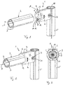
- a profile tube system 1 according to the invention has at least one profile tube 2 with at least two parallel longitudinal grooves 3.
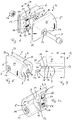
- the profile pipe system 1 according to the invention has a connector 4 (see also the Figures 7 to 10 ) for attachment to the profile tube 2 on the longitudinal end side, the connector 4 having a first half-shell 5 and a second half-shell 6, which can be screwed together via a screw connection 7.
- the connector 4 has a blind hole-like tube holder 8 with a base 9, into which the profile tube 2 can be inserted, preferably up to the base 9, and in which the profile tube 2 can be fixed via the two half-shells 5, 6 that are firmly screwed together.
- At least one radially inwardly protruding nose 11 is arranged on an inner surface of the tube receptacle 8 of the first and / or second half-shell 5, 6 in the assembled state (compare in particular the Figures 3 and 4th ) engages in a longitudinal groove 3 of the profile tube 2 and thereby forms an anti-twist device for this.
- the nose 11 preferably has a trapezoidal shape and extends in the circumferential direction of the inner circumferential surface of the pipe receptacle 8 of the half-shell 5, 6 (compare FIGS Figures 8 and 10 ) and has a significantly smaller thickness in the axial direction (along the longitudinal axis 10) than in the circumferential direction.
- the trapezoidal design of the nose 11 makes it easier to insert the same into an associated longitudinal groove 3 of the profile tube 2.
- the nose can 11 by means of a tool, for example a screwdriver, also comparatively easily kink and break off, which makes it comparatively easy to mount a corresponding profile tube 2 in the tube holder 8 independent of the angle of rotation.
- the at least one nose 11 can have a predetermined breaking point which simplifies the kinking and ultimately also the breaking off of the nose 11.
- the nose 11 is also arranged in a recess 12 arranged on the inner circumferential surface of the tube holder 8, so that if the nose 11 breaks off and the anti-twist device is removed, no material protrudes beyond the inner surface of the tube holder 8 and thereby under certain circumstances a rotation of the profile tube 2 received in the tube receptacle 8 is prevented. It is of course clear that the nose 11, in spite of its arrangement in the recess 12, protrudes inwardly beyond the inner surface of the tube receptacle 8 when it is not broken off.
- the predetermined breaking point of the nose 11 lies in the recess 12, so that after the nose 11 is broken off, a half-shell-side fracture surface lies in the recess 12, i.e. radially outside the inner surface of the pipe receptacle 8 and therefore no contact with a later mounted in the pipe receptacle 8 Profile tube 2 has.
- the recess 12 also offers the advantage of an abutment for levering out / breaking off the nose 11.
- the recess 12 forms, for example, a contact / support surface over which a screwdriver, for example, can be levered.
- the nose 11 With the nose 11 according to the invention, a comparatively simple, inexpensive and at the same time easy-to-assemble anti-rotation device can be achieved, since the nose 11 is preferably designed in one piece with the respective half-shell 5, 6, so that only one Manufacturing tool, for example a die-casting tool, if the half-shell 5, 6 is made of aluminum, must be adapted.
- additional components such as, for example, a tile cross, which had to be mounted in an associated recess 13 on the bottom 9 of the pipe receptacle 8 and / or inserted into the profile pipe 2.
- a tile cross can of course also be provided in the connector 4 according to the invention. However, it is no longer necessary to prevent rotation.
- each half-shell 5, 6 has a groove 15 on a first half-shell longitudinal edge 14 and a tongue 17 formed complementary to groove 11 on a second half-shell longitudinal edge 16, so that the two half-shells 5, 6 in the assembled state at their half-shell longitudinal edges 14, 16 are each connected to one another via an at least partially closed tongue and groove connection and are also aligned / positioned to one another via these.
- each half-shell 5, 6 has an in particular cuboid-shaped positioning element 22 as well as a likewise cuboid-shaped positioning opening 23 which, when the half-shells 5, 6 are connected to one another, interact with the positioning openings 23 or positioning elements 22 of the opposite half-shell 6, 5, thereby clearly fixing the position between force both half-shells 5, 6.
- Each half-shell 5, 6 also has a through-opening 24 for the screw connection 7 running transversely to the longitudinal direction (axial direction of the pipe receptacle 8), a receptacle 26 for a nut 27 of the screw connection 7 being provided in each half-shell 5, 6, accessible from a half-shell back 25 , in which the nut 27 can be received in a form-fitting manner (compare in particular the Figure 7 ).
- each half-shell 5, 6 has, at its longitudinal end facing away from the tube receptacle 8, an edge 28 oriented transversely to the longitudinal direction 10 with an undercut contour 29, so that the connector 4, in the assembled state, with its two edges 20 in associated longitudinal grooves / profile grooves 3 of a further profile tube 2 'can intervene and can be fixed on the further profile tube 2'.
- the undercut contours 29 preferably have a rounded base 30, which is designed to be complementary to a round outer contour of the further profile tube 2 'and thus preferably rests flat against it.
- a rotation lock of a profile tube 2 in the connector 4 by means of the nose 11 according to the invention can thus be implemented in a comparatively simple manner, with the profile tubes 2 being fixed in the connector 4 independently of the angle of rotation due to the preferably easy breakability of the nose 11 is possible.
- the connectors 4 according to the invention can also be used to assemble a double tube profile 20 comparatively easily without further processing.
Landscapes
- Engineering & Computer Science (AREA)
- General Engineering & Computer Science (AREA)
- Architecture (AREA)
- Mechanical Engineering (AREA)
- Physics & Mathematics (AREA)
- Electromagnetism (AREA)
- Civil Engineering (AREA)
- Structural Engineering (AREA)
- Quick-Acting Or Multi-Walled Pipe Joints (AREA)
- Mutual Connection Of Rods And Tubes (AREA)
Claims (11)
- Système de tubes profilés (1)- avec au moins un tube profilé (2) avec au moins deux rainures longitudinales (3) parallèles,- avec un connecteur (4) pour le montage côté extrémité longitudinale sur le tube profilé (2), qui présente une première demi-coque (5) et une deuxième demi-coque (6), qui peuvent être vissées l'une avec l'autre par le biais d'un raccord vissé (7),- dans lequel le connecteur (4) présente un logement de tube (8) de type trou borgne avec un fond (9), dans lequel le tube profilé (2) est enfichable et dans lequel le tube profilé (2) peut être fixé par le biais de deux demi-coques (5, 6) vissées solidement l'une à l'autre,- dans lequel au moins un nez (11) en saillie vers l'intérieur, qui vient en prise à l'état monté dans une rainure longitudinale (3) du tube profilé (2) et forme une sécurité anti-rotation pour celui-ci, est agencé au niveau d'une surface d'enveloppe intérieure du logement de tube (8) de la première et/ou deuxième demi-coque (5, 6),
caractérisé en ce- que l'au moins un nez (11) présente un point de rupture théorique et est détachable par pliage, ce par quoi une fixation indépendante de l'angle de rotation du tube profilé (2) est réalisable dans le logement de tube (8),- que le nez (11) est agencé dans un évidement (12) agencé au niveau de la surface d'enveloppe intérieure du logement de tube (8). - Système de tubes profilés selon la revendication 1,
caractérisé en ce- que chaque demi-coque (5, 6) présente au niveau d'un premier bord longitudinal de demi-coque (14) une rainure (15) et au niveau d'un deuxième bord longitudinal de demi-coque (16) une languette (17) réalisée de manière complémentaire à celle-ci, de sorte que les deux demi-coques (5, 6) sont reliées l'une à l'autre à l'état monté au niveau de leurs bords longitudinaux de demi-coque (14, 16) respectivement par le biais d'un raccord rainure-languette partiellement fermé,- que dans la zone du logement de tube (8) au niveau du premier bord longitudinal de demi-coque (14) aucune rainure (15) n'est prévue et au niveau du deuxième bord longitudinal de demi-coque (16) aucune languette (17) n'est prévue, de sorte que les deux bords longitudinaux de demi-coque (14, 16) sont espacés l'un de l'autre dans cette zone (18) et forment une fente (19). - Système de tubes profilés selon la revendication 1 ou 2,
caractérisé en ce
qu'un profil de double tube (20) avec deux tubes profilés (2) parallèles est prévu, qui sont reliés l'un à l'autre par le biais d'une entretoise (21), dans lequel respectivement un connecteur (4) est enfiché sur deux extrémités longitudinales adjacentes des tubes profilés (2) du profil de double tube (20) de sorte que l'entretoise (21) du profil de double tube (20) est guidée à travers la fente (19) entre les demi-coques (5, 6). - Système de tubes profilés selon l'une quelconque des revendications précédentes,
caractérisé en ce- que chaque demi-coque (5, 6) présente une ouverture de passage (24) s'étendant transversalement à la direction longitudinale pour le raccord vissé (7), dans lequel un logement (26) accessible depuis un dos de demi-coque (25) pour un écrou (27) du raccord vissé (7), dans lequel l'écrou (27) peut être reçu par complémentarité de forme, est prévu dans chaque demi-coque (5, 6) et/ou- que la première et la deuxième demi-coque (5, 6) sont réalisées en tant que pièces identiques. - Système de tubes profilés selon l'une quelconque des revendications précédentes,
caractérisé en ce
que chaque demi-coque (5, 6) présente au niveau de son extrémité longitudinale opposée au logement de tube (8), une arête (28) orientée transversalement à la direction longitudinale avec un contour de contre-dépouille (29), de sorte que le connecteur (4) peut venir en prise à l'état monté avec ses deux arêtes (28) dans des rainures longitudinales (3) correspondantes d'un autre tube profilé (2') et peut être fixé en outre sur l'autre tube profilé (2'). - Système de tubes profilés selon la revendication 5,
caractérisé en ce
que les contours de contre-dépouille (29) se transforment en un fond (30) arrondi, qui est réalisé de manière complémentaire à un contour extérieur rond de l'autre tube profilé (2'). - Connecteur (4) pour un système de tubes profilés (1) selon la revendication 1- avec une première demi-coque (5) et une deuxième demi-coque (6), qui peuvent être vissées l'une à l'autre par le biais d'un raccord vissé (7),- avec un logement de tube (8) de type trou borgne avec un fond (9),
caractérisé en ce- qu'au moins un nez (11) en saillie vers l'intérieur, qui présente un point de rupture théorique et est détachable par pliage, est agencé au niveau d'une surface d'enveloppe intérieure du logement de tube (8) de la première et/ou deuxième demi-coque (5, 6),- que le nez (11) est agencé dans un évidement (12) agencé au niveau de la surface d'enveloppe intérieure du logement de tube (8). - Connecteur selon la revendication 7,
caractérisé en ce- que chaque demi-coque (5, 6) présente au niveau d'un premier bord longitudinal de demi-coque (14) une rainure (15) et au niveau d'un deuxième bord longitudinal de demi-coque (16) une languette (17) réalisée de manière complémentaire à celle-ci, de sorte que les deux demi-coques (5, 6) sont reliées l'une à l'autre à l'état monté au niveau de leurs bords longitudinaux de demi-coque (14, 16) respectivement par le biais d'un raccord rainure-languette partiellement fermé.- que dans la zone (18) du logement de tube (8) au niveau du premier bord longitudinal de demi-coque (14) aucune rainure (15) n'est prévue et au niveau du deuxième bord longitudinal de demi-coque (16) aucune languette (17) n'est prévue, de sorte que les deux bords longitudinaux de demi-coque (14, 16) sont espacés l'un de l'autre dans cette zone (18) et forment une fente (19). - Connecteur selon l'une quelconque des revendications 7 ou 8,
caractérisé en ce
que la première et la deuxième demi-coque (5, 6) sont réalisées en tant que pièces identiques. - Connecteur selon l'une quelconque des revendications 7 à 9,
caractérisé en ce
que chaque demi-coque (5, 6) présente au niveau de son extrémité longitudinale opposée au logement de tube (8), une arête (28) orientée transversalement à la direction longitudinale avec un contour de contre-dépouille (29). - Connecteur selon la revendication 10,
caractérisé en ce
que les contours de contre-dépouille (29) se transforment en un fond (30) arrondi.
Applications Claiming Priority (1)
| Application Number | Priority Date | Filing Date | Title |
|---|---|---|---|
| DE102018216086.4A DE102018216086A1 (de) | 2018-09-20 | 2018-09-20 | Profilrohrsystem |
Publications (2)
| Publication Number | Publication Date |
|---|---|
| EP3626898A1 EP3626898A1 (fr) | 2020-03-25 |
| EP3626898B1 true EP3626898B1 (fr) | 2020-12-09 |
Family
ID=67902314
Family Applications (1)
| Application Number | Title | Priority Date | Filing Date |
|---|---|---|---|
| EP19195374.4A Active EP3626898B1 (fr) | 2018-09-20 | 2019-09-04 | Système de tubes profilés |
Country Status (2)
| Country | Link |
|---|---|
| EP (1) | EP3626898B1 (fr) |
| DE (1) | DE102018216086A1 (fr) |
Families Citing this family (1)
| Publication number | Priority date | Publication date | Assignee | Title |
|---|---|---|---|---|
| CN115071508B (zh) * | 2022-07-11 | 2023-03-28 | 宝鸡保德利电气设备有限责任公司 | 一种组装式腕臂支撑定位装置 |
Citations (5)
| Publication number | Priority date | Publication date | Assignee | Title |
|---|---|---|---|---|
| JP2003172323A (ja) | 2001-12-03 | 2003-06-20 | Sus Corp | プロファイルコネクタおよびプロファイルの接合構造 |
| DE202005007822U1 (de) | 2005-04-01 | 2005-10-13 | Ipeg Gmbh - Ingenieurdienstleistungen | Adaptive Basistruktur zur Aufnahme von handelsüblichen Möbelverbindern |
| EP1617087A1 (fr) | 2004-07-13 | 2006-01-18 | NORGREN Automotive GmbH | Dispositif de support |
| DE202009008687U1 (de) | 2009-06-18 | 2010-11-04 | Rixen, Wolfgang, Dipl.-Ing. | Profilstabverbindungssystem |
| DE102009042238A1 (de) | 2009-09-18 | 2011-04-07 | Robert Bosch Gmbh | Klemmbauteil mit einer Schneide zur Herstellung einer elektrisch leitenden Verbindung |
Family Cites Families (1)
| Publication number | Priority date | Publication date | Assignee | Title |
|---|---|---|---|---|
| DE10017897C2 (de) * | 2000-04-11 | 2002-09-26 | Tuenkers Maschinenbau Gmbh | Gerüstsystem, zur Verwendung im Karosseriebau der Kfz-Industrie, zum Anordnen von Kniehebelspannvorrichtungen, Saugvorrichtungen, Zentrierdornen, Sensoren, Schweißvorrichtungen, Clinchvorrichtungen, Nietvorrichtungen o. dgl., z. B. zur Verbindung mit einem Roboterarm oder dergleichen |
-
2018
- 2018-09-20 DE DE102018216086.4A patent/DE102018216086A1/de not_active Withdrawn
-
2019
- 2019-09-04 EP EP19195374.4A patent/EP3626898B1/fr active Active
Patent Citations (5)
| Publication number | Priority date | Publication date | Assignee | Title |
|---|---|---|---|---|
| JP2003172323A (ja) | 2001-12-03 | 2003-06-20 | Sus Corp | プロファイルコネクタおよびプロファイルの接合構造 |
| EP1617087A1 (fr) | 2004-07-13 | 2006-01-18 | NORGREN Automotive GmbH | Dispositif de support |
| DE202005007822U1 (de) | 2005-04-01 | 2005-10-13 | Ipeg Gmbh - Ingenieurdienstleistungen | Adaptive Basistruktur zur Aufnahme von handelsüblichen Möbelverbindern |
| DE202009008687U1 (de) | 2009-06-18 | 2010-11-04 | Rixen, Wolfgang, Dipl.-Ing. | Profilstabverbindungssystem |
| DE102009042238A1 (de) | 2009-09-18 | 2011-04-07 | Robert Bosch Gmbh | Klemmbauteil mit einer Schneide zur Herstellung einer elektrisch leitenden Verbindung |
Non-Patent Citations (9)
| Title |
|---|
| ANONYMOUS ET AL: "Mechanik-Grundelemente", KATALOG MGE 13.0, 6 September 2012 (2012-09-06), XP055427109, Retrieved from the Internet <URL:http://www.betz.cz/download_soubory/Katalog_MGE_13.0_DE.pdf> [retrieved on 20171121] * |
| ANONYMOUS: "Aluminium-Selbstbauelemente", BOSCH FLEXIBLE AUTOMATION, March 1996 (1996-03-01), pages 1 - 3, XP055699981 |
| ANONYMOUS: "ALU-Profil-Systeme", MSI (MONTAGE-SYSTEME-INDUSTRIEAUSRÜSTUNG), 2009, pages 1 - 2, XP055699985 |
| ANONYMOUS: "Die Baureihe D30-das Lean Production System 2.1", ITEM INDUSTRIETECHNIK, January 2014 (2014-01-01), pages 37, XP055700005 |
| ANONYMOUS: "Innovationen mit System. Neuheiten Herbst 2011", ITEM INDUSTRIETECHNIK, 1 September 2011 (2011-09-01), pages 1 - 3, XP055699999 |
| ANONYMOUS: "Katalog Kompatible Profilreihen und System-Engineering1", FM SYSTEME, vol. 4, no. 02, 1 August 2014 (2014-08-01), pages - 3, XP055699988 |
| ANONYMOUS: "MB Systembaukasten (MB8) Der Gesamtkatalog", ITEM INDUSTRIETECHNIK, 1 March 2012 (2012-03-01), pages 114, XP055700007 |
| ANONYMOUS: "MB Systembaukasten (MB9) Der Gesamtkatalog", ITEM VERBINDUNGSTECHNIK, 1 October 2016 (2016-10-01), pages 95 - 101, XP055699996 |
| ANONYMOUS: "Mechanik-Grundelemente 13.2", REXROTH BOSCH GROUP, August 2017 (2017-08-01), pages 1 - 6, XP055699976 |
Also Published As
| Publication number | Publication date |
|---|---|
| EP3626898A1 (fr) | 2020-03-25 |
| DE102018216086A1 (de) | 2020-03-26 |
Similar Documents
| Publication | Publication Date | Title |
|---|---|---|
| EP3717786B1 (fr) | Dispositif de compensation de tolérance avec sécurité par serrage | |
| EP2318723B1 (fr) | Agencement de fixation avec compensation des tolerances | |
| EP2757299B1 (fr) | Dispositif de serrage de tuyau | |
| EP2481939B1 (fr) | collier de serrage | |
| EP2459425B1 (fr) | Ensemble constitué d'un réservoir de compensation et d'un maître-cylindre pour un système de freinage hydraulique d'un véhicule à moteur | |
| EP3004702B1 (fr) | Combination d'un boîtier et d'une soupape | |
| EP4239233B1 (fr) | Demi-écrou et procédé d'assemblage d'un demi-écrou | |
| EP3353460B1 (fr) | Bouchon fileté | |
| DE10315690B4 (de) | Befestigungsvorrichtung für eine Anhängevorrichtung an einem Längsträger eines Kraftfahrzeuges | |
| EP2019765B1 (fr) | Dispositif et procédé pour fixer un moteur d'essuie-glace sur une tringlerie d'essuie-glace | |
| EP1828623B1 (fr) | Dispositif pour fixer une piece a rajouter et un support espaces l'un de l'autre | |
| DE102021100676A1 (de) | Halteelement zum Befestigen eines Anbauteils | |
| EP2775187B1 (fr) | Dispositif de raccord pour tuyau souple | |
| EP3581811B1 (fr) | Système de fixation d'un premier composant sur un second composant | |
| EP3105483B1 (fr) | Bride de fixation | |
| EP3626898B1 (fr) | Système de tubes profilés | |
| DE10200376A1 (de) | Befestigungsvorrichtung | |
| WO2008000319A1 (fr) | Dispositif de fixation de ferrures sur des profilés creux | |
| EP2568207B1 (fr) | Raccordement de tuyau | |
| WO2018077665A1 (fr) | Système de fixation | |
| EP1713991B1 (fr) | Paire de poignées de porte avec une fixation de serrage de poignée de porte | |
| DE102023207479A1 (de) | Vorrichtung zum Ausgleichen von Toleranzen | |
| EP2102038B1 (fr) | Ensemble boîtier d'un système essuie-glace à assemblage vissé | |
| EP3366851B1 (fr) | Ensemble soupape de remplissage universel | |
| EP4090854B1 (fr) | Manchon de contre-palier |
Legal Events
| Date | Code | Title | Description |
|---|---|---|---|
| PUAI | Public reference made under article 153(3) epc to a published international application that has entered the european phase |
Free format text: ORIGINAL CODE: 0009012 |
|
| STAA | Information on the status of an ep patent application or granted ep patent |
Free format text: STATUS: THE APPLICATION HAS BEEN PUBLISHED |
|
| AK | Designated contracting states |
Kind code of ref document: A1 Designated state(s): AL AT BE BG CH CY CZ DE DK EE ES FI FR GB GR HR HU IE IS IT LI LT LU LV MC MK MT NL NO PL PT RO RS SE SI SK SM TR |
|
| AX | Request for extension of the european patent |
Extension state: BA ME |
|
| STAA | Information on the status of an ep patent application or granted ep patent |
Free format text: STATUS: REQUEST FOR EXAMINATION WAS MADE |
|
| TPAC | Observations filed by third parties |
Free format text: ORIGINAL CODE: EPIDOSNTIPA |
|
| 17P | Request for examination filed |
Effective date: 20200423 |
|
| RBV | Designated contracting states (corrected) |
Designated state(s): AL AT BE BG CH CY CZ DE DK EE ES FI FR GB GR HR HU IE IS IT LI LT LU LV MC MK MT NL NO PL PT RO RS SE SI SK SM TR |
|
| RIC1 | Information provided on ipc code assigned before grant |
Ipc: E04B 1/58 20060101AFI20200507BHEP Ipc: E04B 1/24 20060101ALN20200507BHEP Ipc: F16B 7/04 20060101ALI20200507BHEP |
|
| RIC1 | Information provided on ipc code assigned before grant |
Ipc: E04B 1/24 20060101ALN20200512BHEP Ipc: E04B 1/58 20060101AFI20200512BHEP Ipc: F16B 7/04 20060101ALI20200512BHEP |
|
| GRAP | Despatch of communication of intention to grant a patent |
Free format text: ORIGINAL CODE: EPIDOSNIGR1 |
|
| STAA | Information on the status of an ep patent application or granted ep patent |
Free format text: STATUS: GRANT OF PATENT IS INTENDED |
|
| INTG | Intention to grant announced |
Effective date: 20200630 |
|
| GRAS | Grant fee paid |
Free format text: ORIGINAL CODE: EPIDOSNIGR3 |
|
| GRAA | (expected) grant |
Free format text: ORIGINAL CODE: 0009210 |
|
| STAA | Information on the status of an ep patent application or granted ep patent |
Free format text: STATUS: THE PATENT HAS BEEN GRANTED |
|
| AK | Designated contracting states |
Kind code of ref document: B1 Designated state(s): AL AT BE BG CH CY CZ DE DK EE ES FI FR GB GR HR HU IE IS IT LI LT LU LV MC MK MT NL NO PL PT RO RS SE SI SK SM TR |
|
| REG | Reference to a national code |
Ref country code: GB Ref legal event code: FG4D Free format text: NOT ENGLISH |
|
| REG | Reference to a national code |
Ref country code: CH Ref legal event code: EP Ref country code: AT Ref legal event code: REF Ref document number: 1343592 Country of ref document: AT Kind code of ref document: T Effective date: 20201215 |
|
| REG | Reference to a national code |
Ref country code: DE Ref legal event code: R096 Ref document number: 502019000507 Country of ref document: DE |
|
| REG | Reference to a national code |
Ref country code: IE Ref legal event code: FG4D Free format text: LANGUAGE OF EP DOCUMENT: GERMAN |
|
| PG25 | Lapsed in a contracting state [announced via postgrant information from national office to epo] |
Ref country code: RS Free format text: LAPSE BECAUSE OF FAILURE TO SUBMIT A TRANSLATION OF THE DESCRIPTION OR TO PAY THE FEE WITHIN THE PRESCRIBED TIME-LIMIT Effective date: 20201209 Ref country code: FI Free format text: LAPSE BECAUSE OF FAILURE TO SUBMIT A TRANSLATION OF THE DESCRIPTION OR TO PAY THE FEE WITHIN THE PRESCRIBED TIME-LIMIT Effective date: 20201209 Ref country code: NO Free format text: LAPSE BECAUSE OF FAILURE TO SUBMIT A TRANSLATION OF THE DESCRIPTION OR TO PAY THE FEE WITHIN THE PRESCRIBED TIME-LIMIT Effective date: 20210309 Ref country code: GR Free format text: LAPSE BECAUSE OF FAILURE TO SUBMIT A TRANSLATION OF THE DESCRIPTION OR TO PAY THE FEE WITHIN THE PRESCRIBED TIME-LIMIT Effective date: 20210310 |
|
| PG25 | Lapsed in a contracting state [announced via postgrant information from national office to epo] |
Ref country code: BG Free format text: LAPSE BECAUSE OF FAILURE TO SUBMIT A TRANSLATION OF THE DESCRIPTION OR TO PAY THE FEE WITHIN THE PRESCRIBED TIME-LIMIT Effective date: 20210309 Ref country code: SE Free format text: LAPSE BECAUSE OF FAILURE TO SUBMIT A TRANSLATION OF THE DESCRIPTION OR TO PAY THE FEE WITHIN THE PRESCRIBED TIME-LIMIT Effective date: 20201209 Ref country code: LV Free format text: LAPSE BECAUSE OF FAILURE TO SUBMIT A TRANSLATION OF THE DESCRIPTION OR TO PAY THE FEE WITHIN THE PRESCRIBED TIME-LIMIT Effective date: 20201209 |
|
| REG | Reference to a national code |
Ref country code: NL Ref legal event code: MP Effective date: 20201209 |
|
| PG25 | Lapsed in a contracting state [announced via postgrant information from national office to epo] |
Ref country code: HR Free format text: LAPSE BECAUSE OF FAILURE TO SUBMIT A TRANSLATION OF THE DESCRIPTION OR TO PAY THE FEE WITHIN THE PRESCRIBED TIME-LIMIT Effective date: 20201209 Ref country code: NL Free format text: LAPSE BECAUSE OF FAILURE TO SUBMIT A TRANSLATION OF THE DESCRIPTION OR TO PAY THE FEE WITHIN THE PRESCRIBED TIME-LIMIT Effective date: 20201209 |
|
| REG | Reference to a national code |
Ref country code: LT Ref legal event code: MG9D |
|
| PG25 | Lapsed in a contracting state [announced via postgrant information from national office to epo] |
Ref country code: EE Free format text: LAPSE BECAUSE OF FAILURE TO SUBMIT A TRANSLATION OF THE DESCRIPTION OR TO PAY THE FEE WITHIN THE PRESCRIBED TIME-LIMIT Effective date: 20201209 Ref country code: SM Free format text: LAPSE BECAUSE OF FAILURE TO SUBMIT A TRANSLATION OF THE DESCRIPTION OR TO PAY THE FEE WITHIN THE PRESCRIBED TIME-LIMIT Effective date: 20201209 Ref country code: SK Free format text: LAPSE BECAUSE OF FAILURE TO SUBMIT A TRANSLATION OF THE DESCRIPTION OR TO PAY THE FEE WITHIN THE PRESCRIBED TIME-LIMIT Effective date: 20201209 Ref country code: CZ Free format text: LAPSE BECAUSE OF FAILURE TO SUBMIT A TRANSLATION OF THE DESCRIPTION OR TO PAY THE FEE WITHIN THE PRESCRIBED TIME-LIMIT Effective date: 20201209 Ref country code: RO Free format text: LAPSE BECAUSE OF FAILURE TO SUBMIT A TRANSLATION OF THE DESCRIPTION OR TO PAY THE FEE WITHIN THE PRESCRIBED TIME-LIMIT Effective date: 20201209 Ref country code: PT Free format text: LAPSE BECAUSE OF FAILURE TO SUBMIT A TRANSLATION OF THE DESCRIPTION OR TO PAY THE FEE WITHIN THE PRESCRIBED TIME-LIMIT Effective date: 20210409 Ref country code: LT Free format text: LAPSE BECAUSE OF FAILURE TO SUBMIT A TRANSLATION OF THE DESCRIPTION OR TO PAY THE FEE WITHIN THE PRESCRIBED TIME-LIMIT Effective date: 20201209 |
|
| PG25 | Lapsed in a contracting state [announced via postgrant information from national office to epo] |
Ref country code: PL Free format text: LAPSE BECAUSE OF FAILURE TO SUBMIT A TRANSLATION OF THE DESCRIPTION OR TO PAY THE FEE WITHIN THE PRESCRIBED TIME-LIMIT Effective date: 20201209 |
|
| REG | Reference to a national code |
Ref country code: DE Ref legal event code: R026 Ref document number: 502019000507 Country of ref document: DE |
|
| PLBI | Opposition filed |
Free format text: ORIGINAL CODE: 0009260 |
|
| PLAX | Notice of opposition and request to file observation + time limit sent |
Free format text: ORIGINAL CODE: EPIDOSNOBS2 |
|
| PG25 | Lapsed in a contracting state [announced via postgrant information from national office to epo] |
Ref country code: IS Free format text: LAPSE BECAUSE OF FAILURE TO SUBMIT A TRANSLATION OF THE DESCRIPTION OR TO PAY THE FEE WITHIN THE PRESCRIBED TIME-LIMIT Effective date: 20210409 |
|
| 26 | Opposition filed |
Opponent name: FATH GMBH Effective date: 20210907 |
|
| PG25 | Lapsed in a contracting state [announced via postgrant information from national office to epo] |
Ref country code: AL Free format text: LAPSE BECAUSE OF FAILURE TO SUBMIT A TRANSLATION OF THE DESCRIPTION OR TO PAY THE FEE WITHIN THE PRESCRIBED TIME-LIMIT Effective date: 20201209 Ref country code: IT Free format text: LAPSE BECAUSE OF FAILURE TO SUBMIT A TRANSLATION OF THE DESCRIPTION OR TO PAY THE FEE WITHIN THE PRESCRIBED TIME-LIMIT Effective date: 20201209 |
|
| PG25 | Lapsed in a contracting state [announced via postgrant information from national office to epo] |
Ref country code: DK Free format text: LAPSE BECAUSE OF FAILURE TO SUBMIT A TRANSLATION OF THE DESCRIPTION OR TO PAY THE FEE WITHIN THE PRESCRIBED TIME-LIMIT Effective date: 20201209 Ref country code: SI Free format text: LAPSE BECAUSE OF FAILURE TO SUBMIT A TRANSLATION OF THE DESCRIPTION OR TO PAY THE FEE WITHIN THE PRESCRIBED TIME-LIMIT Effective date: 20201209 |
|
| PG25 | Lapsed in a contracting state [announced via postgrant information from national office to epo] |
Ref country code: ES Free format text: LAPSE BECAUSE OF FAILURE TO SUBMIT A TRANSLATION OF THE DESCRIPTION OR TO PAY THE FEE WITHIN THE PRESCRIBED TIME-LIMIT Effective date: 20201209 |
|
| PLBB | Reply of patent proprietor to notice(s) of opposition received |
Free format text: ORIGINAL CODE: EPIDOSNOBS3 |
|
| REG | Reference to a national code |
Ref country code: BE Ref legal event code: MM Effective date: 20210930 |
|
| PG25 | Lapsed in a contracting state [announced via postgrant information from national office to epo] |
Ref country code: IS Free format text: LAPSE BECAUSE OF FAILURE TO SUBMIT A TRANSLATION OF THE DESCRIPTION OR TO PAY THE FEE WITHIN THE PRESCRIBED TIME-LIMIT Effective date: 20210409 Ref country code: MC Free format text: LAPSE BECAUSE OF FAILURE TO SUBMIT A TRANSLATION OF THE DESCRIPTION OR TO PAY THE FEE WITHIN THE PRESCRIBED TIME-LIMIT Effective date: 20201209 |
|
| PG25 | Lapsed in a contracting state [announced via postgrant information from national office to epo] |
Ref country code: LU Free format text: LAPSE BECAUSE OF NON-PAYMENT OF DUE FEES Effective date: 20210904 Ref country code: IE Free format text: LAPSE BECAUSE OF NON-PAYMENT OF DUE FEES Effective date: 20210904 Ref country code: BE Free format text: LAPSE BECAUSE OF NON-PAYMENT OF DUE FEES Effective date: 20210930 |
|
| PLBD | Termination of opposition procedure: decision despatched |
Free format text: ORIGINAL CODE: EPIDOSNOPC1 |
|
| PLBP | Opposition withdrawn |
Free format text: ORIGINAL CODE: 0009264 |
|
| REG | Reference to a national code |
Ref country code: DE Ref legal event code: R100 Ref document number: 502019000507 Country of ref document: DE |
|
| REG | Reference to a national code |
Ref country code: CH Ref legal event code: PL |
|
| PG25 | Lapsed in a contracting state [announced via postgrant information from national office to epo] |
Ref country code: CY Free format text: LAPSE BECAUSE OF FAILURE TO SUBMIT A TRANSLATION OF THE DESCRIPTION OR TO PAY THE FEE WITHIN THE PRESCRIBED TIME-LIMIT Effective date: 20201209 |
|
| PLBM | Termination of opposition procedure: date of legal effect published |
Free format text: ORIGINAL CODE: 0009276 |
|
| PG25 | Lapsed in a contracting state [announced via postgrant information from national office to epo] |
Ref country code: LI Free format text: LAPSE BECAUSE OF NON-PAYMENT OF DUE FEES Effective date: 20220930 Ref country code: HU Free format text: LAPSE BECAUSE OF FAILURE TO SUBMIT A TRANSLATION OF THE DESCRIPTION OR TO PAY THE FEE WITHIN THE PRESCRIBED TIME-LIMIT; INVALID AB INITIO Effective date: 20190904 Ref country code: CH Free format text: LAPSE BECAUSE OF NON-PAYMENT OF DUE FEES Effective date: 20220930 |
|
| P01 | Opt-out of the competence of the unified patent court (upc) registered |
Effective date: 20230628 |
|
| 27C | Opposition proceedings terminated |
Effective date: 20230421 |
|
| PG25 | Lapsed in a contracting state [announced via postgrant information from national office to epo] |
Ref country code: MK Free format text: LAPSE BECAUSE OF FAILURE TO SUBMIT A TRANSLATION OF THE DESCRIPTION OR TO PAY THE FEE WITHIN THE PRESCRIBED TIME-LIMIT Effective date: 20201209 |
|
| PG25 | Lapsed in a contracting state [announced via postgrant information from national office to epo] |
Ref country code: TR Free format text: LAPSE BECAUSE OF FAILURE TO SUBMIT A TRANSLATION OF THE DESCRIPTION OR TO PAY THE FEE WITHIN THE PRESCRIBED TIME-LIMIT Effective date: 20201209 |
|
| PG25 | Lapsed in a contracting state [announced via postgrant information from national office to epo] |
Ref country code: MT Free format text: LAPSE BECAUSE OF FAILURE TO SUBMIT A TRANSLATION OF THE DESCRIPTION OR TO PAY THE FEE WITHIN THE PRESCRIBED TIME-LIMIT Effective date: 20201209 |
|
| PGFP | Annual fee paid to national office [announced via postgrant information from national office to epo] |
Ref country code: DE Payment date: 20250926 Year of fee payment: 7 |
|
| PGFP | Annual fee paid to national office [announced via postgrant information from national office to epo] |
Ref country code: GB Payment date: 20250923 Year of fee payment: 7 |
|
| PGFP | Annual fee paid to national office [announced via postgrant information from national office to epo] |
Ref country code: FR Payment date: 20250925 Year of fee payment: 7 |
|
| REG | Reference to a national code |
Ref country code: AT Ref legal event code: MM01 Ref document number: 1343592 Country of ref document: AT Kind code of ref document: T Effective date: 20240904 |
|
| PG25 | Lapsed in a contracting state [announced via postgrant information from national office to epo] |
Ref country code: AT Free format text: LAPSE BECAUSE OF NON-PAYMENT OF DUE FEES Effective date: 20240904 |
|
| PGFP | Annual fee paid to national office [announced via postgrant information from national office to epo] |
Ref country code: AT Payment date: 20260410 Year of fee payment: 5 |