EP3354442B1 - Apparatus for producing objects by stereolithography and method for producing objects by stereolithography - Google Patents
Apparatus for producing objects by stereolithography and method for producing objects by stereolithography Download PDFInfo
- Publication number
- EP3354442B1 EP3354442B1 EP18151134.6A EP18151134A EP3354442B1 EP 3354442 B1 EP3354442 B1 EP 3354442B1 EP 18151134 A EP18151134 A EP 18151134A EP 3354442 B1 EP3354442 B1 EP 3354442B1
- Authority
- EP
- European Patent Office
- Prior art keywords
- wall
- resin
- movable
- chamber
- away
- Prior art date
- Legal status (The legal status is an assumption and is not a legal conclusion. Google has not performed a legal analysis and makes no representation as to the accuracy of the status listed.)
- Active
Links
Images


Classifications
-
- B—PERFORMING OPERATIONS; TRANSPORTING
- B29—WORKING OF PLASTICS; WORKING OF SUBSTANCES IN A PLASTIC STATE IN GENERAL
- B29C—SHAPING OR JOINING OF PLASTICS; SHAPING OF MATERIAL IN A PLASTIC STATE, NOT OTHERWISE PROVIDED FOR; AFTER-TREATMENT OF THE SHAPED PRODUCTS, e.g. REPAIRING
- B29C64/00—Additive manufacturing, i.e. manufacturing of three-dimensional [3D] objects by additive deposition, additive agglomeration or additive layering, e.g. by 3D printing, stereolithography or selective laser sintering
- B29C64/20—Apparatus for additive manufacturing; Details thereof or accessories therefor
- B29C64/255—Enclosures for the building material, e.g. powder containers
-
- B—PERFORMING OPERATIONS; TRANSPORTING
- B29—WORKING OF PLASTICS; WORKING OF SUBSTANCES IN A PLASTIC STATE IN GENERAL
- B29C—SHAPING OR JOINING OF PLASTICS; SHAPING OF MATERIAL IN A PLASTIC STATE, NOT OTHERWISE PROVIDED FOR; AFTER-TREATMENT OF THE SHAPED PRODUCTS, e.g. REPAIRING
- B29C64/00—Additive manufacturing, i.e. manufacturing of three-dimensional [3D] objects by additive deposition, additive agglomeration or additive layering, e.g. by 3D printing, stereolithography or selective laser sintering
- B29C64/10—Processes of additive manufacturing
- B29C64/106—Processes of additive manufacturing using only liquids or viscous materials, e.g. depositing a continuous bead of viscous material
- B29C64/124—Processes of additive manufacturing using only liquids or viscous materials, e.g. depositing a continuous bead of viscous material using layers of liquid which are selectively solidified
Definitions
- the present invention relates to an apparatus for producing objects by stereolithography.
- the stereolithography apparatus comprises:
- the one just described is the common process for obtaining three-dimensional objects by using stereolithography apparatuses generally called also as 3D printing and which process provides a resin to be solidified by a solidification mechanism by using energy emitted from an electromagnetic radiation such as for example UV or IR light radiation.
- the electromagnetic radiation is emitted from a source modulating the intensity distribution along a plane parallel to a section plane of the object to be produced and which intensity distribution is related to shape of the section of the object that means to generate a polymerization of the resin that produces a solid layer of resin corresponding to the cross-section shape of the object to be produced.
- the advancement of the movable wall or movable platform can be continuous or by steps.
- the intensity distribution of the electromagnetic radiation will change in a continuous manner and synchronized with the increase in the distance of the wall or movable platform from the first wall.
- the intensity distribution will be modified by steps and the object will be composed of a sequence of layers each one corresponding to a slice with a predetermined thickness along a section plane.
- the resin being solidified has a behavior similar to that of glue, therefore it adheres both to the platform and to the bottom of the vat.
- 3D printing processes have developed over time and are used not only to produce prototypes, but also to produce finished parts of immediate use. There are many application fields and some of them for example are related to the manufacturing of prosthesis details or surgical instruments that therefore need high characteristics as regards product contamination.
- the system includes a main body which is arranged so as to be stationary, a trough configured for connection to the main body to receive the mass, one or a plurality of controllable radiation source(s) to emit radiation which is suitable to solidify the mass, a base body on which the object to be formed may be constructed, a holding device to receive or hold the base body, a housing which surrounds at least the trough and the radiation source, and a moving device connected or coupled to the main body and the holding device.
- the moving device includes a drive, so that the holding device is capable of movement relative to the main body by activating the drive.
- the build material such as the resin is confined in a chamber with non-moving walls and the objects are built outside of this cartridge.
- the present invention aims at obtaining an apparatus for producing objects by stereolithography and a method for producing objects by stereolithography that can overcome problems of known apparatuses while making more easy, safe and cheap the manufacturing of products by stereolithography exhibiting a high cleaning level as regards environmental contaminants.
- a further object of the invention is to make it possible to protect the object produced by stereolithography both during the production phase and also after said phase with the product in the finished condition.
- Still another object is to allow the product produced by stereolithography to be protected also in the following storage phase.
- Still another object is to allow the produced object to be protected from the environment, starting from the production process till the first use without interrupting or compromising the protection condition in any manner during said period till the first use.
- Still another object is to guarantee in parallel with the protection of the resin and/or of the product from the environment also a protection of the environment against a chemical contamination both as regards aspects generating smells and as regards real environmental contamination chemical mechanisms.
- the invention achieves the above objects by a stereolithography apparatus comprising
- the chamber formed by said first wall, the shell wall and the movable wall is made according to a cylinder/piston system.
- cylinder/piston does not mean only circular shaped elements, but also elements with polygonal or irregular shape.
- the movement of the second movable wall occurs by motorized means that move it along an axis parallel to the axis of the shell wall.
- the first wall and the movable wall are preferably oriented horizontally.
- first wall is the lower one and is fixed, while the second wall vertically overlaps said first wall and it is the only movable wall, however it is possible to provide different solutions wherein both the walls and/or only the first lower wall is movable.
- the resin can be supplied from the tank by the suction exerted by the displacement of the second movable wall along the shell wall and/or by means of active supplying means, such as for example pumps or the like, by means of which the resin is taken from the tank and is pushed under controlled pressure in the vat delimited by the first wall and by the shell wall.
- vat and the second movable wall are firmly fastened to supports and are part of the apparatus each object being produced inside the same vat and by means of the same movable wall.
- the environmental protection occurs only during the production process and however, in order to remove the finished object, the second movable wall has to be completely removed from the vat and therefore the inner compartment of the vat and the movable wall are freely in contact with the environment.
- each vat and movable wall assembly can be provided with an inlet for the resin connectable in a separable manner to a duct supplying the resin from a resin tank associated in a stable manner or replaceable manner to the apparatus for producing objects by stereolithography.
- vat and movable wall assembly is provided with a tap for tightly sealing said inlet.
- vat and movable wall assembly removable from the apparatus and containing therein or in a chamber adjacent and in communication with the vat a predetermined amount of resin, said amount of resin being proportioned to the one necessary to produce an object with a predetermined structure and a predetermined size.
- An improvement that can be provided when the resin is housed in a chamber associated to the vat - movable wall unit is the fact of providing a communication port provided with an opening and closing valve.
- Said chamber housing the resin can be composed of an extension or appendage of the vat that is mechanically fastened to the vat wall for example to the shell wall and that communicates with the inside of the vat by a passage opening that can be closed by a valve or the like.
- vat and movable wall assembly can be made as a cylinder piston assembly, that is with a circular symmetry with respect to the axis parallel to the movement direction of the movable wall.
- vat - movable wall assembly allow the chamber containing the resin and wherein the object is produced to be never open and never put in communication with the environment except at the moment when the finished object has to be removed and used.
- vat-movable wall assembly as the container for the finished object till its use, but such container is recyclable, rechargeable with resin and reusable for producing additional objects.
- the chamber where the stereolithography process occurs becomes at the end of the process a container for the finished object and the condition of isolation from the external environment for protecting the environment and/or vice versa the object in the production phase and in the finished condition is guaranteed without interruption from before the production step, during it and till the use of the produced object.
- the chamber containing firstly the resin and then the produced object can be provided with a shell wall made of flexible material and/or can be extensible in a manner corresponding to the progressive distance between the first wall and the second wall.
- the expansibility of the shell wall, that is the elongation thereof in the relative displacement direction of the first wall and of the movable wall is such to maintain the sealed condition both in the closest condition and in the farthest condition of said bottom wall with respect to said platform.
- the extensible shell wall can be made in several manners for example by one of the following examples:
- the shell wall is arranged by distributing the length in one or more radial enlargement loops, while it progressively extends along the direction of displacement of the movable wall as it progressively moves with respect to the first wall.
- a system compensating the inner pressure drop due to the increase in the volume when the movable wall and the opposite wall move away with respect to each other provides such means to be composed of a combination of compensating valve with a purification filter, which valve is controlled to be opened on the basis of a pressure difference between pressure outside the containment chamber, delimited by the two opposite first and second walls and by the shell wall and the pressure inside said containment chamber, for maintaining said external pressure and said inner pressure as balanced, that is to prevent a pressure drop from being generated inside said containment chamber.
- a compensation plenum chamber communicating with the containment chamber, delimited by the two opposite walls and by the shell wall, which compensation plenum chamber houses an amount of gas intended to progressively compensate for the pressure drop generated by the increase in volume due to the two opposite walls moving away with respect to each other.
- plenum chamber in the form of a compartment associated to at least a part of the shell wall in the form of an extension or appendage directly fastened or integrated in the shell wall or to one of the other walls or in the form of an element physically separated and connected by a communication duct to the shell wall and/or to one of the two opposite walls.
- One embodiment provides at least a part of the shell wall to be composed in the form of a bladder or tubular part sealed and provided with a valve supplying a gas housed therein, which valve is controlled so as to be opened by the pressure difference between the pressure in the containment chamber delimited by the bottom wall, the platform and the shell wall and the pressure of the compensation gas provided in the bladder or tubular compartment composed of the shell wall.
- removable fastening means of the different embodiment variants described above are composed of a stationary support for the first lower wall and of a vertically movable support for the second movable wall.
- Fastening means between the first and second wall and the relevant support can be made in any manner and for example in the form of fitting guides provided on said stationary and movable supports and corresponding fitting tabs engaging in said guides in a slidable manner with a movement in a direction substantially parallel to the plane defined by said bottom and/or said movable platform. It is possible to provide means for removable locking in the engaging positions such as pins, tightening screws or snap elements.
- a seat like a slot or hole of a corresponding extension of the bottom wall and/or of the movable platform, which extension is insertable in said seat and fastenable by screw fastening means.
- one alternative provides magnetic or electromagnetic means for mutually fastening the bottom of the vat and the movable platform to the corresponding support of the 3D printer or of the stereolithography apparatus.
- the variant embodiments that provide the combination of vat and movable wall to be made in the form of a chamber sealed towards the outside and as a separate part mountable to the apparatus intended for the production of a single object, each object being produced in a dedicated vat movable wall assembly, have the advantage that the resin and the product are separated from the initial non-formed phase to the finished product phase without interruption in the sealed separation between the production chamber and the environment.
- the cartridge or capsule completely replaces the conventional vat and movable platform of known apparatuses, making them parts of a separate element that has to be renewed by replacing it with a new element for the production of each object.
- the dimensions and shape of the bottom wall, of the movable platform and of the shell wall change and can be adapted to the shape of the object to be produced. Therefore also the amount of contained resin is variable correspondingly to the finished object.
- the apparatus further comprises an electronic control unit intended to supervise the operation of means moving the movable platform and to control the light radiation generating source.
- the invention relates also to a cartridge for producing object by stereolithography, which cartridge is composed of a pair of opposite walls having a substantially flat shape and of which at least one is transparent, which walls are connected with each other by a shared shell surface progressively extensible and sealed towards the outside in the relative displacement direction of said two opposite walls with respect to each other and a predetermined amount of resin suitable for stereolithography process being provided or feedable from a tank inside the compartment delimited by said two opposite walls and by said shell wall in a manner sealed towards the outside.
- Said walls are provided with extensions coupling with complementary coupling means provided on a stationary support and on an opposite support movable with respect to said stationary support respectively.
- Such system is made according to one or more of the characteristics described above with reference to the stereolithography apparatus.
- the invention relates also to a combination of an apparatus for producing objects by stereolithography which is provided in combination with at least one cartridge of the type described above, particularly with a plurality of cartridges that can be both identical one another and different one another as regards shape, final volume and amount of resin.
- the invention relates also to a method for producing objects by stereolithography, which method provides the following steps:
- the process described above is further characterized by the fact that the containment of the resin and the polymerization process occur in a chamber extensible in the direction moving away the first and second walls from each other which chamber is separated in a sealed manner from the external environment at least during the production process, the shell wall of said chamber oriented in the direction moving the first wall and the second wall away from each other being extensible in said direction moving the first wall and the second wall away from each other.
- the method provides also the containment of the finished product to occur inside said containment chamber, separated in a sealed manner from the external environment.
- said method provides the containment of the resin for producing a specific object in the fluid form, before beginning the production process, during the production process and of the finished object obtained at the end of the production process inside the same containment chamber, while maintaining the condition sealed towards the outside during the whole process moving the first and second walls away from each other contemporaneously with the progressive polymerization of individual layers of resin forming the sequence of resin layers to obtain the finished object.
- the method provides to make the shell wall according to different options described above and for some of the different options it provides the step compensating the pressure drop inside the variable volume compartment caused by the expansion of said volume, by the controlled supply of gas or air subjected to the control of purity and/or decontamination from environmental agents.
- the invention relates to further improvements that the subject matter of the subclaims.
- vat-movable wall unit or the containment chamber that is the chamber delimited by two opposite walls, bottom and upper walls respectively, connected by a shell wall extensible as described above in more details in one or more embodiments, are provided with one or more inlets openable and closable in a sealed manner for supplying, in any phase of the production process, gas or other substances to modify the drying process and/or the finishing of the object to be produced or to supply fluids for washing the produced object or the inner walls of the containment chamber or of the vat-movable wall unit.
- the method provides the steps of taking the unused resin from the containment chamber for reusing it by supplying it in another containment chamber.
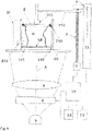
- Figure 4 shows a schematic diagram of a stereolithography apparatus according to prior art.
- bottom wall or bottom of the vat refers to the more general term first wall and the term platform or movable platform refers to the more general term second movable wall.
- light radiation is not limited to the visible spectrum field but it implies any type of electromagnetic radiation able to generate a polymerization of the resin.
- the term transparent comprises both transparent for the radiation in the spectrum field of the visible electromagnetic radiation and for the radiation of not visible frequencies.
- the device comprises a vat 1 containing a predetermined amount of resin sufficient for producing the desired object O.
- the vat has a transparent bottom wall 101.
- the resin RE is contained therein.
- a movable platform 2 In a facing position, namely opposing the bottom side, there is provided a movable platform 2 whose side facing the bottom side is the so called build plane.
- the movable platform 2 is supported so as to be vertically movable, that is in the direction perpendicular to the extension thereof and of the bottom 101 of the vat 2.
- Movement means can be of any type and in the figure, merely by way of example, these are composed of a vertically oriented threaded shaft 3.
- the threaded shaft is operated so as to rotate about its own axis by a motor 4.
- the movable platform 2 is supported so as to be movable parallel to itself by means of a support bracket 102 provided with a threaded hole engaging the threaded shaft.
- the support bracket 2 is locked as regards the rotation about the axis of the threaded shaft 3, but it axially slides along it, therefore the rotation of the shaft by the motor 4 causes the platform 2 to vertically translate.
- the platform 2 is translated away from or close to the bottom 101 of the vat 1.
- the surface of the platform 2 facing the bottom 101 of the vat 1 is the surface for adhesion of the resin upon polymerization.
- a light source 5 irradiates the resin with a field of electromagnetic energy having a predetermined intensity distribution in the plane corresponding to a section plane or a section layer and to the shape of the object O along said section plane or said slice or layer of the object O and in the direction of the optical axis A.
- the intensity distribution of the radiation is generated by a transparent screen or the like 6 that has a transmissivity variable in non-uniform manner along its extension and the radiation is focused by an optical assembly 8 on the transparent bottom of the vat 1.
- control unit 10 comprising at least one processor and intended to execute a control software that sets up the processor such to give commands thereto in order to perform functions managing and operating the peripheral units composed of the motor 4, of possible control members generally shown as inserted in the column 11, of the light source 5 and of the screen 6 or another device modulating the intensity distribution of the light radiation correspondingly to the shape of the object in the several section planes.
- a user interface 12 allows operating parameters to be configured, set or allows operating conditions of the apparatus to be displayed.
- a memory 13 is configured to contain the control program and possible further parameters, such as for example data about digitalized drawings or digitalized images for example by means of 3D CAD drawings of the object, of the several sections that have to be made in sequence and therefore that have to be used to modulate, by the control unit 10 and the screen 6, the light radiation irradiating the resin correspondingly to the sequence of section planes or layers of the object correspondingly to the relative position of the movable wall with respect to the bottom wall of the vat 1.
- the production process provides the platform 2 to be placed at an initial distance from the bottom 101 of the vat 1 equal to the thickness of a first layer of resin to be cured.
- the light radiation generating source 5 generates a light radiation that irradiates the resin layer comprised between the bottom 101 of the vat 1 and the movable platform 2.
- the object O is produced by a sequence of slices or layers thereof along predetermined section planes.
- a drawing is projected on the resin layer which corresponds to the section of the body under production along said predetermined layer or said predetermined slice of the desired object, such that each resin layer is cured in a manner corresponding to the section image associated thereto.
- the resin RE subjected to radiation, is cured and solidified, creating a layer or slice of the desired object.
- the movable platform 2 is moved away with respect to the bottom 101 of the vat 1, such to detach the layer formed just now from the bottom of the vat 1.
- the resin layer cured just now is placed at a distance from the bottom 101 of the vat 1 for an extent equal to the thickness of the following layer to be produced and a layer of resin to be cured with a corresponding thickness is placed between the resin layer cured in the immediately preceding step and the bottom 101 of the vat. Therefore the image of the corresponding section slice of the desired object is projected thereon and therefore also such resin layer is cured.
- the process is repeated till the complete polymerization, layer after layer, of all the slices the object is divided into till completely producing the object O to be created.
- the speed with which the platform 2 is moved away can be adjusted according to different criteria, for example, but not as a limitation, on the basis of the amount of resin to be cured for each layer and on the basis of the size of the layer of resin to be cured.
- the process provides a continuous movement of the platform 2 with respect to the bottom wall 101 of the vat.
- the distance between the bottom wall 101 and the platform 2 corresponds to a predetermined univocal position of a section plane along an axis of the object to be produced parallel to the direction of movement of the movable platform 2.
- the section plane moves along said axis in a manner synchronized with the movement of the movable platform with respect to the bottom wall 101 of the vat 1 and the intensity distribution of the light radiation changes correspondingly to the shape of the object along the sequence of the section planes synchronized with the movement of the movable platform 2 and correspondingly to a polymerization of the resin to reproduce the shape of the object in the section plane.
- both the solution by steps and the continuous solution can be applied, as well as the inventive concept can be provided in combination with any variant of the production process and of the relevant apparatus carrying out the process, the invention being substantially intended for the improvement regarding the combination of vat and movable platform, therefore any production process and relevant apparatus for carrying it out requiring two opposite walls 101 and 2 movable with respect to each other according to a direction transverse thereto can be provided in combination with the teaching of the present invention.
- Figures 1 to 3 show three operating conditions of a first embodiment of the apparatus according to the present invention.
- the apparatus according to the present invention has a construction substantially similar to the schematic one described with reference to figure 4 and the principle operating manners are the same.
- the main difference between the schematic diagram and the present invention is the fact that the transparent bottom side 101 of the vat 1, the vat 1 and the movable platform 2 are removably mountable to supports of the apparatus and together are a separate part of the apparatus intended to produce only one object, at the end of the production process it becoming an enclosure or container for the finished object.
- the wall acting as the bottom wall 101 of the vat 1 is temporarily removably fastenable to a stationary support that in figure 4 is schematized by the surface 40 provided with an opening 140 for the passage of the polymerization light radiation according to the above mentioned principle manners.
- the movable platform 2 forms a wall substantially parallel to the wall 101. This upper wall is removably connectable to the vertical translation means (z axis parallel to the axis of the threaded shaft 3 in figure 4 ) .
- connection to z-axis movement means may occur by means removably fastening to the bracket 102, such as for example screw or tightening bolt means or a fastening flange that connect the face of the platform opposite to the bottom 101 of the vat 1 with the bracket 102.
- such means are composed of a flanged fastening pin 301.
- the removable fastening means both for the side 101 and the platform 2 can be any and the person skilled in the art has available a wide choice among different options present in his/her basic technical knowledge.
- a perimetral shell wall 30 connects the edges or perimetral bands of the transparent bottom wall 101 and of the wall acting as the platform 2, forming side walls acting as containing side walls of the vat in conventional apparatuses such as that in figure 4 and delimiting, without interruption, a chamber 31 tightly sealing it towards the outside.
- the chamber 31 is delimited by the bottom wall 101 by the wall overlapping the bottom wall forming the movable platform 2 and by the shell wall 30.
- Such assembly of walls forms a cartridge or capsule that is more generally a removable container completely sealed towards the outside and where at the beginning a predetermined amount of resin, not cured yet, is contained.
- the shell wall 30 is extensible or it can be extended in a direction parallel to the direction moving away the two walls 101 and 2 with respect to each other.
- the solution shown in figures provides a membrane of flexible material like a sleeve whose axial extension corresponds to the farthest position of the two walls 101 and 2 with respect to each other or slightly higher than that.
- the volume enclosed in the chamber delimited by the two walls 101, 2 and by the shell wall 30 has a constant volume, since the membrane forming the shell wall is arranged with a radial bowing orientation with respect to the axis of the sleeve shape.
- the flexible membrane extends in the direction moving away the two walls recovering the extension length from the richness of the radial or side bowing.
- the membrane can be selected as a barrier to particles with a predetermined grain size or as a barrier to specific gases or as a barrier to particles and barrier to gases.
- Particles mean not only particles of inanimate material but also exponents of bacterial flora and fauna or the like.
- Figures 1 to 3 show a sequence of the production process.
- a cartridge comprising a wall acting as movable platform 2, an opposite wall acting as transparent bottom 101 and a perimetral extensible shell wall 30 is mounted in a polymerization printing apparatus 3 by fastening the bottom 101 to the stationary support 40 and the platform 2 to the bracket 102 respectively.
- the stationary support and the bracket 102 are in the closest position therefore the cartridge composed of the wall acting as movable platform 2, of the opposite wall acting as transparent bottom 101 and of the perimetral extensible shell wall 30 has the two walls forming the bottom side 101 and the platform 2 in the closest position.
- the sealed chamber 31 contains an amount of resin proportioned to the production of the desired object O.
- the process begins and the movable platform 2 is vertically dragged in the z axis direction by the bracket 102 with reference to the example of the apparatus of figure 4 .
- the movable platform 2 is moved to the highest distance from the bottom 101 coinciding with all the layers forming the complete object O being cured.
- the membrane forming the shell wall 30 in the form of the flexible sleeve reaches its maximum extension, while it remains constrained without interruption to the bottom 101 and to the platform 2 while maintaining the chamber 31 in the sealed condition towards the outside.
- the chamber 31 now has become a sealed container for the produced object O and where the object can be kept and stored till its first use.
- Such container can be removed from supports 102 and 40 of the apparatus and is a unit element with the produced object contained therein as shown in figure 8 .
- the shell wall 30 is for example composed of an extensible membrane.
- At least in some embodiments it is possible to provide a system compensating the pressure drop generated in the chamber 31 due to the increase in the volume thereof.
- a compensating valve that opens on the basis of the difference of pressure inside the chamber with respect to the one present outside the chamber and which valve can be coupled to a filtering system or to a tank for compensation gas having a controlled purity.
- the chamber 31 can be associated to compensating plenum chamber for example in the form of a bladder or a tubular part of the shell wall 30 that is filled beforehand with a gas with such an amount enough to compensate for the pressure drop generated by the increase in volume of the chamber 31 during the production process and which bladder or tubular part is in communication with the inside of the chamber through a valve that opens as a function of the pressure difference between the pressure present in the chamber 31 and that present in the bladder or tubular part of the shell wall 30.
- the cartridge in itself does not exhibit a complicated construction both as regards construction parts and as regards their assembling, and it does not require expensive materials or materials difficult to be found.
- the advantage is a constant and continuous protection against contamination effects, due to the contact with the external environment, that begin before the production process, namely at the moment when the resin to be cured is supplied and these effects end only upon the first use of the finished product.
- a suitable construction of the extensible shell wall also in the form of several layers, each one dedicated to a specific barrier effect against specific and different contaminants, allows the protection against contaminations from agents present in the environment to be calibrated according to specific needs of the applications to which the produced object is intended thus avoiding excessive protection costs to be provided when it is not necessary.
- Figure 5 shows a further variant embodiment.
- vat 1, bottom wall 101, movable platform 2 is made as a cylinder piston unit, preferably but not necessarily with a cylindrical cross-section.
- the wall 101 and the side wall of the vat 1 form the cylinder part wherein the movable platform 2 sealingly slides in the direction of the axis of the side wall of the vat 1 as schematically shown by the peripheral gasket 202 associated to the platform 2.
- the cylindrical vat 1 and the movable wall 2 acting as a piston are firmly connected to the supports of the apparatus and in order to remove the workpiece it is necessary to completely remove the movable platform 2 from the vat 1 by opening the inner compartment to the outside.
- a variant provides such action to be carried out also to supply the amount of resin necessary to produce the desired object.
- a variant shown by dashed lines on the contrary shows a resin tank 50 connected to an inlet of the vat 1. Therefore the resin is only drawn by the suction generated by moving the movable platform 2 as a syringe or it is possible also to provide a pump or the like for the controlled supply of the resin that often is relatively viscous.
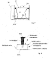
- Figure 6 shows a further variant embodiment of the embodiment according to figure 5 .
- the wall 101, the side wall of the vat 1 and the movable platform 2 form, like figure 5 , a cylinder piston unit preferably with a cylindrical section however the walls 101 and 2 can be removed from the supports of the apparatus.
- the platform 2 is shown fastenable in a removable manner to the bracket 102 by means of a joint or removable fastening fitting that can be made in any manner as already described with reference to the example of figures 1 to 3 .
- the wall 101 that forms the bottom of the vat is removably fastened to the corresponding support 40 for example as that described in figures 1 to 3 .
- the resin can be housed in the vat 1 or the resin can be housed in a tank 50 and progressively fed in the vat 1 through a communication aperture openable and closable by means of removable closure means such as for example the valve 302.
- the containment chamber can act as a container for the finished object and can be used for producing a plurality of objects, while in the second embodiment of figure 6 the cylinder piston assembly remains constrained to the finished product and can be used only for producing such product.
Landscapes
- Chemical & Material Sciences (AREA)
- Engineering & Computer Science (AREA)
- Materials Engineering (AREA)
- Physics & Mathematics (AREA)
- Manufacturing & Machinery (AREA)
- Mechanical Engineering (AREA)
- Optics & Photonics (AREA)
Applications Claiming Priority (1)
| Application Number | Priority Date | Filing Date | Title |
|---|---|---|---|
| IT102017000007862A IT201700007862A1 (it) | 2017-01-25 | 2017-01-25 | Dispositivo per la produzione di oggetti attraverso stereolitografia e metodo per la produzione di oggetti attraverso stereolitografia |
Publications (2)
| Publication Number | Publication Date |
|---|---|
| EP3354442A1 EP3354442A1 (en) | 2018-08-01 |
| EP3354442B1 true EP3354442B1 (en) | 2022-06-29 |
Family
ID=58779290
Family Applications (1)
| Application Number | Title | Priority Date | Filing Date |
|---|---|---|---|
| EP18151134.6A Active EP3354442B1 (en) | 2017-01-25 | 2018-01-11 | Apparatus for producing objects by stereolithography and method for producing objects by stereolithography |
Country Status (2)
| Country | Link |
|---|---|
| EP (1) | EP3354442B1 (it) |
| IT (1) | IT201700007862A1 (it) |
Families Citing this family (11)
| Publication number | Priority date | Publication date | Assignee | Title |
|---|---|---|---|---|
| EP3643479B1 (de) * | 2018-10-24 | 2021-01-06 | Ivoclar Vivadent AG | Verfahren und vorrichtung zum aufbau eines formkörpers durch stereolithographisches aushärten von baumaterial durch photopolymerisation |
| EP3702052B1 (en) * | 2019-02-28 | 2024-07-31 | Sirona Dental Systems GmbH | Component carrier for an additive manufacturing device |
| CN110539482B (zh) * | 2019-09-23 | 2021-04-30 | 深圳摩方新材科技有限公司 | 一种高速树脂涂层3d打印系统 |
| GB2588607A (en) * | 2019-10-28 | 2021-05-05 | Photocentric Ltd | Method of 3D printing in a chamber of adjustable volume using LCD screens as the method of polymerisation |
| CN110722795B (zh) * | 2019-11-21 | 2022-02-22 | 吉林大学 | 一种一次成型的多面lcd光源3d打印装置 |
| CN114643714B (zh) * | 2020-12-19 | 2024-05-17 | 深圳市创想三维科技有限公司 | 光固化3d打印方法、电子装置及存储介质 |
| JP7797835B2 (ja) * | 2021-11-15 | 2026-01-14 | 株式会社Jvcケンウッド | 光造形装置および造形物の製造方法 |
| JP7797837B2 (ja) * | 2021-11-15 | 2026-01-14 | 株式会社Jvcケンウッド | 光造形装置および造形物の製造方法 |
| WO2023084930A1 (ja) * | 2021-11-15 | 2023-05-19 | 株式会社Jvcケンウッド | 光造形装置および造形物の製造方法 |
| JP7797838B2 (ja) * | 2021-11-15 | 2026-01-14 | 株式会社Jvcケンウッド | 光造形装置および造形物の製造方法 |
| WO2025080715A1 (en) * | 2023-10-10 | 2025-04-17 | Auxilium Biotechnologies Inc. | Systems and methods for micromanufacturing and bioprinting in a micro gravity environment thereof |
Family Cites Families (1)
| Publication number | Priority date | Publication date | Assignee | Title |
|---|---|---|---|---|
| AT516324B1 (de) * | 2014-07-22 | 2016-06-15 | Way To Production Gmbh | System zum Bilden eines formstabilen Objektes durch selektives, bereichsweises Verfestigen einer nicht formstabilen Masse |
-
2017
- 2017-01-25 IT IT102017000007862A patent/IT201700007862A1/it unknown
-
2018
- 2018-01-11 EP EP18151134.6A patent/EP3354442B1/en active Active
Also Published As
| Publication number | Publication date |
|---|---|
| EP3354442A1 (en) | 2018-08-01 |
| IT201700007862A1 (it) | 2018-07-25 |
Similar Documents
| Publication | Publication Date | Title |
|---|---|---|
| EP3354442B1 (en) | Apparatus for producing objects by stereolithography and method for producing objects by stereolithography | |
| US12103225B2 (en) | Stereolithography device comprising cartridge device | |
| JP5975240B2 (ja) | 光造形機用カートリッジ、光造形機用カートリッジを備える光造形機および光造形機用カートリッジの製造方法 | |
| JP7360890B2 (ja) | 光重合による構築材料の光造形凝固によって成形体を構築する方法およびデバイス | |
| JP4856102B2 (ja) | 立体造形装置及び方法のためのカートリッジ | |
| JP4778005B2 (ja) | 立体造形装置及び方法 | |
| US7118206B1 (en) | Gas bubble removal from ink-jet dispensing devices | |
| JP2008173974A (ja) | 立体造形装置における像形成装置及び整合性のある反復が可能な位置合せのための方法 | |
| KR102144300B1 (ko) | 축조 재료 용기 | |
| US11220045B2 (en) | Apparatus and method for manufacturing a three-dimensional object | |
| JP7321755B2 (ja) | 吐出材充填装置 | |
| JP6909291B2 (ja) | 光造形装置用の原料供給装置 | |
| JP2016071252A (ja) | 光ファイバ再被覆装置 | |
| US20210170675A1 (en) | Stereolithography apparatus equipped with resin capsule and method of operating said apparatus | |
| FI128627B (en) | Stereolithography equipment provided with resin collection mechanism and method for operating said equipment | |
| US20250312971A1 (en) | Cartridge with built-in reservoir and build plate for additive manufacturing devices | |
| KR101647800B1 (ko) | Pc 일체형 3d 프린터 | |
| HK1225693A1 (en) | Cartride for a stereolithography machine and method for using the same, and stereolithography machine |
Legal Events
| Date | Code | Title | Description |
|---|---|---|---|
| PUAI | Public reference made under article 153(3) epc to a published international application that has entered the european phase |
Free format text: ORIGINAL CODE: 0009012 |
|
| STAA | Information on the status of an ep patent application or granted ep patent |
Free format text: STATUS: THE APPLICATION HAS BEEN PUBLISHED |
|
| AK | Designated contracting states |
Kind code of ref document: A1 Designated state(s): AL AT BE BG CH CY CZ DE DK EE ES FI FR GB GR HR HU IE IS IT LI LT LU LV MC MK MT NL NO PL PT RO RS SE SI SK SM TR |
|
| AX | Request for extension of the european patent |
Extension state: BA ME |
|
| STAA | Information on the status of an ep patent application or granted ep patent |
Free format text: STATUS: REQUEST FOR EXAMINATION WAS MADE |
|
| 17P | Request for examination filed |
Effective date: 20190117 |
|
| RBV | Designated contracting states (corrected) |
Designated state(s): AL AT BE BG CH CY CZ DE DK EE ES FI FR GB GR HR HU IE IS IT LI LT LU LV MC MK MT NL NO PL PT RO RS SE SI SK SM TR |
|
| STAA | Information on the status of an ep patent application or granted ep patent |
Free format text: STATUS: EXAMINATION IS IN PROGRESS |
|
| 17Q | First examination report despatched |
Effective date: 20201126 |
|
| GRAP | Despatch of communication of intention to grant a patent |
Free format text: ORIGINAL CODE: EPIDOSNIGR1 |
|
| STAA | Information on the status of an ep patent application or granted ep patent |
Free format text: STATUS: GRANT OF PATENT IS INTENDED |
|
| INTG | Intention to grant announced |
Effective date: 20211210 |
|
| GRAS | Grant fee paid |
Free format text: ORIGINAL CODE: EPIDOSNIGR3 |
|
| GRAJ | Information related to disapproval of communication of intention to grant by the applicant or resumption of examination proceedings by the epo deleted |
Free format text: ORIGINAL CODE: EPIDOSDIGR1 |
|
| GRAL | Information related to payment of fee for publishing/printing deleted |
Free format text: ORIGINAL CODE: EPIDOSDIGR3 |
|
| STAA | Information on the status of an ep patent application or granted ep patent |
Free format text: STATUS: EXAMINATION IS IN PROGRESS |
|
| GRAP | Despatch of communication of intention to grant a patent |
Free format text: ORIGINAL CODE: EPIDOSNIGR1 |
|
| STAA | Information on the status of an ep patent application or granted ep patent |
Free format text: STATUS: GRANT OF PATENT IS INTENDED |
|
| INTC | Intention to grant announced (deleted) | ||
| INTG | Intention to grant announced |
Effective date: 20220429 |
|
| GRAA | (expected) grant |
Free format text: ORIGINAL CODE: 0009210 |
|
| STAA | Information on the status of an ep patent application or granted ep patent |
Free format text: STATUS: THE PATENT HAS BEEN GRANTED |
|
| AK | Designated contracting states |
Kind code of ref document: B1 Designated state(s): AL AT BE BG CH CY CZ DE DK EE ES FI FR GB GR HR HU IE IS IT LI LT LU LV MC MK MT NL NO PL PT RO RS SE SI SK SM TR |
|
| REG | Reference to a national code |
Ref country code: CH Ref legal event code: EP |
|
| REG | Reference to a national code |
Ref country code: AT Ref legal event code: REF Ref document number: 1501039 Country of ref document: AT Kind code of ref document: T Effective date: 20220715 |
|
| REG | Reference to a national code |
Ref country code: IE Ref legal event code: FG4D |
|
| REG | Reference to a national code |
Ref country code: DE Ref legal event code: R096 Ref document number: 602018037199 Country of ref document: DE |
|
| REG | Reference to a national code |
Ref country code: LT Ref legal event code: MG9D |
|
| PG25 | Lapsed in a contracting state [announced via postgrant information from national office to epo] |
Ref country code: SE Free format text: LAPSE BECAUSE OF FAILURE TO SUBMIT A TRANSLATION OF THE DESCRIPTION OR TO PAY THE FEE WITHIN THE PRESCRIBED TIME-LIMIT Effective date: 20220629 Ref country code: NO Free format text: LAPSE BECAUSE OF FAILURE TO SUBMIT A TRANSLATION OF THE DESCRIPTION OR TO PAY THE FEE WITHIN THE PRESCRIBED TIME-LIMIT Effective date: 20220929 Ref country code: LT Free format text: LAPSE BECAUSE OF FAILURE TO SUBMIT A TRANSLATION OF THE DESCRIPTION OR TO PAY THE FEE WITHIN THE PRESCRIBED TIME-LIMIT Effective date: 20220629 Ref country code: HR Free format text: LAPSE BECAUSE OF FAILURE TO SUBMIT A TRANSLATION OF THE DESCRIPTION OR TO PAY THE FEE WITHIN THE PRESCRIBED TIME-LIMIT Effective date: 20220629 Ref country code: GR Free format text: LAPSE BECAUSE OF FAILURE TO SUBMIT A TRANSLATION OF THE DESCRIPTION OR TO PAY THE FEE WITHIN THE PRESCRIBED TIME-LIMIT Effective date: 20220930 Ref country code: FI Free format text: LAPSE BECAUSE OF FAILURE TO SUBMIT A TRANSLATION OF THE DESCRIPTION OR TO PAY THE FEE WITHIN THE PRESCRIBED TIME-LIMIT Effective date: 20220629 Ref country code: BG Free format text: LAPSE BECAUSE OF FAILURE TO SUBMIT A TRANSLATION OF THE DESCRIPTION OR TO PAY THE FEE WITHIN THE PRESCRIBED TIME-LIMIT Effective date: 20220929 |
|
| REG | Reference to a national code |
Ref country code: NL Ref legal event code: MP Effective date: 20220629 |
|
| REG | Reference to a national code |
Ref country code: AT Ref legal event code: MK05 Ref document number: 1501039 Country of ref document: AT Kind code of ref document: T Effective date: 20220629 |
|
| PG25 | Lapsed in a contracting state [announced via postgrant information from national office to epo] |
Ref country code: RS Free format text: LAPSE BECAUSE OF FAILURE TO SUBMIT A TRANSLATION OF THE DESCRIPTION OR TO PAY THE FEE WITHIN THE PRESCRIBED TIME-LIMIT Effective date: 20220629 Ref country code: LV Free format text: LAPSE BECAUSE OF FAILURE TO SUBMIT A TRANSLATION OF THE DESCRIPTION OR TO PAY THE FEE WITHIN THE PRESCRIBED TIME-LIMIT Effective date: 20220629 |
|
| PG25 | Lapsed in a contracting state [announced via postgrant information from national office to epo] |
Ref country code: NL Free format text: LAPSE BECAUSE OF FAILURE TO SUBMIT A TRANSLATION OF THE DESCRIPTION OR TO PAY THE FEE WITHIN THE PRESCRIBED TIME-LIMIT Effective date: 20220629 |
|
| PG25 | Lapsed in a contracting state [announced via postgrant information from national office to epo] |
Ref country code: SM Free format text: LAPSE BECAUSE OF FAILURE TO SUBMIT A TRANSLATION OF THE DESCRIPTION OR TO PAY THE FEE WITHIN THE PRESCRIBED TIME-LIMIT Effective date: 20220629 Ref country code: SK Free format text: LAPSE BECAUSE OF FAILURE TO SUBMIT A TRANSLATION OF THE DESCRIPTION OR TO PAY THE FEE WITHIN THE PRESCRIBED TIME-LIMIT Effective date: 20220629 Ref country code: RO Free format text: LAPSE BECAUSE OF FAILURE TO SUBMIT A TRANSLATION OF THE DESCRIPTION OR TO PAY THE FEE WITHIN THE PRESCRIBED TIME-LIMIT Effective date: 20220629 Ref country code: PT Free format text: LAPSE BECAUSE OF FAILURE TO SUBMIT A TRANSLATION OF THE DESCRIPTION OR TO PAY THE FEE WITHIN THE PRESCRIBED TIME-LIMIT Effective date: 20221031 Ref country code: ES Free format text: LAPSE BECAUSE OF FAILURE TO SUBMIT A TRANSLATION OF THE DESCRIPTION OR TO PAY THE FEE WITHIN THE PRESCRIBED TIME-LIMIT Effective date: 20220629 Ref country code: EE Free format text: LAPSE BECAUSE OF FAILURE TO SUBMIT A TRANSLATION OF THE DESCRIPTION OR TO PAY THE FEE WITHIN THE PRESCRIBED TIME-LIMIT Effective date: 20220629 Ref country code: AT Free format text: LAPSE BECAUSE OF FAILURE TO SUBMIT A TRANSLATION OF THE DESCRIPTION OR TO PAY THE FEE WITHIN THE PRESCRIBED TIME-LIMIT Effective date: 20220629 |
|
| PG25 | Lapsed in a contracting state [announced via postgrant information from national office to epo] |
Ref country code: PL Free format text: LAPSE BECAUSE OF FAILURE TO SUBMIT A TRANSLATION OF THE DESCRIPTION OR TO PAY THE FEE WITHIN THE PRESCRIBED TIME-LIMIT Effective date: 20220629 Ref country code: IS Free format text: LAPSE BECAUSE OF FAILURE TO SUBMIT A TRANSLATION OF THE DESCRIPTION OR TO PAY THE FEE WITHIN THE PRESCRIBED TIME-LIMIT Effective date: 20221029 |
|
| REG | Reference to a national code |
Ref country code: DE Ref legal event code: R097 Ref document number: 602018037199 Country of ref document: DE |
|
| PG25 | Lapsed in a contracting state [announced via postgrant information from national office to epo] |
Ref country code: AL Free format text: LAPSE BECAUSE OF FAILURE TO SUBMIT A TRANSLATION OF THE DESCRIPTION OR TO PAY THE FEE WITHIN THE PRESCRIBED TIME-LIMIT Effective date: 20220629 |
|
| PG25 | Lapsed in a contracting state [announced via postgrant information from national office to epo] |
Ref country code: DK Free format text: LAPSE BECAUSE OF FAILURE TO SUBMIT A TRANSLATION OF THE DESCRIPTION OR TO PAY THE FEE WITHIN THE PRESCRIBED TIME-LIMIT Effective date: 20220629 Ref country code: CZ Free format text: LAPSE BECAUSE OF FAILURE TO SUBMIT A TRANSLATION OF THE DESCRIPTION OR TO PAY THE FEE WITHIN THE PRESCRIBED TIME-LIMIT Effective date: 20220629 |
|
| PLBE | No opposition filed within time limit |
Free format text: ORIGINAL CODE: 0009261 |
|
| STAA | Information on the status of an ep patent application or granted ep patent |
Free format text: STATUS: NO OPPOSITION FILED WITHIN TIME LIMIT |
|
| 26N | No opposition filed |
Effective date: 20230330 |
|
| PG25 | Lapsed in a contracting state [announced via postgrant information from national office to epo] |
Ref country code: SI Free format text: LAPSE BECAUSE OF FAILURE TO SUBMIT A TRANSLATION OF THE DESCRIPTION OR TO PAY THE FEE WITHIN THE PRESCRIBED TIME-LIMIT Effective date: 20220629 |
|
| PG25 | Lapsed in a contracting state [announced via postgrant information from national office to epo] |
Ref country code: IT Free format text: LAPSE BECAUSE OF FAILURE TO SUBMIT A TRANSLATION OF THE DESCRIPTION OR TO PAY THE FEE WITHIN THE PRESCRIBED TIME-LIMIT Effective date: 20220629 |
|
| PG25 | Lapsed in a contracting state [announced via postgrant information from national office to epo] |
Ref country code: BG Free format text: LAPSE BECAUSE OF FAILURE TO SUBMIT A TRANSLATION OF THE DESCRIPTION OR TO PAY THE FEE WITHIN THE PRESCRIBED TIME-LIMIT Effective date: 20220629 |
|
| PG25 | Lapsed in a contracting state [announced via postgrant information from national office to epo] |
Ref country code: BG Free format text: LAPSE BECAUSE OF FAILURE TO SUBMIT A TRANSLATION OF THE DESCRIPTION OR TO PAY THE FEE WITHIN THE PRESCRIBED TIME-LIMIT Effective date: 20220629 |
|
| PGFP | Annual fee paid to national office [announced via postgrant information from national office to epo] |
Ref country code: MC Payment date: 20241220 Year of fee payment: 8 |
|
| PGFP | Annual fee paid to national office [announced via postgrant information from national office to epo] |
Ref country code: BE Payment date: 20241218 Year of fee payment: 8 Ref country code: LU Payment date: 20241218 Year of fee payment: 8 |
|
| PGFP | Annual fee paid to national office [announced via postgrant information from national office to epo] |
Ref country code: GB Payment date: 20241211 Year of fee payment: 8 |
|
| PGFP | Annual fee paid to national office [announced via postgrant information from national office to epo] |
Ref country code: FR Payment date: 20241211 Year of fee payment: 8 |
|
| PGFP | Annual fee paid to national office [announced via postgrant information from national office to epo] |
Ref country code: IE Payment date: 20241211 Year of fee payment: 8 |
|
| PGFP | Annual fee paid to national office [announced via postgrant information from national office to epo] |
Ref country code: MT Payment date: 20241220 Year of fee payment: 8 |
|
| PGFP | Annual fee paid to national office [announced via postgrant information from national office to epo] |
Ref country code: DE Payment date: 20241218 Year of fee payment: 8 |
|
| PGFP | Annual fee paid to national office [announced via postgrant information from national office to epo] |
Ref country code: CH Payment date: 20250201 Year of fee payment: 8 |
|
| PG25 | Lapsed in a contracting state [announced via postgrant information from national office to epo] |
Ref country code: CY Free format text: LAPSE BECAUSE OF FAILURE TO SUBMIT A TRANSLATION OF THE DESCRIPTION OR TO PAY THE FEE WITHIN THE PRESCRIBED TIME-LIMIT; INVALID AB INITIO Effective date: 20180111 |
|
| PG25 | Lapsed in a contracting state [announced via postgrant information from national office to epo] |
Ref country code: HU Free format text: LAPSE BECAUSE OF FAILURE TO SUBMIT A TRANSLATION OF THE DESCRIPTION OR TO PAY THE FEE WITHIN THE PRESCRIBED TIME-LIMIT; INVALID AB INITIO Effective date: 20180111 |
|
| PG25 | Lapsed in a contracting state [announced via postgrant information from national office to epo] |
Ref country code: TR Free format text: LAPSE BECAUSE OF FAILURE TO SUBMIT A TRANSLATION OF THE DESCRIPTION OR TO PAY THE FEE WITHIN THE PRESCRIBED TIME-LIMIT Effective date: 20220629 |