EP3354448B1 - Mandrin pour la fabrication et la réparation de pièces composites - Google Patents
Mandrin pour la fabrication et la réparation de pièces composites Download PDFInfo
- Publication number
- EP3354448B1 EP3354448B1 EP17203705.3A EP17203705A EP3354448B1 EP 3354448 B1 EP3354448 B1 EP 3354448B1 EP 17203705 A EP17203705 A EP 17203705A EP 3354448 B1 EP3354448 B1 EP 3354448B1
- Authority
- EP
- European Patent Office
- Prior art keywords
- mandrel
- mandrel portion
- actuator
- mid
- cavity
- Prior art date
- Legal status (The legal status is an assumption and is not a legal conclusion. Google has not performed a legal analysis and makes no representation as to the accuracy of the status listed.)
- Active
Links
Images





Classifications
-
- B—PERFORMING OPERATIONS; TRANSPORTING
- B29—WORKING OF PLASTICS; WORKING OF SUBSTANCES IN A PLASTIC STATE IN GENERAL
- B29C—SHAPING OR JOINING OF PLASTICS; SHAPING OF MATERIAL IN A PLASTIC STATE, NOT OTHERWISE PROVIDED FOR; AFTER-TREATMENT OF THE SHAPED PRODUCTS, e.g. REPAIRING
- B29C70/00—Shaping composites, i.e. plastics material comprising reinforcements, fillers or preformed parts, e.g. inserts
- B29C70/04—Shaping composites, i.e. plastics material comprising reinforcements, fillers or preformed parts, e.g. inserts comprising reinforcements only, e.g. self-reinforcing plastics
- B29C70/28—Shaping operations therefor
- B29C70/30—Shaping by lay-up, i.e. applying fibres, tape or broadsheet on a mould, former or core; Shaping by spray-up, i.e. spraying of fibres on a mould, former or core
- B29C70/34—Shaping by lay-up, i.e. applying fibres, tape or broadsheet on a mould, former or core; Shaping by spray-up, i.e. spraying of fibres on a mould, former or core and shaping or impregnating by compression, i.e. combined with compressing after the lay-up operation
-
- B—PERFORMING OPERATIONS; TRANSPORTING
- B29—WORKING OF PLASTICS; WORKING OF SUBSTANCES IN A PLASTIC STATE IN GENERAL
- B29C—SHAPING OR JOINING OF PLASTICS; SHAPING OF MATERIAL IN A PLASTIC STATE, NOT OTHERWISE PROVIDED FOR; AFTER-TREATMENT OF THE SHAPED PRODUCTS, e.g. REPAIRING
- B29C33/00—Moulds or cores; Details thereof or accessories therefor
- B29C33/44—Moulds or cores; Details thereof or accessories therefor with means for, or specially constructed to facilitate, the removal of articles, e.g. of undercut articles
- B29C33/48—Moulds or cores; Details thereof or accessories therefor with means for, or specially constructed to facilitate, the removal of articles, e.g. of undercut articles with means for collapsing or disassembling
- B29C33/485—Moulds or cores; Details thereof or accessories therefor with means for, or specially constructed to facilitate, the removal of articles, e.g. of undercut articles with means for collapsing or disassembling cores or mandrels
-
- B—PERFORMING OPERATIONS; TRANSPORTING
- B29—WORKING OF PLASTICS; WORKING OF SUBSTANCES IN A PLASTIC STATE IN GENERAL
- B29C—SHAPING OR JOINING OF PLASTICS; SHAPING OF MATERIAL IN A PLASTIC STATE, NOT OTHERWISE PROVIDED FOR; AFTER-TREATMENT OF THE SHAPED PRODUCTS, e.g. REPAIRING
- B29C70/00—Shaping composites, i.e. plastics material comprising reinforcements, fillers or preformed parts, e.g. inserts
- B29C70/04—Shaping composites, i.e. plastics material comprising reinforcements, fillers or preformed parts, e.g. inserts comprising reinforcements only, e.g. self-reinforcing plastics
- B29C70/28—Shaping operations therefor
- B29C70/30—Shaping by lay-up, i.e. applying fibres, tape or broadsheet on a mould, former or core; Shaping by spray-up, i.e. spraying of fibres on a mould, former or core
- B29C70/34—Shaping by lay-up, i.e. applying fibres, tape or broadsheet on a mould, former or core; Shaping by spray-up, i.e. spraying of fibres on a mould, former or core and shaping or impregnating by compression, i.e. combined with compressing after the lay-up operation
- B29C70/342—Shaping by lay-up, i.e. applying fibres, tape or broadsheet on a mould, former or core; Shaping by spray-up, i.e. spraying of fibres on a mould, former or core and shaping or impregnating by compression, i.e. combined with compressing after the lay-up operation using isostatic pressure
-
- B—PERFORMING OPERATIONS; TRANSPORTING
- B29—WORKING OF PLASTICS; WORKING OF SUBSTANCES IN A PLASTIC STATE IN GENERAL
- B29C—SHAPING OR JOINING OF PLASTICS; SHAPING OF MATERIAL IN A PLASTIC STATE, NOT OTHERWISE PROVIDED FOR; AFTER-TREATMENT OF THE SHAPED PRODUCTS, e.g. REPAIRING
- B29C70/00—Shaping composites, i.e. plastics material comprising reinforcements, fillers or preformed parts, e.g. inserts
- B29C70/04—Shaping composites, i.e. plastics material comprising reinforcements, fillers or preformed parts, e.g. inserts comprising reinforcements only, e.g. self-reinforcing plastics
- B29C70/28—Shaping operations therefor
- B29C70/40—Shaping or impregnating by compression not applied
- B29C70/42—Shaping or impregnating by compression not applied for producing articles of definite length, i.e. discrete articles
- B29C70/44—Shaping or impregnating by compression not applied for producing articles of definite length, i.e. discrete articles using isostatic pressure, e.g. pressure difference-moulding, vacuum bag-moulding, autoclave-moulding or expanding rubber-moulding
- B29C70/446—Moulding structures having an axis of symmetry or at least one channel, e.g. tubular structures, frames
-
- B—PERFORMING OPERATIONS; TRANSPORTING
- B29—WORKING OF PLASTICS; WORKING OF SUBSTANCES IN A PLASTIC STATE IN GENERAL
- B29C—SHAPING OR JOINING OF PLASTICS; SHAPING OF MATERIAL IN A PLASTIC STATE, NOT OTHERWISE PROVIDED FOR; AFTER-TREATMENT OF THE SHAPED PRODUCTS, e.g. REPAIRING
- B29C70/00—Shaping composites, i.e. plastics material comprising reinforcements, fillers or preformed parts, e.g. inserts
- B29C70/04—Shaping composites, i.e. plastics material comprising reinforcements, fillers or preformed parts, e.g. inserts comprising reinforcements only, e.g. self-reinforcing plastics
- B29C70/28—Shaping operations therefor
- B29C70/54—Component parts, details or accessories; Auxiliary operations, e.g. feeding or storage of prepregs or SMC after impregnation or during ageing
-
- B—PERFORMING OPERATIONS; TRANSPORTING
- B29—WORKING OF PLASTICS; WORKING OF SUBSTANCES IN A PLASTIC STATE IN GENERAL
- B29C—SHAPING OR JOINING OF PLASTICS; SHAPING OF MATERIAL IN A PLASTIC STATE, NOT OTHERWISE PROVIDED FOR; AFTER-TREATMENT OF THE SHAPED PRODUCTS, e.g. REPAIRING
- B29C73/00—Repairing of articles made from plastics or substances in a plastic state, e.g. of articles shaped or produced by using techniques covered by this subclass or subclass B29D
- B29C73/04—Repairing of articles made from plastics or substances in a plastic state, e.g. of articles shaped or produced by using techniques covered by this subclass or subclass B29D using preformed elements
-
- B—PERFORMING OPERATIONS; TRANSPORTING
- B29—WORKING OF PLASTICS; WORKING OF SUBSTANCES IN A PLASTIC STATE IN GENERAL
- B29C—SHAPING OR JOINING OF PLASTICS; SHAPING OF MATERIAL IN A PLASTIC STATE, NOT OTHERWISE PROVIDED FOR; AFTER-TREATMENT OF THE SHAPED PRODUCTS, e.g. REPAIRING
- B29C73/00—Repairing of articles made from plastics or substances in a plastic state, e.g. of articles shaped or produced by using techniques covered by this subclass or subclass B29D
- B29C73/24—Apparatus or accessories not otherwise provided for
- B29C73/26—Apparatus or accessories not otherwise provided for for mechanical pretreatment
-
- B—PERFORMING OPERATIONS; TRANSPORTING
- B29—WORKING OF PLASTICS; WORKING OF SUBSTANCES IN A PLASTIC STATE IN GENERAL
- B29D—PRODUCING PARTICULAR ARTICLES FROM PLASTICS OR FROM SUBSTANCES IN A PLASTIC STATE
- B29D99/00—Subject matter not provided for in other groups of this subclass
- B29D99/001—Producing wall or panel-like structures, e.g. for hulls, fuselages, or buildings
- B29D99/0014—Producing wall or panel-like structures, e.g. for hulls, fuselages, or buildings provided with ridges or ribs, e.g. joined ribs
-
- B—PERFORMING OPERATIONS; TRANSPORTING
- B29—WORKING OF PLASTICS; WORKING OF SUBSTANCES IN A PLASTIC STATE IN GENERAL
- B29K—INDEXING SCHEME ASSOCIATED WITH SUBCLASSES B29B, B29C OR B29D, RELATING TO MOULDING MATERIALS OR TO MATERIALS FOR MOULDS, REINFORCEMENTS, FILLERS OR PREFORMED PARTS, e.g. INSERTS
- B29K2105/00—Condition, form or state of moulded material or of the material to be shaped
- B29K2105/06—Condition, form or state of moulded material or of the material to be shaped containing reinforcements, fillers or inserts
- B29K2105/08—Condition, form or state of moulded material or of the material to be shaped containing reinforcements, fillers or inserts of continuous length, e.g. cords, rovings, mats, fabrics, strands or yarns
- B29K2105/0872—Prepregs
-
- B—PERFORMING OPERATIONS; TRANSPORTING
- B29—WORKING OF PLASTICS; WORKING OF SUBSTANCES IN A PLASTIC STATE IN GENERAL
- B29L—INDEXING SCHEME ASSOCIATED WITH SUBCLASS B29C, RELATING TO PARTICULAR ARTICLES
- B29L2031/00—Other particular articles
- B29L2031/30—Vehicles, e.g. ships or aircraft, or body parts thereof
- B29L2031/3076—Aircrafts
- B29L2031/3082—Fuselages
Definitions
- the present invention generally relates to systems and methods for composite parts, and more particularly to a mandrel system and methods for forming and/or repairing composite parts.
- Composite parts such as those used in the manufacture of aircraft, can be constructed using various production methods, such as filament winding, tape placement, overbraid, chop fiber roving, coating, hand lay-up, or other composite processing techniques and curing processes. Most of these processes use a rigid cure tool/mandrel on which composite material is applied and then cured into a rigid composite part. For example, automated fiber placement (AFP) machines may be used to place fiber reinforcements on molds or mandrels to form composite layups. Following, composite parts may be cured within an autoclave that applies heat and pressure to the part during a cure cycle.
- AFP automated fiber placement
- Some composite part geometries include internal cavities that may require a tool such as a supporting bladder, which is placed in the cavity to ensure that the part geometry is properly maintained during application of composite material or when processed under autoclave pressure.
- the supporting bladder may be an inflatable bladder that can easily fit into an internal cavity prior to cure and then be inflated during an autoclave cure process so as to react to the autoclave pressure force applied to the part.
- inflatable bladders are pressurized by venting them to the autoclave pressure through a vacuum bag.
- the bladders that are used to support a composite part (e.g., a stringer or other longitudinal structural piece in a framework) for autoclave curing may not be suitable when alternatively curing the part out-of-autoclave (e.g., as performed with repairs).
- the part and the bladder are exposed to different temperature and pressure conditions than in an autoclave such that an inflatable bladder may not perform properly and could in fact negatively impact final part characteristics.
- Patent document US 4 310 138 A states a self supporting shrinking mandrel including an actuator with a plurality of legs, each terminated by a cross member.
- the legs and cross members are inserted into grooves of a plurality of support members.
- the grooves and cross members cooperate to hold the support members in place making the entire mandrel self supporting.
- the actuator is tapered in cross section along the longitudinal axis which causes a positive shrinking action as the support members are drawn toward the longitudinal axis when the actuator is withdrawn from the combination.
- Patent document WO 2007/148301 A2 states that a fuselage section is fabricated by automatically depositing fibre tapes preimpregnated with resin on an outer surface of a cylindrical mandrel composed of radially retractable mandrel sectors.
- a mandrel for a composite part is defined in claim 1.
- a method of repairing a part with a mandrel is defined in claim 12.
- a method of forming a part with a mandrel is also described that preferably includes laying up a plurality of layers on a trough and positioning a mandrel, in an expanded state, on the plurality of layers in the trough.
- the mandrel includes an upper-mandrel portion, a lower-mandrel portion, and a mid-mandrel portion between the upper-mandrel portion and the lower-mandrel portion.
- the mandrel also includes a cavity defined by the upper-mandrel portion, the lower-mandrel portion, and the mid-mandrel portion.
- the mandrel further includes an actuator, which is movable in the cavity between a first position in the cavity and a second position in the cavity, and an exterior surface defined by the upper-mandrel portion, the lower-mandrel portion, and the mid-mandrel portion.
- a perimeter of the exterior surface has a first length when the actuator is in the first position in the cavity and the perimeter has a second length when the actuator is in the second position in the cavity. The first length is greater than the second length such that the mandrel is in an expanded state when the actuator is in the first position and the mandrel is in the contracted state when the actuator is in the second position.
- the method of forming the part also includes positioning a fuselage skin on the plurality of layers to form an interior space between the plurality of layers and the fuselage skin.
- the mandrel is in the interior space.
- the method further includes co-curing the plurality of layers and the fuselage skin, and moving the actuator from the first position to the second position to contract the mandrel from the expanded state to the contracted state. After contracting the mandrel, the method includes removing the mandrel from the interior space.
- the mandrel can include a housing having a plurality mandrel portions that are positioned to form a cavity and an exterior surface.
- the exterior surface can support a composite part during fabrication and/or repair.
- the mandrel also includes an actuator that is movable in the cavity between a first position in the cavity and a second position in the cavity. When the actuator is in the first position in the cavity, a perimeter of the exterior surface has a first length. When the actuator is in the second position in the cavity, the perimeter of the exterior surface has a second length.
- the first length is greater than the second length such that the mandrel is in an expanded state when the actuator is in the first position and the mandrel is in a contracted state when the actuator is in the second position.
- the mandrel In the expanded state, the mandrel can fill an interior space of the composite part to support the composite part during a fabrication and/or repair process. Whereas, in the contracted state, the mandrel can be inserted into and/or withdrawn from the interior space of the composite part with relative ease and with little (or no) risk of damage to the composite part. Beneficially, the mandrel can also support the composite part during repairs, which may involve applying of out-of-autoclave and/or vacuum bag cure pressure. The mandrel is further reusable since the mandrel can be reduced in size before and/or after cure to be removed from the part.
- the housing can include an upper-mandrel portion, a lower-mandrel portion, and a mid-mandrel portion between the upper-mandrel portion and the lower-mandrel portion.
- the upper-mandrel portion, the lower mandrel portion, and/or the mid-mandrel portion can be movable relative to each other to transition the mandrel between the contracted state and the expanded state.
- the relative movement of the upper-mandrel portion, the lower-mandrel portion, and the mid-mandrel portion can be responsive to an engagement between the actuator and one or more of these portions of the housing as the actuator moves within the cavity between the first position and the second position.
- the mid-mandrel portion can include a first mid-mandrel portion and a second mid-mandrel portion
- the actuator can urge the first and second mid-mandrel portions outwardly away from each other as the actuator moves from the second position to the first position.
- the first mid-mandrel portion and the second mid-mandrel portion can responsively urge the upper-mandrel portion and the lower-mandrel portion away from each other so that the mandrel expands upwardly, downwardly, and laterally when transitioning from the contracted state to the expanded state.
- the mandrel can contract in the same directions when transitioning from the expanded state to the contracted state due to the engagement of the actuator with the portions of the housing and/or the engagement of the portions of the housing with each other.
- the upper-mandrel portion, the lower-mandrel portion, and the mid-mandrel portion can each have a plurality of kerfs along a longitudinal axis extending from a first end of the mandrel to a second end of the mandrel.
- the kerfs can beneficially facilitate bending the mandrel along a non-linear or arcing contour of an interior space of a composite part.
- the actuator can include a plurality of actuator segments coupled to one another by linkages that facilitate bending the actuator along the non-linear or arcing contour of the interior space of the composite part.
- a mandrel 100 can be used to form and/or cure a part layup 102 including multiple plies or layers (not shown) of fiber reinforced polymer resin. Multiple layers of fiber reinforced polymer layers can be laid up over the mandrel 100 to form the layers into a desired part shape.
- the part layup 102 can partially or fully surround the mandrel 100, such that the mandrel 100 is at least substantially enclosed by the part layup 102.
- the mandrel 100 includes a housing 104 in which an actuator 106 is positioned.
- the housing 104 forms an enclosure that can expand outwardly to an expanded state and contract inwardly to a contracted state to responsive to the actuator 106 moving within the housing 104.
- the mandrel 100 can support the part layup 102 during lay-up and/or cure in the expanded state, and the mandrel 100 can be inserted and/or withdrawn from the part layup 102 in the contracted.
- the mandrel 100 can be formed of an elastomeric material, such as Teflon@ (E.I. du Pont de Nemours and Company) coated silicone or hard rubber, and may be pliable to enable the mandrel 100 to conform to various configurations.
- the housing 104 can be formed, for example, from flexible silicon rubber, and thus, the housing 104 can be a flexible housing or an elastomeric housing such that the housing 104 may contact the uncured part layup 102 without damage to the part layup 102 and/or without contamination to the part layup 102.
- the mandrel 100 can be formed by an additive manufacturing process such as, for instance, a three-dimensional printing process.
- Figure 2 illustrates a composite part 200 that may benefit from use of the mandrel 100 to form the part layup 102.
- the composite part 200 is a fiber reinforced composite resin stringer.
- the composite part 200 includes a hat section 202 forming an interior space 204, a pair of laterally extending flange sections 206, and a substantially flat fuselage skin section 208 that is consolidated together with the flange sections 206 during curing.
- hat section 202 forming an interior space 204
- a pair of laterally extending flange sections 206 the composite part 200 includes a substantially flat fuselage skin section 208 that is consolidated together with the flange sections 206 during curing.
- alternative stringer geometries are possible.
- Example composite material used for the composite part 200 may be generally a lightweight material, such as an uncured pre-impregnated reinforcing tape or fabric (i.e., "prepreg").
- the tape or fabric can include a plurality of fibers such as graphite fibers that are embedded within a matrix material, such as a polymer, e.g., an epoxy or phenolic.
- the tape or fabric could be unidirectional or woven depending on a degree of reinforcement desired.
- the prepreg tape or fabric is laid onto the mandrel 100 (or mold) to pre-form the tape or fabric into a desired shape of the composite part 200 as defined by the mandrel 100.
- the composite part 200 can be any suitable dimension to provide various degrees of reinforcement, and could comprise any number of layers of prepreg tape or fabric.
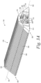
- FIG 3A depicts a perspective view of the housing 104 of the mandrel 100 according to the present invention.
- the housing 104 includes an upper-mandrel portion 310, a lower-mandrel portion 312, a first mid-mandrel portion 314, and a second mid-mandrel portion 316.
- the first mid-mandrel portion 314 and the second mid-mandrel portion 316 are positioned between the upper-mandrel portion 310 and the lower-mandrel portion 312.
- the upper-mandrel portion 310, the lower-mandrel portion 312, the first mid-mandrel portion 314, and the second mid-mandrel portion 316 can be separate structures; however, in alternative examples, the upper-mandrel portion 310, the lower-mandrel portion 312, the first mid-mandrel portion 314, and/or the second mid-mandrel portion 316 can be integrally formed in a manner that allows for relative movement between the respective portions 310, 312, 314, and 316 of the housing 104.
- the housing 104 includes an exterior surface 318 defined by the upper-mandrel portion 310, the lower-mandrel portion 312, the first mid-mandrel portion 314, and the second mid-mandrel portion 316.
- the exterior surface 318 is configured to support the composite part 200.
- the housing 104 has a substantially trapezoidal shape. This trapezoidal shape works well to fill the interior space 204 of the composite part 200, shown in Figure 2 , for curing.
- the housing 104 can be configured in other shapes as needed to fill a specific cavity of a composite part.
- the housing 104 can be rectangular or square instead of a triangular shape.
- the housing 104 can form a rounded hat shape, or still other shapes are possible depending on application of the mandrel 100.
- the composite part 200 shown in Figure 2 has a linear shape
- the composite part 200 can have a non-linear shape.
- the upper-mandrel portion 310, the lower-mandrel portion 312, the first mid-mandrel portion 314, and the second mid-mandrel portion 316 each have a plurality of kerfs 320 along a longitudinal axis 322 extending from a first end 324 of the mandrel 100 to a second end 326 of the mandrel 100.
- the kerfs 320 can facilitate bending the mandrel 100 along a non-linear contour and/or an arcing contour of the composite part 200.
- the kerfs 320 can facilitate expanding and/or contracting the housing 104, as will be described in further detail below.
- the kerfs 320 of the mid-mandrel portions 314, 316 may extend from the lower-mandrel portion 312 to the upper-mandrel portion 310 at an angle in a direction from the first end 324 to the second end 326. This mitigates potential interference issues that could arise as surfaces of the mandrel portions 310, 312, 314, 316 slide against one another during the expansion or contraction of the mandrel 100.
- the angle of the kerfs 320 can be approximately 115 degrees to approximately 125 degrees relative to the longitudinal axis 322.
- the kerfs 320 of the upper-mandrel portion 310 and the lower-mandrel portion 312 are substantially perpendicular to the longitudinal axis 322; however, the kerfs 320 of the upper-mandrel portion 310 and the lower-mandrel portion 312 can also be provided at an angle similar to the angle of the kerfs 320 of the first mid-mandrel portion 314 and the second mid-mandrel portion 316 in alternative examples.
- Figure 3B illustrates a portion of the housing 104 with the upper-mandrel portion 310 removed to expose the cavity 328.
- the cavity 328 includes a plurality of sections having a plurality of different dimensions.
- the cavity 328 includes a first section 330 and a second section 332.
- a width of the cavity 328 in the first section 330 is smaller than the width of the cavity 328 in the second section 332.
- the side walls 334 of the cavity 328 have ramped contours between the first section 330 and the second section 332.
- the ramped contours can facilitate movement of the actuator 106 between the first section 330 and the second section 332 in the cavity 328 by providing a relatively gradual change in the width of the cavity 328.
- the guide protrusions 336 can be also be ramped at one or more locations in an opposing way so that the mandrel 100 can contract when the actuator 106 moves across the ramped contours of the cavity 328.
- the housing 104 of the mandrel 100 also includes a plurality of guide protrusions 336 that extend into the cavity 328 from the upper mandrel-portion 310, the lower-mandrel portion 312, the first mid-mandrel portion 314, and the second mid-mandrel portion 316.
- the guide protrusions 336 can receive a correspondingly shaped feature of the actuator 106 to guide movement of the actuator 106 within the cavity 328 along the longitudinal axis 322.
- the guide protrusions 336 are T-shaped; however, the guide protrusions 336 can a different shape in other examples. For instance, in other examples, the guide protrusions 336 can be circle-shaped or semi-circular shaped.
- Figures 4A-4C depict a section of the actuator 106.
- the actuator 106 can have an upper surface 438, a lower surface 440, a first side surface 442, and a second side surface 444.
- the upper surface 438, the lower surface 440, the first side surface 442, and the second side surface 444 define an outer surface 446 of the actuator 106.
- a linkage 456 can be coupled to the actuator 106 by a plurality of pins 458.
- each pin 458 can extend through a respective slot (not shown) in actuator 106 to couple the linkage 456 to the actuator 106.
- the linkage 456 can provide for coupling multiple sections of the actuator 106 to one another so as to form an actuator 106 with a length that is at least as long as a length of the housing 104 and/or the composite part 200.
- the linkage 456 can extend out of the cavity 328 to provide a mechanism for moving the actuator 106 relative to the housing 104.
- a user can manually pull the linkage 456 to move the actuator 106 within the cavity 328.
- the linkage 456 can be coupled to a device (not shown) that autonomously or semi-autonomously pulls the linkage 456 to move the actuator 106 within the cavity 328.
- the actuator 106 is in the first position when the actuator 106 is positioned in the first section 330 of the cavity 328 and the actuator 106 is in the second position when the actuator 106 is positioned in the second section 332 of the cavity 328.
- the actuator 106 is in the second position in the cavity 328 such that the flange portion 454 of the actuator 106 is positioned in the second section 332 of the cavity 328.
- the outer surface 446 of the actuator 106 can have a width that is smaller than the width of the cavity 328 in the second section 332.
- the actuator 106 exerts relatively little (or no) force on the first mid-mandrel portion 314 and the second mid-mandrel portion 316 when the actuator 106 is in the second position in the cavity 328.
- Figure 5B shows the mandrel 100 in the contracted state corresponding to the actuator 106 in the second position shown in Figure 5A .
- a perimeter 560 of the exterior surface 318 has the second length when the mandrel 100 is in the contracted state.
- the guide protrusions 336 of the housing 104 are in the respective guide slots 448 of the actuator 106. More particularly, the guide protrusions 336 are in positioned in an inner portion of the guide slots 448 in Figure 5B (i.e., a portion towards a center of the cavity 328).
- the actuator 106 is moved from the second position shown in Figure 5A to the first position shown in Figure 6A .
- the flange portion 454 of the actuator 106 is positioned in the first section 330 of the cavity 328.
- the outer surface 446 of the actuator 106 has a width that is greater than the width the cavity 328 in the first section 330. As such, the actuator 106 urges the first mid-mandrel portion 314 and the second mid-mandrel portion 316 outwardly away from each other when the actuator 106 is in the first position.
- Figure 6B shows the mandrel 100 in the expanded state corresponding to the actuator 106 in the first position shown in Figure 6A .
- the upper-mandrel portion 310, the lower mandrel portion 312, the first mid-mandrel portion 314, and the second mid-mandrel portion 316 have moved outwardly relative to the respective position of these components shown in Figure 5B .
- the portions 310, 312, 314, 316 have moved outwardly by a distance sufficient to cause the respective guide protrusions 336 to abut against an outer portion of the guide slots 448.
- the guide slots 448 and the guide protrusions 336 can thus provide a stop feature to control the extent of expansion and/or contraction for the mandrel 100.
- the portions 310, 312, 314, and 316 can move outwardly by a distance of approximately 1 millimeter to approximately 15 millimeters.
- the distance that the portions 310, 312, 314, and 316 move relative to each other can be based on the perimeter 560 (and/or an outer diameter) of the mandrel 100, which may be a limit factor for the range of movement in some implementations.
- the perimeter 560 of the exterior surface 318 has the first length when the mandrel 100 is in the expanded state. As shown in Figure 5B and Figure 6B , the first length is greater than the second length such that the mandrel 100 has relatively larger cross-sectional dimensions in the expanded state and relatively smaller cross-sectional dimensions in the contracted state.
- the cross-sectional dimensions of the mandrel 100 are expanded in multiple directions when the mandrel 100 is transitioned from the contracted state of Figure 5B to the expanded state of Figure 6B .
- the actuator 106 urges the first mid-mandrel portion 314 and the second mid-mandrel portion 316 outwardly away from each other as the actuator 106 moves from the second position to the first position.
- the first mid-mandrel portion 314 and the second mid-mandrel portion 316 can urge the upper-mandrel portion 310 upwardly away from the lower-mandrel portion 312 responsive to the actuator 106 urging first mid-mandrel portion 314 and the second mid-mandrel portion 316 outwardly.
- the relative movement of the upper-mandrel portion 310 can be achieved based, at least in part, on an engagement between each of the upper-mandrel portion 310 with the first mid-mandrel portion 314 and the second mid-mandrel portion 316.
- the upper-mandrel portion 310 has a bottom surface 662 that engages a first top surface 664 of the first mid-mandrel portion 314 and a second top surface 666 of the second mid-mandrel portion 316.
- the first top surface 664, the second top surface 666, and the bottom surface 662 each have a correspondingly sloped profile (e.g., relative to the longitudinal axis 322 in Figure 3A ).
- first mid-mandrel portion 314 and the second mid-mandrel portion 316 move outwardly, the first top surface 664 and the second top surface 666 slide along the bottom surface 662 thereby causing the upper-mandrel portion 310 to move upward due to the sloped profile of the surfaces 662, 664, and 666.
- first mid-mandrel portion 314 and the second mid-mandrel portion 316 can urge the lower-mandrel portion 312 downwardly away from the upper-mandrel portion 310 responsive to the actuator 106 urging first mid-mandrel portion 314 and the second mid-mandrel portion 316 outwardly.
- the relative movement of the lower-mandrel portion 312 can be achieved based, at least in part, on an engagement between each of the lower-mandrel portion 312 with the first mid-mandrel portion 314 and the second mid-mandrel portion 316.
- the lower-mandrel portion 312 has a top surface 668 that engages a first bottom surface 670 of the first mid-mandrel portion 314 and a second bottom surface 672 of the second mid-mandrel portion 316.
- the first bottom surface 670, the second bottom surface 672, and the top surface 668 each have a correspondingly sloped profile.
- the extent to which the mandrel 100 expands and/or contracts is based on one or more factors including, for example, the dimensions of the actuator 106, the first section 330 of the cavity 328, the second section 332 of the cavity 328, the guide protrusions 336, and/or the guide slots 448. Accordingly, the actuator 106, the first section 330, the second section 332, the guide protrusions 336, and/or the guide slots 448 can have different dimensions than those illustrated in Figures 5B and 6B to provide for a greater or lesser extent of expansion and/or contraction of the mandrel 100.
- Figure 7 illustrates a perspective view of the mandrel 100 with the upper-mandrel portion 310 removed to expose the actuator 106 in the cavity 328 according to an example.
- the mandrel 100 is bending such that the longitudinal axis 322 has a non-linear and/or arcing contour. This bending arrangement of the mandrel 100 is facilitated by the kerfs 320 in the exterior surface 318 of the housing 104.
- the actuator 106 includes a plurality of actuator segments 106A-106D that are coupled to one another by one or more linkages 456 as described above.
- the linkages 456 provide separation between the actuator segments 106A-106D and allow for movement of the actuator segments 106A-106D with respect to each other. As such, coupling multiple actuator sections 106A-106D to each other by the linkages 456 allows the actuator 106 to bend as well.
- the cavity 328 includes a plurality of first sections 330 and a plurality of second sections 332.
- the mandrel 100 can be repeatedly transitioned back and forth between the contracted state and the expanded state by moving the actuator in a single direction in the cavity 328. This can provide for simple and efficient actuation of the mandrel 100 between the contracted and expanded states.
- the mandrel 100 can be contracted to insert in the interior space 204 of the composite 200 and/or remove the mandrel 100 from the interior space 204 of the composite part 200, and the mandrel 100 can be expanded to support the composite part 200 during a process for forming the composite part 200 and/or a process for repairing the composite part 200.
- the mandrel 100 is operated by moving the actuator 106 between the first position in the cavity 328 and the second position in the cavity 328 to expand and contract the mandrel 100 between the expanded state and the contracted state, respectively.
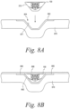
- Figures 8A-8D are cross-sectional end views illustrating various stages of a method for forming a composite part 800 using the mandrel 100 according to an example.
- the composite part 800 can be a hat-shaped stringer 802 co-cured to a fuselage skin 808; however, the composite part 800 can have a different shape and/or configuration in other examples.
- the stringer 802 is positioned in a trough 876.
- the trough 876 includes a groove with a generally trapezoidal hat-shaped cross-section, which provides a form for shaping and/or supporting the stringer 802.
- the stringer 802 can include a plurality of layers of composite material in an example.
- the stringer 802 has an interior surface 877 that defines an interior space 804.
- the mandrel 100 is positioned in the interior space 804 of the stringer 802 in the expanded state so that the exterior surface 318 of the mandrel 100 is in supporting contact with the interior surfaces 877 of the stringer 802.
- the actuator 106 can be in the first position in the cavity 328 to configure the mandrel 100 in the expanded state.
- the mandrel 100 is in the expanded state while the mandrel 100 is positioned in the interior space 804; however, the mandrel 100 can be positioned in the interior space 804 in the contracted state and then expanded to the expanded state in the interior space 804 in other examples.
- Figure 8B shows the mandrel 100 positioned in the interior space 804 while the mandrel 100 is in the expanded state. As shown in Figure 8B , once the mandrel 100 is positioned in the interior space 804 of the stringer 802, a fuselage skin 808 is laminated over the trough 876, end flange sections 806 of the stringer 802, and the mandrel 100.
- the fuselage skin 808 is then co-cured with the stringer 802 by applying heat and pressure in an autoclaving or a similar process.
- co-curing causes the fuselage skin 808 to become bonded to the flange sections 806 of the stringer 802 and the exterior surface 318 of the mandrel 100.
- the exterior surface 318 of the mandrel 100 can facilitate maintaining the shape of the stringer 802 under compressive forces applied during co-curing.
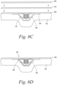
- Figure 8C illustrates an example step for co-curing the fuselage skin 808 and the stringer 802.
- Figure 8C shows co-curing by first positioning a caul sheet 878 over the fuselage skin 808, and positioning a vacuum bag 880 over the caul sheet 878 and the fuselage skin 808 to form a pressurized environment for autoclaving.
- the air space between the vacuum bag 880 and the fuselage skin 808 is then evacuated to apply an even pressure against the fuselage skin 808, the flange sections 806 of the stringer 802, and the exterior surface 318 of the mandrel 100.
- the fuselage skin 808 is then co-cured to the flange sections 806 of the stringer 802 at a curing temperature using an autoclave while under vacuum.
- Figure 8D illustrates a stage of the fabrication process after co-curing is completed.
- the fuselage skin 808 is separated from the caul sheet 878 and the vacuum bag 880, the mandrel 100 is contracted to the contracted state.
- the actuator 106 can be moved from the first position to the second position in the cavity 328 to contract the mandrel 100 from the expanded state to the contracted state.
- a gap 882 is present between the mandrel 100 and the stringer 802 as the size of the mandrel 100 in the contracted state is smaller than the size of the interior space 804.
- the smaller size of the mandrel 100 in the contracted state provides for easy removal of the mandrel 100 from the interior space 804 with relatively little risk of damage to the composite part 800.
- the mandrel 100 remained in the interior space 804 curing cure. This allows the mandrel 100 in the expanded state to support the composite part 800 against the pressures applied during the cure process.
- the mandrel 100 can be removed from the interior space 804 prior to cure. For instance, after positioning the fuselage skin 808 on the stringer 802, the mandrel 100 can be collapsed and withdrawn from the interior space 804 and then curing can be performed. This may be possible where an autoclave is used to apply equal pressure to the composite part 800 inside and outside of the interior space 804. By removing the mandrel 100 prior to cure, the mandrel 100 is not subjected to the increased temperatures and pressures of the cure process, which may extend the useful life of the mandrel 100.
- Figures 9A-9C illustrate an end view of various stage of a method for repairing a composite part 900.
- the composite part 900 is a hat-shaped stringer 902 co-cured to a fuselage skin 908.
- the composite part 900 also includes an interior space 904 between the stringer 902 and the fuselage skin 908.
- the composite part 900 includes a damaged area 990 on the fuselage skin 908.
- the damaged area 990 can be scarfed. Additionally, the mandrel 100 can be configured in the contracted state and then inserted into the interior space 904 of the composite part 900. The actuator 106 can be in the second position in the cavity 328 to configure the mandrel 100 in the contracted state.
- Figure 9B shows the mandrel 100, in the contracted state, inserted into the interior space 904 of the composite part 900.
- a gap 982 exists between the mandrel 100 and the composite part 900 as the size of the mandrel 100 in the contracted state is smaller than the size of the interior space 904.
- the smaller size of the mandrel 100 in the contracted state provides for easy insertion of the mandrel 100 in the interior space 904 with relatively little risk of further damage to the composite part 900.
- FIG. 9C shows the mandrel 100 in the interior space 904 after the mandrel 100 is expanded to the expanded state. As shown in Figure 9C , while the mandrel 100 is in the expanded state, the exterior surface 318 of the mandrel 100 is in supporting contact with the composite part 900. As such, the gap 982 is reduced or eliminated.
- repair operations can be performed on the composite part 900.
- an uncured material can be applied to the damaged area 990 and then cured.
- a vacuum bag 980 can be applied to the material at the damaged area 990 to cure the material and repair the composite part 900.
- the actuator 106 is moved from the first position to the second position to contract the mandrel 100 from the expanded state back to the contracted state as shown in Figure 9B .
- the gap 982 between the mandrel 100 and the composite part 900 is again present.
- the mandrel 100 can be easily removed from the interior space 904 with relatively little risk of damaging the composite part 900.
- Figure 10 depicts a flowchart of a method 1000 for repairing a part with a mandrel according to the present invention.
- the method 1000 can include configuring a mandrel in a contracted state at block 1010.
- the mandrel includes an upper-mandrel portion, a lower-mandrel portion, and a mid-mandrel portion between the upper-mandrel portion and the lower-mandrel portion.
- the mandrel also includes a cavity defined by the upper-mandrel portion, the lower-mandrel portion, and the mid-mandrel portion.
- the mandrel further includes an actuator, which is movable in the cavity between a first position in the cavity and a second position in the cavity, and an exterior surface defined by the upper-mandrel portion, the lower-mandrel portion, and the mid-mandrel portion.
- a perimeter of the exterior surface has a first length when the actuator is in the first position in the cavity and the perimeter has a second length when the actuator is in the second position in the cavity. The first length is greater than the second length such that the mandrel is in an expanded state when the actuator is in the first position and the mandrel is in the contracted state when the actuator is in the second position.
- the method 1000 includes inserting the mandrel, in the contracted state, in an interior space of a part. After inserting the mandrel in the interior space of the part at block 1012, the method 1000 includes moving the actuator from the second position to the first position to expand the mandrel from the contracted state to the expanded state at block 1014. While the mandrel is in the expanded state, the method includes repairing the part at block 1016. After repairing the part at block 1016, the method 1000 includes moving the actuator from the first position to the second position to contract the mandrel from the expanded state to the contracted state at block 1018. After contracting the mandrel at block 1018, the method 1000 includes removing the mandrel from the interior space of the part at block 1020.
- Figures 11-13 depict additional aspects of the method 1000.
- moving the actuator from the second position to the first position at block 1014 preferably includes urging the upper-mandrel portion, the lower-mandrel portion, and the mid-mandrel portion outwardly away from each other to expand the mandrel at block 1022.
- repairing the part at block 1016 preferably includes vacuum bagging to cure the part at block 1026.
- Figure 14 depicts a flowchart of a method 1100 of forming a part with a mandrel according to an example.
- the method 1100 preferably includes laying up a plurality of layers on a trough at block 1110.
- the method 1100 includes positioning a mandrel, in an expanded state, on the plurality of layers in the trough.
- a perimeter of the exterior surface has a first length when the actuator is in the first position in the cavity and the perimeter has a second length when the actuator is in the second position in the cavity.
- the first length is greater than the second length such that the mandrel is in an expanded state when the actuator is in the first position and the mandrel is in the contracted state when the actuator is in the second position.
- the method 1100 includes positioning a fuselage skin on the plurality of layers to form an interior space between the plurality of layers and the fuselage skin.
- the mandrel is in the interior space.
- the method 1100 includes co-curing the plurality of layers and the fuselage skin.
- the method 1100 includes moving the actuator from the first position to the second position to contract the mandrel from the expanded state to the contracted state. After contracting the mandrel at block 1118, the method 1100 includes removing the mandrel from the interior space at block 1120.
- Contracting and removing the mandrel at blocks 1118 and 1120 can be performed after co-curing the plurality of layers at block 1116. Contracting and removing the mandrel at blocks 1118 and 1120 can be performed before co-curing the plurality of layers at block 116.
- Figure 15 depicts additional aspects of the method 1100.
- the positioning the mandrel on the plurality of layers at block 1112 preferably includes bending the mandrel along a non-linear portion of the plurality of layers at block 1122.
- the upper-mandrel portion, the lower-mandrel portion, and the mid-mandrel portion may include a plurality of kerfs along a longitudinal axis extending from a first end of the mandrel to a second end of the mandrel to facilitate bending the mandrel at block 1022.
- the method 1000 and 1100 shown in Figures 10-15 depict examples of a method that can be used for the mandrel 100 shown in Figure 1-7 .
- Components of the mandrel 100 may be arranged to be adapted to, capable of, or suited for performing the functions, such as when operated in a specific manner.
- the methods 1000 and 1100 can include one or more operations, functions, or actions as illustrated in Figures 10-15 .
- the blocks of these Figures are illustrated in a sequential order, these blocks may also be performed in parallel, and/or in a different order than those described herein. Also, the various blocks may be combined into fewer blocks, divided into additional blocks, and/or removed based upon the desired implementation.
- the mandrel 100 can have a generally trapezoidal shape to conform to a correspondingly shaped interior space 204, 804, 904 of the composite part 200, 800, 900; however, the mandrel 100 can have a different shape to conform to differently shaped composite part in other examples.
- the term “substantially” it is meant that the recited characteristic, parameter, or value need not be achieved exactly, but that deviations or variations, including for example, tolerances, measurement error, measurement accuracy limitations and other factors known to skill in the art, may occur in amounts that do not preclude the effect the characteristic was intended to provide.
- the term “about” includes aspects of the recited characteristic, parameter, or value allowing for deviations or variations, including for example, tolerances, measurement error, measurement accuracy limitations and other factors known to skill in the art, and also ranges of the parameters extending a reasonable amount to provide for such variations.
Landscapes
- Engineering & Computer Science (AREA)
- Mechanical Engineering (AREA)
- Chemical & Material Sciences (AREA)
- Composite Materials (AREA)
- Architecture (AREA)
- Civil Engineering (AREA)
- Structural Engineering (AREA)
- Moulding By Coating Moulds (AREA)
- Moulds For Moulding Plastics Or The Like (AREA)
Claims (15)
- Mandrin (100) pour une pièce composite (200), comprenant :une partie de mandrin supérieur (310) ;une partie de mandrin inférieur (312) ;une partie de mandrin médian (314, 316) entre la partie de mandrin supérieur (310) et la partie de mandrin inférieur (312) ;une cavité (328) définie par la partie de mandrin supérieur (310), la partie de mandrin inférieur (312) et la partie de mandrin médian (314, 316), la cavité (328) comportant une première section (330) et une seconde section (332), dans lequel une largeur de la cavité (328) dans la première section (330) est inférieure à la largeur de la cavité (328) dans la seconde section (332) ;un actionneur (106) agencé dans la cavité (328) et mobile dans la cavité (328) entre une première position, dans lequel l'actionneur (106) est positionné dans la première section (330) de la cavité (328), et une seconde position, dans lequel l'actionneur (106) est positionné dans la seconde section (332) de la cavité (328) ; etune surface extérieure (318) définie par la partie de mandrin supérieur (310), la partie de mandrin inférieur (312) et la partie de mandrin médian (314, 316), dans lequel la surface extérieure (318) est conçue pour supporter la pièce composite (200),dans lequel un périmètre (560) de la surface extérieure (318) a une première longueur lorsque l'actionneur (106) est dans la première position dans la cavité (328) et le périmètre (560) a une seconde longueur lorsque l'actionneur (106) est dans la seconde position dans la cavité (328), etdans lequel la première longueur est supérieure à la seconde longueur de sorte que le mandrin (100) est dans un état étendu lorsque l'actionneur (106) est dans la première position et le mandrin (100) est dans un état de contracté lorsque l'actionneur (106) est dans la seconde position.
- Mandrin (100) selon la revendication 1, dans lequel la partie de mandrin supérieur (310), la partie de mandrin inférieur (312) et la partie de mandrin médian (314, 316) ont chacune une pluralité de saignées (320) le long d'un axe longitudinal (322) s'étendant d'une première extrémité (324) du mandrin (100) à une seconde extrémité (326) du mandrin (100).
- Mandrin (100) selon la revendication 2, dans lequel la pluralité de saignées (320) de la partie de mandrin médian (314, 316) s'étend de la partie de mandrin inférieur (312) à la partie de mandrin supérieur (310) à un angle dans une direction allant de la première extrémité (324) à la seconde extrémité (326).
- Mandrin (100) selon les revendications 1 à 3, dans lequel la partie de mandrin médian (314, 316) comprend une première partie de mandrin médian (314) et une seconde partie de mandrin médian (316) sur des côtés opposés de la cavité (328).
- Mandrin (100) selon la revendication 4, dans lequel l'actionneur (106) pousse la première partie de mandrin médian (314) et la seconde partie de mandrin médian (316) vers l'extérieur en les éloignant l'une de l'autre tandis que l'actionneur (106) se déplace de la seconde position à la première position, et
dans lequel la première partie de mandrin médian (314) et la seconde partie de mandrin médian (316) poussent la partie de mandrin supérieur (310) vers le haut en l'éloignant de la partie de mandrin inférieur (312) en réponse à l'actionneur (106) poussant la première partie de mandrin médian (314) et la seconde partie de mandrin médian (316) vers l'extérieur. - Mandrin (100) selon la revendication 5, dans lequel la partie de mandrin supérieur (310) a une surface inférieure (662) qui vient en prise avec une première surface supérieure (664) de la première partie de mandrin médian (314) et avec une seconde surface supérieure (666) de la seconde partie de mandrin médian (316), etdans lequel la première surface supérieure (664), la seconde surface supérieure (666) et la surface inférieure (662) ont chacune un profil incliné,dans lequel la mise en prise de la surface inférieure (662) avec la première surface supérieure (664) et la seconde surface supérieure (666) pousse la partie de mandrin supérieur (310) vers le haut en réponse à l'actionneur (106) poussant la première partie de mandrin médian (314) et la seconde partie de mandrin médian (316) vers l'extérieur.
- Mandrin (100) selon les revendications 5 à 6, dans lequel la première partie de mandrin médian (314) et la seconde partie de mandrin médian (316) poussent la partie de mandrin inférieur (312) vers le bas en l'éloignant de la partie de mandrin supérieur (310) en réponse à l'actionneur (106) poussant la première partie de mandrin médian (314) et la seconde partie de mandrin médian (316) vers l'extérieur.
- Mandrin (100) selon les revendications 1 à 7, dans lequel la cavité (328) comprend une première section (330) et une seconde section (332), et
dans lequel une largeur de la cavité (328) dans la première section (330) est inférieure à la largeur de la cavité (328) dans la seconde section (332). - Mandrin (100) selon la revendication 8, dans lequel une surface extérieure (446) de l'actionneur (106) a une largeur qui est inférieure à la largeur de la cavité (328) dans la seconde section (332) et supérieure à la largeur de la cavité (328) dans la première section (330).
- Mandrin (100) selon les revendications 1 à 9, comprenant en outre :une pluralité de saillies de guidage (336) s'étendant dans la cavité (328) à partir de la partie de mandrin supérieur (310), de la partie de mandrin médian (314, 316) et de la partie de mandrin inférieur (312) ; etune pluralité de fentes de guidage (448) sur l'actionneur (106),dans lequel chacune parmi la pluralité de fentes de guidage (448) reçoit une respective parmi la pluralité de saillies de guidage (336) pour guider le mouvement de l'actionneur (106) entre la première position et la seconde position, dans lequel la pluralité de saillies de guidage (336) et la pluralité de fentes de guidage (448) ont éventuellement une forme de T.
- Mandrin (100) selon les revendications 1 à 10, dans lequel l'actionneur (106) comprend une pluralité de segments (106A, 106B, 106C, 106D) accouplés les uns aux autres par une pluralité de liaisons (456) pour permettre à l'actionneur (106) de se plier.
- Procédé de réparation d'une pièce (200) avec un mandrin (100), comprenant :
la conception d'un mandrin (100) dans un état contracté, le mandrin (100) comprenant :une partie de mandrin supérieur (310),une partie de mandrin inférieur (312),une partie de mandrin médian (314, 316) entre la partie de mandrin supérieur (310) et la partie de mandrin inférieur (312),une cavité (328) définie par la partie de mandrin supérieur (310), la partie de mandrin inférieur (312) et la partie de mandrin médian (314, 316), la cavité (328) comportant une première section (330) et une seconde section (332), dans lequel une largeur de la cavité (328) dans la première section (330) est inférieure à la largeur de la cavité (328) dans la seconde section (332), etun actionneur (106) agencé dans la cavité (328) et mobile dans la cavité (328) entre une première position, dans lequel l'actionneur (106) est positionné dans la première section (330) de la cavité (328), et une seconde position, dans lequel l'actionneur (106) est positionné dans la seconde section (332) de la cavité (328) ;une surface extérieure (318) définie par la partie de mandrin supérieur (310), la partie de mandrin inférieur (312) et la partie de mandrin médian (314, 316),dans lequel un périmètre (560) de la surface extérieure (318) a une première longueur lorsque l'actionneur (106) est dans la première position dans la cavité (328) et le périmètre (560) a une seconde longueur lorsque l'actionneur (106) est dans la seconde position dans la cavité (328), etdans lequel la première longueur est supérieure à la seconde longueur de sorte que le mandrin (100) est dans un état étendu lorsque l'actionneur (106) est dans la première position et le mandrin (100) est à l'état contracté lorsque l'actionneur (106) est dans la seconde position ;l'insertion du mandrin (100), à l'état contracté, dans un espace intérieur (204) d'une pièce (200) ;après l'insertion du mandrin (100) dans l'espace intérieur (204) de la pièce, le déplacement de l'actionneur (106) de la seconde position à la première position pour étendre le mandrin (100) de l'état contracté à l'état étendu ;pendant que le mandrin (100) est à l'état étendu, la réparation de la pièce (200) ;après réparation de la pièce (200), le déplacement de l'actionneur (106) de la première position à la seconde position pour contracter le mandrin (100) de l'état étendu à l'état contracté ; etaprès contraction du mandrin (100), le retrait du mandrin (100) de l'espace intérieur (204) de la pièce (200). - Procédé selon la revendication 12, dans lequel le déplacement de l'actionneur (106) de la seconde position à la première position consiste à pousser la partie de mandrin supérieur (310), la partie de mandrin inférieur (312) et la partie de mandrin médian (314, 316) vers l'extérieur en les éloignant l'une de l'autre afin d'étendre le mandrin (100).
- Procédé selon les revendications 12 à 13, dans lequel l'insertion du mandrin (100) dans l'espace intérieur (204) de la pièce (200) consiste à plier le mandrin (100) le long d'un contour arqué de la pièce (200),
dans lequel la partie de mandrin supérieur (310), la partie de mandrin inférieur (312) et la partie de mandrin médian (314, 316) comprennent une pluralité de saignées (320) le long d'un axe longitudinal (322) s'étendant d'une première extrémité (324) du mandrin (100) à une seconde extrémité (326) du mandrin (100) pour faciliter le pliage du mandrin (100). - Procédé selon les revendications 12 à 14, dans lequel la réparation de la pièce (200) consiste à mettre sous vide pour durcir la pièce (200).
Applications Claiming Priority (1)
| Application Number | Priority Date | Filing Date | Title |
|---|---|---|---|
| US15/415,466 US10906210B2 (en) | 2017-01-25 | 2017-01-25 | Mandrel for composite part fabrication and repair |
Publications (2)
| Publication Number | Publication Date |
|---|---|
| EP3354448A1 EP3354448A1 (fr) | 2018-08-01 |
| EP3354448B1 true EP3354448B1 (fr) | 2024-06-26 |
Family
ID=60480201
Family Applications (1)
| Application Number | Title | Priority Date | Filing Date |
|---|---|---|---|
| EP17203705.3A Active EP3354448B1 (fr) | 2017-01-25 | 2017-11-27 | Mandrin pour la fabrication et la réparation de pièces composites |
Country Status (4)
| Country | Link |
|---|---|
| US (1) | US10906210B2 (fr) |
| EP (1) | EP3354448B1 (fr) |
| CN (1) | CN108340594B (fr) |
| SG (1) | SG10201709858VA (fr) |
Families Citing this family (5)
| Publication number | Priority date | Publication date | Assignee | Title |
|---|---|---|---|---|
| US20210299958A1 (en) * | 2020-03-28 | 2021-09-30 | Karl Joseph Dodds Gifford | Shrinkable platform for 3D printer |
| JP7261356B2 (ja) * | 2020-04-13 | 2023-04-19 | 川崎重工業株式会社 | 中子及び構造体の成形方法 |
| US12049047B2 (en) * | 2020-06-17 | 2024-07-30 | Mitsubishi Heavy Industries, Ltd. | Jig and composite material processing method |
| ES2974180T3 (es) * | 2021-07-29 | 2024-06-26 | Airbus Operations Slu | Dispositivo que comprende múltiples mandriles longitudinales que forman un molde para fabricar una pieza compuesta |
| FR3159546B1 (fr) * | 2024-02-28 | 2026-01-09 | Loiretech Ingenierie | Noyau pour le moulage d’un profilé composite creux et procédé de moulage utilisant un tel noyau |
Citations (1)
| Publication number | Priority date | Publication date | Assignee | Title |
|---|---|---|---|---|
| WO2007148301A2 (fr) * | 2006-06-23 | 2007-12-27 | Alenia Aeronautica S.P.A. | Appareil et procédé de fabrication d'un tronçon de fuselage |
Family Cites Families (20)
| Publication number | Priority date | Publication date | Assignee | Title |
|---|---|---|---|---|
| US2460325A (en) | 1945-06-23 | 1949-02-01 | Mercer L Whitson | Expansible mandrel |
| US4310138A (en) | 1980-06-18 | 1982-01-12 | Johnston George S | Self-supporting shrinking mandrel |
| JPS6044055B2 (ja) | 1982-06-28 | 1985-10-01 | 日本鋼管株式会社 | 管の扁平化防止装置 |
| US5580502A (en) * | 1995-03-23 | 1996-12-03 | Sikorsky Aircraft Corporation | Method of fabricating a composite article having an integral, co-cured composite stiffening member |
| US7357166B2 (en) | 2004-11-24 | 2008-04-15 | The Boeing Company | Flexible mandrel for highly contoured composite stringer |
| US7500494B2 (en) * | 2004-12-03 | 2009-03-10 | Illinois Tool Works Inc. | System and method for pipe repair |
| US8715560B2 (en) * | 2005-11-10 | 2014-05-06 | The Boeing Company | Method to control thickness in composite parts cured on closed angle tool |
| US8430984B2 (en) | 2010-05-11 | 2013-04-30 | The Boeing Company | Collapsible mandrel employing reinforced fluoroelastomeric bladder |
| US8795567B2 (en) * | 2010-09-23 | 2014-08-05 | The Boeing Company | Method for fabricating highly contoured composite stiffeners with reduced wrinkling |
| GB201116476D0 (en) * | 2011-09-26 | 2011-11-09 | Rolls Royce Plc | Mandrel for forming a component |
| DE102012000564B4 (de) | 2012-01-16 | 2015-02-19 | Airbus Operations Gmbh | Urformwerkzeug und Verfahren für die Fertigung eines aus faserverstärktem Kunststoff bestehenden aerodynamisch geformten Luftfahrzeugbauteils |
| ITTO20120284A1 (it) | 2012-03-30 | 2013-10-01 | Alenia Aermacchi Spa | Sistema azionamento settori appartenenti ad un dispositivo per la realizzazione di una sezione di fusoliera di un aereo |
| US9272767B2 (en) * | 2013-04-19 | 2016-03-01 | The Boeing Company | Compacting uncured composite members on contoured mandrel surfaces |
| US9352514B2 (en) | 2013-06-19 | 2016-05-31 | The Boeing Company | Fuselage mandrel insert and method |
| WO2015036940A1 (fr) * | 2013-09-10 | 2015-03-19 | Short Brothers Plc | Procédé de formation d'un élément composite et ensemble correspondant |
| US9475569B2 (en) | 2013-10-29 | 2016-10-25 | Gulfstream Aerospace Corporation | Methods for manufacturing an i-stringer of an aircraft and devices for use in such methods |
| FR3018719B1 (fr) | 2014-03-24 | 2016-04-29 | Airbus Operations Sas | Procede de consolidation d'elements en materiau composite pour former une piece en materiau composite comprenant une cavite debouchante et noyau utilise pour la mise en oeuvre dudit procede |
| US9724848B2 (en) | 2014-07-03 | 2017-08-08 | The Boeing Company | Collapsible, coiled mandrel |
| US10800111B2 (en) * | 2015-06-16 | 2020-10-13 | The Boeing Company | Composite structure fabrication systems and methods |
| US10328611B2 (en) | 2015-10-09 | 2019-06-25 | The Boeing Company | Mechanical support tooling and/or mandrel for composite part curing |
-
2017
- 2017-01-25 US US15/415,466 patent/US10906210B2/en active Active
- 2017-11-27 EP EP17203705.3A patent/EP3354448B1/fr active Active
- 2017-11-29 SG SG10201709858VA patent/SG10201709858VA/en unknown
- 2017-12-11 CN CN201711315637.XA patent/CN108340594B/zh active Active
Patent Citations (1)
| Publication number | Priority date | Publication date | Assignee | Title |
|---|---|---|---|---|
| WO2007148301A2 (fr) * | 2006-06-23 | 2007-12-27 | Alenia Aeronautica S.P.A. | Appareil et procédé de fabrication d'un tronçon de fuselage |
Also Published As
| Publication number | Publication date |
|---|---|
| CN108340594B (zh) | 2021-10-22 |
| US20180207840A1 (en) | 2018-07-26 |
| EP3354448A1 (fr) | 2018-08-01 |
| SG10201709858VA (en) | 2018-08-30 |
| CN108340594A (zh) | 2018-07-31 |
| US10906210B2 (en) | 2021-02-02 |
Similar Documents
| Publication | Publication Date | Title |
|---|---|---|
| US10889028B2 (en) | Mechanical support tooling and/or mandrel for composite part curing | |
| EP3354448B1 (fr) | Mandrin pour la fabrication et la réparation de pièces composites | |
| US8877114B2 (en) | Method for removing a SMP apparatus from a cured composite part | |
| US8815145B2 (en) | Methods and systems for fabricating composite stiffeners with a rigid/malleable SMP apparatus | |
| EP2637832B1 (fr) | Procédés et systèmes pour la co-liaison ou le co-durcissement de pièces composites à l'aide d'un appareil à polymère à mémoire de forme rigide/malléable | |
| US10059041B2 (en) | Multi-state bladder for manufacture of composite material | |
| US8734703B2 (en) | Methods and systems for fabricating composite parts using a SMP apparatus as a rigid lay-up tool and bladder | |
| US20190210253A1 (en) | Electromagnetic Support Tooling for Composite Part Curing | |
| US11220027B2 (en) | Mandrel for processing a composite part and method for fabricating a composite part | |
| US9827720B2 (en) | Multi-state bladder for manufacture of composite material | |
| US11964410B2 (en) | Multi-segment mandrel for processing a composite part and method for fabricating a composite part | |
| US11478958B2 (en) | Multi-component mandrel for processing a composite part and method for fabricating a composite part | |
| CA2808926A1 (fr) | Procedes et systemes pour former des pieces composites integrees avec un appareil a polymere a memoire de forme |
Legal Events
| Date | Code | Title | Description |
|---|---|---|---|
| PUAI | Public reference made under article 153(3) epc to a published international application that has entered the european phase |
Free format text: ORIGINAL CODE: 0009012 |
|
| STAA | Information on the status of an ep patent application or granted ep patent |
Free format text: STATUS: REQUEST FOR EXAMINATION WAS MADE |
|
| 17P | Request for examination filed |
Effective date: 20171127 |
|
| AK | Designated contracting states |
Kind code of ref document: A1 Designated state(s): AL AT BE BG CH CY CZ DE DK EE ES FI FR GB GR HR HU IE IS IT LI LT LU LV MC MK MT NL NO PL PT RO RS SE SI SK SM TR |
|
| AX | Request for extension of the european patent |
Extension state: BA ME |
|
| STAA | Information on the status of an ep patent application or granted ep patent |
Free format text: STATUS: EXAMINATION IS IN PROGRESS |
|
| 17Q | First examination report despatched |
Effective date: 20201202 |
|
| RAP3 | Party data changed (applicant data changed or rights of an application transferred) |
Owner name: THE BOEING COMPANY |
|
| GRAP | Despatch of communication of intention to grant a patent |
Free format text: ORIGINAL CODE: EPIDOSNIGR1 |
|
| STAA | Information on the status of an ep patent application or granted ep patent |
Free format text: STATUS: GRANT OF PATENT IS INTENDED |
|
| INTG | Intention to grant announced |
Effective date: 20240125 |
|
| GRAS | Grant fee paid |
Free format text: ORIGINAL CODE: EPIDOSNIGR3 |
|
| GRAA | (expected) grant |
Free format text: ORIGINAL CODE: 0009210 |
|
| STAA | Information on the status of an ep patent application or granted ep patent |
Free format text: STATUS: THE PATENT HAS BEEN GRANTED |
|
| AK | Designated contracting states |
Kind code of ref document: B1 Designated state(s): AL AT BE BG CH CY CZ DE DK EE ES FI FR GB GR HR HU IE IS IT LI LT LU LV MC MK MT NL NO PL PT RO RS SE SI SK SM TR |
|
| REG | Reference to a national code |
Ref country code: GB Ref legal event code: FG4D |
|
| REG | Reference to a national code |
Ref country code: CH Ref legal event code: EP |
|
| REG | Reference to a national code |
Ref country code: DE Ref legal event code: R096 Ref document number: 602017082791 Country of ref document: DE |
|
| P01 | Opt-out of the competence of the unified patent court (upc) registered |
Free format text: CASE NUMBER: APP_36010/2024 Effective date: 20240617 |
|
| PG25 | Lapsed in a contracting state [announced via postgrant information from national office to epo] |
Ref country code: BG Free format text: LAPSE BECAUSE OF FAILURE TO SUBMIT A TRANSLATION OF THE DESCRIPTION OR TO PAY THE FEE WITHIN THE PRESCRIBED TIME-LIMIT Effective date: 20240626 |
|
| PG25 | Lapsed in a contracting state [announced via postgrant information from national office to epo] |
Ref country code: FI Free format text: LAPSE BECAUSE OF FAILURE TO SUBMIT A TRANSLATION OF THE DESCRIPTION OR TO PAY THE FEE WITHIN THE PRESCRIBED TIME-LIMIT Effective date: 20240626 Ref country code: HR Free format text: LAPSE BECAUSE OF FAILURE TO SUBMIT A TRANSLATION OF THE DESCRIPTION OR TO PAY THE FEE WITHIN THE PRESCRIBED TIME-LIMIT Effective date: 20240626 |
|
| REG | Reference to a national code |
Ref country code: LT Ref legal event code: MG9D |
|
| PG25 | Lapsed in a contracting state [announced via postgrant information from national office to epo] |
Ref country code: GR Free format text: LAPSE BECAUSE OF FAILURE TO SUBMIT A TRANSLATION OF THE DESCRIPTION OR TO PAY THE FEE WITHIN THE PRESCRIBED TIME-LIMIT Effective date: 20240927 |
|
| PG25 | Lapsed in a contracting state [announced via postgrant information from national office to epo] |
Ref country code: LV Free format text: LAPSE BECAUSE OF FAILURE TO SUBMIT A TRANSLATION OF THE DESCRIPTION OR TO PAY THE FEE WITHIN THE PRESCRIBED TIME-LIMIT Effective date: 20240626 |
|
| REG | Reference to a national code |
Ref country code: NL Ref legal event code: MP Effective date: 20240626 |
|
| PG25 | Lapsed in a contracting state [announced via postgrant information from national office to epo] |
Ref country code: NO Free format text: LAPSE BECAUSE OF FAILURE TO SUBMIT A TRANSLATION OF THE DESCRIPTION OR TO PAY THE FEE WITHIN THE PRESCRIBED TIME-LIMIT Effective date: 20240926 Ref country code: LV Free format text: LAPSE BECAUSE OF FAILURE TO SUBMIT A TRANSLATION OF THE DESCRIPTION OR TO PAY THE FEE WITHIN THE PRESCRIBED TIME-LIMIT Effective date: 20240626 Ref country code: HR Free format text: LAPSE BECAUSE OF FAILURE TO SUBMIT A TRANSLATION OF THE DESCRIPTION OR TO PAY THE FEE WITHIN THE PRESCRIBED TIME-LIMIT Effective date: 20240626 Ref country code: GR Free format text: LAPSE BECAUSE OF FAILURE TO SUBMIT A TRANSLATION OF THE DESCRIPTION OR TO PAY THE FEE WITHIN THE PRESCRIBED TIME-LIMIT Effective date: 20240927 Ref country code: FI Free format text: LAPSE BECAUSE OF FAILURE TO SUBMIT A TRANSLATION OF THE DESCRIPTION OR TO PAY THE FEE WITHIN THE PRESCRIBED TIME-LIMIT Effective date: 20240626 Ref country code: BG Free format text: LAPSE BECAUSE OF FAILURE TO SUBMIT A TRANSLATION OF THE DESCRIPTION OR TO PAY THE FEE WITHIN THE PRESCRIBED TIME-LIMIT Effective date: 20240626 Ref country code: RS Free format text: LAPSE BECAUSE OF FAILURE TO SUBMIT A TRANSLATION OF THE DESCRIPTION OR TO PAY THE FEE WITHIN THE PRESCRIBED TIME-LIMIT Effective date: 20240926 |
|
| PG25 | Lapsed in a contracting state [announced via postgrant information from national office to epo] |
Ref country code: NL Free format text: LAPSE BECAUSE OF FAILURE TO SUBMIT A TRANSLATION OF THE DESCRIPTION OR TO PAY THE FEE WITHIN THE PRESCRIBED TIME-LIMIT Effective date: 20240626 |
|
| REG | Reference to a national code |
Ref country code: AT Ref legal event code: MK05 Ref document number: 1697370 Country of ref document: AT Kind code of ref document: T Effective date: 20240626 |
|
| PG25 | Lapsed in a contracting state [announced via postgrant information from national office to epo] |
Ref country code: NL Free format text: LAPSE BECAUSE OF FAILURE TO SUBMIT A TRANSLATION OF THE DESCRIPTION OR TO PAY THE FEE WITHIN THE PRESCRIBED TIME-LIMIT Effective date: 20240626 |
|
| PG25 | Lapsed in a contracting state [announced via postgrant information from national office to epo] |
Ref country code: PT Free format text: LAPSE BECAUSE OF FAILURE TO SUBMIT A TRANSLATION OF THE DESCRIPTION OR TO PAY THE FEE WITHIN THE PRESCRIBED TIME-LIMIT Effective date: 20241028 |
|
| PG25 | Lapsed in a contracting state [announced via postgrant information from national office to epo] |
Ref country code: PT Free format text: LAPSE BECAUSE OF FAILURE TO SUBMIT A TRANSLATION OF THE DESCRIPTION OR TO PAY THE FEE WITHIN THE PRESCRIBED TIME-LIMIT Effective date: 20241028 |
|
| PG25 | Lapsed in a contracting state [announced via postgrant information from national office to epo] |
Ref country code: PL Free format text: LAPSE BECAUSE OF FAILURE TO SUBMIT A TRANSLATION OF THE DESCRIPTION OR TO PAY THE FEE WITHIN THE PRESCRIBED TIME-LIMIT Effective date: 20240626 |
|
| PG25 | Lapsed in a contracting state [announced via postgrant information from national office to epo] |
Ref country code: EE Free format text: LAPSE BECAUSE OF FAILURE TO SUBMIT A TRANSLATION OF THE DESCRIPTION OR TO PAY THE FEE WITHIN THE PRESCRIBED TIME-LIMIT Effective date: 20240626 |
|
| PG25 | Lapsed in a contracting state [announced via postgrant information from national office to epo] |
Ref country code: AT Free format text: LAPSE BECAUSE OF FAILURE TO SUBMIT A TRANSLATION OF THE DESCRIPTION OR TO PAY THE FEE WITHIN THE PRESCRIBED TIME-LIMIT Effective date: 20240626 Ref country code: IS Free format text: LAPSE BECAUSE OF FAILURE TO SUBMIT A TRANSLATION OF THE DESCRIPTION OR TO PAY THE FEE WITHIN THE PRESCRIBED TIME-LIMIT Effective date: 20241026 |
|
| PG25 | Lapsed in a contracting state [announced via postgrant information from national office to epo] |
Ref country code: CZ Free format text: LAPSE BECAUSE OF FAILURE TO SUBMIT A TRANSLATION OF THE DESCRIPTION OR TO PAY THE FEE WITHIN THE PRESCRIBED TIME-LIMIT Effective date: 20240626 |
|
| PG25 | Lapsed in a contracting state [announced via postgrant information from national office to epo] |
Ref country code: RO Free format text: LAPSE BECAUSE OF FAILURE TO SUBMIT A TRANSLATION OF THE DESCRIPTION OR TO PAY THE FEE WITHIN THE PRESCRIBED TIME-LIMIT Effective date: 20240626 Ref country code: SK Free format text: LAPSE BECAUSE OF FAILURE TO SUBMIT A TRANSLATION OF THE DESCRIPTION OR TO PAY THE FEE WITHIN THE PRESCRIBED TIME-LIMIT Effective date: 20240626 |
|
| PG25 | Lapsed in a contracting state [announced via postgrant information from national office to epo] |
Ref country code: ES Free format text: LAPSE BECAUSE OF FAILURE TO SUBMIT A TRANSLATION OF THE DESCRIPTION OR TO PAY THE FEE WITHIN THE PRESCRIBED TIME-LIMIT Effective date: 20240626 Ref country code: SM Free format text: LAPSE BECAUSE OF FAILURE TO SUBMIT A TRANSLATION OF THE DESCRIPTION OR TO PAY THE FEE WITHIN THE PRESCRIBED TIME-LIMIT Effective date: 20240626 |
|
| PG25 | Lapsed in a contracting state [announced via postgrant information from national office to epo] |
Ref country code: SM Free format text: LAPSE BECAUSE OF FAILURE TO SUBMIT A TRANSLATION OF THE DESCRIPTION OR TO PAY THE FEE WITHIN THE PRESCRIBED TIME-LIMIT Effective date: 20240626 Ref country code: SK Free format text: LAPSE BECAUSE OF FAILURE TO SUBMIT A TRANSLATION OF THE DESCRIPTION OR TO PAY THE FEE WITHIN THE PRESCRIBED TIME-LIMIT Effective date: 20240626 Ref country code: RO Free format text: LAPSE BECAUSE OF FAILURE TO SUBMIT A TRANSLATION OF THE DESCRIPTION OR TO PAY THE FEE WITHIN THE PRESCRIBED TIME-LIMIT Effective date: 20240626 Ref country code: PL Free format text: LAPSE BECAUSE OF FAILURE TO SUBMIT A TRANSLATION OF THE DESCRIPTION OR TO PAY THE FEE WITHIN THE PRESCRIBED TIME-LIMIT Effective date: 20240626 Ref country code: IS Free format text: LAPSE BECAUSE OF FAILURE TO SUBMIT A TRANSLATION OF THE DESCRIPTION OR TO PAY THE FEE WITHIN THE PRESCRIBED TIME-LIMIT Effective date: 20241026 Ref country code: ES Free format text: LAPSE BECAUSE OF FAILURE TO SUBMIT A TRANSLATION OF THE DESCRIPTION OR TO PAY THE FEE WITHIN THE PRESCRIBED TIME-LIMIT Effective date: 20240626 Ref country code: EE Free format text: LAPSE BECAUSE OF FAILURE TO SUBMIT A TRANSLATION OF THE DESCRIPTION OR TO PAY THE FEE WITHIN THE PRESCRIBED TIME-LIMIT Effective date: 20240626 Ref country code: CZ Free format text: LAPSE BECAUSE OF FAILURE TO SUBMIT A TRANSLATION OF THE DESCRIPTION OR TO PAY THE FEE WITHIN THE PRESCRIBED TIME-LIMIT Effective date: 20240626 Ref country code: AT Free format text: LAPSE BECAUSE OF FAILURE TO SUBMIT A TRANSLATION OF THE DESCRIPTION OR TO PAY THE FEE WITHIN THE PRESCRIBED TIME-LIMIT Effective date: 20240626 |
|
| PG25 | Lapsed in a contracting state [announced via postgrant information from national office to epo] |
Ref country code: IT Free format text: LAPSE BECAUSE OF FAILURE TO SUBMIT A TRANSLATION OF THE DESCRIPTION OR TO PAY THE FEE WITHIN THE PRESCRIBED TIME-LIMIT Effective date: 20240626 |
|
| REG | Reference to a national code |
Ref country code: DE Ref legal event code: R097 Ref document number: 602017082791 Country of ref document: DE |
|
| PG25 | Lapsed in a contracting state [announced via postgrant information from national office to epo] |
Ref country code: DK Free format text: LAPSE BECAUSE OF FAILURE TO SUBMIT A TRANSLATION OF THE DESCRIPTION OR TO PAY THE FEE WITHIN THE PRESCRIBED TIME-LIMIT Effective date: 20240626 |
|
| PLBE | No opposition filed within time limit |
Free format text: ORIGINAL CODE: 0009261 |
|
| STAA | Information on the status of an ep patent application or granted ep patent |
Free format text: STATUS: NO OPPOSITION FILED WITHIN TIME LIMIT |
|
| 26N | No opposition filed |
Effective date: 20250327 |
|
| REG | Reference to a national code |
Ref country code: CH Ref legal event code: PL |
|
| PG25 | Lapsed in a contracting state [announced via postgrant information from national office to epo] |
Ref country code: MC Free format text: LAPSE BECAUSE OF FAILURE TO SUBMIT A TRANSLATION OF THE DESCRIPTION OR TO PAY THE FEE WITHIN THE PRESCRIBED TIME-LIMIT Effective date: 20240626 |
|
| PG25 | Lapsed in a contracting state [announced via postgrant information from national office to epo] |
Ref country code: LU Free format text: LAPSE BECAUSE OF NON-PAYMENT OF DUE FEES Effective date: 20241127 |
|
| REG | Reference to a national code |
Ref country code: CH Ref legal event code: PL |
|
| PG25 | Lapsed in a contracting state [announced via postgrant information from national office to epo] |
Ref country code: CH Free format text: LAPSE BECAUSE OF NON-PAYMENT OF DUE FEES Effective date: 20241130 |
|
| REG | Reference to a national code |
Ref country code: BE Ref legal event code: MM Effective date: 20241130 |
|
| PG25 | Lapsed in a contracting state [announced via postgrant information from national office to epo] |
Ref country code: SE Free format text: LAPSE BECAUSE OF FAILURE TO SUBMIT A TRANSLATION OF THE DESCRIPTION OR TO PAY THE FEE WITHIN THE PRESCRIBED TIME-LIMIT Effective date: 20240626 |
|
| PG25 | Lapsed in a contracting state [announced via postgrant information from national office to epo] |
Ref country code: BE Free format text: LAPSE BECAUSE OF NON-PAYMENT OF DUE FEES Effective date: 20241130 |
|
| PG25 | Lapsed in a contracting state [announced via postgrant information from national office to epo] |
Ref country code: IE Free format text: LAPSE BECAUSE OF NON-PAYMENT OF DUE FEES Effective date: 20241127 |
|
| PGFP | Annual fee paid to national office [announced via postgrant information from national office to epo] |
Ref country code: DE Payment date: 20251128 Year of fee payment: 9 |
|
| PGFP | Annual fee paid to national office [announced via postgrant information from national office to epo] |
Ref country code: GB Payment date: 20251127 Year of fee payment: 9 |
|
| PGFP | Annual fee paid to national office [announced via postgrant information from national office to epo] |
Ref country code: FR Payment date: 20251125 Year of fee payment: 9 |
|
| PG25 | Lapsed in a contracting state [announced via postgrant information from national office to epo] |
Ref country code: HU Free format text: LAPSE BECAUSE OF FAILURE TO SUBMIT A TRANSLATION OF THE DESCRIPTION OR TO PAY THE FEE WITHIN THE PRESCRIBED TIME-LIMIT; INVALID AB INITIO Effective date: 20171127 |
|
| PG25 | Lapsed in a contracting state [announced via postgrant information from national office to epo] |
Ref country code: CY Free format text: LAPSE BECAUSE OF FAILURE TO SUBMIT A TRANSLATION OF THE DESCRIPTION OR TO PAY THE FEE WITHIN THE PRESCRIBED TIME-LIMIT; INVALID AB INITIO Effective date: 20171127 |