EP3354460A1 - Procédé de gravure d'une plaque d'impression en creux - Google Patents
Procédé de gravure d'une plaque d'impression en creux Download PDFInfo
- Publication number
- EP3354460A1 EP3354460A1 EP18150168.5A EP18150168A EP3354460A1 EP 3354460 A1 EP3354460 A1 EP 3354460A1 EP 18150168 A EP18150168 A EP 18150168A EP 3354460 A1 EP3354460 A1 EP 3354460A1
- Authority
- EP
- European Patent Office
- Prior art keywords
- engraving
- layers
- engraved
- laser
- intaglio
- Prior art date
- Legal status (The legal status is an assumption and is not a legal conclusion. Google has not performed a legal analysis and makes no representation as to the accuracy of the status listed.)
- Granted
Links
Images


Classifications
-
- B—PERFORMING OPERATIONS; TRANSPORTING
- B41—PRINTING; LINING MACHINES; TYPEWRITERS; STAMPS
- B41C—PROCESSES FOR THE MANUFACTURE OR REPRODUCTION OF PRINTING SURFACES
- B41C1/00—Forme preparation
- B41C1/02—Engraving; Heads therefor
- B41C1/04—Engraving; Heads therefor using heads controlled by an electric information signal
- B41C1/05—Heat-generating engraving heads, e.g. laser beam, electron beam
-
- B—PERFORMING OPERATIONS; TRANSPORTING
- B23—MACHINE TOOLS; METAL-WORKING NOT OTHERWISE PROVIDED FOR
- B23K—SOLDERING OR UNSOLDERING; WELDING; CLADDING OR PLATING BY SOLDERING OR WELDING; CUTTING BY APPLYING HEAT LOCALLY, e.g. FLAME CUTTING; WORKING BY LASER BEAM
- B23K26/00—Working by laser beam, e.g. welding, cutting or boring
- B23K26/36—Removing material
-
- B—PERFORMING OPERATIONS; TRANSPORTING
- B41—PRINTING; LINING MACHINES; TYPEWRITERS; STAMPS
- B41N—PRINTING PLATES OR FOILS; MATERIALS FOR SURFACES USED IN PRINTING MACHINES FOR PRINTING, INKING, DAMPING, OR THE LIKE; PREPARING SUCH SURFACES FOR USE AND CONSERVING THEM
- B41N1/00—Printing plates or foils; Materials therefor
- B41N1/04—Printing plates or foils; Materials therefor metallic
- B41N1/06—Printing plates or foils; Materials therefor metallic for relief printing or intaglio printing
Definitions
- the invention relates to a method for engraving an Intaglio intaglio printing plate with a laser.
- Fig. 1 to 6 show various steps and illustrations of a preferred embodiment of a method for engraving an Intaglio intaglio printing plate 1 with a laser.
- Intaglio intaglio printing is a printing process using an engraved Intaglio intaglio printing plate 1, whereby the shape of the engraving is not only applied as a color to the sheets to be printed, but also results in a lasting and often palpable plastic deformation of the printed sheets Therefore Intaglio intaglio printing is often used as a security feature for security documents such as banknotes, stamps or securities.
- the laser beam of the laser is preferably directed by means of a controllable mirror system of the laser, wherein the mirror system is controlled by a control device.
- an impact of the laser beam of the laser on the Intaglio intaglio printing plate 1 can be controlled in a predeterminable manner by means of a shutter element, wherein the shutter element is controlled by the control device.
- a depth profile 2 of the intaglio intaglio printing plate 1 is produced by engraving a plurality of engraving layers 3 by means of the laser, wherein a desired engraving layer 5 is determined for each of the engraving layers 3 on the basis of a predetermined desired depth profile 4.
- the finished intaglio intaglio printing plate 1 has a three-dimensional depth profile 2, which is applied in the same way on the sheets to be printed during the printing process.
- a plurality of two-dimensional gravure layers 3 are removed in a blank of Intaglio intaglio printing plate 1 until the depth profile 2 of intaglio intaglio printing plate 1 is reached.
- the blank may originally have a flat surface.
- a predetermined desired depth profile 4 is created, which corresponds to the depth profile 2 to be reached. From the top 11 parallel sections of the desired depth profile 4, the target engraving layers 5 are then created.
- edges 6 of the regions 7 to be engraved of the desired gravure layers 5 flank angles are determined, wherein for each desired engraving layer 5 and each flank angle in this target engraving layer 5, a correction offset 8 is determined.
- the desired engraving layer 5 has two different types of regions, namely those regions 7 to be engraved, in which the laser is intended to remove material, and regions 13 which are not to be engraved and in which no ablation by the laser is to take place.
- the respective flank angle is determined based on the desired depth profile 4.
- the flank angle is in this case that angle which occupies the flank 12, to which the respective edge 6 belongs, to a plane of an upper side 11 of the Intaglio intaglio printing plate 1.
- the correction offset 8 is a size which is suitable for the correction of the aforementioned disturbances, for example the influence of the non-flatness of the already processed material, the narrowing channel and dust and material residues on the removal by the laser. It has been shown that two parameters are decisive for the determination of the correction offset 8, namely the extent of the material already removed there above, which emerges from the depth of the respective desired engraving layer 5, as well as the flank angle, in particular because of geometric influences the ablation capabilities of the laser increase with increasing flank angle.
- control engraving layers 9 are used to control the laser.
- the control engraving layers 9 are prepared from the target engraving layers 5 and represent a shape of the target engraving layers 5 corrected using the correction offset 8.
- a depth profile 2 of the intaglio intaglio printing plate 1 can be generated, which corresponds to the desired depth profile 4 comes very close. It can be provided that the control engraving layers 9 are used to control the control device of the laser.
- the intaglio intaglio printing plate 1 is used for producing a security document, since thereby reliable security features can be impressed on the security document in high quality.
- a Intaglio intaglio printing plate 1 consisting of metal, in particular brass, is engraved directly by the laser.
- Direct engraved in the context means that not first a so-called master engraved from a less stable material such as plastics, and this master is the final printing plate is molded, but the Intaglio intaglio printing plate 1 intended for printing is engraved directly from the laser.
- a processing step in the production of Intaglio intaglio printing plate 1 can be omitted, whereby the errors associated therewith can be avoided.
- Brass has the advantage that it is both easy to work with and, at the same time, the high mechanical stress of Intaglio intaglio printing has grown.
- a substantially flat Intaglio intaglio printing plate 1 is engraved.
- Such flat printing plates are particularly flexible in use.
- a pulse laser particularly preferably an ultrashort pulse laser
- Such pulsed lasers do not emit the laser beam continuously, but in the form of periodically recurring short pulses, wherein the instantaneous output power of the laser during the pulse is a multiple of the time-averaged output power of the laser.
- the mirror system of the laser is preferably moved in such a way that a laser beam of the laser is moved in substantially parallel lines 14 over the area 7 to be engraved during removal of the areas 7 of the respective control engraving layer 9 to be engraved.
- An area 7 to be engraved as area is therefore scanned by the laser similar to a hatching.
- Such an approach is exemplary in Fig. 6 shown.
- control engraving layers 9 are created using a computer-implemented method.
- the desired depth profile 4 can be present in particular in the form of a file in which the height information is created as digital data. From the desired depth profile 4 are then, together with the information of the intended removal depth of the individual gravure layers 3, the target engraving layer 5 is determined.
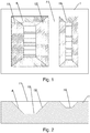
- Fig. 1 and 2 a preferred embodiment of a desired depth profile 4 with a first recess 15 and a second recess 16 is shown.
- Illustrated illustrations are greatly simplified and shown greatly distorted in terms of their size ratios, and serve only to better explain the individual process steps.
- the desired depth profile 4 is subdivided by computational sections parallel to the upper side 11 into a plurality of desired gravure layer 5 assigned to one of the gravure layers 3 in each case.
- the desired engraving layer 5 can subsequently be stored.
- the upper side 11 of the next engraving layer 3 may be the first engraving layer 17, wherein with increasing depth further gravure layers 18, 19, 20 are arranged.
- Fig. 3 illustrated preferred embodiment Fig. 1 and 2 This is the second engraving layer 18, the third engraving layer 19 and the fourth engraving layer 20.
- Fig. 3 It is shown how, in the preferred embodiment, the desired gravure layers 5 for the individual gravure layers 3 are determined from the desired depth profile 4. Where the respective engraving layer 3 intersects the flank 12, the edge 6 of the region 7 to be engraved is the respective desired gravure layer 5. The flank angle for the respective edge also emerges from the desired depth profile 4. In Fig. 4 is the target engraving layers 5 of the third engraving layer 19 from Fig. 3 shown.
- control engraving layers 9 are created.
- the edges 6 of the regions 7 to be engraved are adapted by the correction offset 8.
- the principle behind the correction offset 8 is that by corresponding enlargement of the regions 7 to be engraved, the effects which cause the engraved depth profile 2 deviates from the desired depth profile 4, be repealed.
- a value table is provided at correction offsets 8 for different flank angles and depths.
- a suitable correction offset 8 can easily be provided for each edge.
- calibration measurements may be made to determine the look-up table at correction offsets 8 for different flank angles and depths.
- depressions with different flank angles can preferably be made in a test specimen, preferably of the same material as Intaglio intaglio printing plate 1, by means of the laser engraved.
- the individual correction offset 8 can be determined by means of iterative methods at predetermined flank angles for predetermined depths.
- a plurality of discrete flank angles in a predetermined angular range can be used for the creation of the value table at correction offsets 8, wherein the individual discrete flank angles have a constant distance, preferably 5 °, from one another. If the flank angle of an edge 6 of a desired engraving layer 5 is between the discrete flank angle in the value table, an appropriate correction offset 8 can be interpolated.
- the flank angles may in particular be less than or equal to 70 °.
- flank angles are greater than or equal to 35 °.
- the table of values may particularly preferably have the correction offsets 8 for the flank angles 35 °, 40 °, 45 °, 50 °, 55 °, 60 °, 65 °, 70 ° and 75 °.
- a set of correction offsets 8 can be determined for each discrete flank angle.
- the correction offset 8 can also be calculated for a given flank angle and depth. The calculation can be made on the basis of parameters which can likewise be determined by measurements with different flank angles.
- the orientation of the edge relative to the direction of movement of the laser beam on the intaglio intaglio printing plate 1 is also taken into account when determining the correction offset 8. It has been found that slight differences result from whether the laser beam is substantially parallel or perpendicular to the edge 6.
- the removal depth of the individual gravure layers 3 from one another is determined on the basis of the existing flank angles in the desired depth profile 4.
- the removal depth is the distance between the individual neighboring ones Engraving layers 3.
- a low ablation depth is selected in order to avoid step formation in the depth profile, while larger ablation depths are preferably selected for only high flank angles.
- the removal depth can be adjusted by the power of the laser and / or the movement speed of the focal point 10 on the intaglio intaglio printing plate 1.
- the removal depth is constant, that is, does not change with depth.
- the power and the movement speed of the laser need not be varied.
- the power of the laser and / or the movement speed of the focal point 10 is kept constant on the intaglio intaglio printing plate 1.
- the desired depth profile 4 has only straight flanks 12.
- a straight flank means that the flank angle of the desired depth profile 4 remains constant over the depth, such as in Fig. 2 and 3 shown. This has the advantage that the deviation between the desired depth profile 4 and the actually engraved depth profile can be kept particularly low.
- flank angle of a flank 12 of the desired depth profile 4 varies over the depth.
- the result of the engraving can be improved, deviations are possible.
- the edge 6 has the same flank angle circumferentially.
- the edge 6 has different flank angles, for example when the Flank angle along the side is another than the front side.
- the desired depth profile 4 essentially has only a single flank angle.
- all flanks 12 of the desired depth profile 4 may have the same inclination.
- the correction offset 8 may in particular be a length.
- the regions 7 of the desired engraving layers 5 to be engraved are circumferentially enlarged by the respective correction offset 8 to produce the control engraving layers 9 at the edges 6.
- the correction offset 8 represents a length by which the edge 6 of the regions 7 to be engraved is displaced outwards, as a result of which the regions 7 to be engraved are enlarged.
- Fig. 5 the adapted edge 6 of the engraved area 7 of the control engraving layer 9 for the third engraving layer is shown by way of example.
- the original edge of the area to be engraved 7 of the target engraving layer 5 is shown by dashed lines.
- the correction offset 8 is shown as an arrow by whose amount the edge 6 has been increased.
- the region 7 to be engraved is enlarged at the respective section of the edge 6 by the respective correction offset 8.
- the areas 7 of the target engraving layers 5 to be engraved are reduced in circumference by half the diameter of a focal point 10 of the laser to produce the control engraving layers 9 at the edges 6.
- an effect can be corrected, which is caused by the finite extent of the focal point 10 of the laser, and which one would ensure that an engraved area is larger on each side by half a diameter of a focal point 10 of the laser than intended.
- This correction with respect to the finite extent of the focal point 10 of the laser is opposite to the correction by the correction offset.
- the diameter of the focal point 10 of the laser is kept constant.
- the diameter of the focal point 10 of the laser may preferably be between 10 ⁇ m and 30 ⁇ m, preferably between 15 ⁇ m and 25 ⁇ m.
- the correction offset 8 increases with the depth of the engraving layer 3. It has been shown that with increasing depth the required correction, and therefore also the size of the correction offset 8, increases.
- Fig. 3 2 shows the increase of the correction offset 8 for the preferred embodiment, wherein the correction offset 8 represents the distance between the edge 12 of the desired depth profile 4 and the dashed curve, which dashed curve corresponds to the edge 12 of the control gravure layers 9.
- the regions 7 to be engraved become larger and larger in comparison to the desired depth profile 4 serving as a template in order to obtain a depth profile corresponding to the desired depth profile 4.
- the correction offset 8 is substantially as large as half the diameter of the focal point 10 of the laser.
- the regions 7 to be engraved are reduced in the creation of the control engraving layers 9, while at depths of the engraving layer 3 greater the first depth, the regions 7 to be engraved are enlarged during the creation of the control engraving layers 9 become.
- regions 7 which are to be engraved and which are to be engraved are to be erased in the creation of the control engraving layers 9 outside of a region 7 to be engraved, of a control engraving layer 9 nearest to an upper side 11 of Intaglio intaglio printing plate 1.
- the control engraving layer 9 closest to the upper side 11 of Intaglio intaglio printing plate 1 is that of the first one Engraving layer 17. It is therefore checked whether a too serious area 7 of a depth in the control gravure layer 9 beyond the region to be engraved 7 lying on the top 11 control gravure layer 9, wherein the range beyond it is deleted. This can be the case with large flank angles. As a result, it can be prevented that, at high flank angles, the region 7 to be engraved of a gravure layer 3 located in the depth is removed by the correction offset 8 superficially beyond the border of the respective depression.
Landscapes
- Engineering & Computer Science (AREA)
- Physics & Mathematics (AREA)
- Optics & Photonics (AREA)
- Plasma & Fusion (AREA)
- Mechanical Engineering (AREA)
- Manufacturing & Machinery (AREA)
- Manufacture Or Reproduction Of Printing Formes (AREA)
Priority Applications (1)
| Application Number | Priority Date | Filing Date | Title |
|---|---|---|---|
| PL18150168T PL3354460T3 (pl) | 2017-01-30 | 2018-01-03 | Sposób grawerowania płyty drukowej wklęsłej |
Applications Claiming Priority (1)
| Application Number | Priority Date | Filing Date | Title |
|---|---|---|---|
| ATA50061/2017A AT519582B1 (de) | 2017-01-30 | 2017-01-30 | Verfahren zum gravieren einer intaglio-stichtiefdruckplatte |
Publications (2)
| Publication Number | Publication Date |
|---|---|
| EP3354460A1 true EP3354460A1 (fr) | 2018-08-01 |
| EP3354460B1 EP3354460B1 (fr) | 2019-08-07 |
Family
ID=60954859
Family Applications (1)
| Application Number | Title | Priority Date | Filing Date |
|---|---|---|---|
| EP18150168.5A Active EP3354460B1 (fr) | 2017-01-30 | 2018-01-03 | Procédé de gravure d'une plaque d'impression en creux |
Country Status (6)
| Country | Link |
|---|---|
| EP (1) | EP3354460B1 (fr) |
| AT (1) | AT519582B1 (fr) |
| ES (1) | ES2744539T3 (fr) |
| HU (1) | HUE044854T2 (fr) |
| PL (1) | PL3354460T3 (fr) |
| PT (1) | PT3354460T (fr) |
Cited By (1)
| Publication number | Priority date | Publication date | Assignee | Title |
|---|---|---|---|---|
| CN114589506A (zh) * | 2022-03-31 | 2022-06-07 | 上汽通用五菱汽车股份有限公司 | 一种假缝线模具加工工艺 |
Citations (3)
| Publication number | Priority date | Publication date | Assignee | Title |
|---|---|---|---|---|
| EP1580020A1 (fr) * | 2004-03-24 | 2005-09-28 | Kba-Giori S.A. | Plaque d'impression en creux |
| WO2006045128A1 (fr) * | 2004-10-28 | 2006-05-04 | Oesterreichische Banknoten- Und Sicherheitsdruck Gmbh | Dispositif pour graver des plaques d'impression |
| EP2743025A2 (fr) * | 2008-05-16 | 2014-06-18 | KBA-NotaSys SA | Procédé et système pour la fabrication de plaques d'impression en creux dans la production de papiers sécurisés |
Family Cites Families (2)
| Publication number | Priority date | Publication date | Assignee | Title |
|---|---|---|---|---|
| DE19916081A1 (de) * | 1999-04-09 | 2000-10-12 | Arges Ges Fuer Industrieplanun | Verfahren zum Kalibrieren einer Vorrichtung zur Bearbeitung von Werkstücken |
| HK1104419A2 (en) * | 2007-09-21 | 2008-01-11 | Adamberry Robert | Map pen |
-
2017
- 2017-01-30 AT ATA50061/2017A patent/AT519582B1/de active
-
2018
- 2018-01-03 EP EP18150168.5A patent/EP3354460B1/fr active Active
- 2018-01-03 HU HUE18150168 patent/HUE044854T2/hu unknown
- 2018-01-03 PT PT18150168T patent/PT3354460T/pt unknown
- 2018-01-03 PL PL18150168T patent/PL3354460T3/pl unknown
- 2018-01-03 ES ES18150168T patent/ES2744539T3/es active Active
Patent Citations (3)
| Publication number | Priority date | Publication date | Assignee | Title |
|---|---|---|---|---|
| EP1580020A1 (fr) * | 2004-03-24 | 2005-09-28 | Kba-Giori S.A. | Plaque d'impression en creux |
| WO2006045128A1 (fr) * | 2004-10-28 | 2006-05-04 | Oesterreichische Banknoten- Und Sicherheitsdruck Gmbh | Dispositif pour graver des plaques d'impression |
| EP2743025A2 (fr) * | 2008-05-16 | 2014-06-18 | KBA-NotaSys SA | Procédé et système pour la fabrication de plaques d'impression en creux dans la production de papiers sécurisés |
Cited By (1)
| Publication number | Priority date | Publication date | Assignee | Title |
|---|---|---|---|---|
| CN114589506A (zh) * | 2022-03-31 | 2022-06-07 | 上汽通用五菱汽车股份有限公司 | 一种假缝线模具加工工艺 |
Also Published As
| Publication number | Publication date |
|---|---|
| PT3354460T (pt) | 2019-09-19 |
| HUE044854T2 (hu) | 2019-11-28 |
| ES2744539T3 (es) | 2020-02-25 |
| EP3354460B1 (fr) | 2019-08-07 |
| AT519582A1 (de) | 2018-08-15 |
| PL3354460T3 (pl) | 2019-11-29 |
| AT519582B1 (de) | 2019-12-15 |
Similar Documents
| Publication | Publication Date | Title |
|---|---|---|
| DE102012106156B4 (de) | Verfahren zur Steuerung eines Werkzeuges | |
| EP3041637A1 (fr) | Procédé d'usinage d'une pièce au moyen d'un faisceau laser, outil laser, machine laser, et commande de machine | |
| EP3970900B1 (fr) | Procédé de génération d'une structure 3d par lithographie laser à dose d'exposition modifiée au niveau des sections de bord, ainsi que produit-programme informatique correspondant | |
| EP2164705B1 (fr) | Un procédé pour la fabrication d'un matériau continu sans couture pour les éléments de sécurité, un matériau continu sans couture pour les éléments de sécurité ainsi que des procédés pour la fabrication de cylindres d'impression ou d'estampage | |
| EP1667812B1 (fr) | Procede d'usinage d'une surface tridimensionnelle | |
| EP2873471B1 (fr) | Procédé et installation d'usinage laser pour réaliser un marquage indestructible sur une pièce | |
| EP0418768B1 (fr) | Matrice profilée et procédé pour sa fabrication | |
| DE102022129623A1 (de) | Verfahren zur Herstellung eines Werkzeugs, Werkzeug, Verfahren zur Bearbeitung eines Werkstücks, Werkstück | |
| DE102012006558B4 (de) | Verfahren zur Herstellung einer Flexodruckform | |
| DE202022106292U1 (de) | Werkzeug und Werkstück | |
| EP3354460B1 (fr) | Procédé de gravure d'une plaque d'impression en creux | |
| EP3229988A1 (fr) | Procédé de fabrication d'électrodes en feuille pour des condensateurs, électrodes en feuille et condensateurs pourvus desdites électrodes | |
| DE102005026968B4 (de) | Verfahren zum dauerhaften Aufbringen eines Graustufen-Bildes auf eine matte Oberfläche | |
| EP3739113B1 (fr) | Procédé et dispositif de fabrication d'un outil de filigranage | |
| EP4118048A1 (fr) | Procédé de mise en forme d'un substrat support pour un élément optique fonctionnel | |
| WO2024100118A1 (fr) | Procédé de fabrication d'un outil, outil, procédé d'usinage d'une pièce, pièce | |
| EP2561987A2 (fr) | Procédé de gravure d'une planche d'impression | |
| DE10345087A1 (de) | Verfahren zur schichtabtragenden 3-dimensionalen Materialbearbeitung | |
| DE102011013423A1 (de) | Verfahren und Einrichtung zur Modellbildung von zu prägenden Objekten und Herstellung eines Prägewerkzeugs | |
| EP2880850B1 (fr) | Procédé de gravure d'images avec radiation dans une couche sensible aux rayons, spécialement pour la gravure au laser | |
| EP3928982B1 (fr) | Procédé de gravure d'une plaque d'impression en creux, plaque d'impression et procédé d'impression | |
| AT527475B1 (de) | Verfahren zum einstellen einer lasergravuranlage | |
| DE102021131839B4 (de) | Verfahren zum Herstellen eines Presswerkzeugs mit tiefer Strukturierung | |
| DE102015000959A1 (de) | Vorrichtung und Verfahren zum Abkanten von Blechen | |
| EP2061659B1 (fr) | Dispositif de formation de structures de gaufrage dans une surface d'un cylindre |
Legal Events
| Date | Code | Title | Description |
|---|---|---|---|
| PUAI | Public reference made under article 153(3) epc to a published international application that has entered the european phase |
Free format text: ORIGINAL CODE: 0009012 |
|
| STAA | Information on the status of an ep patent application or granted ep patent |
Free format text: STATUS: THE APPLICATION HAS BEEN PUBLISHED |
|
| AK | Designated contracting states |
Kind code of ref document: A1 Designated state(s): AL AT BE BG CH CY CZ DE DK EE ES FI FR GB GR HR HU IE IS IT LI LT LU LV MC MK MT NL NO PL PT RO RS SE SI SK SM TR |
|
| AX | Request for extension of the european patent |
Extension state: BA ME |
|
| STAA | Information on the status of an ep patent application or granted ep patent |
Free format text: STATUS: REQUEST FOR EXAMINATION WAS MADE |
|
| 17P | Request for examination filed |
Effective date: 20190201 |
|
| RAV | Requested validation state of the european patent: fee paid |
Extension state: MD Effective date: 20190201 Extension state: MA Effective date: 20190201 Extension state: TN Effective date: 20190201 |
|
| RAX | Requested extension states of the european patent have changed |
Extension state: ME Payment date: 20190201 Extension state: BA Payment date: 20190201 |
|
| RBV | Designated contracting states (corrected) |
Designated state(s): AL AT BE BG CH CY CZ DE DK EE ES FI FR GB GR HR HU IE IS IT LI LT LU LV MC MK MT NL NO PL PT RO RS SE SI SK SM TR |
|
| GRAP | Despatch of communication of intention to grant a patent |
Free format text: ORIGINAL CODE: EPIDOSNIGR1 |
|
| STAA | Information on the status of an ep patent application or granted ep patent |
Free format text: STATUS: GRANT OF PATENT IS INTENDED |
|
| RIC1 | Information provided on ipc code assigned before grant |
Ipc: B41C 1/05 20060101AFI20190311BHEP Ipc: B41N 1/06 20060101ALI20190311BHEP |
|
| INTG | Intention to grant announced |
Effective date: 20190327 |
|
| GRAS | Grant fee paid |
Free format text: ORIGINAL CODE: EPIDOSNIGR3 |
|
| GRAA | (expected) grant |
Free format text: ORIGINAL CODE: 0009210 |
|
| STAA | Information on the status of an ep patent application or granted ep patent |
Free format text: STATUS: THE PATENT HAS BEEN GRANTED |
|
| AK | Designated contracting states |
Kind code of ref document: B1 Designated state(s): AL AT BE BG CH CY CZ DE DK EE ES FI FR GB GR HR HU IE IS IT LI LT LU LV MC MK MT NL NO PL PT RO RS SE SI SK SM TR |
|
| AX | Request for extension of the european patent |
Extension state: BA ME |
|
| REG | Reference to a national code |
Ref country code: GB Ref legal event code: FG4D Free format text: NOT ENGLISH |
|
| REG | Reference to a national code |
Ref country code: AT Ref legal event code: REF Ref document number: 1163203 Country of ref document: AT Kind code of ref document: T Effective date: 20190815 Ref country code: CH Ref legal event code: EP |
|
| REG | Reference to a national code |
Ref country code: DE Ref legal event code: R096 Ref document number: 502018000117 Country of ref document: DE |
|
| REG | Reference to a national code |
Ref country code: CH Ref legal event code: NV Representative=s name: BOVARD AG PATENT- UND MARKENANWAELTE, CH |
|
| REG | Reference to a national code |
Ref country code: RO Ref legal event code: EPE |
|
| REG | Reference to a national code |
Ref country code: IE Ref legal event code: FG4D Free format text: LANGUAGE OF EP DOCUMENT: GERMAN |
|
| REG | Reference to a national code |
Ref country code: NL Ref legal event code: FP |
|
| REG | Reference to a national code |
Ref country code: PT Ref legal event code: SC4A Ref document number: 3354460 Country of ref document: PT Date of ref document: 20190919 Kind code of ref document: T Free format text: AVAILABILITY OF NATIONAL TRANSLATION Effective date: 20190902 |
|
| REG | Reference to a national code |
Ref country code: HU Ref legal event code: AG4A Ref document number: E044854 Country of ref document: HU |
|
| REG | Reference to a national code |
Ref country code: LT Ref legal event code: MG4D |
|
| PG25 | Lapsed in a contracting state [announced via postgrant information from national office to epo] |
Ref country code: BG Free format text: LAPSE BECAUSE OF FAILURE TO SUBMIT A TRANSLATION OF THE DESCRIPTION OR TO PAY THE FEE WITHIN THE PRESCRIBED TIME-LIMIT Effective date: 20191107 Ref country code: NO Free format text: LAPSE BECAUSE OF FAILURE TO SUBMIT A TRANSLATION OF THE DESCRIPTION OR TO PAY THE FEE WITHIN THE PRESCRIBED TIME-LIMIT Effective date: 20191107 Ref country code: LT Free format text: LAPSE BECAUSE OF FAILURE TO SUBMIT A TRANSLATION OF THE DESCRIPTION OR TO PAY THE FEE WITHIN THE PRESCRIBED TIME-LIMIT Effective date: 20190807 Ref country code: HR Free format text: LAPSE BECAUSE OF FAILURE TO SUBMIT A TRANSLATION OF THE DESCRIPTION OR TO PAY THE FEE WITHIN THE PRESCRIBED TIME-LIMIT Effective date: 20190807 Ref country code: SE Free format text: LAPSE BECAUSE OF FAILURE TO SUBMIT A TRANSLATION OF THE DESCRIPTION OR TO PAY THE FEE WITHIN THE PRESCRIBED TIME-LIMIT Effective date: 20190807 Ref country code: FI Free format text: LAPSE BECAUSE OF FAILURE TO SUBMIT A TRANSLATION OF THE DESCRIPTION OR TO PAY THE FEE WITHIN THE PRESCRIBED TIME-LIMIT Effective date: 20190807 |
|
| REG | Reference to a national code |
Ref country code: ES Ref legal event code: FG2A Ref document number: 2744539 Country of ref document: ES Kind code of ref document: T3 Effective date: 20200225 |
|
| PG25 | Lapsed in a contracting state [announced via postgrant information from national office to epo] |
Ref country code: IS Free format text: LAPSE BECAUSE OF FAILURE TO SUBMIT A TRANSLATION OF THE DESCRIPTION OR TO PAY THE FEE WITHIN THE PRESCRIBED TIME-LIMIT Effective date: 20191207 Ref country code: AL Free format text: LAPSE BECAUSE OF FAILURE TO SUBMIT A TRANSLATION OF THE DESCRIPTION OR TO PAY THE FEE WITHIN THE PRESCRIBED TIME-LIMIT Effective date: 20190807 Ref country code: GR Free format text: LAPSE BECAUSE OF FAILURE TO SUBMIT A TRANSLATION OF THE DESCRIPTION OR TO PAY THE FEE WITHIN THE PRESCRIBED TIME-LIMIT Effective date: 20191108 Ref country code: LV Free format text: LAPSE BECAUSE OF FAILURE TO SUBMIT A TRANSLATION OF THE DESCRIPTION OR TO PAY THE FEE WITHIN THE PRESCRIBED TIME-LIMIT Effective date: 20190807 Ref country code: RS Free format text: LAPSE BECAUSE OF FAILURE TO SUBMIT A TRANSLATION OF THE DESCRIPTION OR TO PAY THE FEE WITHIN THE PRESCRIBED TIME-LIMIT Effective date: 20190807 |
|
| PG25 | Lapsed in a contracting state [announced via postgrant information from national office to epo] |
Ref country code: TR Free format text: LAPSE BECAUSE OF FAILURE TO SUBMIT A TRANSLATION OF THE DESCRIPTION OR TO PAY THE FEE WITHIN THE PRESCRIBED TIME-LIMIT Effective date: 20190807 |
|
| PG25 | Lapsed in a contracting state [announced via postgrant information from national office to epo] |
Ref country code: DK Free format text: LAPSE BECAUSE OF FAILURE TO SUBMIT A TRANSLATION OF THE DESCRIPTION OR TO PAY THE FEE WITHIN THE PRESCRIBED TIME-LIMIT Effective date: 20190807 Ref country code: EE Free format text: LAPSE BECAUSE OF FAILURE TO SUBMIT A TRANSLATION OF THE DESCRIPTION OR TO PAY THE FEE WITHIN THE PRESCRIBED TIME-LIMIT Effective date: 20190807 |
|
| VS25 | Lapsed in a validation state [announced via postgrant information from nat. office to epo] |
Ref country code: MD Free format text: LAPSE BECAUSE OF FAILURE TO SUBMIT A TRANSLATION OF THE DESCRIPTION OR TO PAY THE FEE WITHIN THE PRESCRIBED TIME-LIMIT Effective date: 20190807 |
|
| PG25 | Lapsed in a contracting state [announced via postgrant information from national office to epo] |
Ref country code: SK Free format text: LAPSE BECAUSE OF FAILURE TO SUBMIT A TRANSLATION OF THE DESCRIPTION OR TO PAY THE FEE WITHIN THE PRESCRIBED TIME-LIMIT Effective date: 20190807 Ref country code: SM Free format text: LAPSE BECAUSE OF FAILURE TO SUBMIT A TRANSLATION OF THE DESCRIPTION OR TO PAY THE FEE WITHIN THE PRESCRIBED TIME-LIMIT Effective date: 20190807 Ref country code: IS Free format text: LAPSE BECAUSE OF FAILURE TO SUBMIT A TRANSLATION OF THE DESCRIPTION OR TO PAY THE FEE WITHIN THE PRESCRIBED TIME-LIMIT Effective date: 20200224 Ref country code: CZ Free format text: LAPSE BECAUSE OF FAILURE TO SUBMIT A TRANSLATION OF THE DESCRIPTION OR TO PAY THE FEE WITHIN THE PRESCRIBED TIME-LIMIT Effective date: 20190807 |
|
| REG | Reference to a national code |
Ref country code: DE Ref legal event code: R097 Ref document number: 502018000117 Country of ref document: DE |
|
| PLBE | No opposition filed within time limit |
Free format text: ORIGINAL CODE: 0009261 |
|
| STAA | Information on the status of an ep patent application or granted ep patent |
Free format text: STATUS: NO OPPOSITION FILED WITHIN TIME LIMIT |
|
| PG2D | Information on lapse in contracting state deleted |
Ref country code: IS |
|
| 26N | No opposition filed |
Effective date: 20200603 |
|
| PG25 | Lapsed in a contracting state [announced via postgrant information from national office to epo] |
Ref country code: SI Free format text: LAPSE BECAUSE OF FAILURE TO SUBMIT A TRANSLATION OF THE DESCRIPTION OR TO PAY THE FEE WITHIN THE PRESCRIBED TIME-LIMIT Effective date: 20190807 Ref country code: MC Free format text: LAPSE BECAUSE OF FAILURE TO SUBMIT A TRANSLATION OF THE DESCRIPTION OR TO PAY THE FEE WITHIN THE PRESCRIBED TIME-LIMIT Effective date: 20190807 |
|
| REG | Reference to a national code |
Ref country code: BE Ref legal event code: MM Effective date: 20200131 |
|
| PG25 | Lapsed in a contracting state [announced via postgrant information from national office to epo] |
Ref country code: LU Free format text: LAPSE BECAUSE OF NON-PAYMENT OF DUE FEES Effective date: 20200103 |
|
| PG25 | Lapsed in a contracting state [announced via postgrant information from national office to epo] |
Ref country code: BE Free format text: LAPSE BECAUSE OF NON-PAYMENT OF DUE FEES Effective date: 20200131 |
|
| PG25 | Lapsed in a contracting state [announced via postgrant information from national office to epo] |
Ref country code: IE Free format text: LAPSE BECAUSE OF NON-PAYMENT OF DUE FEES Effective date: 20200103 |
|
| VS25 | Lapsed in a validation state [announced via postgrant information from nat. office to epo] |
Ref country code: MA Free format text: LAPSE BECAUSE OF FAILURE TO SUBMIT A TRANSLATION OF THE DESCRIPTION OR TO PAY THE FEE WITHIN THE PRESCRIBED TIME-LIMIT Effective date: 20190807 |
|
| PG25 | Lapsed in a contracting state [announced via postgrant information from national office to epo] |
Ref country code: CY Free format text: LAPSE BECAUSE OF FAILURE TO SUBMIT A TRANSLATION OF THE DESCRIPTION OR TO PAY THE FEE WITHIN THE PRESCRIBED TIME-LIMIT Effective date: 20190807 |
|
| PG25 | Lapsed in a contracting state [announced via postgrant information from national office to epo] |
Ref country code: MK Free format text: LAPSE BECAUSE OF FAILURE TO SUBMIT A TRANSLATION OF THE DESCRIPTION OR TO PAY THE FEE WITHIN THE PRESCRIBED TIME-LIMIT Effective date: 20190807 |
|
| P01 | Opt-out of the competence of the unified patent court (upc) registered |
Effective date: 20230521 |
|
| REG | Reference to a national code |
Ref country code: AT Ref legal event code: MM01 Ref document number: 1163203 Country of ref document: AT Kind code of ref document: T Effective date: 20230103 |
|
| PG25 | Lapsed in a contracting state [announced via postgrant information from national office to epo] |
Ref country code: AT Free format text: LAPSE BECAUSE OF NON-PAYMENT OF DUE FEES Effective date: 20230103 |
|
| PG25 | Lapsed in a contracting state [announced via postgrant information from national office to epo] |
Ref country code: AT Free format text: LAPSE BECAUSE OF NON-PAYMENT OF DUE FEES Effective date: 20230103 |
|
| PGFP | Annual fee paid to national office [announced via postgrant information from national office to epo] |
Ref country code: PT Payment date: 20251223 Year of fee payment: 9 |
|
| PGFP | Annual fee paid to national office [announced via postgrant information from national office to epo] |
Ref country code: PL Payment date: 20251217 Year of fee payment: 9 |
|
| PGFP | Annual fee paid to national office [announced via postgrant information from national office to epo] |
Ref country code: RO Payment date: 20251229 Year of fee payment: 9 |
|
| REG | Reference to a national code |
Ref country code: CH Ref legal event code: U11 Free format text: ST27 STATUS EVENT CODE: U-0-0-U10-U11 (AS PROVIDED BY THE NATIONAL OFFICE) Effective date: 20260201 |
|
| PGFP | Annual fee paid to national office [announced via postgrant information from national office to epo] |
Ref country code: NL Payment date: 20260121 Year of fee payment: 9 |
|
| PGFP | Annual fee paid to national office [announced via postgrant information from national office to epo] |
Ref country code: HU Payment date: 20260108 Year of fee payment: 9 |
|
| PGFP | Annual fee paid to national office [announced via postgrant information from national office to epo] |
Ref country code: GB Payment date: 20260122 Year of fee payment: 9 |
|
| PGFP | Annual fee paid to national office [announced via postgrant information from national office to epo] |
Ref country code: ES Payment date: 20260217 Year of fee payment: 9 |
|
| PGFP | Annual fee paid to national office [announced via postgrant information from national office to epo] |
Ref country code: DE Payment date: 20260120 Year of fee payment: 9 |
|
| PGFP | Annual fee paid to national office [announced via postgrant information from national office to epo] |
Ref country code: AT Payment date: 20260410 Year of fee payment: 5 |
|
| PGFP | Annual fee paid to national office [announced via postgrant information from national office to epo] |
Ref country code: IT Payment date: 20260130 Year of fee payment: 9 |
|
| PGFP | Annual fee paid to national office [announced via postgrant information from national office to epo] |
Ref country code: FR Payment date: 20260121 Year of fee payment: 9 |
|
| PGFP | Annual fee paid to national office [announced via postgrant information from national office to epo] |
Ref country code: CH Payment date: 20260201 Year of fee payment: 9 |
|
| PGFP | Annual fee paid to national office [announced via postgrant information from national office to epo] |
Ref country code: MT Payment date: 20260126 Year of fee payment: 9 |