EP3739113B1 - Procédé et dispositif de fabrication d'un outil de filigranage - Google Patents
Procédé et dispositif de fabrication d'un outil de filigranage Download PDFInfo
- Publication number
- EP3739113B1 EP3739113B1 EP20020212.5A EP20020212A EP3739113B1 EP 3739113 B1 EP3739113 B1 EP 3739113B1 EP 20020212 A EP20020212 A EP 20020212A EP 3739113 B1 EP3739113 B1 EP 3739113B1
- Authority
- EP
- European Patent Office
- Prior art keywords
- relief
- watermark
- tool
- tool blank
- layer
- Prior art date
- Legal status (The legal status is an assumption and is not a legal conclusion. Google has not performed a legal analysis and makes no representation as to the accuracy of the status listed.)
- Active
Links
Images


Classifications
-
- D—TEXTILES; PAPER
- D21—PAPER-MAKING; PRODUCTION OF CELLULOSE
- D21F—PAPER-MAKING MACHINES; METHODS OF PRODUCING PAPER THEREON
- D21F1/00—Wet end of machines for making continuous webs of paper
- D21F1/44—Watermarking devices
Definitions
- the invention relates generally to the field of watermark paper production and, in particular, to a method and apparatus for producing a watermark tool for producing watermark inserts.
- an injection molding tool with an injection molding cavity into which plastic can be injected to produce the watermark set and which is provided with a high-resolution multi-level watermark relief in the form of the inverted injection molding relief.
- EP 2 954 998 A1 It has been proposed to form such an injection molding tool using an additive manufacturing process as a layer sequence of a plurality of firmly connected material layers. With such a In principle, additively manufactured injection molding tools should be able to produce significantly higher-resolution watermark inserts and thus ultimately significantly higher-contrast watermarks than with injection molding tools produced by conventional manufacturing processes.
- 3D printing injection molding tools produced by additive manufacturing processes
- 3D-printed injection molding tools are currently not usable there, primarily because of their relatively rough surface, as the molded parts produced are difficult to demold, which leads to bubbles in the dewatering screen. If the surface of the 3D-printed tools is post-treated, this requires an additional process step that requires an additional processing station. This not only poses the problem of precisely positioning the tool for post-treatment, but also the problem of transferring the 3D data of the high-resolution surface relief to the post-processing station.
- the invention is based on the object of overcoming the disadvantages of the prior art and in particular of providing an effective method for producing a watermark tool suitable for production.
- a watermark tool is a tool for producing a watermark set, wherein the watermark tool forms an injection molding cavity into which plastic can be injected to produce the watermark set.
- the watermark tool can, for example, be designed in the form of an injection molding tool for producing a watermark set, which is subsequently a drainage screen.
- the watermark tool can also be an injection molding tool with an upper tool part and a lower tool part, for example, whereby the two tool parts accommodate a drainage screen with a recess between them and form an injection molding cavity in the area of the recess so that a watermark insert can be injected directly into the recess of the drainage screen.
- the tool blank produced is smoothed step by step in step G) according to the levels of the watermark relief determined in step B).
- the height of the levels can correspond to the layer thickness of the layers produced in step E), but the height of the levels can also be a multiple of this layer thickness.
- the levels of the watermark relief are preferably smoothed sequentially from bottom to top or from top to bottom, so that one height level is completely smoothed before the next higher or next lower level is processed.
- the position and extent of the levels and the shape and position of the surface areas to be smoothed in each level are advantageously taken from a data set generated in step B) to describe the high-resolution, multi-level watermark relief.
- the tool blank produced is advantageously smoothed in step G) by laser remelting polishing.
- laser remelting polishing no material is removed, but the surface to be smoothed is melted by the incident laser energy together with any particles adhering to the surface, and the unevenness in the surface is thereby removed. integrated and smoothed.
- the surface tension in the smoothed layers can be reduced by melting the layer areas close to the edge.
- the tool blank produced is smoothed in step G) in two or more polishing steps that are carried out with different laser parameters.
- a polishing step with continuous wave laser radiation can not only remove local surface defects due to the continuously existing melt pool, but also effectively reduce surface waviness of the layer to be smoothed.
- a polishing step with pulsed laser radiation enables particularly precise regulation of the heat flow into the layer surface by selecting the pulse length and the repetition rate. It is therefore provided in an advantageous design that a polishing step, in particular a first polishing step, is carried out with continuous wave laser radiation and a further polishing step, in particular a subsequent polishing step, is carried out with pulsed laser radiation.
- several polishing steps can be carried out with a relatively low energy input, in which only a region of the layer to be smoothed close to the surface is melted in each case.
- the tool blank is produced on a movable work plate in step E), and the tool blank produced is moved to different heights on the movable work plate in step G) for smoothing the various stages of the watermark relief.
- the tool blank is advantageously removed from the 3D printing device in a step E2), the 3D printing device and preferably also the tool blank are cleaned, and the tool blank is then reinserted into the 3D printing device in a positionally accurate manner so that it is arranged there in a position true to its position after completion of step E).
- the positional accuracy can advantageously be achieved, for example, by producing the tool blank in step E) on a construction platform positioned on the movable worktop via locating pins, removing the tool blank with the construction platform from the 3D printing device in step E2), and reinserting the construction platform with the tool blank in a precise position on the movable worktop via the locating pins after the aforementioned cleaning.
- a build-up material in particular a powdered build-up material, is advantageously applied layer by layer and selectively solidified by laser exposure.
- the selective solidification in step E) and the laser remelting polishing in step G) are advantageously carried out using the same laser system.
- step B) a data set describing the high-resolution, multi-level watermark relief is particularly advantageously generated, and this data set is used to control both the layer-by-layer construction of the tool blank in step E) and the polishing, in particular the step-by-step smoothing of the watermark relief in step G) in the 3D printing device.
- the laser exposure in step G) can be controlled in such a way that only those surface areas of the watermark relief are smoothed on which no further layer was built up in step E).
- step B) the specified injection molding relief is inverted to determine the high-resolution, multi-level watermark relief and that preferably vertical structures in the specified injection molding relief are also replaced by slightly inclined structures in the watermark relief.
- Slightly inclined structures are structures with an angle of inclination between 0.5° and 4°, preferably between 1.5° and 3°, to the vertical.
- the high-resolution multi-level watermark relief of the watermark tool has elevations and depressions with sharp edges with an edge width of between 0.3 mm and 0.8 mm, preferably between 0.4 mm and 0.6 mm.
- the edge width is the width within which the height of an elevation drops from 90% of the maximum height to 10%, or within which the depth of a depression increases from 90% of the maximum depth to 10%.
- the high-resolution, multi-level watermark relief of the watermark tool has an average spatial frequency of 0.8 Lp/mm to 3 Lp/mm.
- the spatial frequency is a measure for quantifying the image sharpness. It indicates the maximum number of black/white line pairs that can be resolved per unit of length and is usually given in the unit Lp/mm (line pairs per millimeter).
- a high image sharpness corresponds to a high spatial frequency, a low image sharpness to a low spatial frequency.
- the term "average spatial frequency" takes into account the fact that the spatial frequency does not have to be constant across the entire area of the watermark relief.
- step W) the polished tool blank is further processed into a watermark tool in such a way that the watermark relief smoothed in step G) forms the high-resolution, multi-level watermark relief of the injection molding cavity of the watermark tool.
- the polished tool blank can, for example, be inserted into the relief tool of an injection molding tool as a relief insert having the relief structure of the injection molding cavity.
- the polished tool blank can also form the entire relief tool of an injection molding tool, with the relief tool being combined with an associated nozzle tool to complete the injection molding tool.
- the polished tool blank can also essentially already represent the complete injection molding tool.
- the irradiation device is a laser device.
- the tool blank can also be smoothed by electropolishing, plasma electrolytic polishing, dry electropolishing or by blasting with abrasive media.
- Electropolishing is an electrochemical removal process using an external power source, in which metal is anodically removed in a material-specific electrolyte. The process removes a thin layer of material from the surface of the tool blank without mechanical or thermal stress through anodic dissolution. Electropolishing works in the micro range without changing shapes and macrostructures.
- the electrolytic plasma polishing process is a newer development in the field of surface technology.
- the plasma polishing process uses aqueous salt solutions as the electrolyte, which are considered to be ecologically harmless, so that no special cleaning systems are necessary.
- the anodically poled metallic material blank is placed in the electrolytic bath of an aqueous salt solution, in particular an aqueous ammonium sulfate solution. After immersion of the workpiece, discharge processes at the anode lead to plasma development. The actual electrolysis processes take place in the resulting gas zone, which leads to material removal and smoothing of the surface of the tool blank.
- dry electropolishing processes can also be used, which use a powdered electrolyte to transport ions.
- the contours of the workpiece are retained in the dry electropolishing process, a targeted removal of material is achieved on the surface and the surface texture of the workpiece is also retained.
- the tool blank can also be smoothed by blasting with abrasive media. Small particles, such as glass, corundum or plastic, are thrown at the tool blank at high pressure, thereby leveling out roughness peaks and smoothing the surface.
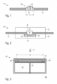
- FIG. 1 shows a schematic of a dewatering screen 10 with a screen fabric 12 into which a watermark insert is injected in the area of a recess 14.
- the watermark insert 20 has a high-resolution, multi-level injection-molded relief 22, which allows a very detailed representation of graphic motifs, for example a portrait.
- the watermark insert 20 is provided with a plurality of small perforations 24 in order to ensure dewatering in the area of the watermark insert 20 during paper production.
- FIG. 2 shows an injection molding tool 30 according to the invention for injecting the watermark insert 20 into the drainage screen 10 of the Fig.1 .
- the injection molding tool 30 contains a nozzle tool 32, which serves as an injection molding tool upper part, and a relief tool 50, which serves as an injection molding tool lower part.
- the nozzle tool 32 is designed in the form of a flat plate with an upper side and a lower side.
- a nozzle tool cavity 36 is formed in the nozzle tool 32 on its lower side, which is connected to a nozzle opening arranged on the top of the nozzle tool 32 for injecting plastic into the nozzle tool cavity 36.
- the relief tool 50 is also designed in the form of a flat plate with an upper side and a lower side, wherein a 3D-printed relief insert 40 is inserted into the relief tool 50 on the top side, which is provided on its top side with a high-resolution, multi-level watermark relief 54 in the form of the inverted injection molding relief 22.
- the injection molding tool 30 with nozzle tool 32 and relief tool 50 is moved to the recessed areas of the dewatering screen 10 so that the nozzle tool 32 is arranged above and the relief tool 50 with the relief insert 40 is arranged congruently below the recess 14.
- the two tools 32, 50 are then brought together in a vertical direction so that they hold the dewatering screen 10 between them in the area of the recess 14 with a predetermined pressure.
- the injection molding tool 30 forms an injection molding cavity 56 which comprises the nozzle tool cavity 36 and the recess 14 of the dewatering screen 10 and which is delimited on its underside by the watermark relief 54 of the relief insert 40 of the relief tool 50.
- a watermark insert 20 with the desired injection molding relief 22 is created which is injected directly into the dewatering screen 10.
- the dewatering screen 10 contains a watermark insert 20 with the high-resolution relief 22, as shown in Fig.1 shown.
- the relief insert 40 of the relief tool 50 comprises a base plate with the high-resolution multi-level watermark relief 54, wherein the relief insert 40 including base plate and relief 54 is formed by an additive manufacturing process as a layer sequence of a plurality of firmly connected material layers 42.
- this 3D-printed relief insert 40 is inserted into a relief tool 50 produced in a conventional manner.
- the present invention provides an effective and highly accurate manufacturing process for producing the essential part 40 of the injection molding tool containing the watermark relief 54.
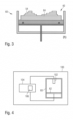
- the process is described below with reference to Figure 3 explained in detail, which shows in (a) to (h) various intermediate steps in an exemplary production of the relief insert 40.
- a 3D printing device 60 shown in detail contains a movable work plate 62 that can be moved vertically in a processing space 64.
- the relief insert 40 is built on a construction platform 66 that is detachably connected to the work plate 62 via several locating pins 68.
- the locating pins 68 and corresponding recesses in the construction platform 66 ensure that the construction platform can be removed from the 3D printing device and subsequently reinserted into the 3D printing device in the correct position.
- a relief insert blank 84 it is produced in the 3D printing device 60 by selective laser beam melting (LBM), i.e. by layer-by-layer application and selective solidification of a building material.
- LBM laser beam melting
- an associated high-resolution, multi-level watermark relief 54 is first determined on the basis of the specified injection molding relief 22 of the watermark set 20, which produces the desired injection molding relief when the plastic is later injected into the injection molding cavity 56.
- This determination is preferably carried out with the aid of a computer and includes an inversion of the specified injection molding relief 22.
- further processing steps can be provided which take into account the special features of the manufacturing process according to the invention. For example, it can be advantageous for the laser polishing step described below if the watermark relief 54 does not have completely vertical structures.
- any vertical structures in the injection molding relief 22 are replaced by slightly inclined structures in the watermark relief 54.
- inclination angles ⁇ between 0.5° and 4°, preferably between 1.5° and 3°, in particular of about 2.5° to the vertical have proven to be advantageous.
- all structures of the injection molding relief 22 with an inclination angle between 90° and 90°- ⁇ in the watermark relief 54 are replaced by slightly inclined structures with an inclination angle 90°- ⁇ .
- the 3D data of the watermark relief 54 determined in this way form a data set that is transmitted as a construction file to a computer unit, which controls the 3D printing device 60 accordingly on the basis of this data set.
- the graphic representation in Fig.3 is highly schematic to illustrate the principle of the invention.
- the granulate or powder particles of the building material usually have different sizes in practice, in the example example a maximum size of 63 ⁇ m. This is used, for example, to solidify powder layers of a Layer thickness of about 20 ⁇ m.
- the relief insert blank is constructed not only from a few, but from a large number of separately applied and solidified layers, so that a high resolution and detail fidelity of the watermark relief 54 can be achieved.
- a first granulate or powder layer 70 of the building material is applied to the building platform 66.
- the building material is fused together in the area 72 of the desired dimensions of the blank by laser impact 74 and thereby selectively solidified.
- the selectively solidified material layer 76 has a relatively large surface waviness 78. The size of the waviness of the material layer 76 depends on the details of the construction process and is, for example, just under 10 ⁇ m.
- the work plate 62 is lowered step by step and further layers of granules or powder are applied and solidified to complete the base plate 80 of the watermark insert 20, as shown in Fig. 3(c) As illustrated in the figure, the waviness of the first layer 76 was leveled by the subsequent layers applied over the entire surface, while the top layer 82 of the base plate 80 has a relatively large surface waviness 78 due to the manufacturing process.
- the work plate 62 is then lowered further and the relief is gradually built up on the base plate 80 in the desired form using the 3D data supplied by the computer unit until the complete relief insert blank 84 is finally built up, as shown in Fig. 3(d)
- the watermark relief 54 of the blank is in practice usually much more complex than the schematic representation of the Fig. 3(d)
- the watermark relief can also contain binary relief areas with large differences in height that replicate electrotypes. Due to their high contrast, such binary areas are particularly well suited to generating character sequences and in particular value numbers, such as the denomination of a banknote in the watermark.
- the surface of the relief insert blank 84 after its completion is typically covered with non-fused build-up material 86.
- the top layer of each step also has the already mentioned, relatively large surface waviness 78.
- Fig. 3(d) It is also clear that the step height does not have to coincide with the layer height, since steps can also be formed by a sequence of several layers. With the layer height of the solidified powder layers of 20 ⁇ m, the steps of the watermark relief 54 have a minimum step height of 20 ⁇ m, so that very fine brightness gradations are possible in the watermark.
- the blank 84 is removed from the 3D printing device 60 and the processing space 64 of the 3D printing device and the blank 84 are cleaned.
- the cleaned relief insert blank 84 is then reinserted into the cleaned 3D printing device 60, as shown in Fig. 3(e)
- the precise positioning of the relief insert blank 84 is possible with the dowel pins 68 with practically no position tolerances.
- the work plate 62 with the blank is then moved to a position in which the surface of the first layer to be smoothed lies in the processing plane 90, for example the focal plane of the processing laser ( Fig. 3(e) ).
- the first layer to be smoothed is the top layer 82 of the base plate 80 of the blank 84.
- the exposed surface areas 92 of the layer 82 are now to be smoothed, i.e. those surface areas 92 on which no further layer has been built up.
- the required information about the shape and position of these surface areas 92 is available in the data set stored in the computer unit.
- no material is removed in the process, but the wavy surface 78 is melted together with any adhering particles by the incident laser energy and these unevennesses are integrated into the surface of the layer 82.
- the surface tension of the layer is also reduced by completely melting the layer areas close to the edge.
- Figure 3(f) shows schematically the state of the blank 84 after remelting polishing of the first layer 82 with now smoothed surface areas 92.
- FIG. 3(g) shows schematically the state of the blank 84 after remelting polishing of the first and second layers with now smoothed surface areas 92, 96.
- the processing plane 90 used for remelting polishing does not necessarily have to be the focal plane of the laser radiation. In some designs, it may also be advisable to carry out the remelting polishing slightly outside the focal plane. The layers to be smoothed are then moved into this processing plane 90, which lies slightly outside the focal plane.
- the same laser system that is used for the selective solidification of the material layers when building the blank is advantageously used as the processing laser for remelting polishing, so that no additional laser source is required.
- Data transfer or adjustment of position data is also not required for remelting polishing, since the laser polishing step is carried out in the building device with precise position, so that the 3D data set already available there can be used to control the polishing step.
- FIG 4 shows schematically a device 100 for producing a watermark tool of the type described.
- the device 100 contains a 3D printing device 60 with a movable work plate 62 and a processing laser 102.
- the same processing laser 102 is used both for melting the build-up material during layer-by-layer construction and solidification of the blank, as well as for remelting polishing the surface irregularities of the built-up blank.
- the device 100 contains a computing unit 104.
- the construction file 106 is used in two ways, namely first for the layer-by-layer additive construction of the tool blank and subsequently for the step-by-step remelting polishing of the tool blank to smooth out the surface defects caused by the manufacturing process.
Claims (15)
- Procédé, destiné à fabriquer un outil de filigranage (30) pourvu d'une cavité de moulage par injection (56), qui est muni d'un relief en filigrane (54) multi-étagé et dans lequel, pour créer un ensemble de filigranes (20), de la matière plastique est injectable, lors du procédéV) un relief (22) moulé par injection multi-étagé, haute résolution souhaité étant prédéfini pour l'ensemble de filigranes (20),B) à partir du relief (22) moulé par injection, un relief en filigrane (54) multi-étagé, haute définition associé étant déterminé pour créer le relief (22) moulé par injection prédéfini,E) dans un dispositif d'impression (60) en 3 D, par application couche par couche et consolidation sélective d'une matière structurelle (70), une ébauche d'outil (84) avec le relief en filigrane (54) déterminé à l'étape B) étant créée,G) après l'étape E), l'ébauche d'outil (84) placée en position conforme dans le même dispositif d'impression (60) en 3 D étant polie par exposition au laser, pour lisser le relief en filigrane (54) créé etW) l'ébauche d'outil (40) polie étant usinée ultérieurement en un outil de filigranage (30), le relief en filigrane lissé à l'étape G) constituant le relief en filigrane multi-étagé, haute résolution de la cavité de moulage par injection (56) de l'outil de filigranage (30).
- Procédé selon la revendication 1, à l'étape G), l'ébauche d'outil (84) créée étant lissée étage par étage, conformément aux étages déterminés à l'étape B) du relief en filigrane (54).
- Procédé selon la revendication 2, dans chaque étage, chaque fois uniquement les zones superficielles du relief en filigrane (54) étant lissées, sur lesquelles à l'étape E) aucune couche supplémentaire n'a été construite.
- Procédé selon au moins l'une quelconque des revendications 1 à 3, l'ébauche d'outil (84) créée étant lissée à l'étape G) par polissage par refusion au laser.
- Procédé selon la revendication 4, l'ébauche d'outil (84) créée étant lissée à l'étape G) en deux étapes de polissage ou plus, qui sont réalisées avec différents paramètres du laser.
- Procédé selon la revendication 5, une étape de polissage étant réalisée par rayonnement laser à ondes entretenues et une étape de polissage étant réalisée par rayonnement laser pulsé.
- Procédé selon au moins l'une quelconque des revendications 1 à 6, l'ébauche d'outil (84) étant créée à l'étape E) sur un plan de travail (62) déplaçable et l'ébauche d'outil (84) créée étant déplacée à l'étape G) sur le plan de travail (62) pour le lissage des différents étages du relief en filigrane à différentes hauteurs.
- Procédé selon au moins l'une quelconque des revendications 1 à 7, entre les étapes E) et G), dans une étape E2), l'ébauche d'outil (84) étant enlevée du dispositif d'impression (60) en 3 D, le dispositif d'impression (60) en 3 D et de préférence également l'ébauche d'outil (84) étant nettoyés, et l'ébauche d'outil (84) étant alors réinsérée en position précise dans le dispositif d'impression (60) en 3 D.
- Procédé selon la revendication 8 dans l'étape E), l'ébauche d'outil (84) étant créée sur une plate-forme de construction (66) positionnée par l'intermédiaire de goupilles de serrage (68) sur le plan de travail (62) déplaçable et à l'étape E2), l'ébauche d'outil (84) étant enlevée avec la plate-forme de construction (66) du dispositif d'impression (60) en 3 D et après le nettoyage cité, la plate-forme de construction (66) avec l'ébauche d'outil (84) étant réinsérée par l'intermédiaire des goupilles de serrage (68) en position précise sur le plan de travail (62) déplaçable.
- Procédé selon au moins l'une quelconque des revendications 1 à 9, dans l'étape E), une matière de structure (70) notamment pulvérulente étant appliquée couche par couche et sélectivement consolidée par exposition au laser.
- Procédé selon la revendication 10, la solidification sélective à l'étape E) et le polissage par refusion au laser à l'étape G) étant réalisés avec le même système laser.
- Procédé selon au moins l'une quelconque des revendications 1 à 11, dans l'étape B), un jeu de données décrivant le relief en filigrane (54) multi-étagé, haute résolution étant créé et avec ledit jeu de données, aussi bien la construction couche par couche de l'ébauche d'outils (84) dans l'étape E), donc également le polissage, notamment le lissage par étages du relief en filigrane (54) étant commandée à l'étape G) .
- Procédé selon au moins l'une quelconque des revendications 1 à 12, à l'étape B) le relief (22) moulé par injection prédéfini étant inversé et de préférence par ailleurs, des structures verticales dans le relief (22) moulé par injection étant remplacées par des structures légèrement inclinées dans le relief en filigrane (54), les structures légèrement inclinées étant munies d'un angle d'inclinaison compris entre 0,5° et 4°, de préférence entre 1,5° et 3° contre la verticale.
- Dispositif, destiné à fabriquer un outil de filigranage (30) pourvu d'une cavité de moulage par injection (56), qui est munie d'un relief en filigrane (54) multi-étagé, haute résolution, doté- d'un plan de travail (62) déplaçable en hauteur et d'une plaque d'embase (80) assemblée de manière amovible mais en position conforme avec le plan de travail (62) déplaçable en hauteur, sur laquelle une ébauche d'outil (84) avec un relief en filigrane (54) multi-étagé, haute résolution est construite par application couche par couche et par consolidation sélective d'une matière structurelle (70),- d'un système d'irradiation, destiné à irradier sélectivement la matière structurelle (70),- d'un système de commande, qui est conçu pour-- commander d'une part le plan de travail (62) déplaçable en hauteur et le système d'irradiation pour la construction de l'ébauche d'outils (84) pourvue du relief en filigrane (54) multi-étagé, haute résolution et-- pour commander d'autre part le plan de travail (62) déplaçable en hauteur et le système d'irradiation pour le polissage pour l'ébauche d'outils (84) construite et pour le lissage du relief en filigrane (54) multi-étagé, haute résolution.
- Dispositif selon la revendication 14, le système d'irradiation étant un système laser.
Applications Claiming Priority (1)
| Application Number | Priority Date | Filing Date | Title |
|---|---|---|---|
| DE102019003496.1A DE102019003496A1 (de) | 2019-05-16 | 2019-05-16 | Verfahren und Vorrichtung zum Herstellen eines Wasserzeichen-Werkzeugs |
Publications (2)
| Publication Number | Publication Date |
|---|---|
| EP3739113A1 EP3739113A1 (fr) | 2020-11-18 |
| EP3739113B1 true EP3739113B1 (fr) | 2024-09-18 |
Family
ID=70682566
Family Applications (1)
| Application Number | Title | Priority Date | Filing Date |
|---|---|---|---|
| EP20020212.5A Active EP3739113B1 (fr) | 2019-05-16 | 2020-05-11 | Procédé et dispositif de fabrication d'un outil de filigranage |
Country Status (2)
| Country | Link |
|---|---|
| EP (1) | EP3739113B1 (fr) |
| DE (1) | DE102019003496A1 (fr) |
Families Citing this family (1)
| Publication number | Priority date | Publication date | Assignee | Title |
|---|---|---|---|---|
| DE102020007606A1 (de) | 2020-12-11 | 2022-06-15 | Giesecke+Devrient Currency Technology Gmbh | Entwässerungssieb, Spritzgusswerzeug und Verfahren zum Herstellungsverfahren für Entwässerungssiebe |
Family Cites Families (1)
| Publication number | Priority date | Publication date | Assignee | Title |
|---|---|---|---|---|
| DE102014008752A1 (de) | 2014-06-12 | 2015-12-17 | Giesecke & Devrient Gmbh | Spritzgusswerkzeug und Prägestock zum Einsatz bei der Herstellung von Wasserzeichenpapier |
-
2019
- 2019-05-16 DE DE102019003496.1A patent/DE102019003496A1/de not_active Withdrawn
-
2020
- 2020-05-11 EP EP20020212.5A patent/EP3739113B1/fr active Active
Also Published As
| Publication number | Publication date |
|---|---|
| DE102019003496A1 (de) | 2020-11-19 |
| EP3739113A1 (fr) | 2020-11-18 |
Similar Documents
| Publication | Publication Date | Title |
|---|---|---|
| EP3225334B1 (fr) | Procédé et dispositif de fabrication additive d'au moins une partie d'un composant | |
| EP3017343B1 (fr) | Procédé de fabrication d'un objet tridimensionnel | |
| DE10157647C5 (de) | Verfahren zur Herstellung von dreidimensionalen Werkstücken in einer Laser-Materialbearbeitungsanlage oder einer Stereolitographieanlage | |
| DE102017126624A1 (de) | Schichtselektive belichtung im überhangbereich bei der generativen fertigung | |
| DE112011100572T5 (de) | Verfahren zum herstellen eines dreidimensionalen formgegenstands und dreidimensionaler formgegenstand | |
| EP0738584A1 (fr) | Dispositif et procédé pour la fabrication d'un objet tridimensionnel | |
| EP1629994A2 (fr) | Feuille métallique en relief avec une structure tridimensionelle pour la fabrication de documents utilisant une presse de laminage chaude froide | |
| DE102013010160A1 (de) | Verfahren zur Herstellung einer Werkstoffplatte mittels eines Pressbleches oder Endlosbandes, sowie Pressblech oder Endlosband und Werkstoffplatte | |
| EP1667812B1 (fr) | Procede d'usinage d'une surface tridimensionnelle | |
| EP2346670A1 (fr) | Procédé et dispositif de production générative d'un objet tridimensionnel pourvu d'une marque codée en trois dimensions | |
| EP2643112B1 (fr) | Procédé de fabrication d'une pièce par couches | |
| DE102012018166A1 (de) | Spritzgusswerkzeug zur Erzeugung eines Wasserzeicheneinsatzes in einem Entwässerungssieb | |
| EP1663567A1 (fr) | Procede et dispositif d'enlevement de matiere multicouche d'une surface tridimensionnelle par laser a l'aide d'un reseau de polygones qui est decrit par une fonction mathematique et represente la surface | |
| WO2018086995A1 (fr) | Positionnement d'une plate-forme de construction dans un dispositif à lit en poudre pour la fabrication additive | |
| EP2954998B1 (fr) | Outil de moulage par injection emporte-pièce à dispositif estampeur utilisé lors de la fabrication de papier filigrane | |
| EP3739113B1 (fr) | Procédé et dispositif de fabrication d'un outil de filigranage | |
| DE112017005812T5 (de) | Verfahren zur herstellung eines 3d-gedruckten gegenstands | |
| DE102009004379B4 (de) | Verfahren zum Herstellen und Beschichten eines Brillenglases und Verwendung eines Werkstoffverarbeitungsgerätes | |
| EP1410924A1 (fr) | Procédé de production d'une forme d'impression pour la rotogravure, forme d'impression pour la rotogravure et utilisation de cette forme | |
| WO2019166166A1 (fr) | Retrait des structures de support de composants fabriqués par impression 3d | |
| DE102010024226A1 (de) | Verfahren und Vorrichtung zur Herstellung oder Reparatur von Bauteilen, insbesondere Bauteilen von Strömungsmaschinen, mittels eines generativen Herstellungsverfahrens | |
| EP2490893A1 (fr) | Procédé de fabrication de pochoirs perforés ou partiellement perforés présentant un relief | |
| DE10345087A1 (de) | Verfahren zur schichtabtragenden 3-dimensionalen Materialbearbeitung | |
| AT519582B1 (de) | Verfahren zum gravieren einer intaglio-stichtiefdruckplatte | |
| DE102022116423B4 (de) | Presswerkzeug und Verfahren zur Herstellung eines Presswerkzeugs |
Legal Events
| Date | Code | Title | Description |
|---|---|---|---|
| PUAI | Public reference made under article 153(3) epc to a published international application that has entered the european phase |
Free format text: ORIGINAL CODE: 0009012 |
|
| STAA | Information on the status of an ep patent application or granted ep patent |
Free format text: STATUS: THE APPLICATION HAS BEEN PUBLISHED |
|
| AK | Designated contracting states |
Kind code of ref document: A1 Designated state(s): AL AT BE BG CH CY CZ DE DK EE ES FI FR GB GR HR HU IE IS IT LI LT LU LV MC MK MT NL NO PL PT RO RS SE SI SK SM TR |
|
| AX | Request for extension of the european patent |
Extension state: BA ME |
|
| STAA | Information on the status of an ep patent application or granted ep patent |
Free format text: STATUS: REQUEST FOR EXAMINATION WAS MADE |
|
| 17P | Request for examination filed |
Effective date: 20210518 |
|
| RBV | Designated contracting states (corrected) |
Designated state(s): AL AT BE BG CH CY CZ DE DK EE ES FI FR GB GR HR HU IE IS IT LI LT LU LV MC MK MT NL NO PL PT RO RS SE SI SK SM TR |
|
| RAP3 | Party data changed (applicant data changed or rights of an application transferred) |
Owner name: GIESECKE+DEVRIENT CURRENCY TECHNOLOGY GMBH |
|
| P01 | Opt-out of the competence of the unified patent court (upc) registered |
Effective date: 20230519 |
|
| GRAP | Despatch of communication of intention to grant a patent |
Free format text: ORIGINAL CODE: EPIDOSNIGR1 |
|
| STAA | Information on the status of an ep patent application or granted ep patent |
Free format text: STATUS: GRANT OF PATENT IS INTENDED |
|
| INTG | Intention to grant announced |
Effective date: 20240326 |
|
| GRAJ | Information related to disapproval of communication of intention to grant by the applicant or resumption of examination proceedings by the epo deleted |
Free format text: ORIGINAL CODE: EPIDOSDIGR1 |
|
| STAA | Information on the status of an ep patent application or granted ep patent |
Free format text: STATUS: REQUEST FOR EXAMINATION WAS MADE |
|
| GRAP | Despatch of communication of intention to grant a patent |
Free format text: ORIGINAL CODE: EPIDOSNIGR1 |
|
| STAA | Information on the status of an ep patent application or granted ep patent |
Free format text: STATUS: GRANT OF PATENT IS INTENDED |
|
| GRAS | Grant fee paid |
Free format text: ORIGINAL CODE: EPIDOSNIGR3 |
|
| INTC | Intention to grant announced (deleted) | ||
| GRAA | (expected) grant |
Free format text: ORIGINAL CODE: 0009210 |
|
| STAA | Information on the status of an ep patent application or granted ep patent |
Free format text: STATUS: THE PATENT HAS BEEN GRANTED |
|
| INTG | Intention to grant announced |
Effective date: 20240807 |
|
| AK | Designated contracting states |
Kind code of ref document: B1 Designated state(s): AL AT BE BG CH CY CZ DE DK EE ES FI FR GB GR HR HU IE IS IT LI LT LU LV MC MK MT NL NO PL PT RO RS SE SI SK SM TR |
|
| REG | Reference to a national code |
Ref country code: GB Ref legal event code: FG4D Free format text: NOT ENGLISH |
|
| REG | Reference to a national code |
Ref country code: CH Ref legal event code: EP |
|
| REG | Reference to a national code |
Ref country code: DE Ref legal event code: R096 Ref document number: 502020009238 Country of ref document: DE |
|
| REG | Reference to a national code |
Ref country code: IE Ref legal event code: FG4D Free format text: LANGUAGE OF EP DOCUMENT: GERMAN |
|
| REG | Reference to a national code |
Ref country code: NL Ref legal event code: FP |
|
| REG | Reference to a national code |
Ref country code: SE Ref legal event code: TRGR |
|
| REG | Reference to a national code |
Ref country code: LT Ref legal event code: MG9D |
|
| PG25 | Lapsed in a contracting state [announced via postgrant information from national office to epo] |
Ref country code: NO Free format text: LAPSE BECAUSE OF FAILURE TO SUBMIT A TRANSLATION OF THE DESCRIPTION OR TO PAY THE FEE WITHIN THE PRESCRIBED TIME-LIMIT Effective date: 20241218 |
|
| PG25 | Lapsed in a contracting state [announced via postgrant information from national office to epo] |
Ref country code: GR Free format text: LAPSE BECAUSE OF FAILURE TO SUBMIT A TRANSLATION OF THE DESCRIPTION OR TO PAY THE FEE WITHIN THE PRESCRIBED TIME-LIMIT Effective date: 20241219 Ref country code: FI Free format text: LAPSE BECAUSE OF FAILURE TO SUBMIT A TRANSLATION OF THE DESCRIPTION OR TO PAY THE FEE WITHIN THE PRESCRIBED TIME-LIMIT Effective date: 20240918 |
|
| PG25 | Lapsed in a contracting state [announced via postgrant information from national office to epo] |
Ref country code: BG Free format text: LAPSE BECAUSE OF FAILURE TO SUBMIT A TRANSLATION OF THE DESCRIPTION OR TO PAY THE FEE WITHIN THE PRESCRIBED TIME-LIMIT Effective date: 20240918 |
|
| PG25 | Lapsed in a contracting state [announced via postgrant information from national office to epo] |
Ref country code: LV Free format text: LAPSE BECAUSE OF FAILURE TO SUBMIT A TRANSLATION OF THE DESCRIPTION OR TO PAY THE FEE WITHIN THE PRESCRIBED TIME-LIMIT Effective date: 20240918 |
|
| PG25 | Lapsed in a contracting state [announced via postgrant information from national office to epo] |
Ref country code: HR Free format text: LAPSE BECAUSE OF FAILURE TO SUBMIT A TRANSLATION OF THE DESCRIPTION OR TO PAY THE FEE WITHIN THE PRESCRIBED TIME-LIMIT Effective date: 20240918 |
|
| PG25 | Lapsed in a contracting state [announced via postgrant information from national office to epo] |
Ref country code: RS Free format text: LAPSE BECAUSE OF FAILURE TO SUBMIT A TRANSLATION OF THE DESCRIPTION OR TO PAY THE FEE WITHIN THE PRESCRIBED TIME-LIMIT Effective date: 20241218 |
|
| PG25 | Lapsed in a contracting state [announced via postgrant information from national office to epo] |
Ref country code: RS Free format text: LAPSE BECAUSE OF FAILURE TO SUBMIT A TRANSLATION OF THE DESCRIPTION OR TO PAY THE FEE WITHIN THE PRESCRIBED TIME-LIMIT Effective date: 20241218 Ref country code: NO Free format text: LAPSE BECAUSE OF FAILURE TO SUBMIT A TRANSLATION OF THE DESCRIPTION OR TO PAY THE FEE WITHIN THE PRESCRIBED TIME-LIMIT Effective date: 20241218 Ref country code: LV Free format text: LAPSE BECAUSE OF FAILURE TO SUBMIT A TRANSLATION OF THE DESCRIPTION OR TO PAY THE FEE WITHIN THE PRESCRIBED TIME-LIMIT Effective date: 20240918 Ref country code: HR Free format text: LAPSE BECAUSE OF FAILURE TO SUBMIT A TRANSLATION OF THE DESCRIPTION OR TO PAY THE FEE WITHIN THE PRESCRIBED TIME-LIMIT Effective date: 20240918 Ref country code: GR Free format text: LAPSE BECAUSE OF FAILURE TO SUBMIT A TRANSLATION OF THE DESCRIPTION OR TO PAY THE FEE WITHIN THE PRESCRIBED TIME-LIMIT Effective date: 20241219 Ref country code: FI Free format text: LAPSE BECAUSE OF FAILURE TO SUBMIT A TRANSLATION OF THE DESCRIPTION OR TO PAY THE FEE WITHIN THE PRESCRIBED TIME-LIMIT Effective date: 20240918 Ref country code: BG Free format text: LAPSE BECAUSE OF FAILURE TO SUBMIT A TRANSLATION OF THE DESCRIPTION OR TO PAY THE FEE WITHIN THE PRESCRIBED TIME-LIMIT Effective date: 20240918 |
|
| PG25 | Lapsed in a contracting state [announced via postgrant information from national office to epo] |
Ref country code: IS Free format text: LAPSE BECAUSE OF FAILURE TO SUBMIT A TRANSLATION OF THE DESCRIPTION OR TO PAY THE FEE WITHIN THE PRESCRIBED TIME-LIMIT Effective date: 20250118 Ref country code: PT Free format text: LAPSE BECAUSE OF FAILURE TO SUBMIT A TRANSLATION OF THE DESCRIPTION OR TO PAY THE FEE WITHIN THE PRESCRIBED TIME-LIMIT Effective date: 20250120 |
|
| PG25 | Lapsed in a contracting state [announced via postgrant information from national office to epo] |
Ref country code: RO Free format text: LAPSE BECAUSE OF FAILURE TO SUBMIT A TRANSLATION OF THE DESCRIPTION OR TO PAY THE FEE WITHIN THE PRESCRIBED TIME-LIMIT Effective date: 20240918 Ref country code: SM Free format text: LAPSE BECAUSE OF FAILURE TO SUBMIT A TRANSLATION OF THE DESCRIPTION OR TO PAY THE FEE WITHIN THE PRESCRIBED TIME-LIMIT Effective date: 20240918 |
|
| PG25 | Lapsed in a contracting state [announced via postgrant information from national office to epo] |
Ref country code: ES Free format text: LAPSE BECAUSE OF FAILURE TO SUBMIT A TRANSLATION OF THE DESCRIPTION OR TO PAY THE FEE WITHIN THE PRESCRIBED TIME-LIMIT Effective date: 20240918 |
|
| PG25 | Lapsed in a contracting state [announced via postgrant information from national office to epo] |
Ref country code: EE Free format text: LAPSE BECAUSE OF FAILURE TO SUBMIT A TRANSLATION OF THE DESCRIPTION OR TO PAY THE FEE WITHIN THE PRESCRIBED TIME-LIMIT Effective date: 20240918 |
|
| PG25 | Lapsed in a contracting state [announced via postgrant information from national office to epo] |
Ref country code: CZ Free format text: LAPSE BECAUSE OF FAILURE TO SUBMIT A TRANSLATION OF THE DESCRIPTION OR TO PAY THE FEE WITHIN THE PRESCRIBED TIME-LIMIT Effective date: 20240918 Ref country code: PL Free format text: LAPSE BECAUSE OF FAILURE TO SUBMIT A TRANSLATION OF THE DESCRIPTION OR TO PAY THE FEE WITHIN THE PRESCRIBED TIME-LIMIT Effective date: 20240918 |
|
| PG25 | Lapsed in a contracting state [announced via postgrant information from national office to epo] |
Ref country code: SK Free format text: LAPSE BECAUSE OF FAILURE TO SUBMIT A TRANSLATION OF THE DESCRIPTION OR TO PAY THE FEE WITHIN THE PRESCRIBED TIME-LIMIT Effective date: 20240918 Ref country code: IT Free format text: LAPSE BECAUSE OF FAILURE TO SUBMIT A TRANSLATION OF THE DESCRIPTION OR TO PAY THE FEE WITHIN THE PRESCRIBED TIME-LIMIT Effective date: 20240918 |
|
| PGFP | Annual fee paid to national office [announced via postgrant information from national office to epo] |
Ref country code: NL Payment date: 20250522 Year of fee payment: 6 |
|
| REG | Reference to a national code |
Ref country code: DE Ref legal event code: R097 Ref document number: 502020009238 Country of ref document: DE |
|
| PG25 | Lapsed in a contracting state [announced via postgrant information from national office to epo] |
Ref country code: DK Free format text: LAPSE BECAUSE OF FAILURE TO SUBMIT A TRANSLATION OF THE DESCRIPTION OR TO PAY THE FEE WITHIN THE PRESCRIBED TIME-LIMIT Effective date: 20240918 |
|
| PGFP | Annual fee paid to national office [announced via postgrant information from national office to epo] |
Ref country code: FR Payment date: 20250521 Year of fee payment: 6 |
|
| PLBE | No opposition filed within time limit |
Free format text: ORIGINAL CODE: 0009261 |
|
| STAA | Information on the status of an ep patent application or granted ep patent |
Free format text: STATUS: NO OPPOSITION FILED WITHIN TIME LIMIT |
|
| PGFP | Annual fee paid to national office [announced via postgrant information from national office to epo] |
Ref country code: SE Payment date: 20250522 Year of fee payment: 6 |
|
| 26N | No opposition filed |
Effective date: 20250619 |
|
| REG | Reference to a national code |
Ref country code: DE Ref legal event code: R119 Ref document number: 502020009238 Country of ref document: DE |
|
| REG | Reference to a national code |
Ref country code: CH Ref legal event code: H13 Free format text: ST27 STATUS EVENT CODE: U-0-0-H10-H13 (AS PROVIDED BY THE NATIONAL OFFICE) Effective date: 20251223 |
|
| PG25 | Lapsed in a contracting state [announced via postgrant information from national office to epo] |
Ref country code: LU Free format text: LAPSE BECAUSE OF NON-PAYMENT OF DUE FEES Effective date: 20250511 |
|
| PG25 | Lapsed in a contracting state [announced via postgrant information from national office to epo] |
Ref country code: CH Free format text: LAPSE BECAUSE OF NON-PAYMENT OF DUE FEES Effective date: 20250531 |
|
| GBPC | Gb: european patent ceased through non-payment of renewal fee |
Effective date: 20250511 |
|
| REG | Reference to a national code |
Ref country code: BE Ref legal event code: MM Effective date: 20250531 |
|
| PG25 | Lapsed in a contracting state [announced via postgrant information from national office to epo] |
Ref country code: MC Free format text: LAPSE BECAUSE OF FAILURE TO SUBMIT A TRANSLATION OF THE DESCRIPTION OR TO PAY THE FEE WITHIN THE PRESCRIBED TIME-LIMIT Effective date: 20240918 |
|
| PG25 | Lapsed in a contracting state [announced via postgrant information from national office to epo] |
Ref country code: GB Free format text: LAPSE BECAUSE OF NON-PAYMENT OF DUE FEES Effective date: 20250511 |
|
| PG25 | Lapsed in a contracting state [announced via postgrant information from national office to epo] |
Ref country code: IE Free format text: LAPSE BECAUSE OF NON-PAYMENT OF DUE FEES Effective date: 20250511 Ref country code: DE Free format text: LAPSE BECAUSE OF NON-PAYMENT OF DUE FEES Effective date: 20251202 |
|
| PG25 | Lapsed in a contracting state [announced via postgrant information from national office to epo] |
Ref country code: BE Free format text: LAPSE BECAUSE OF NON-PAYMENT OF DUE FEES Effective date: 20250531 |