EP3354835B1 - Verbundprofil - Google Patents
Verbundprofil Download PDFInfo
- Publication number
- EP3354835B1 EP3354835B1 EP17207775.2A EP17207775A EP3354835B1 EP 3354835 B1 EP3354835 B1 EP 3354835B1 EP 17207775 A EP17207775 A EP 17207775A EP 3354835 B1 EP3354835 B1 EP 3354835B1
- Authority
- EP
- European Patent Office
- Prior art keywords
- profile
- aluminium
- composite
- aluminum
- insulating
- Prior art date
- Legal status (The legal status is an assumption and is not a legal conclusion. Google has not performed a legal analysis and makes no representation as to the accuracy of the status listed.)
- Active
Links
Images
Classifications
-
- E—FIXED CONSTRUCTIONS
- E06—DOORS, WINDOWS, SHUTTERS, OR ROLLER BLINDS IN GENERAL; LADDERS
- E06B—FIXED OR MOVABLE CLOSURES FOR OPENINGS IN BUILDINGS, VEHICLES, FENCES OR LIKE ENCLOSURES IN GENERAL, e.g. DOORS, WINDOWS, BLINDS, GATES
- E06B3/00—Window sashes, door leaves, or like elements for closing wall or like openings; Layout of fixed or moving closures, e.g. windows in wall or like openings; Features of rigidly-mounted outer frames relating to the mounting of wing frames
- E06B3/04—Wing frames not characterised by the manner of movement
- E06B3/263—Frames with special provision for insulation
- E06B3/273—Frames with special provision for insulation with prefabricated insulating elements held in position by deformation of portions of the metal frame members
-
- E—FIXED CONSTRUCTIONS
- E06—DOORS, WINDOWS, SHUTTERS, OR ROLLER BLINDS IN GENERAL; LADDERS
- E06B—FIXED OR MOVABLE CLOSURES FOR OPENINGS IN BUILDINGS, VEHICLES, FENCES OR LIKE ENCLOSURES IN GENERAL, e.g. DOORS, WINDOWS, BLINDS, GATES
- E06B3/00—Window sashes, door leaves, or like elements for closing wall or like openings; Layout of fixed or moving closures, e.g. windows in wall or like openings; Features of rigidly-mounted outer frames relating to the mounting of wing frames
- E06B3/04—Wing frames not characterised by the manner of movement
- E06B3/263—Frames with special provision for insulation
- E06B3/26301—Frames with special provision for insulation with prefabricated insulating strips between two metal section members
- E06B3/26303—Frames with special provision for insulation with prefabricated insulating strips between two metal section members with thin strips, e.g. defining a hollow space between the metal section members
-
- E—FIXED CONSTRUCTIONS
- E06—DOORS, WINDOWS, SHUTTERS, OR ROLLER BLINDS IN GENERAL; LADDERS
- E06B—FIXED OR MOVABLE CLOSURES FOR OPENINGS IN BUILDINGS, VEHICLES, FENCES OR LIKE ENCLOSURES IN GENERAL, e.g. DOORS, WINDOWS, BLINDS, GATES
- E06B3/00—Window sashes, door leaves, or like elements for closing wall or like openings; Layout of fixed or moving closures, e.g. windows in wall or like openings; Features of rigidly-mounted outer frames relating to the mounting of wing frames
- E06B3/04—Wing frames not characterised by the manner of movement
- E06B3/26—Compound frames, i.e. one frame within or behind another
- E06B3/2605—Compound frames, i.e. one frame within or behind another with frames permanently mounted behind or within each other, each provided with a pane or screen
- E06B2003/2615—Frames made of metal
-
- E—FIXED CONSTRUCTIONS
- E06—DOORS, WINDOWS, SHUTTERS, OR ROLLER BLINDS IN GENERAL; LADDERS
- E06B—FIXED OR MOVABLE CLOSURES FOR OPENINGS IN BUILDINGS, VEHICLES, FENCES OR LIKE ENCLOSURES IN GENERAL, e.g. DOORS, WINDOWS, BLINDS, GATES
- E06B3/00—Window sashes, door leaves, or like elements for closing wall or like openings; Layout of fixed or moving closures, e.g. windows in wall or like openings; Features of rigidly-mounted outer frames relating to the mounting of wing frames
- E06B3/04—Wing frames not characterised by the manner of movement
- E06B3/263—Frames with special provision for insulation
- E06B2003/26349—Details of insulating strips
- E06B2003/2635—Specific form characteristics
- E06B2003/26352—Specific form characteristics hollow
Definitions
- the present invention relates to a composite profile, in particular for facades, doors or windows, according to the preamble of claim 1.
- the DE 34 07 121 A1 discloses a composite profile in which a metallic inner part and a metallic outer part are connected to each other via a plurality of insulating webs of plastic.
- each insulating web has at its inner and outer parts facing edge regions roughness in the form of depressions or elevations.
- the metallic webs are reshaped in order to then form-fit around the edge regions of the insulating webs.
- the metallic outer and inner part usually consists of a deformable metal, such as aluminum or an aluminum alloy. In such composite profiles, the load capacity is limited, since metallic profiles are used, which can be deformed to make the connection.
- the EP 0 262 677 A2 shows a composite profile with three metal profiles, between each of which insulating rails made of plastic are provided.
- the DE 10 2015 007 611 A1 discloses an insulating element for a thermally insulated composite profile which is connected to a metallic profile part by rolling. For this purpose, a curl head is provided which is glued to the insulating body. As a result, completely different materials, such as the insulating body made of plastic and a profile part, can be connected to each other by rolling. However, the mechanical load capacity is determined by the profile part, which is formed during rolling.
- EP 1 199 434 A1 is a composite profile shown with two spaced by insulating webs of plastic profiles made of aluminum, wherein a wood element is fixed to a profile made of aluminum.
- This composite profile discloses all features of the preamble of claim 1.
- first an insulating profile made of plastic is arranged between a first profile made of aluminum and a second profile made of aluminum, so that the thermal conductivity between the first profile and the second profile is low.
- a third profile is provided, wherein the three profiles and the insulating profile are connected by deformation of the first and second profile made of aluminum form-fitting manner to a composite profile and the third profile is formed with higher strength than the second profile made of aluminum.
- the higher strength of the material of the third profile comprises at least the compressive strength and the bending strength, preferably also the tensile strength and the buckling and shear strength is higher.
- the third profile is made of an aluminum alloy.
- aluminum alloys with a higher strength are used for the third profile than in the case of the second profile made of aluminum, which still has to be deformed for connection.
- the material of the third profile also has a higher hardness than the material of the second profile.
- the third profile of an aluminum alloy is preferably also formed with higher compressive strength and bending strength than the first profile. Also, the first profile is deformed with the insulating profile by forming and therefore requires a corresponding deformability, so that the third profile of the profiles of aluminum preferably has the greatest strength.
- the profiles are preferably extruded.
- the profiles may be extruded as hollow profiles, L-shaped profiles or with different geometries.
- the cross-sectional area of the third aluminum alloy profile is greater than the cross-sectional area of the first aluminum profile. Since the third profile is particularly important for the mechanical load-bearing capacity of the composite profile, a large cross-sectional area of the third profile can result in a high profile Load transfer can be obtained.
- the cross-sectional area of the third profile is preferably three times as large, in particular five times as large as the cross-sectional area the first aluminum profile. This results in a particularly high bending stiffness of the composite profile.
- the first and / or second profile can be deformed by rolling. It is also possible to use other forming techniques, however, curling or rolling is particularly well suited for a continuous deformation process.
- the first and second profiles can be made of the same aluminum alloy.
- the third aluminum profile preferably has an E-modulus of at least 69 GPa.
- the third profile is preferably arranged on an inner side, for example in a mullion-and-transom construction of a façade or a light roof, or in the case of a window or a door.
- a composite profile 9 comprises a first profile 1 of aluminum and a second profile 2 of aluminum, which consist of a deformable aluminum alloy. Between the first profile 1 and the second profile 2, at least one insulating profile 3 made of plastic is provided, wherein the insulating profile 3 can be arranged flush with the profiles 1 and 2.
- the second profile 2 made of aluminum is connected on the side facing away from the insulating profile 3 side with a third profile 4 made of an aluminum alloy.
- aluminum when used in the present application, it is intended to include both aluminum as a pure substance and aluminum alloys.
- Aluminum alloys contain other additives in addition to aluminum, such as copper, magnesium, lead, manganese, silicon or other ingredients.
- the third profile 4 made of an aluminum alloy has a greater hardness and a greater strength than the second profile 2 made of aluminum, preferably also as the first profile 1 made of aluminum.
- the third profile 4 made of an aluminum alloy may consist, for example, of an aluminum alloy in accordance with DIN EN-573-3 W IN AW-6063, EN AW 7003, EN AW-6005 A, EN AW-60A2, EN AW-6106.
- the first profile 1 and the second profile 2 are formed.
- the first profile 1 has a U-shaped receptacle, with a first leg 10 and a second leg 11, between which a T-shaped central web 12 is provided.
- the insulating profile 3 engages the insulating profile 3 with a first arcuate or hook-shaped portion 30 which is disposed between the leg 10 and the central web 12, and engages with a second arcuate or hook-shaped portion 31 between the legs 11 and the central web 12 a.
- the second profile 2 made of aluminum is provided, which has only a small cross-sectional area and serves as a connecting piece between the insulating profile 3 and the third profile 4 of an aluminum alloy.
- the second profile 2 of aluminum wiest on opposite sides U-shaped receptacles, and has on the side facing the insulating profile 3 a first web 20, a second web 21 and a T-shaped central web 22. From the insulating 3 engages a first arcuate or hook-shaped portion 32 between the web 20 and the central web 22, and a second arcuate or hook-shaped portion 33 engages between the web 21 and the central web 22 a.
- the second profile 2 On the side facing the third profile 4 of an aluminum alloy, the second profile 2 likewise has a U-shaped receptacle with two webs 23 and 24, each having an inwardly angled web. The inside Angled web engages in a groove on the connecting portion 40 of the third profile 4 a.
- the second aluminum profile 2 can be deformed by rollers 5 and 7 which are rotatable about axes 6 and 8.
- rollers 5 and 7 By the rollers 5 and 7, the webs 20, 21, 23 and 24 deformed inwardly to produce a positive and possibly also non-positive connection with the insulating profile 3 and the third profile 4 made of aluminum.
- the composite profile 9 is shown after rolling.
- the first profile 1 and the second profile 2 were rolled out of aluminum, while the insulating profile 3 and the third profile 4 were not deformed from an aluminum alloy.
- a harder, less elastic aluminum alloy is used for the third profile 4 made of an aluminum alloy, which can absorb higher mechanical loads.
- the cross-sectional area of the third profile 4 made of an aluminum alloy is chosen larger than that of the first profile 1 and the second profile 2 made of aluminum, in particular at least twice as large, preferably more than three times as large.
- the composite profile 9 consists of four individual profiles.
- two insulating profiles 3 can be arranged in parallel between the first profile 1 and the second profile 2.
- the composite profile 9 according to the invention can be used in particular for facades, doors or windows, wherein preferably the higher loadable third profile 4 forms an inner shell, that is arranged on the inside.
Landscapes
- Engineering & Computer Science (AREA)
- Civil Engineering (AREA)
- Structural Engineering (AREA)
- Wing Frames And Configurations (AREA)
Description
- Die vorliegende Erfindung betrifft ein Verbundprofil, insbesondere für Fassaden, Türen oder Fenster, nach dem Oberbegriff des Anspruches 1.
- Die
DE 34 07 121 A1 offenbart ein Verbundprofil, bei dem ein metallisches Innenteil und ein metallisches Außenteil über mehrere Isolierstege aus Kunststoff miteinander verbunden sind. Um eine schubfeste Verbindung zwischen den Isolierstegen und den metallischen Innen- und Außenteilen herzustellen, weist jeder Isoliersteg an seinen den Innen- und Außenteilen zugekehrten Randbereichen Rauigkeiten in Gestalt von Vertiefungen oder Erhöhungen auf. Um eine Verbindung herzustellen, werden die metallischen Stege umgeformt, um dann die Randbereiche der Isolierstege formschlüssig zu umgreifen. Das metallische Außen- und Innenteil besteht meist aus einem verformbaren Metall, wie Aluminium oder einer Aluminiumlegierung. Bei solchen Verbundprofilen ist die Belastbarkeit begrenzt, da metallische Profile eingesetzt werden, die zur Herstellung der Verbindung verformt werden können. - Die
EP 0 262 677 A2 zeigt ein Verbundprofil mit drei Metallprofilen, zwischen denen jeweils Isolierschienen aus Kunststoff vorgesehen sind. - Die
DE 10 2015 007 611 A1 offenbart ein Isolierelement für ein wärmegedämmtes Verbundprofil, das mit einem metallischen Profilteil durch Einrollen verbunden ist. Hierfür ist ein Einrollkopf vorgesehen, der mit dem Isolierkörper verklebt ist. Dadurch können völlig unterschiedliche Materialien, wie der Isolierkörper aus Kunststoff und ein Profilteil, durch Einrollen miteinander verbunden werden. Allerdings wird die mechanische Belastbarkeit durch das Profilteil vorgegeben, das beim Einrollen umgeformt wird. - In der
EP 1 199 434 A1 ist ein Verbundprofil mit zwei durch Isolierstege aus Kunststoff beabstandete Profile aus Aluminium gezeigt, wobei an einem Profil aus Aluminium ein Holzelement fixiert ist. Dieses Verbundprofil offenbart alle Merkmale des Oberbegriffs des Anspruchs 1. - Es ist daher Aufgabe der vorliegenden Erfindung, ein Verbundprofil zu schaffen, das eine gute Wärmeisolierung und eine hohe mechanische Belastbarkeit aufweist.
- Diese Aufgabe wird mit einem Verbundprofil mit den Merkmalen des Anspruches 1 gelöst.
- Bei dem erfindungsgemäßen Verbundprofil ist zunächst en Isolierprofil aus Kunststoff zwischen einem ersten Profil aus Aluminium und einem zweiten Profil aus Aluminium angeordnet, so dass die Wärmeleitfähigkeit zwischen dem ersten Profil und dem zweiten Profil gering ist. Zusätzlich ist ein drittes Profil vorgesehen, wobei die drei Profile und das Isolierprofil durch Verformung des ersten und des zweiten Profils aus Aluminium formschlüssig zu einem Verbundprofil miteinander verbunden sind und das dritte Profil mit höherer Festigkeit ausgebildet ist als das zweite Profil aus Aluminium. Dadurch können mechanische Lasten insbesondere durch das dritte Profil aufgenommen werden, das zur Verbindung mit dem zweiten Profil aus Aluminium nicht verformt werden muss, sondern formschlüssig mit dem zweiten Profil verbunden wird, indem nur das zweite Profil aus Aluminium verformt wird. Die höhere Festigkeit des Materials des dritten Profils umfasst zumindest die Druckfestigkeit und die Biegefestigkeit, vorzugsweise ist auch die Zugfestigkeit sowie die Knick- und Scherfestigkeit höher.
- Erfindungsgemäß ist das dritte Profil aus einer Aluminiumlegierung hergestellt. Erfindungsgemäß werden für das dritte Profil Aluminiumlegierungen mit höherer Festigkeit eingesetzt, als bei dem zweiten Profil aus Aluminium, das zur Verbindung noch verformt werden muß. Vorzugsweise weist das Material des dritten Profils auch eine höhere Härte als das Material des zweiten Profils auf.
- Das dritte Profil aus einer Aluminiumlegierung ist vorzugsweise auch mit höherer Druckfestigkeit und Biegefestigkeit ausgebildet als das erste Profil. Auch das erste Profil wird mit dem Isolierprofil durch Umformen verformt und benötigt daher eine entsprechende Verformbarkeit, so dass das dritte Profil von den Profilen aus Aluminium vorzugsweise die größte Festigkeit besitzt.
- Die Profile sind vorzugsweise extrudiert. Dabei können die Profile als Hohlprofile, L-förmige Profile oder mit unterschiedlichen Geometrien extrudiert sein.
- Vorzugsweise ist die Querschnittsfläche des dritten Profils aus einer Aluminiumlegierung größer als die Querschnittsfläche des ersten Profils aus Aluminium. Da das dritte Profil für die mechanische Belastbarkeit des Verbundprofils besonders wichtig ist, kann durch eine große Querschnittsfläche des dritten Profils eine hohe Lastabtragung erhalten werden. Die Querschnittsfläche des dritten Profils ist vorzugsweise dreimal so groß, insbesondere fünfmal so groß, wie die Querschnittsfläche des ersten Profils aus Aluminium. Dadurch ergibt sich eine besonders hohe Biegesteifigkeit des Verbundprofils.
- Um die Profile formschlüssig miteinander zu verbunden, können das erste und/oder zweite Profil durch Verrollen verformt werden. Es ist auch möglich, andere Umformtechniken einzusetzen, allerdings eignet sich das Einrollen oder Verrollen besonders gut für ein kontinuierliches Verformungsverfahren.
- Für eine effektive Herstellung können das erste und das zweite Profil aus einer gleichen Aluminiumlegierung herstellt werden.
- Das dritte Profil aus Aluminium weist vorzugsweise ein E-Modul von mindestens 69 GPa auf.
- Im montierten Zustand ist das dritte Profil vorzugsweise auf einer Innenseite angeordnet, beispielsweise bei einer Pfosten-Riegel-Konstruktion einer Fassade oder eines Lichtdaches, oder bei einem Fenster oder einer Tür.
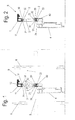
- Die Erfindung wird nachfolgend anhand eines Ausführungsbeispiels mit Bezug auf die beigefügten Zeichnungen näher erläutert. Es zeigen:
- Figur 1
- eine Ansicht bei der Herstellung eines erfindungsgemäßen Verbundprofils, und
- Figur 2
- eine Ansicht des Verbundprofils im fertigen Zustand.
- Ein Verbundprofil 9 umfasst ein erstes Profil 1 aus Aluminium und ein zweites Profil 2 aus Aluminium, die aus einer verformbaren Aluminiumlegierung bestehen. Zwischen dem ersten Profil 1 und dem zweiten Profil 2 ist mindestens ein Isolierprofil 3 aus Kunststoff vorgesehen, wobei das Isolierprofil 3 mit den Profilen 1 und 2 flächenbündig angeordnet sein kann. Das zweite Profil 2 aus Aluminium ist auf der vom Isolierprofil 3 abgewandten Seite mit einem dritten Profil 4 aus einer Aluminiumlegierung verbunden.
- Wenn in der vorliegenden Anmeldung der Begriff "Aluminium" verwendet wird, sollen sowohl Aluminium als Reinstoff als auch Aluminiumlegierungen umfasst sein. Aluminiumlegierungen enthalten weitere Zusatzstoffe neben Aluminium, beispielsweise Kupfer, Magnesium, Blei, Mangan, Silizium oder andere Inhaltsstoffe.
- Das dritte Profil 4 aus einer Aluminiumlegierung besitzt eine größere Härte und eine größere Festigkeit als das zweite Profil 2 aus Aluminium, vorzugsweise auch als das erste Profil 1 aus Aluminium. Das dritte Profil 4 aus einer Aluminiumlegierung kann beispielsweise aus einer Aluminiumlegierung gemäß DIN EN-573-3 W IN AW-6063, EN AW 7003, EN AW-6005 A, EN AW-60A2, EN AW-6106 bestehen.
- Um eine formschlüssige und gegebenenfalls auch kraftschlüssige Verbindung zwischen den einzelnen Profilen herzustellen, werden das erste Profil 1 und das zweite Profil 2 umgeformt. Das erste Profil 1 weist eine U-förmige Aufnahme auf, mit einem ersten Schenkel 10 und einem zweiten Schenkel 11, zwischen denen ein T-förmiger Mittelsteg 12 vorgesehen ist. In diese Aufnahme an dem ersten Profil 1 greift der Isolierprofil 3 mit einem ersten bogenförmigen oder hakenförmigen Abschnitt 30 ein, der zwischen dem Schenkel 10 und dem Mittelsteg 12 angeordnet ist, und greift mit einem zweiten bogen- oder hakenförmigen Abschnitt 31 zwischen dem Schenkel 11 und dem Mittelsteg 12 ein. Durch Eindrücken der Schenkel 10 und 11 zu dem Mittelsteg 12 hin können die beiden Abschnitte 30 und 31 des I Isolierprofils 3 formschlüssig fixiert werden und sind durch den Mittelsteg 12 gegen ein Herausziehen gesichert.
- Auf der gegenüberliegenden Seite des Isolierprofils 3 ist das zweite Profil 2 aus Aluminium vorgesehen, das nur eine geringe Querschnittsfläche aufweist und als Verbindungsstück zwischen dem Isolierprofil 3 und dem dritten Profil 4 aus einer Aluminiumlegierung dient. Das zweite Profil 2 aus Aluminium wiest auf gegenüberliegenden Seiten U-förmige Aufnahmen auf, und besitzt auf der zu dem Isolierprofil 3 gewandten Seite einen ersten Steg 20, einen zweiten Steg 21 und einen T-förmigen Mittelsteg 22. Von dem Isolierprofil 3 greift ein erster bogen- oder hakenförmiger Abschnitt 32 zwischen dem Steg 20 und dem Mittelsteg 22 ein, und ein zweiter bogen- oder hakenförmiger Abschnitt 33 greift zwischen dem Steg 21 und dem Mittelsteg 22 ein.
- Auf der zu dem dritten Profil 4 aus einer Aluminiumlegierung gewandten Seite weist das zweite Profil 2 ebenfalls eine U-förmige Aufnahme mit zwei Stegen 23 und 24 auf, die jeweils einen nach innen abgewinkelten Steg aufweisen. Der nach innen abgewinkelte Steg greift in eine Nut an dem Verbindungsabschnitt 40 des dritten Profils 4 ein.
- Wie in
Figur 1 gezeigt ist, kann das zweite Profil 2 aus Aluminium durch Rollen 5 und 7 verformt werden, die um Achsen 6 und 8 drehbar sind. Durch die Rollen 5 und 7 werden die Stege 20, 21, 23 und 24 nach innen verformt, um eine formschlüssige und gegebenenfalls auch kraftschlüssige Verbindung mit dem Isolierprofil 3 und dem dritten Profil 4 aus Aluminium herzustellen. - In
Figur 2 ist das Verbundprofil 9 nach dem Verrollen gezeigt. Beim Verrollen wurden das erste Profil 1 und das zweite Profil 2 aus Aluminium verrollt, während das Isolierprofil 3 und das dritte Profil 4 aus einer Aluminiumlegierung nicht verformt wurden. Dadurch ist für das dritte Profil 4 aus einer Aluminiumlegierung eine härtere, weniger elastische Aluminiumlegierung eingesetzt, die höhere mechanische Lasten aufnehmen kann. Die Querschnittsfläche des dritten Profils 4 aus einer Aluminiumlegierung ist größer gewählt als diejenige des ersten Profils 1 und des zweiten Profils 2 aus Aluminium, insbesondere mindestens doppelt so groß, vorzugsweise mehr als dreimal so groß. Dadurch können durch das Verbundprofil 9 besonders hohe mechanische Lasten über das dritte Profil 4 aus einer Aluminiumlegierung abgetragen werden. - In dem dargestellten Ausführungsbeispiel besteht das Verbundprofil 9 aus vier Einzelprofilen. Es ist natürlich auch möglich, mehr als vier Einzelprofile vorzusehen, beispielsweise können zwei Isolierprofile 3 parallel zwischen dem ersten Profil 1 und dem zweiten Profil 2 angeordnet werden.
- Das erfindungsgemäße Verbundprofil 9 kann insbesondere bei Fassaden, Türen oder Fenstern eingesetzt werden, wobei vorzugsweise das höher belastbare dritte Profil 4 eine Innenschale bildet, also auf der Innenseite angeordnet ist.
-
- 1
- Profil
- 2
- Profil
- 3
- Isolierprofil
- 4
- Profil
- 5
- Rolle
- 6
- Achse
- 7
- Rolle
- 8
- Achse
- 9
- Verbundprofil
- 10
- Schenkel
- 11
- Schenkel
- 12
- Mittelsteg
- 20
- Steg
- 21
- Steg
- 22
- Mittelsteg
- 23
- Steg
- 24
- Steg
- 30
- Abschnitt
- 31
- Abschnitt
- 32
- Abschnitt
- 33
- Abschnitt
- 40
- Verbindungsabschnitt
Claims (10)
- Verbundprofil (9), insbesondere: für Fassaden, Türen oder Fenster, mit einem ersten Profil (1) aus Aluminium und einem zweiten Profil (2) aus Aluminium, zwischen denen mindestens ein Isolierprofil (3) aus Kunststoff angeordnet ist, und ein drittes Profil (4) vorgesehen ist, das mit dem zweiten Profil (2) aus Aluminium verbunden ist, wobei die drei Profile (1, 2, 4) und das Isolierprofil (3) durch Verformen des ersten und des zweiten Profils (1, 2) aus Aluminium formschlüssig miteinander verbunden sind, dadurch gekennzeichnet, dass das dritte Profil (4) aus einer Aluminiumlegierung hergestellt ist und das Material des dritten Profils (4) mit höherer Druckfestigkeit und Biegefestigkeit ausgebildet ist als das zweite Profil (2) aus Aluminium.
- Verbundprofil nach Anspruch 1, dadurch gekennzeichnet, dass das Material des dritten Profils (4) mit höherer Druckfestigkeit und Biegefestigkeit ausgebildet ist als das erste Profil (1) aus Aluminium.
- Verbundprofil nach Anspruch 1 oder 2, dadurch gekennzeichnet, dass die Profile (1, 2, 4) extrudiert sind.
- Verbundprofil nach einem der vorhergehenden Ansprüche, dadurch gekennzeichnet, dass die Querschnittsfläche des dritten Profils (4) aus einer Aluminiumlegierung größer ist als die Querschnittsfläche des ersten Profils (1) aus Aluminium.
- Verbundprofil nach Anspruch 4, dadurch gekennzeichnet, dass die Querschnittsfläche des dritten Profils (4) mindestens dreimal so groß ist, vorzugsweise mindestens fünfmal so groß ist, wie die Querschnittsfläche des ersten Profils (1) aus Aluminium.
- Verbundprofil nach einem der vorhergehenden Ansprüche, dadurch gekennzeichnet, dass das Umformen des ersten und/oder zweiten Profils (1, 2) aus Aluminium durch Verrollen erfolgt.
- Verbundprofil nach einem der vorhergehenden Ansprüche, dadurch gekennzeichnet, dass das zweite Profil (2) aus Aluminium als Verbindungsprofil mit zwei U-förmigen Aufnahmen ausgebildet ist, wobei jeweils zwei U-förmig angeordnete Stege gegen das dritte Profil (4) aus einer Aluminiumlegierung und das Isolierprofil (3) aus Kunststoff verrollt sind.
- Verbundprofil nach einem der vorhergehenden Ansprüche, dadurch gekennzeichnet, dass das erste und das zweite Profil (1, 2) aus einer gleichen Aluminiumlegierung hergestellt sind.
- Verbundprofil nach einem der vorhergehenden Ansprüche, dadurch gekennzeichnet, dass das dritte Profil aus einer Aluminiumlegierung ein E-Modul von mindestens 69 GPa aufweist.
- Verbundprofil nach einem der vorhergehenden Ansprüche, dadurch gekennzeichnet, dass das dritte Profil (4) als Innenschale an einer Pfosten-Riegel-Konstruktion angeordnet ist.
Priority Applications (1)
| Application Number | Priority Date | Filing Date | Title |
|---|---|---|---|
| PL17207775T PL3354835T3 (pl) | 2017-01-27 | 2017-12-15 | Profil kompozytowy |
Applications Claiming Priority (1)
| Application Number | Priority Date | Filing Date | Title |
|---|---|---|---|
| DE102017101663.5A DE102017101663A1 (de) | 2017-01-27 | 2017-01-27 | Verbundprofil |
Publications (2)
| Publication Number | Publication Date |
|---|---|
| EP3354835A1 EP3354835A1 (de) | 2018-08-01 |
| EP3354835B1 true EP3354835B1 (de) | 2019-05-29 |
Family
ID=60673714
Family Applications (1)
| Application Number | Title | Priority Date | Filing Date |
|---|---|---|---|
| EP17207775.2A Active EP3354835B1 (de) | 2017-01-27 | 2017-12-15 | Verbundprofil |
Country Status (5)
| Country | Link |
|---|---|
| EP (1) | EP3354835B1 (de) |
| DE (1) | DE102017101663A1 (de) |
| ES (1) | ES2736181T3 (de) |
| PL (1) | PL3354835T3 (de) |
| PT (1) | PT3354835T (de) |
Cited By (2)
| Publication number | Priority date | Publication date | Assignee | Title |
|---|---|---|---|---|
| EP3851602A1 (de) | 2020-01-17 | 2021-07-21 | SCHÜCO International KG | Verbundprofil, rahmen und elementfassade |
| EP4603201A1 (de) | 2024-02-13 | 2025-08-20 | SCHÜCO International KG | Verfahren zur herstellung eines extrudierten verbundprofils und verbundprofil |
Families Citing this family (2)
| Publication number | Priority date | Publication date | Assignee | Title |
|---|---|---|---|---|
| CN109057627B (zh) * | 2018-10-24 | 2023-10-27 | 河北奥意新材料有限公司 | 一种铝塑共挤型材外扣铝板结构 |
| GB2591294A (en) | 2020-01-27 | 2021-07-28 | Garner Aluminium Extrusions Ltd | A method |
Family Cites Families (6)
| Publication number | Priority date | Publication date | Assignee | Title |
|---|---|---|---|---|
| DE3407121A1 (de) | 1984-02-28 | 1985-09-05 | Wilfried Dipl.-Ing. 7031 Nufringen Ensinger | Verbundprofil, insbesondere fuer rahmen von fenstern, tueren und fassadenelementen |
| DE3633620A1 (de) * | 1986-10-02 | 1988-04-14 | Gartner & Co J | Waermedaemmendes fenster oder fassadenanordnung im transparenten bereich |
| US5469683A (en) * | 1994-02-09 | 1995-11-28 | Kawneer Company, Inc. | Thermally insulating composite frame member with snap-in thermal isolator |
| EP1199434A1 (de) * | 2000-10-20 | 2002-04-24 | Michael John Watson | Verfahren zur Herstellung eines Bauelements aus verschiendenen Materialien |
| DE102014106226A1 (de) | 2014-05-05 | 2015-11-05 | SCHÜCO International KG | Verbundprofil für Türen, Fenster oder Fassadenelemente |
| DE102015007611A1 (de) | 2015-06-15 | 2016-12-15 | Technoform Bautec Holding Gmbh | Isolierelement |
-
2017
- 2017-01-27 DE DE102017101663.5A patent/DE102017101663A1/de not_active Withdrawn
- 2017-12-15 PL PL17207775T patent/PL3354835T3/pl unknown
- 2017-12-15 EP EP17207775.2A patent/EP3354835B1/de active Active
- 2017-12-15 ES ES17207775T patent/ES2736181T3/es active Active
- 2017-12-15 PT PT17207775T patent/PT3354835T/pt unknown
Non-Patent Citations (1)
| Title |
|---|
| None * |
Cited By (3)
| Publication number | Priority date | Publication date | Assignee | Title |
|---|---|---|---|---|
| EP3851602A1 (de) | 2020-01-17 | 2021-07-21 | SCHÜCO International KG | Verbundprofil, rahmen und elementfassade |
| DE102020101068A1 (de) | 2020-01-17 | 2021-07-22 | SCHÜCO International KG | Verbundprofil, Rahmen und Elementfassade |
| EP4603201A1 (de) | 2024-02-13 | 2025-08-20 | SCHÜCO International KG | Verfahren zur herstellung eines extrudierten verbundprofils und verbundprofil |
Also Published As
| Publication number | Publication date |
|---|---|
| DE102017101663A1 (de) | 2018-08-02 |
| ES2736181T3 (es) | 2019-12-26 |
| EP3354835A1 (de) | 2018-08-01 |
| PT3354835T (pt) | 2019-09-10 |
| PL3354835T3 (pl) | 2019-11-29 |
Similar Documents
| Publication | Publication Date | Title |
|---|---|---|
| EP3354835A1 (de) | Verbundprofil | |
| DE102006009604A1 (de) | Verbundprofil mit einem Tragkörper aus Leichtmetallwerkstoff sowie einem Profilband und Verfahren zum Herstellen des Verbundprofils | |
| DE10033388A1 (de) | Wärmegedämmtes Verbundprofil, insbesondere für Fenster, Türen, Fassaden und dergleichen | |
| EP2163719A2 (de) | Verbundprofil, sowie Verfahren zur Herstellung eines Verbundprofils | |
| EP2919620B1 (de) | Verfahren zur herstellung eines blechprofils für eine schubladen-ausziehführung sowie dadurch hergestelltes blechprofil und dadurch hergestellte schubladen-ausziehführung | |
| EP2325431B1 (de) | Verfahren zur Herstellung eines wärmegedämmten Verbundprofils | |
| DE2746434C3 (de) | Verbundprofil für Fenster, Türen o.dgl. - aus zwei Metallprofilen und aus einem geschlossenen Hohlprofil aus wärmedämmendem Werkstoff | |
| DE102004038868A1 (de) | Wärmegedämmtes Profil für Fenster, Türen, Fassadenelemente und dergleichen | |
| DE2848694C2 (de) | Strangpreßprofil aus Metall, insbesondere Leichtmetall, sowie Vorrichtung und Verfahren zu dessen Herstellung | |
| EP3015635B1 (de) | Verbundprofil für türen, fenster oder fassadenelemente | |
| EP3140483B1 (de) | Verbundprofil für türen, fenster oder fassadenelemente | |
| DE19820030A1 (de) | Fassadenprofil | |
| DE2850428C2 (de) | Wärmeisolierender Profilkörper aus Profilschienen, die durch Verbindungsleisten miteinander verbunden sind und Verfahren zur Herstellung der Verbindungsleisten | |
| EP0311850A2 (de) | Verbundprofil, insbes. für Fenster und Türen | |
| EP2746487B1 (de) | Winkelprofil | |
| DE202010007307U1 (de) | Profilanordnung | |
| WO2023000003A1 (de) | Schubladenausziehführung | |
| DE19643681C2 (de) | Verbundprofilelement mit zumindest einem Metall-Profilstab und zumindest einem Kunststoff-Profilabschnitt | |
| DE202021101176U1 (de) | Profilelement | |
| EP3048232B1 (de) | Metallprofil, Verbundprofil mit einem solchen Metallprofil sowie Verfahren zur Herstellung des Metallprofils | |
| EP3048231B1 (de) | Metallprofil, Verbundprofil mit einem solchen Metallprofil sowie Verfahren zur Herstellung des Metallprofils | |
| DE2301051A1 (de) | Verfahren zur verarbeitung von materialbaendern zu einem hohlprofil | |
| DE1908117A1 (de) | Kunststoffhohlprofil,insbesondere fuer Aussenfenster- und Tueren | |
| EP2959985B1 (de) | Profilträger mit einer erhöhten biegefestigkeit aus kaltband sowie verfahren zur herstellung eines solchen | |
| DE2325611A1 (de) | Verfahren zum herstellen von armierungsstaeben aus stahl |
Legal Events
| Date | Code | Title | Description |
|---|---|---|---|
| PUAI | Public reference made under article 153(3) epc to a published international application that has entered the european phase |
Free format text: ORIGINAL CODE: 0009012 |
|
| STAA | Information on the status of an ep patent application or granted ep patent |
Free format text: STATUS: THE APPLICATION HAS BEEN PUBLISHED |
|
| STAA | Information on the status of an ep patent application or granted ep patent |
Free format text: STATUS: REQUEST FOR EXAMINATION WAS MADE |
|
| AK | Designated contracting states |
Kind code of ref document: A1 Designated state(s): AL AT BE BG CH CY CZ DE DK EE ES FI FR GB GR HR HU IE IS IT LI LT LU LV MC MK MT NL NO PL PT RO RS SE SI SK SM TR |
|
| AX | Request for extension of the european patent |
Extension state: BA ME |
|
| STAA | Information on the status of an ep patent application or granted ep patent |
Free format text: STATUS: EXAMINATION IS IN PROGRESS |
|
| 17P | Request for examination filed |
Effective date: 20180627 |
|
| RBV | Designated contracting states (corrected) |
Designated state(s): AL AT BE BG CH CY CZ DE DK EE ES FI FR GB GR HR HU IE IS IT LI LT LU LV MC MK MT NL NO PL PT RO RS SE SI SK SM TR |
|
| 17Q | First examination report despatched |
Effective date: 20180801 |
|
| GRAP | Despatch of communication of intention to grant a patent |
Free format text: ORIGINAL CODE: EPIDOSNIGR1 |
|
| STAA | Information on the status of an ep patent application or granted ep patent |
Free format text: STATUS: GRANT OF PATENT IS INTENDED |
|
| INTG | Intention to grant announced |
Effective date: 20190228 |
|
| GRAS | Grant fee paid |
Free format text: ORIGINAL CODE: EPIDOSNIGR3 |
|
| GRAA | (expected) grant |
Free format text: ORIGINAL CODE: 0009210 |
|
| STAA | Information on the status of an ep patent application or granted ep patent |
Free format text: STATUS: THE PATENT HAS BEEN GRANTED |
|
| AK | Designated contracting states |
Kind code of ref document: B1 Designated state(s): AL AT BE BG CH CY CZ DE DK EE ES FI FR GB GR HR HU IE IS IT LI LT LU LV MC MK MT NL NO PL PT RO RS SE SI SK SM TR |
|
| REG | Reference to a national code |
Ref country code: GB Ref legal event code: FG4D Free format text: NOT ENGLISH |
|
| REG | Reference to a national code |
Ref country code: CH Ref legal event code: EP |
|
| REG | Reference to a national code |
Ref country code: DE Ref legal event code: R096 Ref document number: 502017001443 Country of ref document: DE |
|
| REG | Reference to a national code |
Ref country code: AT Ref legal event code: REF Ref document number: 1138357 Country of ref document: AT Kind code of ref document: T Effective date: 20190615 |
|
| REG | Reference to a national code |
Ref country code: IE Ref legal event code: FG4D Free format text: LANGUAGE OF EP DOCUMENT: GERMAN |
|
| REG | Reference to a national code |
Ref country code: CH Ref legal event code: NV Representative=s name: KATZAROV SA, CH |
|
| REG | Reference to a national code |
Ref country code: NL Ref legal event code: FP |
|
| REG | Reference to a national code |
Ref country code: PT Ref legal event code: SC4A Ref document number: 3354835 Country of ref document: PT Date of ref document: 20190910 Kind code of ref document: T Free format text: AVAILABILITY OF NATIONAL TRANSLATION Effective date: 20190822 |
|
| REG | Reference to a national code |
Ref country code: LT Ref legal event code: MG4D |
|
| PG25 | Lapsed in a contracting state [announced via postgrant information from national office to epo] |
Ref country code: LT Free format text: LAPSE BECAUSE OF FAILURE TO SUBMIT A TRANSLATION OF THE DESCRIPTION OR TO PAY THE FEE WITHIN THE PRESCRIBED TIME-LIMIT Effective date: 20190529 Ref country code: HR Free format text: LAPSE BECAUSE OF FAILURE TO SUBMIT A TRANSLATION OF THE DESCRIPTION OR TO PAY THE FEE WITHIN THE PRESCRIBED TIME-LIMIT Effective date: 20190529 Ref country code: SE Free format text: LAPSE BECAUSE OF FAILURE TO SUBMIT A TRANSLATION OF THE DESCRIPTION OR TO PAY THE FEE WITHIN THE PRESCRIBED TIME-LIMIT Effective date: 20190529 Ref country code: NO Free format text: LAPSE BECAUSE OF FAILURE TO SUBMIT A TRANSLATION OF THE DESCRIPTION OR TO PAY THE FEE WITHIN THE PRESCRIBED TIME-LIMIT Effective date: 20190829 Ref country code: AL Free format text: LAPSE BECAUSE OF FAILURE TO SUBMIT A TRANSLATION OF THE DESCRIPTION OR TO PAY THE FEE WITHIN THE PRESCRIBED TIME-LIMIT Effective date: 20190529 Ref country code: FI Free format text: LAPSE BECAUSE OF FAILURE TO SUBMIT A TRANSLATION OF THE DESCRIPTION OR TO PAY THE FEE WITHIN THE PRESCRIBED TIME-LIMIT Effective date: 20190529 |
|
| PG25 | Lapsed in a contracting state [announced via postgrant information from national office to epo] |
Ref country code: BG Free format text: LAPSE BECAUSE OF FAILURE TO SUBMIT A TRANSLATION OF THE DESCRIPTION OR TO PAY THE FEE WITHIN THE PRESCRIBED TIME-LIMIT Effective date: 20190829 Ref country code: LV Free format text: LAPSE BECAUSE OF FAILURE TO SUBMIT A TRANSLATION OF THE DESCRIPTION OR TO PAY THE FEE WITHIN THE PRESCRIBED TIME-LIMIT Effective date: 20190529 Ref country code: RS Free format text: LAPSE BECAUSE OF FAILURE TO SUBMIT A TRANSLATION OF THE DESCRIPTION OR TO PAY THE FEE WITHIN THE PRESCRIBED TIME-LIMIT Effective date: 20190529 |
|
| REG | Reference to a national code |
Ref country code: GR Ref legal event code: EP Ref document number: 20190402562 Country of ref document: GR Effective date: 20191128 |
|
| PG25 | Lapsed in a contracting state [announced via postgrant information from national office to epo] |
Ref country code: EE Free format text: LAPSE BECAUSE OF FAILURE TO SUBMIT A TRANSLATION OF THE DESCRIPTION OR TO PAY THE FEE WITHIN THE PRESCRIBED TIME-LIMIT Effective date: 20190529 Ref country code: RO Free format text: LAPSE BECAUSE OF FAILURE TO SUBMIT A TRANSLATION OF THE DESCRIPTION OR TO PAY THE FEE WITHIN THE PRESCRIBED TIME-LIMIT Effective date: 20190529 Ref country code: SK Free format text: LAPSE BECAUSE OF FAILURE TO SUBMIT A TRANSLATION OF THE DESCRIPTION OR TO PAY THE FEE WITHIN THE PRESCRIBED TIME-LIMIT Effective date: 20190529 Ref country code: CZ Free format text: LAPSE BECAUSE OF FAILURE TO SUBMIT A TRANSLATION OF THE DESCRIPTION OR TO PAY THE FEE WITHIN THE PRESCRIBED TIME-LIMIT Effective date: 20190529 Ref country code: DK Free format text: LAPSE BECAUSE OF FAILURE TO SUBMIT A TRANSLATION OF THE DESCRIPTION OR TO PAY THE FEE WITHIN THE PRESCRIBED TIME-LIMIT Effective date: 20190529 |
|
| PG25 | Lapsed in a contracting state [announced via postgrant information from national office to epo] |
Ref country code: SM Free format text: LAPSE BECAUSE OF FAILURE TO SUBMIT A TRANSLATION OF THE DESCRIPTION OR TO PAY THE FEE WITHIN THE PRESCRIBED TIME-LIMIT Effective date: 20190529 |
|
| REG | Reference to a national code |
Ref country code: DE Ref legal event code: R097 Ref document number: 502017001443 Country of ref document: DE |
|
| PLBE | No opposition filed within time limit |
Free format text: ORIGINAL CODE: 0009261 |
|
| STAA | Information on the status of an ep patent application or granted ep patent |
Free format text: STATUS: NO OPPOSITION FILED WITHIN TIME LIMIT |
|
| 26N | No opposition filed |
Effective date: 20200303 |
|
| PG25 | Lapsed in a contracting state [announced via postgrant information from national office to epo] |
Ref country code: MC Free format text: LAPSE BECAUSE OF FAILURE TO SUBMIT A TRANSLATION OF THE DESCRIPTION OR TO PAY THE FEE WITHIN THE PRESCRIBED TIME-LIMIT Effective date: 20190529 |
|
| PG25 | Lapsed in a contracting state [announced via postgrant information from national office to epo] |
Ref country code: IE Free format text: LAPSE BECAUSE OF NON-PAYMENT OF DUE FEES Effective date: 20191215 Ref country code: FR Free format text: LAPSE BECAUSE OF NON-PAYMENT OF DUE FEES Effective date: 20191231 |
|
| PG25 | Lapsed in a contracting state [announced via postgrant information from national office to epo] |
Ref country code: CY Free format text: LAPSE BECAUSE OF FAILURE TO SUBMIT A TRANSLATION OF THE DESCRIPTION OR TO PAY THE FEE WITHIN THE PRESCRIBED TIME-LIMIT Effective date: 20190529 |
|
| PG25 | Lapsed in a contracting state [announced via postgrant information from national office to epo] |
Ref country code: IS Free format text: LAPSE BECAUSE OF FAILURE TO SUBMIT A TRANSLATION OF THE DESCRIPTION OR TO PAY THE FEE WITHIN THE PRESCRIBED TIME-LIMIT Effective date: 20190929 |
|
| PG25 | Lapsed in a contracting state [announced via postgrant information from national office to epo] |
Ref country code: HU Free format text: LAPSE BECAUSE OF FAILURE TO SUBMIT A TRANSLATION OF THE DESCRIPTION OR TO PAY THE FEE WITHIN THE PRESCRIBED TIME-LIMIT; INVALID AB INITIO Effective date: 20171215 Ref country code: MT Free format text: LAPSE BECAUSE OF FAILURE TO SUBMIT A TRANSLATION OF THE DESCRIPTION OR TO PAY THE FEE WITHIN THE PRESCRIBED TIME-LIMIT Effective date: 20190529 |
|
| PG25 | Lapsed in a contracting state [announced via postgrant information from national office to epo] |
Ref country code: SI Free format text: LAPSE BECAUSE OF FAILURE TO SUBMIT A TRANSLATION OF THE DESCRIPTION OR TO PAY THE FEE WITHIN THE PRESCRIBED TIME-LIMIT Effective date: 20190529 |
|
| PGFP | Annual fee paid to national office [announced via postgrant information from national office to epo] |
Ref country code: PT Payment date: 20211206 Year of fee payment: 5 Ref country code: TR Payment date: 20211208 Year of fee payment: 5 Ref country code: NL Payment date: 20211112 Year of fee payment: 5 Ref country code: LU Payment date: 20211217 Year of fee payment: 5 |
|
| PGFP | Annual fee paid to national office [announced via postgrant information from national office to epo] |
Ref country code: GR Payment date: 20211217 Year of fee payment: 5 Ref country code: CH Payment date: 20211111 Year of fee payment: 5 Ref country code: BE Payment date: 20211112 Year of fee payment: 5 |
|
| PGFP | Annual fee paid to national office [announced via postgrant information from national office to epo] |
Ref country code: PL Payment date: 20211112 Year of fee payment: 5 |
|
| PGFP | Annual fee paid to national office [announced via postgrant information from national office to epo] |
Ref country code: IT Payment date: 20211230 Year of fee payment: 5 Ref country code: ES Payment date: 20220107 Year of fee payment: 5 |
|
| PG25 | Lapsed in a contracting state [announced via postgrant information from national office to epo] |
Ref country code: MK Free format text: LAPSE BECAUSE OF FAILURE TO SUBMIT A TRANSLATION OF THE DESCRIPTION OR TO PAY THE FEE WITHIN THE PRESCRIBED TIME-LIMIT Effective date: 20190529 |
|
| PG25 | Lapsed in a contracting state [announced via postgrant information from national office to epo] |
Ref country code: PT Free format text: LAPSE BECAUSE OF NON-PAYMENT OF DUE FEES Effective date: 20230615 |
|
| REG | Reference to a national code |
Ref country code: CH Ref legal event code: PL |
|
| REG | Reference to a national code |
Ref country code: NL Ref legal event code: MM Effective date: 20230101 |
|
| REG | Reference to a national code |
Ref country code: BE Ref legal event code: MM Effective date: 20221231 |
|
| PG25 | Lapsed in a contracting state [announced via postgrant information from national office to epo] |
Ref country code: LU Free format text: LAPSE BECAUSE OF NON-PAYMENT OF DUE FEES Effective date: 20221215 |
|
| P01 | Opt-out of the competence of the unified patent court (upc) registered |
Effective date: 20230815 |
|
| PG25 | Lapsed in a contracting state [announced via postgrant information from national office to epo] |
Ref country code: NL Free format text: LAPSE BECAUSE OF NON-PAYMENT OF DUE FEES Effective date: 20230101 |
|
| PG25 | Lapsed in a contracting state [announced via postgrant information from national office to epo] |
Ref country code: LI Free format text: LAPSE BECAUSE OF NON-PAYMENT OF DUE FEES Effective date: 20221231 Ref country code: CH Free format text: LAPSE BECAUSE OF NON-PAYMENT OF DUE FEES Effective date: 20221231 |
|
| PG25 | Lapsed in a contracting state [announced via postgrant information from national office to epo] |
Ref country code: GR Free format text: LAPSE BECAUSE OF NON-PAYMENT OF DUE FEES Effective date: 20230705 Ref country code: BE Free format text: LAPSE BECAUSE OF NON-PAYMENT OF DUE FEES Effective date: 20221231 |
|
| PGFP | Annual fee paid to national office [announced via postgrant information from national office to epo] |
Ref country code: GB Payment date: 20231130 Year of fee payment: 7 |
|
| REG | Reference to a national code |
Ref country code: ES Ref legal event code: FD2A Effective date: 20240129 |
|
| PG25 | Lapsed in a contracting state [announced via postgrant information from national office to epo] |
Ref country code: IT Free format text: LAPSE BECAUSE OF NON-PAYMENT OF DUE FEES Effective date: 20221215 |
|
| REG | Reference to a national code |
Ref country code: AT Ref legal event code: MM01 Ref document number: 1138357 Country of ref document: AT Kind code of ref document: T Effective date: 20221215 |
|
| PG25 | Lapsed in a contracting state [announced via postgrant information from national office to epo] |
Ref country code: ES Free format text: LAPSE BECAUSE OF NON-PAYMENT OF DUE FEES Effective date: 20221216 |
|
| PG25 | Lapsed in a contracting state [announced via postgrant information from national office to epo] |
Ref country code: AT Free format text: LAPSE BECAUSE OF NON-PAYMENT OF DUE FEES Effective date: 20221215 |
|
| PG25 | Lapsed in a contracting state [announced via postgrant information from national office to epo] |
Ref country code: ES Free format text: LAPSE BECAUSE OF NON-PAYMENT OF DUE FEES Effective date: 20221216 Ref country code: AT Free format text: LAPSE BECAUSE OF NON-PAYMENT OF DUE FEES Effective date: 20221215 |
|
| PG25 | Lapsed in a contracting state [announced via postgrant information from national office to epo] |
Ref country code: PL Free format text: LAPSE BECAUSE OF NON-PAYMENT OF DUE FEES Effective date: 20221215 |
|
| PG25 | Lapsed in a contracting state [announced via postgrant information from national office to epo] |
Ref country code: PL Free format text: LAPSE BECAUSE OF NON-PAYMENT OF DUE FEES Effective date: 20221215 |
|
| PG25 | Lapsed in a contracting state [announced via postgrant information from national office to epo] |
Ref country code: TR Free format text: LAPSE BECAUSE OF NON-PAYMENT OF DUE FEES Effective date: 20221215 |
|
| GBPC | Gb: european patent ceased through non-payment of renewal fee |
Effective date: 20241215 |
|
| PG25 | Lapsed in a contracting state [announced via postgrant information from national office to epo] |
Ref country code: GB Free format text: LAPSE BECAUSE OF NON-PAYMENT OF DUE FEES Effective date: 20241215 |
|
| PGFP | Annual fee paid to national office [announced via postgrant information from national office to epo] |
Ref country code: DE Payment date: 20251020 Year of fee payment: 9 |
|
| PGFP | Annual fee paid to national office [announced via postgrant information from national office to epo] |
Ref country code: AT Payment date: 20260410 Year of fee payment: 5 |