EP3355507B1 - Procédé et appareil de configuration de signal de référence d'informations d'état de canal - Google Patents
Procédé et appareil de configuration de signal de référence d'informations d'état de canal Download PDFInfo
- Publication number
- EP3355507B1 EP3355507B1 EP16847947.5A EP16847947A EP3355507B1 EP 3355507 B1 EP3355507 B1 EP 3355507B1 EP 16847947 A EP16847947 A EP 16847947A EP 3355507 B1 EP3355507 B1 EP 3355507B1
- Authority
- EP
- European Patent Office
- Prior art keywords
- csi
- ports
- code division
- resource
- multiplexing scheme
- Prior art date
- Legal status (The legal status is an assumption and is not a legal conclusion. Google has not performed a legal analysis and makes no representation as to the accuracy of the status listed.)
- Active
Links
Images


Classifications
-
- H—ELECTRICITY
- H04—ELECTRIC COMMUNICATION TECHNIQUE
- H04L—TRANSMISSION OF DIGITAL INFORMATION, e.g. TELEGRAPHIC COMMUNICATION
- H04L5/00—Arrangements affording multiple use of the transmission path
- H04L5/003—Arrangements for allocating sub-channels of the transmission path
-
- H—ELECTRICITY
- H04—ELECTRIC COMMUNICATION TECHNIQUE
- H04J—MULTIPLEX COMMUNICATION
- H04J13/00—Code division multiplex systems
- H04J13/0007—Code type
- H04J13/004—Orthogonal
-
- H—ELECTRICITY
- H04—ELECTRIC COMMUNICATION TECHNIQUE
- H04L—TRANSMISSION OF DIGITAL INFORMATION, e.g. TELEGRAPHIC COMMUNICATION
- H04L1/00—Arrangements for detecting or preventing errors in the information received
- H04L1/02—Arrangements for detecting or preventing errors in the information received by diversity reception
- H04L1/06—Arrangements for detecting or preventing errors in the information received by diversity reception using space diversity
-
- H—ELECTRICITY
- H04—ELECTRIC COMMUNICATION TECHNIQUE
- H04L—TRANSMISSION OF DIGITAL INFORMATION, e.g. TELEGRAPHIC COMMUNICATION
- H04L5/00—Arrangements affording multiple use of the transmission path
-
- H—ELECTRICITY
- H04—ELECTRIC COMMUNICATION TECHNIQUE
- H04L—TRANSMISSION OF DIGITAL INFORMATION, e.g. TELEGRAPHIC COMMUNICATION
- H04L5/00—Arrangements affording multiple use of the transmission path
- H04L5/003—Arrangements for allocating sub-channels of the transmission path
- H04L5/0048—Allocation of pilot signals, i.e. of signals known to the receiver
-
- H—ELECTRICITY
- H04—ELECTRIC COMMUNICATION TECHNIQUE
- H04B—TRANSMISSION
- H04B7/00—Radio transmission systems, i.e. using radiation field
- H04B7/02—Diversity systems; Multi-antenna system, i.e. transmission or reception using multiple antennas
- H04B7/04—Diversity systems; Multi-antenna system, i.e. transmission or reception using multiple antennas using two or more spaced independent antennas
- H04B7/06—Diversity systems; Multi-antenna system, i.e. transmission or reception using multiple antennas using two or more spaced independent antennas at the transmitting station
-
- H—ELECTRICITY
- H04—ELECTRIC COMMUNICATION TECHNIQUE
- H04L—TRANSMISSION OF DIGITAL INFORMATION, e.g. TELEGRAPHIC COMMUNICATION
- H04L25/00—Baseband systems
- H04L25/02—Details ; arrangements for supplying electrical power along data transmission lines
- H04L25/0202—Channel estimation
- H04L25/0224—Channel estimation using sounding signals
Definitions
- the invention relates to the field of communications, and particularly to a method and apparatus for configuring a Channel State Information-Reference Signal (CSI-RS).
- CSI-RS Channel State Information-Reference Signal
- LTE/LTE-A Long Term Evolution/LTE-Advanced (LTE-A) technology is a mainstream 4th-Generation (4G) mobile communication technology.
- LTE/LTE-A has the following two duplex manners: Frequency Division Duplex (FDD) and Time Division Duplex (TDD).
- FDD Frequency Division Duplex
- TDD Time Division Duplex
- a frame structure of the FDD manner is referred to as a frame structure type 1
- TDD manner referred to as a frame structure type 2.
- UE User Equipment
- Uplink-downlink configuration of a cell changes among frames, and uplink-downlink transmission occurs in subframes of the frames.
- Uplink-downlink configuration of a present frame is obtained by high-layer signaling.
- LTE/LTE-A technology-based downlink transmission uses an Orthogonal Frequency Division Multiplexing (OFDM) modulation technology, and data are modulated on a subcarrier in frequency domain and then is transformed to time domain and added with a Cyclic Prefix (CP) to form a complete time-domain transmission OFDM symbol.
- the CP is used to resist symbol interference generated by multiple paths in the time domain and inter-subcarrier interference generated in the frequency domain.
- There are CPs with two lengths in an LTE/LTE-A system one is a Normal CP (NCP), and the other is an Extended CP (ECP).
- NCP Normal CP
- ECP Extended CP
- the ECP is applied to a scenario with a greater multipath delay spread. Under an NCP condition, a subcarrier spacing is 15kHz; and under an ECP condition, there are two subcarrier spacings, i.e., 15kHz and 7.5kHz.
- An RE set for transmitting or mapping CSI-RSs with part of the ports under a CSI-RS configuration is referred to as an RS resource pattern with part of ports, for example, an RS resource pattern with port serial numbers of ⁇ 15, 16, 17, 18 ⁇ .
- the two pattern sets correspond to two types of RS densities respectively, and may be selected for use according to a practical condition.
- an RS resource pattern uses a combination of an 8-port RS resource pattern and two 2-port RS resource patterns, where the two 2-port RS resource patterns may flexibly form multiple combinations to implement multiple port multiplexing schemes.
- the M candidate RS resource patterns include that: when the number of the ports is 12, in an RS resource pattern set, each RS resource pattern corresponds to two groups of ports, a first code division multiplexing scheme is used for the first group of ports, a second code division multiplexing scheme is used for the second group of ports, and the first code division multiplexing scheme is different from the second code division multiplexing scheme.
- the M candidate RS resource patterns include that: in an RS resource pattern set, each RS resource pattern corresponds to two groups of ports, a first code division multiplexing scheme is used for the first group of ports, the first code division multiplexing scheme or a second code division multiplexing scheme is used for the second group of ports, the first code division multiplexing scheme is different from the second code division multiplexing scheme, and the code division multiplexing scheme used for the second group of ports is configured via signaling of the base station.
- the first code division multiplexing scheme or the second code division multiplexing scheme is used for the first group of ports
- the first code division multiplexing scheme or the second code division multiplexing scheme may be used for the second group of ports, so that compatibility of the first group of ports and the second group of ports is improved.
- mapping code division multiplexed RS symbols in a same group to REs is added to map 4 ports in a same group to a 4-port resource pattern to achieve compatibility with a conventional 4-port RS resource pattern.
- the first mapping manner may achieve a channel estimation performance gain for code division multiplexing
- the second mapping manner does not require continuity of the subcarriers, has higher mapping flexibility, and may be compatible with a conventional 4-port RS pattern.
- the manner of mapping the code division multiplexed RS symbols in a same group to the REs is notified via the signaling to meet a requirement of a practical scenario.
- the M candidate RS resource patterns include that: the M candidate RS resource patterns are divided into two sets, in a first pattern set, a first mapping manner is used to map code division multiplexed RS symbols in a same group to REs, and in a second pattern set, a second mapping manner is used to map code division multiplexed RS symbols in a same group to REs, and the first mapping manner is different from the second mapping manner.
- the two sets correspond to different manners of mapping the RS symbols to the REs respectively to meet different requirements.
- the operation that the base station determines the configuration information of the CSI-RS includes that: when the inter-CSI-RS-port multiplexing scheme uses the code division multiplexing length of 4 and the ports are grouped for code division multiplexing, a port grouping manner is configured via signaling of the base station, the port grouping manner including two port grouping manners.
- the M candidate RS resource patterns include that: the M candidate RS resource patterns are divided into two sets, a first port grouping manner is used for CSI-RS ports in the first pattern set, a second port grouping manner is used for CSI-RS ports in the second pattern set, and the first port grouping manner is different from the second port grouping manner.
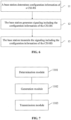
- FIG. 7 is a schematic diagram of a device for configuring a CSI-RS according to an embodiment of the invention.
- the device for configuring the CSI-RS provided by the embodiment is arranged at a base station, and includes: a determination module 1101, a generation module 1102 and a transmission module 1103, wherein the determination module 1101 is arranged to determine configuration information of a CSI-RS; the generation module 1102 is arranged to generate signaling including the configuration information of the CSI-RS; and the transmission module 1103 is arranged to transmit the signaling including the configuration information of the CSI-RS, wherein the configuration information includes: a number of ports, RS resource pattern information and an inter-CSI-RS-port multiplexing scheme; and when the number of the ports is larger than 1, there exist M candidate RS resource patterns for the CSI-RS, where M is an integer greater than 1.
- the M candidate RS resource patterns include that: when the number of the ports is larger than a first threshold value, at least two inter-CSI-RS-port multiplexing schemes are used for the M candidate RS resource patterns.
- the M candidate RS resource patterns include that: the M candidate RS resource patterns are divided into two sets, a first multiplexing scheme is used for CSI-RS ports of the first pattern set, a second multiplexing scheme is used for CSI-RS ports of the second pattern set, and the first multiplexing scheme is different from the second multiplexing scheme.
- the M candidate RS resource patterns include that: the M candidate RS resource patterns are divided into two sets, a first multiplexing scheme is used for CSI-RS ports of the first pattern set, the first multiplexing scheme or a second multiplexing scheme is used for CSI-RS ports of the second pattern set, the first multiplexing scheme is different from the second multiplexing scheme, and the multiplexing scheme used for the CSI-RS ports of the second pattern set is configured via signaling of a base station.
- the M candidate RS resource patterns include that: the M candidate RS resource patterns are divided into three sets, a first multiplexing scheme is used for CSI-RS ports of the first pattern set, a second multiplexing scheme is used for CSI-RS ports of the second pattern set, the first multiplexing scheme or the second multiplexing scheme is used for CSI-RS ports of the third pattern set, the first multiplexing scheme is different from the second multiplexing scheme, and the multiplexing scheme used for the CSI-RS ports of the third pattern set is configured via signaling of the base station.
- the multiplexing scheme is a code division multiplexing scheme.
- the first code division multiplexing scheme is code division multiplexing with an orthogonal code length of 2
- the second code division multiplexing scheme is code division multiplexing with an orthogonal code length of 4.
- the M candidate RS resource patterns include that: when the number of the ports is larger than a second threshold value, at least two types of RS densities are used for the M candidate RS resource patterns.
- the M candidate RS resource patterns include that: the M candidate RS resource patterns are divided into two sets, a first type of RS density is used for the first pattern set, a second type of RS density is used for the second pattern set, and the first type of RS density is different from the second type of RS density.
- the M candidate RS resource patterns include that: in an RS resource pattern set, the inter-CSI-RS-port multiplexing scheme uses a code division multiplexing length of 4, and four REs for mapping of code division multiplexed RS symbols of each group are located on two continuous subcarriers.
- the M candidate RS resource patterns include that: a maximum frequency interval of REs on a PRB pair in a pattern of which an RS density is one RE in each PRB pair for each port is less than or equal to the number, which is a third threshold value, of subcarriers, and the maximum frequency interval is a difference between a highest frequency and a lowest frequency of frequency bands in which the REs are located.
- the third threshold value is 9.
- the M candidate RS resource patterns include that: a maximum time-domain interval of REs on each RS resource pattern is smaller than a fourth threshold value, wherein the maximum time-domain interval is a difference value between a last one and a first one of OFDM symbols in which the REs are located.
- the fourth threshold value is 6.
- the fourth threshold value is 5.
- the M candidate RS resource patterns include that: when the number of the ports is 12, in an RS resource pattern set, each RS resource pattern corresponds to an RS resource pattern under a number of ports of 8, moreover, an RS density is two REs in every three PRB pairs for each port, and different RS resource patterns correspond to different RS resource patterns under the number of the ports of 8.
- the M candidate RS resource patterns include that: when the number of the ports is 12, in an RS resource pattern set, each RS resource pattern corresponds to an RS resource pattern under a number of ports of 4 and an RS resource pattern under a number of ports of 2 and is on the same two OFDM symbols, an RS density is one RE in every two PRB pairs for each port, and different RS resource patterns correspond to combinations of different RS resource patterns under the number of the ports of 4 and RS resource patterns under the number of the ports of 2.
- the M candidate RS resource patterns include that: when the number of the ports is 12, in an RS resource pattern set, each RS resource pattern corresponds to an RS resource pattern under a number of ports of 8 and two RS resource patterns under a number of ports of 2, moreover, the two RS resource patterns under the two port numbers are located on the same two OFDM symbols and adjacent on a frequency domain, an RS density is one RE in each PRB pair for each port, and different RS resource patterns correspond to combinations of different RS resource patterns under the number of the ports of 8 and RS resource patterns under the number of the ports of 2.
- the M candidate RS resource patterns include that: when the number of the ports is 12, in an RS resource pattern set, each RS resource pattern corresponds to two groups of ports, a first code division multiplexing scheme is used for the first group of ports, a second code division multiplexing scheme is used for the second group of ports, and the first code division multiplexing scheme is different from the second code division multiplexing scheme.
- the M candidate RS resource patterns include that: in an RS resource pattern set, each RS resource pattern corresponds to two groups of ports, a first code division multiplexing scheme is used for the first group of ports, the first code division multiplexing scheme or a second code division multiplexing scheme is used for the second group of ports, the first code division multiplexing scheme is different from the second code division multiplexing scheme, and the code division multiplexing scheme used for the second group of ports is configured via signaling of the base station.
- the M candidate RS resource patterns include that: in an RS resource pattern set, each RS resource pattern corresponds to two groups of ports, a first code division multiplexing scheme or a second code division multiplexing scheme is used for the first group of ports, the first code division multiplexing scheme or the second code division multiplexing scheme is used for the second group of ports, the first code division multiplexing scheme is different from the second code division multiplexing scheme, the code division multiplexing scheme used for the first group of ports is configured via signaling of the base station, and the code division multiplexing scheme used for the second group of ports is configured by the signaling of the base station.
- the M candidate RS resource patterns include that: in an RS resource pattern set, the inter-CSI-RS-port multiplexing scheme uses a code division multiplexing length of 4, and code division multiplexed RS symbols of each group are mapped to REs on a PRB pair in a resource pattern under the number of the ports of 4.
- the determination module is arranged to determine the configuration information of the CSI-RS includes that: when the inter-CSI-RS-port multiplexing scheme uses the code division multiplexing length of 4 and the ports are grouped for code division multiplexing, a port grouping manner is configured via signaling of the base station, the port grouping manner including two types.
- the M candidate RS resource patterns include that: the M candidate RS resource patterns are divided into two sets, a first port grouping manner is used for CSI-RS ports of the first pattern set, a second port grouping manner is used for CSI-RS ports of the second pattern set, and the first port grouping manner is different from the second port grouping manner.
- the transmission module is a communication component with an information transmission capability, for example, a transmitter
- the determination module and the generation module are components with an information processing capability, for example, a processor.
- the modules may be, for example, combinations of software and/or hardware capable of realizing certain functions.
- a bits may be used to represent the port number information
- b bits are used to represent the RS resource pattern information
- the RS resource pattern information prompts the inter-CSI-RS-port multiplexing scheme.
- the M candidate RS resource patterns are divided into two sets, a first multiplexing scheme is used for CSI-RS ports of the first pattern set, a second multiplexing scheme is used for CSI-RS ports of the second pattern ports, and the first multiplexing scheme is different from the second multiplexing scheme, wherein M is an integer greater than 1.
- the M candidate RS resource patterns are divided into two sets, a first multiplexing scheme is used for CSI-RS ports of the first pattern set, the first multiplexing scheme or a second multiplexing scheme is used for CSI-RS ports of the second pattern set, and the first multiplexing scheme is different from the second multiplexing scheme, where M is an integer greater than 1.
- the multiplexing scheme used for the CSI-RS ports of the second pattern set is configured via signaling of the base station.
- the first code division multiplexing scheme used for the CSI-RS ports of the first pattern sets uses a code division multiplexing length of 2, and the code division multiplexing scheme used for the CSI-RS ports of the second pattern set uses a code division multiplexing length of 2 or 4; or the first code division multiplexing scheme used for the CSI-RS ports of the first pattern set uses the code division multiplexing length of 4, and the code division multiplexing scheme used for the CSI-RS ports of the second pattern set uses the code division multiplexing length of 2 or 4, where the code division multiplexing length used for the CSI-RS ports of the second pattern set is configured via signaling of the base station.
- the M candidate RS resource patterns are divided into three sets, a first multiplexing scheme is used for CSI-RS ports of the first pattern set, a second multiplexing scheme is used for CSI-RS ports of the second pattern set, the first multiplexing scheme or the second multiplexing scheme is used for CSI-RS ports of the third pattern set, and the first multiplexing scheme is different from the second multiplexing scheme, where M is an integer greater than 1.
- the multiplexing scheme used for the CSI-RS ports of the third pattern set is configured via signaling of the base station.
- a second threshold value TH2
- M is an integer greater than 1.
- the M candidate RS resource patterns are divided into two sets, a first type of RS density is used for the first pattern set, a second type of RS density is used for the second pattern set, and the first type of RS density is different from the second type of RS density, where M is an integer greater than 1.
- the RS density used for the first pattern set is one RE in each PRB pair for each port
- the RS density used for the second pattern set is one RE in every two PRB pairs for each port
- the RS density used for the first pattern set is one RE in every two PRB pairs for each port
- the RS density used for the second pattern set is one RE in each PRB pair for each port.
- the inter-CSI-RS-port multiplexing scheme uses a code division multiplexing length of 4, and four REs for mapping of each group of code division multiplexed RS symbols are located on two continuous subcarriers.
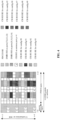
- CSI-RS RE for config #0 CSI-RS RE for config #1
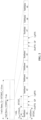
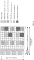
- the 16 ports are divided into four groups: ⁇ 15, 16, 17, 18 ⁇ , ⁇ 19, 20, 21, 22 ⁇ , ⁇ 23, 24, 25, 26 ⁇ and ⁇ 27, 28, 29, 30 ⁇ , and the four REs for code division multiplexing mapping of the ports of each group are located on two continuous subcarriers.
- each group of the CSI-RSs are code division multiplexed to four REs of continuous subcarriers
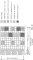
- there are three RS resource patterns in FIG. 9 i.e., CSI-RS RE for config #0, CSI-RS RE for config #1 and CSI-RS RE for config #2, and in each RS resource pattern, the 12 ports are divided into three groups: ⁇ 15, 16, 17, 18 ⁇ , ⁇ 19, 20, 21, 22 ⁇ and ⁇ 23, 24, 25, 26 ⁇ , and the four REs for code division multiplexing mapping of the ports of each group are located on two continuous subcarriers.
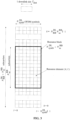
- a maximum frequency interval of REs on a PRB pair in a pattern of which an RS density is one RE in each PRB pair for each port is not larger than (namely, less than or equal to) the number, which is a third threshold value (TH3), of subcarriers, that is, the maximum frequency interval is a difference between a highest frequency and a lowest frequency of frequency bands in which the REs are located.
- TH3 third threshold value
- the third threshold value is 9.
- FIG. 10 is a pattern with a maximum frequency interval of not larger than 9 on a PRB pair in the case that an RS density is one RE in each PRB pair for each port.
- a maximum time-domain interval of REs on each RS resource pattern is smaller than a fourth threshold value (TH4), and the maximum time-domain interval is a difference value between a last one and a first one of OFDM symbols in which the REs are located.
- TH4 fourth threshold value
- the fourth threshold value is 6.
- FIG. 11 is a pattern with a maximum time-domain interval smaller than 6.
- the fourth threshold value is 5.
- each RS resource pattern corresponds to two groups of ports, a first code division multiplexing scheme is used for the first group of ports, the first code division multiplexing scheme or a second code division multiplexing scheme is used for the second group of ports, and the first code division multiplexing scheme is different from the second code division multiplexing scheme.
- the code division multiplexing scheme used for the second group of ports is configured via signaling of the base station.
- each RS resource pattern corresponds to two groups of ports, a first code division multiplexing scheme or a second code division multiplexing scheme is used for the first group of ports, the first code division multiplexing scheme or the second code division multiplexing scheme is used for the second group of ports, and the first code division multiplexing scheme is different from the second code division multiplexing scheme.
- the code division multiplexing scheme used for the first group of ports is configured via signaling of the base station, and the code division multiplexing scheme used for the second group of ports is configured by the signaling of the base station.
- the M candidate RS resource patterns are divided into two sets.
- a first pattern set code division multiplexed RS symbols in a same group are mapped to REs in a first mapping manner; and in a second pattern set, a second mapping manner is used to map code division multiplexed RS symbols in a same group to REs, and the first mapping manner is different from the second mapping manner, wherein M is an integer greater than 1.
- An embodiment of the invention further provides a storage medium.
- the storage medium may be arranged to store program codes arranged to execute the following operations.
- the signaling including the configuration information of the CSI-RS is transmitted.
Landscapes
- Engineering & Computer Science (AREA)
- Signal Processing (AREA)
- Computer Networks & Wireless Communication (AREA)
- Mobile Radio Communication Systems (AREA)
- Circuits Of Receivers In General (AREA)
Claims (9)
- Procédé de configuration d'un signal de référence d'information sur l'état du canal, CSI-RS, consistant à: déterminer (11), par une station de base, les informations de configuration du CSI-RS; générer (12), par la station de base, une signalisation comprenant les informations de configuration du CSI-RS; et transmettre (13), par la station de base, la signalisation contenant les informations de configuration du CSI-RS, dans lequel les informations de configuration comprennent: un nombre de ports CSI-RS, des informations sur le modèle de ressource CSI-RS et un schéma de multiplexage inter-ports CSI-RS; et lorsque le nombre de ports CSI-RS est supérieur à 1, le CSI-RS a M modèles de ressource CSI-RS candidats, chaque modèle de ressource CSI-RS est avec le nombre de ports CSI-RS, où M est un entier supérieur à 1; dans lequel les M motifs de ressources CSI-RS candidats sont divisés en un premier ensemble de motifs et un second ensemble de motifs, un premier schéma de multiplexage de division de code avec une longueur de code orthogonal de 2 est utilisé pour les ports CSI-RS de chaque motif de ressource CSI-RS dans le premier ensemble de motifs, un second schéma de multiplexage de division de code avec une longueur de code orthogonal de 4 est utilisé pour les ports CSI-RS de chaque motif de ressource CSI-RS dans le second ensemble de motifs, et le premier schéma de multiplexage de division de code est différent du second schéma de multiplexage de division de code.
- Procédé selon la revendication 1, dans lequel, lorsque le nombre de ports CSI-RS est supérieur à une deuxième valeur seuil, au moins deux types de densités RS sont utilisés pour les M schémas de ressources CSI-RS candidats.
- Procédé selon la revendication 1, dans lequel, dans un ensemble de modèles de ressources CSI-RS, le schéma de multiplexage inter-CSI-RS-port utilise une longueur de multiplexage par division de code de 4, et quatre éléments de ressource, RE, auxquels chaque groupe de symboles RS multiplexés par division de code est mappé, sont situés sur deux sous-porteuses continues.
- Procédé selon la revendication 1, dans lequel, dans le premier ensemble de motifs, les symboles RS multiplexés par division de code d'un même groupe sont mis en correspondance avec les RE d'une première manière; dans le deuxième ensemble de motifs, les symboles RS multiplexés par division de code d'un même groupe sont mis en correspondance avec les RE d'une deuxième manière, et la première manière est différente de la deuxième.
- Procédé selon la revendication 1, dans lequel un premier mode de regroupement des ports est utilisé pour les ports CSI-RS du premier ensemble de motifs, un deuxième mode de regroupement des ports est utilisé pour les ports CSI-RS du deuxième ensemble de motifs, et le premier mode de regroupement des ports est différent du deuxième mode de regroupement des ports.
- Appareil permettant de configurer un signal de référence d'information sur l'état du canal, CSI-RS, comprenant: un module de détermination (1101), conçu pour déterminer les informations de configuration du CSI-RS; un module de génération (1102), conçu pour générer une signalisation comprenant les informations de configuration du CSI-RS; et un module de transmission (1103), conçu pour transmettre la signalisation comprenant les informations de configuration du CSI-RS, dans lequel les informations de configuration comprennent: un nombre de ports CSI-RS, des informations sur le modèle de ressources CSI-RS et un schéma de multiplexage entre ports CSI-RS; et lorsque le nombre de ports CSI-RS est supérieur à 1, le CSI-RS a M modèles de ressources RS candidats, chaque modèle de ressources CSI-RS étant associé au nombre de ports CSI-RS, M étant un nombre entier supérieur à 1; dans lequel les M motifs de ressources CSI-RS candidats sont divisés en un premier ensemble de motifs et un second ensemble de motifs, un premier schéma de multiplexage de division de code avec une longueur de code orthogonal de 2 est utilisé pour les ports CSI-RS de chaque motif de ressource CSI-RS dans le premier ensemble de motifs, un second schéma de multiplexage de division de code avec une longueur de code orthogonal de 4 est utilisé pour les ports CSI-RS de chaque motif de ressource CSI-RS dans le second ensemble de motifs, et le premier schéma de multiplexage de division de code est différent du second schéma de multiplexage de division de code.
- Dispositif selon la revendication 6, dans lequel, lorsque le nombre de ports CSI-RS est supérieur à une deuxième valeur seuil, au moins deux types de densités RS sont utilisés pour les M modèles de ressources CSI-RS candidats.
- Dispositif selon la revendication 6, dans lequel, dans un ensemble de modèles de ressources CSI-RS, le schéma de multiplexage inter-CSI-RS-port utilise la longueur de multiplexage par division de code de 4, et quatre éléments de ressource, RE, auxquels chaque groupe de symboles RS multiplexés par division de code est mappé, sont situés sur deux sous-porteuses continues.
- Dispositif selon la revendication 6, dans lequel l'un des points i) ou ii) s'applique:i) dans le premier jeu de motifs, les symboles RS multiplexés par division de code d'un même groupe sont mis en correspondance avec les RE d'une première manière; dans le second jeu de motifs, les symboles RS multiplexés par division de code d'un même groupe sont mis en correspondance avec les RE d'une seconde manière, et la première manière de mise en correspondance est différente de la seconde;ii) une première méthode de regroupement des ports est utilisée pour les ports CSI-RS du premier ensemble de motifs, une deuxième méthode de regroupement des ports est utilisée pour les ports CSI-RS du deuxième ensemble de motifs, et la première méthode de regroupement des ports est différente de la deuxième méthode de regroupement des ports.
Priority Applications (1)
| Application Number | Priority Date | Filing Date | Title |
|---|---|---|---|
| EP25178030.0A EP4583432A3 (fr) | 2015-09-25 | 2016-08-16 | Procédé et appareil de réception de signalisation, et support de stockage lisible par ordinateur |
Applications Claiming Priority (2)
| Application Number | Priority Date | Filing Date | Title |
|---|---|---|---|
| CN201510624664.XA CN106559199A (zh) | 2015-09-25 | 2015-09-25 | 一种配置信道状态测量导频的方法及装置 |
| PCT/CN2016/095499 WO2017050065A1 (fr) | 2015-09-25 | 2016-08-16 | Procédé et appareil de configuration de signal de référence d'informations d'état de canal |
Related Child Applications (2)
| Application Number | Title | Priority Date | Filing Date |
|---|---|---|---|
| EP25178030.0A Division EP4583432A3 (fr) | 2015-09-25 | 2016-08-16 | Procédé et appareil de réception de signalisation, et support de stockage lisible par ordinateur |
| EP25178030.0A Division-Into EP4583432A3 (fr) | 2015-09-25 | 2016-08-16 | Procédé et appareil de réception de signalisation, et support de stockage lisible par ordinateur |
Publications (4)
| Publication Number | Publication Date |
|---|---|
| EP3355507A1 EP3355507A1 (fr) | 2018-08-01 |
| EP3355507A4 EP3355507A4 (fr) | 2018-12-26 |
| EP3355507C0 EP3355507C0 (fr) | 2025-07-09 |
| EP3355507B1 true EP3355507B1 (fr) | 2025-07-09 |
Family
ID=58385837
Family Applications (2)
| Application Number | Title | Priority Date | Filing Date |
|---|---|---|---|
| EP25178030.0A Pending EP4583432A3 (fr) | 2015-09-25 | 2016-08-16 | Procédé et appareil de réception de signalisation, et support de stockage lisible par ordinateur |
| EP16847947.5A Active EP3355507B1 (fr) | 2015-09-25 | 2016-08-16 | Procédé et appareil de configuration de signal de référence d'informations d'état de canal |
Family Applications Before (1)
| Application Number | Title | Priority Date | Filing Date |
|---|---|---|---|
| EP25178030.0A Pending EP4583432A3 (fr) | 2015-09-25 | 2016-08-16 | Procédé et appareil de réception de signalisation, et support de stockage lisible par ordinateur |
Country Status (4)
| Country | Link |
|---|---|
| US (2) | US11233611B2 (fr) |
| EP (2) | EP4583432A3 (fr) |
| CN (1) | CN106559199A (fr) |
| WO (1) | WO2017050065A1 (fr) |
Families Citing this family (16)
| Publication number | Priority date | Publication date | Assignee | Title |
|---|---|---|---|---|
| CN106685620B (zh) * | 2015-11-06 | 2021-02-12 | 中兴通讯股份有限公司 | 信道状态测量导频的配置方法及装置、解析方法及装置 |
| EP3520303B1 (fr) * | 2016-09-28 | 2021-01-13 | NTT DoCoMo, Inc. | Procédé de communication sans fil pour transmettre une indication de ressource de signal de référence |
| CN109716797A (zh) * | 2016-09-29 | 2019-05-03 | 华为技术有限公司 | 信道状态信息参考信号发送方法与接收方法及设备 |
| US10931418B2 (en) * | 2016-09-30 | 2021-02-23 | Telefonaktiebolaget Lm Ericsson (Publ) | CDM8 based CSI-RS designs for MIMO |
| CN108023699B (zh) * | 2016-11-04 | 2020-12-15 | 华为技术有限公司 | 信号传输方法和装置 |
| CN108400851B (zh) * | 2017-02-04 | 2022-08-19 | 中兴通讯股份有限公司 | 配置信息处理方法及装置、基站、终端 |
| CN108111269B (zh) * | 2017-05-05 | 2023-01-10 | 中兴通讯股份有限公司 | 一种信道状态信息导频传输方法与装置 |
| WO2019024055A1 (fr) * | 2017-08-03 | 2019-02-07 | Nec Corporation | Procédé et appareil de configuration de signal de référence |
| CN109391391B (zh) * | 2017-08-08 | 2020-04-17 | 维沃移动通信有限公司 | 一种用于传输参考信号的方法及装置 |
| CN109391411B (zh) * | 2017-08-10 | 2021-03-02 | 电信科学技术研究院 | 一种导频配置方法、信道测量方法及通信设备 |
| CN108111273B (zh) * | 2017-08-11 | 2021-11-02 | 中兴通讯股份有限公司 | 参考信号的传输方法及装置 |
| CN110071749B (zh) * | 2018-01-22 | 2021-08-31 | 华为技术有限公司 | 一种天线选择指示方法、装置和系统 |
| US12155590B2 (en) | 2018-11-01 | 2024-11-26 | Nec Corporation | Reference signal transmission |
| US11665711B2 (en) * | 2019-10-04 | 2023-05-30 | Qualcomm Incorporated | Decoding physical multicast channel subframes according to different reference signal patterns |
| US20240187186A1 (en) * | 2021-03-30 | 2024-06-06 | Ntt Docomo, Inc. | Terminal, radio communication method, and base station |
| CN115606295A (zh) | 2021-03-31 | 2023-01-13 | 苹果公司(Us) | 对参考信号的资源计数 |
Family Cites Families (18)
| Publication number | Priority date | Publication date | Assignee | Title |
|---|---|---|---|---|
| CN101841817B (zh) * | 2009-03-20 | 2013-09-11 | 中兴通讯股份有限公司 | 一种信道测量导频的配置方法 |
| CN102195741A (zh) * | 2010-03-10 | 2011-09-21 | 华为技术有限公司 | 信道状态信息参考信号的传输方法和装置 |
| CN101834629B (zh) * | 2010-04-06 | 2014-10-22 | 中兴通讯股份有限公司 | 一种指示传输参数的方法及系统 |
| CN102237951B (zh) | 2010-04-30 | 2014-03-05 | 中国移动通信集团公司 | 小区八天线端口的信道状态信息参考信号传输方法和设备 |
| CN103763070B (zh) * | 2010-08-02 | 2015-03-25 | 华为技术有限公司 | 通知参考信号配置信息的方法及设备 |
| CN103763071B (zh) | 2010-08-02 | 2017-04-12 | 华为技术有限公司 | 通知参考信号配置信息的方法及设备 |
| EP2603990B1 (fr) * | 2010-08-13 | 2019-10-02 | LG Electronics Inc. | Procédé et station de base pour transmettre un signal de liaison descendante et procédé et équipement pour recevoir un signal de liaison descendante |
| CN102378114B (zh) | 2010-08-16 | 2014-06-11 | 中国移动通信集团公司 | 信道状态信息参考信号发送方法及装置、接收方法及装置 |
| CN102480342A (zh) * | 2010-11-25 | 2012-05-30 | 普天信息技术研究院有限公司 | 一种传输参考信号的方法和系统 |
| JP6104812B2 (ja) * | 2010-12-03 | 2017-03-29 | サムスン エレクトロニクス カンパニー リミテッド | 分散アンテナシステムでレファレンス信号割り当て及びチャネル推定のための方法及び装置 |
| US9252930B2 (en) | 2011-01-07 | 2016-02-02 | Futurewei Technologies, Inc. | Reference signal transmission and reception method and equipment |
| CN102638432B (zh) * | 2011-02-12 | 2016-09-28 | 中兴通讯股份有限公司 | 空频块状编码的资源映射方法和装置 |
| CN102315870B (zh) * | 2011-09-30 | 2017-10-03 | 中兴通讯股份有限公司 | 一种下行控制信息指示方法及装置 |
| US9509377B2 (en) * | 2011-11-07 | 2016-11-29 | Google Technology Holdings LLC | Method and apparatus for rank adaptation in an orthogonal frequency division multiplexing communication system |
| KR20150009566A (ko) * | 2012-05-08 | 2015-01-26 | 마벨 월드 트레이드 리미티드 | 협력 다중포인트 전송에서 피드백을 보고하기 위한 방법 및 시스템 |
| US9191943B2 (en) * | 2012-09-13 | 2015-11-17 | Kt Corporation | Reception and configuration of downlink control channel |
| CN104125037B (zh) * | 2013-04-25 | 2018-10-26 | 中兴通讯股份有限公司 | 参考信号配置信息的处理方法、装置和系统 |
| CN112865847B (zh) * | 2015-04-10 | 2023-09-12 | Lg 电子株式会社 | 在无线通信系统中报告信道状态信息的方法及其设备 |
-
2015
- 2015-09-25 CN CN201510624664.XA patent/CN106559199A/zh active Pending
-
2016
- 2016-08-16 EP EP25178030.0A patent/EP4583432A3/fr active Pending
- 2016-08-16 WO PCT/CN2016/095499 patent/WO2017050065A1/fr not_active Ceased
- 2016-08-16 EP EP16847947.5A patent/EP3355507B1/fr active Active
- 2016-08-16 US US15/762,059 patent/US11233611B2/en active Active
-
2021
- 2021-12-13 US US17/548,674 patent/US12021778B2/en active Active
Non-Patent Citations (2)
| Title |
|---|
| "3rd Generation Partnership Project; Technical Specification Group Radio Access Network; Evolved Universal Terrestrial Radio Access (E-UTRA); Physical channels and modulation (Release 12)", 3GPP STANDARD; 3GPP TS 36.211, 3RD GENERATION PARTNERSHIP PROJECT (3GPP), MOBILE COMPETENCE CENTRE ; 650, ROUTE DES LUCIOLES ; F-06921 SOPHIA-ANTIPOLIS CEDEX ; FRANCE, vol. RAN WG1, no. V12.6.0, 24 June 2015 (2015-06-24), pages 1 - 136, XP050965905 * |
| ZTE: "Extension of Non-Precoded CSI-RS for 12 and 16 Ports", vol. RAN WG1, no. Malmö, Sweden; 20151005 - 20151009, 4 October 2015 (2015-10-04), XP051002222, Retrieved from the Internet <URL:http://www.3gpp.org/ftp/Meetings_3GPP_SYNC/RAN1/Docs/> [retrieved on 20151004] * |
Also Published As
| Publication number | Publication date |
|---|---|
| US12021778B2 (en) | 2024-06-25 |
| EP4583432A2 (fr) | 2025-07-09 |
| US11233611B2 (en) | 2022-01-25 |
| EP4583432A3 (fr) | 2025-10-01 |
| EP3355507A4 (fr) | 2018-12-26 |
| EP3355507C0 (fr) | 2025-07-09 |
| EP3355507A1 (fr) | 2018-08-01 |
| US20220103326A1 (en) | 2022-03-31 |
| WO2017050065A1 (fr) | 2017-03-30 |
| CN106559199A (zh) | 2017-04-05 |
| US20180270032A1 (en) | 2018-09-20 |
Similar Documents
| Publication | Publication Date | Title |
|---|---|---|
| US12021778B2 (en) | Method and apparatus for receiving signal | |
| US11483117B2 (en) | Method and device for configuring channel state information reference signal, and method and device for parsing configuring channel state information reference signal | |
| US9930651B2 (en) | Downlink control information configuration and acquisition method, base station and terminal | |
| JP6118382B2 (ja) | 参照信号受信方法及びユーザー機器、参照信号伝送方法及び基地局 | |
| CN106685503B (zh) | 信道状态测量导频csi-rs的配置方法及装置 | |
| CN102638892B (zh) | 一种对e-pdcch进行资源映射的方法及装置 | |
| EP3522579A1 (fr) | Transmission de canal de commande et procédé de réception et système | |
| CN104081707A (zh) | 用于生成和传输解调参考信号的方法 | |
| CN105557046B (zh) | 导频信号的传输方法及装置 | |
| WO2017167158A1 (fr) | Procédé et dispositif destinés à transmettre des informations de configuration pilote, et système | |
| US11646775B2 (en) | Information processing method and device, and storage medium | |
| KR20170061129A (ko) | Fdr 전송을 지원하는 무선 통신 시스템에서 디바이스 간 간섭을 측정하는 방법 및 이를 위한 장치 | |
| CN108400851B (zh) | 配置信息处理方法及装置、基站、终端 | |
| WO2019158036A1 (fr) | Procédé et appareil permettant de déterminer un motif de signal de référence |
Legal Events
| Date | Code | Title | Description |
|---|---|---|---|
| STAA | Information on the status of an ep patent application or granted ep patent |
Free format text: STATUS: THE INTERNATIONAL PUBLICATION HAS BEEN MADE |
|
| PUAI | Public reference made under article 153(3) epc to a published international application that has entered the european phase |
Free format text: ORIGINAL CODE: 0009012 |
|
| STAA | Information on the status of an ep patent application or granted ep patent |
Free format text: STATUS: REQUEST FOR EXAMINATION WAS MADE |
|
| 17P | Request for examination filed |
Effective date: 20180410 |
|
| AK | Designated contracting states |
Kind code of ref document: A1 Designated state(s): AL AT BE BG CH CY CZ DE DK EE ES FI FR GB GR HR HU IE IS IT LI LT LU LV MC MK MT NL NO PL PT RO RS SE SI SK SM TR |
|
| AX | Request for extension of the european patent |
Extension state: BA ME |
|
| A4 | Supplementary search report drawn up and despatched |
Effective date: 20181126 |
|
| RIC1 | Information provided on ipc code assigned before grant |
Ipc: H04L 25/02 20060101ALI20181120BHEP Ipc: H04L 1/06 20060101ALI20181120BHEP Ipc: H04L 5/00 20060101AFI20181120BHEP Ipc: H04J 13/00 20110101ALI20181120BHEP Ipc: H04B 7/06 20060101ALI20181120BHEP Ipc: H04L 27/26 20060101ALI20181120BHEP |
|
| DAV | Request for validation of the european patent (deleted) | ||
| DAX | Request for extension of the european patent (deleted) | ||
| STAA | Information on the status of an ep patent application or granted ep patent |
Free format text: STATUS: EXAMINATION IS IN PROGRESS |
|
| 17Q | First examination report despatched |
Effective date: 20191024 |
|
| GRAP | Despatch of communication of intention to grant a patent |
Free format text: ORIGINAL CODE: EPIDOSNIGR1 |
|
| STAA | Information on the status of an ep patent application or granted ep patent |
Free format text: STATUS: GRANT OF PATENT IS INTENDED |
|
| RIC1 | Information provided on ipc code assigned before grant |
Ipc: H04L 25/02 20060101ALN20250121BHEP Ipc: H04B 7/06 20060101ALN20250121BHEP Ipc: H04J 13/00 20110101ALI20250121BHEP Ipc: H04L 5/00 20060101AFI20250121BHEP |
|
| INTG | Intention to grant announced |
Effective date: 20250206 |
|
| GRAS | Grant fee paid |
Free format text: ORIGINAL CODE: EPIDOSNIGR3 |
|
| GRAA | (expected) grant |
Free format text: ORIGINAL CODE: 0009210 |
|
| STAA | Information on the status of an ep patent application or granted ep patent |
Free format text: STATUS: THE PATENT HAS BEEN GRANTED |
|
| AK | Designated contracting states |
Kind code of ref document: B1 Designated state(s): AL AT BE BG CH CY CZ DE DK EE ES FI FR GB GR HR HU IE IS IT LI LT LU LV MC MK MT NL NO PL PT RO RS SE SI SK SM TR |
|
| REG | Reference to a national code |
Ref country code: GB Ref legal event code: FG4D |
|
| REG | Reference to a national code |
Ref country code: CH Ref legal event code: EP |
|
| REG | Reference to a national code |
Ref country code: IE Ref legal event code: FG4D |
|
| REG | Reference to a national code |
Ref country code: DE Ref legal event code: R096 Ref document number: 602016092865 Country of ref document: DE |
|
| U01 | Request for unitary effect filed |
Effective date: 20250806 |
|
| U07 | Unitary effect registered |
Designated state(s): AT BE BG DE DK EE FI FR IT LT LU LV MT NL PT RO SE SI Effective date: 20250818 |
|
| U20 | Renewal fee for the european patent with unitary effect paid |
Year of fee payment: 10 Effective date: 20250826 |
|
| PGFP | Annual fee paid to national office [announced via postgrant information from national office to epo] |
Ref country code: GB Payment date: 20250826 Year of fee payment: 10 |
|
| PG25 | Lapsed in a contracting state [announced via postgrant information from national office to epo] |
Ref country code: IS Free format text: LAPSE BECAUSE OF FAILURE TO SUBMIT A TRANSLATION OF THE DESCRIPTION OR TO PAY THE FEE WITHIN THE PRESCRIBED TIME-LIMIT Effective date: 20251109 |
|
| PG25 | Lapsed in a contracting state [announced via postgrant information from national office to epo] |
Ref country code: NO Free format text: LAPSE BECAUSE OF FAILURE TO SUBMIT A TRANSLATION OF THE DESCRIPTION OR TO PAY THE FEE WITHIN THE PRESCRIBED TIME-LIMIT Effective date: 20251009 |
|
| PG25 | Lapsed in a contracting state [announced via postgrant information from national office to epo] |
Ref country code: HR Free format text: LAPSE BECAUSE OF FAILURE TO SUBMIT A TRANSLATION OF THE DESCRIPTION OR TO PAY THE FEE WITHIN THE PRESCRIBED TIME-LIMIT Effective date: 20250709 |
|
| PG25 | Lapsed in a contracting state [announced via postgrant information from national office to epo] |
Ref country code: GR Free format text: LAPSE BECAUSE OF FAILURE TO SUBMIT A TRANSLATION OF THE DESCRIPTION OR TO PAY THE FEE WITHIN THE PRESCRIBED TIME-LIMIT Effective date: 20251010 |
|
| PG25 | Lapsed in a contracting state [announced via postgrant information from national office to epo] |
Ref country code: PL Free format text: LAPSE BECAUSE OF FAILURE TO SUBMIT A TRANSLATION OF THE DESCRIPTION OR TO PAY THE FEE WITHIN THE PRESCRIBED TIME-LIMIT Effective date: 20250709 |
|
| PG25 | Lapsed in a contracting state [announced via postgrant information from national office to epo] |
Ref country code: RS Free format text: LAPSE BECAUSE OF FAILURE TO SUBMIT A TRANSLATION OF THE DESCRIPTION OR TO PAY THE FEE WITHIN THE PRESCRIBED TIME-LIMIT Effective date: 20251009 |
|
| PG25 | Lapsed in a contracting state [announced via postgrant information from national office to epo] |
Ref country code: ES Free format text: LAPSE BECAUSE OF FAILURE TO SUBMIT A TRANSLATION OF THE DESCRIPTION OR TO PAY THE FEE WITHIN THE PRESCRIBED TIME-LIMIT Effective date: 20250709 |
|
| REG | Reference to a national code |
Ref country code: CH Ref legal event code: H13 Free format text: ST27 STATUS EVENT CODE: U-0-0-H10-H13 (AS PROVIDED BY THE NATIONAL OFFICE) Effective date: 20260324 |
|
| PG25 | Lapsed in a contracting state [announced via postgrant information from national office to epo] |
Ref country code: SM Free format text: LAPSE BECAUSE OF FAILURE TO SUBMIT A TRANSLATION OF THE DESCRIPTION OR TO PAY THE FEE WITHIN THE PRESCRIBED TIME-LIMIT Effective date: 20250709 |
|
| PG25 | Lapsed in a contracting state [announced via postgrant information from national office to epo] |
Ref country code: CZ Free format text: LAPSE BECAUSE OF FAILURE TO SUBMIT A TRANSLATION OF THE DESCRIPTION OR TO PAY THE FEE WITHIN THE PRESCRIBED TIME-LIMIT Effective date: 20250709 Ref country code: CH Free format text: LAPSE BECAUSE OF NON-PAYMENT OF DUE FEES Effective date: 20250831 |
|
| PG25 | Lapsed in a contracting state [announced via postgrant information from national office to epo] |
Ref country code: SK Free format text: LAPSE BECAUSE OF FAILURE TO SUBMIT A TRANSLATION OF THE DESCRIPTION OR TO PAY THE FEE WITHIN THE PRESCRIBED TIME-LIMIT Effective date: 20250709 |