EP3356112B1 - Gewindeform mit trennsystem - Google Patents
Gewindeform mit trennsystem Download PDFInfo
- Publication number
- EP3356112B1 EP3356112B1 EP16852591.3A EP16852591A EP3356112B1 EP 3356112 B1 EP3356112 B1 EP 3356112B1 EP 16852591 A EP16852591 A EP 16852591A EP 3356112 B1 EP3356112 B1 EP 3356112B1
- Authority
- EP
- European Patent Office
- Prior art keywords
- unscrewing
- elevator
- assembly
- threaded
- driving
- Prior art date
- Legal status (The legal status is an assumption and is not a legal conclusion. Google has not performed a legal analysis and makes no representation as to the accuracy of the status listed.)
- Active
Links
Images






Classifications
-
- B—PERFORMING OPERATIONS; TRANSPORTING
- B29—WORKING OF PLASTICS; WORKING OF SUBSTANCES IN A PLASTIC STATE IN GENERAL
- B29C—SHAPING OR JOINING OF PLASTICS; SHAPING OF MATERIAL IN A PLASTIC STATE, NOT OTHERWISE PROVIDED FOR; AFTER-TREATMENT OF THE SHAPED PRODUCTS, e.g. REPAIRING
- B29C45/00—Injection moulding, i.e. forcing the required volume of moulding material through a nozzle into a closed mould; Apparatus therefor
- B29C45/17—Component parts, details or accessories; Auxiliary operations
- B29C45/26—Moulds
- B29C45/2618—Moulds having screw-threaded mould walls
- B29C45/262—Moulds having screw-threaded mould walls provided with unscrewing drive means
-
- B—PERFORMING OPERATIONS; TRANSPORTING
- B29—WORKING OF PLASTICS; WORKING OF SUBSTANCES IN A PLASTIC STATE IN GENERAL
- B29C—SHAPING OR JOINING OF PLASTICS; SHAPING OF MATERIAL IN A PLASTIC STATE, NOT OTHERWISE PROVIDED FOR; AFTER-TREATMENT OF THE SHAPED PRODUCTS, e.g. REPAIRING
- B29C33/00—Moulds or cores; Details thereof or accessories therefor
- B29C33/44—Moulds or cores; Details thereof or accessories therefor with means for, or specially constructed to facilitate, the removal of articles, e.g. of undercut articles
- B29C33/442—Moulds or cores; Details thereof or accessories therefor with means for, or specially constructed to facilitate, the removal of articles, e.g. of undercut articles with mechanical ejector or drive means therefor
- B29C33/444—Moulds or cores; Details thereof or accessories therefor with means for, or specially constructed to facilitate, the removal of articles, e.g. of undercut articles with mechanical ejector or drive means therefor for stripping articles from a mould core, e.g. using stripper plates
- B29C33/446—Moulds or cores; Details thereof or accessories therefor with means for, or specially constructed to facilitate, the removal of articles, e.g. of undercut articles with mechanical ejector or drive means therefor for stripping articles from a mould core, e.g. using stripper plates and using a rotating movement to unscrew articles
-
- B—PERFORMING OPERATIONS; TRANSPORTING
- B29—WORKING OF PLASTICS; WORKING OF SUBSTANCES IN A PLASTIC STATE IN GENERAL
- B29C—SHAPING OR JOINING OF PLASTICS; SHAPING OF MATERIAL IN A PLASTIC STATE, NOT OTHERWISE PROVIDED FOR; AFTER-TREATMENT OF THE SHAPED PRODUCTS, e.g. REPAIRING
- B29C43/00—Compression moulding, i.e. applying external pressure to flow the moulding material; Apparatus therefor
- B29C43/32—Component parts, details or accessories; Auxiliary operations
- B29C43/50—Removing moulded articles
-
- B—PERFORMING OPERATIONS; TRANSPORTING
- B29—WORKING OF PLASTICS; WORKING OF SUBSTANCES IN A PLASTIC STATE IN GENERAL
- B29C—SHAPING OR JOINING OF PLASTICS; SHAPING OF MATERIAL IN A PLASTIC STATE, NOT OTHERWISE PROVIDED FOR; AFTER-TREATMENT OF THE SHAPED PRODUCTS, e.g. REPAIRING
- B29C45/00—Injection moulding, i.e. forcing the required volume of moulding material through a nozzle into a closed mould; Apparatus therefor
- B29C45/17—Component parts, details or accessories; Auxiliary operations
- B29C45/26—Moulds
- B29C45/2681—Moulds with rotatable mould parts
-
- B—PERFORMING OPERATIONS; TRANSPORTING
- B29—WORKING OF PLASTICS; WORKING OF SUBSTANCES IN A PLASTIC STATE IN GENERAL
- B29C—SHAPING OR JOINING OF PLASTICS; SHAPING OF MATERIAL IN A PLASTIC STATE, NOT OTHERWISE PROVIDED FOR; AFTER-TREATMENT OF THE SHAPED PRODUCTS, e.g. REPAIRING
- B29C45/00—Injection moulding, i.e. forcing the required volume of moulding material through a nozzle into a closed mould; Apparatus therefor
- B29C45/17—Component parts, details or accessories; Auxiliary operations
- B29C45/40—Removing or ejecting moulded articles
- B29C45/4005—Ejector constructions; Ejector operating mechanisms
-
- B—PERFORMING OPERATIONS; TRANSPORTING
- B29—WORKING OF PLASTICS; WORKING OF SUBSTANCES IN A PLASTIC STATE IN GENERAL
- B29C—SHAPING OR JOINING OF PLASTICS; SHAPING OF MATERIAL IN A PLASTIC STATE, NOT OTHERWISE PROVIDED FOR; AFTER-TREATMENT OF THE SHAPED PRODUCTS, e.g. REPAIRING
- B29C45/00—Injection moulding, i.e. forcing the required volume of moulding material through a nozzle into a closed mould; Apparatus therefor
- B29C45/17—Component parts, details or accessories; Auxiliary operations
- B29C45/40—Removing or ejecting moulded articles
- B29C45/4005—Ejector constructions; Ejector operating mechanisms
- B29C2045/4042—Ejector constructions; Ejector operating mechanisms driven by rack and pinion means
-
- B—PERFORMING OPERATIONS; TRANSPORTING
- B29—WORKING OF PLASTICS; WORKING OF SUBSTANCES IN A PLASTIC STATE IN GENERAL
- B29C—SHAPING OR JOINING OF PLASTICS; SHAPING OF MATERIAL IN A PLASTIC STATE, NOT OTHERWISE PROVIDED FOR; AFTER-TREATMENT OF THE SHAPED PRODUCTS, e.g. REPAIRING
- B29C45/00—Injection moulding, i.e. forcing the required volume of moulding material through a nozzle into a closed mould; Apparatus therefor
- B29C45/17—Component parts, details or accessories; Auxiliary operations
- B29C45/40—Removing or ejecting moulded articles
- B29C2045/4078—Removing or ejecting moulded articles using stripping means
-
- B—PERFORMING OPERATIONS; TRANSPORTING
- B29—WORKING OF PLASTICS; WORKING OF SUBSTANCES IN A PLASTIC STATE IN GENERAL
- B29L—INDEXING SCHEME ASSOCIATED WITH SUBCLASS B29C, RELATING TO PARTICULAR ARTICLES
- B29L2031/00—Other particular articles
- B29L2031/56—Stoppers or lids for bottles, jars, or the like, e.g. closures
- B29L2031/565—Stoppers or lids for bottles, jars, or the like, e.g. closures for containers
Definitions
- the present invention relates to a threaded mold decoupling system.
- injection molds are utilized to manufacture a variety of molded articles.
- certain injection molds are used to produce threaded molded articles, such as threaded plastic covers for bottles or other containers. These injection molds utilize threaded cores to form the threads in the molded articles.
- a variety of mechanisms can be utilized to remove the threaded molded articles from the corresponding threaded cores.
- the removal mechanism utilized can depend upon the design of the molded articles.
- the removal mechanism can push the threaded molded article from the threaded core, such as by using a conventional stripper ring.
- the removal mechanism can unscrew the threaded molded article from the corresponding threaded core to minimize damage to the threads.
- the removal mechanism can be configured as a hydraulically operated rack and stripper plate. Actuation of the hydraulically operated rack can rotate the threaded cores of the injection mold relative to the molded articles in order to decouple the threads of the cores from the corresponding threads of the molded articles.
- US 6238202B1 relates to an unscrewing apparatus for ejecting threaded plastic closures.
- US 20060131787A1 relates to a mechanism in the injection molding process for forming threaded molded parts and for assemblies that are more easily maintained, repaired and replaced at reduced associated costs.
- Conventional molded article removal mechanisms can suffer from a variety of deficiencies.
- threaded cores are typically actuated by a hydraulically operated rack.
- standard clearances and manufacturing tolerances permit small variations in gear tooth size and pitch between the conventional rack and the gearing mechanism associated with the threaded cores.
- Such variations cause the interacting surfaces of the meshing mechanisms to exhibit small gaps or spaces between their respective meshing teeth.
- These spaces can allow a limited amount of slack or backlash to enter into the system during operation of the rack and threaded core mechanisms.
- the gears of the rack and core mechanisms are prone to wear and can require constant lubrication. Accordingly, conventional unscrewing mechanisms can be expensive to maintain.
- rack and pinion systems on conventional stack molds typically can open and close once every five seconds. Such operation can limit the quantity of threaded molded articles that a conventional injection mold can produce per cycle.
- the threaded mold decoupling system as utilized with an injection mold, includes a driving assembly having a motor assembly, such as a servo motor or a hydraulic motor, which is coupled to a driver element or gear.
- the driving assembly also includes a set of idler elements or gears and a driving element or gear rotatably mounted to a mounting plate.
- the threaded mold decoupling system further includes an elevator assembly having a first elevator element or helical ramp cam follower connected to the driving element and a second elevator element or helical elevator cam follower connected to a fixed plate opposing the mounting plate.
- the motor assembly drives the idler elements which, in turn, rotate the driving element.
- Rotation of the driving element causes a set of decoupling or unscrewing assemblies to rotate and decouple threaded molded articles from corresponding threaded cores.
- rotation of the driving elements rotates a helical surface of the first elevator element relative to a helical surface of the fixed second elevator element to linearly translate the unscrewing assemblies relative to the fixed plate as they decouple the threaded molded articles from corresponding threaded core.
- an ejection mechanism such as a preloaded spring mechanism (e.g., a Bellville disc spring mechanism), can advance a stripper plate forward to eject the threaded molded articles from the corresponding threaded cores.
- a preloaded spring mechanism e.g., a Bellville disc spring mechanism
- an ejection mechanism such as a pneumatic ejection assist system can eject the molded plastic components from the molds.
- the first and second elevator elements are configured to provide substantially continuous cam action to the threaded mold decoupling system.
- rotation of the driving element in a first direction causes the first elevator element to rotate in the first direction relative to the second elevator element.
- This rotation linearly translates the unscrewing assemblies relative to the fixed plate.
- rotation of the driving element in a second direction e.g., a counterclockwise direction
- the substantially continuous cam action provides a relatively faster cycle time relative to conventional mechanisms, as it is not necessary to reset the elevator elements during the cycle.
- helical ramp cam follower and helical elevator cam follower provides a relative increase in the speed at which the molded articles can be decoupled from the threaded cores which, in turn, increases the relative quantity of threaded molded articles that an associated injection mold can produce.
- a threaded mold decoupling system includes at least one unscrewing assembly rotatably coupled to a mounting plate and disposed in proximity to a threaded core of an injection mold, an elevator assembly having a first elevator element rotatably coupled to the mounting plate and a second elevator element connected to a fixed plate, the fixed plate opposing the mounting plate, and a driving assembly disposed in operative communication with the at least one unscrewing assembly and with the first elevator element of the elevator assembly.
- the driving assembly is configured to actuate the at least one unscrewing assembly to rotate a molded article about a longitudinal axis of the threaded core and actuate the first elevator element relative to the second elevator element to linearly translate the mounting plate relative to the fixed plate and to translate the molded article along the longitudinal axis of the threaded core.
- an ejection system in one arrangement, includes a fixed plate, a mounting plate opposing the fixed plate and configured to translate relative to the fixed plate, and a threaded mold decoupling system.
- the threaded mold decoupling system includes at least one unscrewing assembly rotatably coupled to a mounting plate, the at least one unscrewing assembly disposed in proximity to a threaded core of an injection mold, an elevator assembly having a first elevator element rotatably coupled to the mounting plate and a second elevator element connected to a fixed plate, the fixed plate opposing the mounting plate, and a driving assembly disposed in operative communication with the at least one unscrewing assembly and with the first elevator element of the elevator assembly.
- the driving assembly is configured to actuate the at least one unscrewing assembly to rotate a molded article about a longitudinal axis of the threaded core and actuate the first elevator element relative to the second elevator element to linearly translate the mounting plate relative to the fixed plate and to translate the molded article along the longitudinal axis of the threaded core.
- a threaded mold decoupling system as utilized with an injection mold, includes a driving assembly having a motor assembly, such as a servo motor or a hydraulic motor, which is coupled to a driver element or gear.
- the driving assembly also includes a set of idler elements or gears and a driving element or gear rotatably mounted to a mounting plate.
- the threaded mold decoupling system further includes an elevator assembly having a first elevator element or helical ramp cam follower connected to the driving element and a second elevator element or helical elevator cam follower connected to a fixed plate opposing the mounting plate.
- the motor assembly drives the idler elements which, in turn, rotate the driving element.
- Rotation of the driving element causes a set of decoupling or unscrewing assemblies to rotate and decouple threaded molded articles from corresponding threaded cores.
- rotation of the driving elements rotates a helical surface of the first elevator element relative to a helical surface of the fixed second elevator element to linearly translate the unscrewing assemblies relative to the fixed plate as they decouple the threaded molded articles from corresponding threaded core.
- the substantially continuous cam action of the first and second elevator elements provides a relatively faster cycle time relative to conventional mechanisms, as it is not necessary to reset the cams during the cycle.
- the ejection system 10 includes a fixed plate 200 and a mounting plate 104 which opposes the fixed plate 200.
- the fixed plate 200 can be secured in an operating area to limit movement during operation.
- the mounting plate 104 is configured to translate along direction 300 relative to the fixed plate 200.
- the ejection system can include longitudinal supports 101 which allow the mounting plate to translate longitudinally along direction 300 relative to the fixed plate 200 while limiting lateral translation.
- the system 10 further includes a threaded mold decoupling system 15 disposed in operative communication with the mounting plate 104 and the fixed plate 200.
- the threaded mold decoupling system 15 includes a set of decoupling or unscrewing assemblies 20, an elevator assembly 40, and a driving assembly 30 disposed in operational communication with the unscrewing assemblies 20 and elevator assembly 40.
- the ejection system 10 can be configured with any number of threaded mold decoupling systems 15.
- the ejection system 10 can include a first threaded mold decoupling system 15-1 and a second threaded mold decoupling system 15-2.
- each threaded core 130 is configured to form threads into a portion of the material.
- the resulting threaded molded article is threadably mated to the threaded core 130.
- the driving assembly 30 is configured to rotationally and linearly position the unscrewing assembly 20 relative to the corresponding set of threaded cores 130 to decouple threaded molded articles from the corresponding threaded cores 130 following a molding procedure.
- interaction between the driving assembly 30 and both the unscrewing assembly 20 and the corresponding elevator assembly 40 can disengage the threaded molded article from the corresponding threaded core 130, as described in detail below.
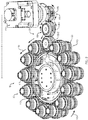
- Fig. 2 taken in combination with Fig. 1 , illustrates an example arrangement of the driving assembly 30.
- the driving assembly 30 is disposed in operative communication with the set of unscrewing assemblies 20 and at least a portion of the elevator assembly 40 and is configured to actuate the set of unscrewing assemblies 20 and at least a portion of the elevator assembly 40 during operation, as will be described below.
- the driving assembly 30 includes a driver element 106, a set of idler elements 108, and a driving element 112 which are rotatably coupled, in a single plane, to the mounting plate 104.
- the mounting plate 104 is configured to support, and to allow relative rotation of, each of the driver element 106, set of idler elements 108, and driving element 112 during operation.
- the driver element 106, set of idler elements 108, and the driving element 112 can be configured in a variety of ways, in one arrangement, the elements 108, 108, 112 are configured as gears such that the driver element 106 is configured to mesh with the set of idler elements 108, and the set of idler elements 108 are configured to mesh with the driving element 112.
- the driver element 106 is connected to a motor assembly 115, such as a servo motor and gearbox, and includes a set of peripheral teeth 107 which mesh with corresponding peripheral teeth 109 of the set of idler elements 108.
- the set of idler elements 108 are configured to dispose the motor assembly 115 and the associated driver element 106 at lateral distance d from the driving element 112 in order to minimize interference between the motor assembly 115 and the driving element 112 during operation. While the set of idler elements 108 can include any number of idler elements, in one arrangement, the set of idler elements 108 includes a first idler element 108-1 and a second idler element 108-2.
- Rotation of the driving element 112 is configured to actuate the unscrewing assemblies 20 and operate the elevator assembly 40 to disengage threaded molded articles from the corresponding threaded cores 130 following a molding procedure.
- the set of unscrewing assemblies 20 includes a plurality of individual unscrewing assemblies 110 are disposed about an outer circumference of the driving element 112.
- the set of unscrewing assemblies 20 includes twelve unscrewing assemblies 110 disposed about the circumference of the driving element 112 and in operative communication with the driving element 112.
- each unscrewing assembly 110 includes a base 123 and an unscrewing element 126.
- the base 123 is connected to the mounting plate 104 and the unscrewing element 126 is rotatably connected to the base 123.
- the unscrewing element 126 surrounds the threaded core 130 of an injection mold and is disposed in operative communication with the driving element 112.
- the unscrewing element 126 carries a set of teeth 122 disposed peripherally about a circumference of the unscrewing assembly 110 and bearing elements 124.
- the teeth 122 of the unscrewing element 126 are configured to mesh with a set of teeth 120 disposed peripherally about a circumference of the driving element 112.
- the unscrewing assembly 110 is configured to engage a portion threaded mold article to allow removal of the threaded mold article from the threaded core 130 following a molding procedure.
- the unscrewing element 126 includes a set of ratcheting teeth 128 configured to engage a portion of the threaded molded article, such as a base or bottom skirt of a threaded molded article.
- rotation of the driving element 112 rotates the unscrewing element 126 of each unscrewing assembly 110 to decouple or loosen a threaded molded article from a corresponding threaded core 130.
- rotation of the driver element 106 in a counterclockwise direction causes the driving element 112 to rotate in a clockwise direction 117 via idler elements 108-1, 108-2.
- Such rotation of the driving element 112 causes the unscrewing element 126 of each unscrewing assembly 110 to rotate in a counterclockwise direction 119.
- the ratcheting teeth 128 rotate the threaded molded article counterclockwise about a longitudinal axis 121 relative to threaded core 130. Rotation of the threaded molded article relative to the threaded core 130 disengages the threads of the threaded molded article from corresponding threads 132 of the threaded core 130.
- the driving assembly 30 is also configured to operate the elevator assembly 40 to disengage threaded molded articles from the corresponding threaded cores 130.
- the elevator assembly 40 includes a first elevator element 114, also termed a helical ramp cam follower, and a second elevator element 140, also termed a helical elevator cam follower.
- interaction between the first elevator element 114 and the second elevator element 140 is configured to cause translation of a threaded molded article from the threaded core 130 along a longitudinal direction 300.
- the first elevator element 114 includes a first or top portion 116 and a second or bottom portion 120 opposing the first portion 116.
- the top portion 116 of the first elevator element 114 is rotatably connected to the mounting plate 104 via driving element 112.
- the first portion 116 of the first elevator element 114 can be secured to a planar face of the driving element 112 such that the second portion 120 extends toward the fixed plate 200 of the ejection system 10.
- the first portion 116 of the first elevator element 114 can be secured to the driving element 112 such that the second portion 120 of the first elevator element 114 extends through an opening defined by the driving element 112 toward the fixed plate 200. Accordingly, with such connection, rotation of the driving element 112 in a clockwise direction 117 also causes the first elevator element 114 to rotate in a clockwise direction.
- the second portion 120 of the first elevator element 114 is configured to engage a first portion 144 of the second elevator element 140.
- the second portion 120 of the first elevator element 114 defines a substantially helically-shaped interface 129.
- the substantially helically-shaped interface 129 of the second portion 120 defines an angle of inclination 133 that increases about the circumference of first elevator element 114 from a first radial location 125 to a second radial location 127.
- a meeting location or interface between the first and second radial locations 125, 127 defines a vertical face 122 of the first elevator element 114.
- the second elevator element 140 includes the first or top portion 144 and a second or bottom portion 146 opposing the first portion 144.
- the second or bottom portion 146 of the second elevator element 140 is connected to the fixed plate 200. Accordingly, in use, rotation of the driving element 112 will not cause substantial motion or rotation of the second elevator element 140.
- the first portion 144 of the second elevator element 140 defines a substantially helically-shaped interface 142.
- the interface 142 of the first portion 144 defines an angle of inclination 149 that increases about the circumference of the second elevator element 140 from a first radial location 145 to a second radial location 147.
- a meeting location between the first and second radial locations 145, 147 defines a vertical face 148 of the second elevator element 140.
- the vertical face 122 of the first elevator element 114 abuts the vertical face 148 of the second elevator element 140. Accordingly, the substantially thickest portion 127 of the helically-shaped interface 129 of the first elevator element 114 opposes the substantially thinnest portion 145 of the helically-shaped interface 142 of the second elevator element 140. With such positioning, the mounting plate 104 and the fixed plate 200 are disposed in a closed or first position as illustrated in Fig. 1 .
- Rotation of the driving element 112 in a clockwise direction 117 causing the first elevator element 114 to rotate relative to the second elevator element 140 causes the helically-shaped interface 129 of the first elevator element 114 to rotate relative to the helically-shaped interface 142 of the second elevator element 140.
- Such rotation move the substantially thickest portion 127 of the interface 129 of the first elevator element 114 towards the substantially thickest portion 147 of the interface 142 of the second elevator element 140.
- This causes the mounting plate 104, including the unscrewing assembly 110, to translate along direction 300 relative to the fixed plate 200 between the first position, as indicated in Fig. 1 , and a second or open position, as indicated by the gap 302 between the mounting plate 104 and the fixed plate 200 in Fig. 10 .
- Linear translation of the unscrewing assemblies 110 provides linear translation of molded threaded articles relative to the threaded cores 130 of the injection mold 5.
- the first and second elevator elements 114, 140 are configured to provide substantially continuous cam action to the threaded mold decoupling system 15.
- the substantially continuous cam action provides a relatively faster cycle time relative to conventional mechanisms, as it is not necessary to reset the elevator elements 114, 140 during the cycle.
- use of the first and second elevator elements 114, 140 provides a relative increase in the speed at which the molded articles can be decoupled from the threaded cores 130 which, in turn, increases the relative quantity of threaded molded articles that an associated injection mold 5 can produce.
- each unscrewing assembly 110 With respect to the operation of the driving assembly 30, the rotation of the driving element 112 causes the unscrewing core 126 of each unscrewing assembly 110 to rotate in a counterclockwise direction to disengage threaded molded articles from their corresponding threaded cores 130. Further, rotation of the driving element 112 also causes linear translation 300 of each unscrewing assembly 110, including the translation of the unscrewing core 126 of each unscrewing assembly 110, relative to the threaded core 130. Accordingly, by providing substantially simultaneous rotational and linear motion to the unscrewing core 126 of each decoupling assembly 110, each unscrewing assembly 110 provides decoupling of a threaded molded article from a corresponding threaded core 130.
- an ejection mechanism such as a preloaded spring mechanism (e.g., a Bellville disc spring mechanism), can advance the stripper plate forward to eject the threaded molded articles from the corresponding threaded cores 130.
- the preloaded spring mechanism such as a Bellville disc spring mechanism, is configured to provide a preset clearance on a taper shutoff between the decoupling assemblies and the corresponding threaded core 130.
- an ejection mechanism such as a pneumatic ejection assist system can eject the molded plastic components from the injection mold 5.
- the driving assembly 30 is configured to rewind the first elevator element 114 and unscrewing assemblies 110 back to a starting position.
- rotation of the driver element 106 by the motor assembly in a clockwise direction causes the driving element 112 to rotate in a counterclockwise direction via idler elements 108-1, 108-2.
- Such rotation of the driving element 112 causes the unscrewing element 126 of each unscrewing assembly 110 to rotate in a clockwise direction to reset the ratcheting teeth 128 to a first or starting position.
- rotation of the driving element 112 in the counterclockwise direction causes the first elevator element 114 to rotate in a counterclockwise direction relative to the second elevator element 140.
- Such rotation translates the substantially thickest portion 127 of the interface 129 of the first elevator element 114 from a location in opposition with the substantially thickest portion 147 of the interface 142 of the second elevator element 140 to a location in opposition with the substantially thinnest portion 145 of the interface 142 of the second elevator element 140.
- the vertical face 122 of the first elevator element 114 abuts the vertical face 148 of the second elevator element 140.
- such relative positioning of the first and second elevator elements 114, 140 causes the mounting plate 104 to translate along direction 304 relative to the fixed plate 200 between the second position, as indicated in Fig. 10 , and a first position, as indicated in Fig. 1 .
- the set of unscrewing assemblies 20 includes a plurality of individual unscrewing assemblies 110 that are disposed about an outer circumference of the driving element 112.
- the set of unscrewing assemblies 20 includes twelve unscrewing assemblies 110 disposed about the circumference of the driving element 112 and in operative communication with the driving element 112.
- the driving element 112 is configured to rotate the unscrewing element 126 of each unscrewing assembly 110 to disengage a threaded molded article from a corresponding treaded core 130.
- Such an arrangement is by way of example only. In one arrangement, as illustrated in Fig.
- the set of unscrewing assemblies 20 defines subsets of unscrewing assemblies 350 where each subset of unscrewing assemblies includes a hub element 400 disposed in operative communication with the plurality of unscrewing assemblies and one unscrewing assembly 110 of the subset of unscrewing assemblies 350 being disposed in operative communication with a driving element 112.
- the first subset of unscrewing assemblies 350-1 includes first, second, third, and fourth unscrewing assemblies 110-1 through 110-4 disposed in operative communication with hub element 400-1.
- the hub element 400-1 can be a gear having teeth configured to mesh with the teeth 122 of each unscrewing assembly 110-1 through 110-4.
- the first subset of unscrewing assemblies 350-1 further includes an unscrewing assembly, in this case unscrewing assembly 110-1, disposed in operative communication with the driving element 112, such as via a meshing of the teeth 122 of the unscrewing assembly 110-1 with the teeth 120 of the driving element 112.
- the driving element 112 rotates clockwise via rotation of the driver element 106 and idler element 108
- the driving element 112 rotates the first unscrewing assembly 110-1 in a counterclockwise direction.
- Rotation of the first unscrewing assembly 110-1 in turn, rotates the hub element 400-1 in a clockwise direction.
- the hub element 400-1 transfers this rotational movement to the unscrewing element 126 of each of the second, third, and fourth unscrewing assemblies 110-2, 110-3, 110-4 to decouple or loosen a respective threaded molded article from a corresponding threaded core 130.
Landscapes
- Engineering & Computer Science (AREA)
- Mechanical Engineering (AREA)
- Manufacturing & Machinery (AREA)
- Moulds For Moulding Plastics Or The Like (AREA)
Claims (10)
- Gewindeform mit Trennsystem (15), umfassend:mindestens eine Ausschraubanordnung (110), die so konfiguriert ist, dass sie drehbar mit einer Montageplatte (104) gekoppelt werden kann, wobei die mindestens eine Ausschraubanordnung (110) in der Nähe eines Gewindekerns (130) einer Spritzgussform (5) angeordnet ist;eine Aufzugsanordnung (40) mit einem ersten Aufzugselement (114), das so konfiguriert ist, dass es drehbar mit der Montageplatte (104) gekoppelt werden kann, und einem zweiten Aufzugselement (140), das so konfiguriert ist, dass es mit einer festen Platte (200) verbunden werden kann, wobei die feste Platte (200) der Montageplatte (104) gegenüberliegt; undeine Antriebsanordnung (30), die in Wirkverbindung mit der mindestens einen Ausschraubanordnung (110) und mit dem ersten Aufzugselement (114) der Aufzugsanordnung (40) angeordnet ist, wobei die Antriebsanordnung (30) zu Folgendem konfiguriert ist:Betätigen der mindestens einen Ausschraubanordnung (110), um einen Formkörper um eine Längsachse des Gewindekerns (130) zu drehen, undBetätigen des ersten Aufzugselements (114) relativ zu dem zweiten Aufzugselement (140), um die Montageplatte (104) relativ zu der festen Platte (200) linear zu verschieben und den Formkörper entlang der Längsachse des Gewindekerns (130) zu verschieben.
- Gewindeform mit Trennsystem (15) nach Anspruch 1, wobei die Antriebsanordnung (30) ein Antriebselement (112) umfasst, das drehbar mit der Montageplatte (104) verbunden ist.
- Gewindeform mit Trennsystem (15) nach Anspruch 2, wobei die mindestens eine Ausschraubanordnung (110) umfasst:eine Basis (123), die mit der Montageplatte (104) verbunden ist; undein Ausschraubelement (126), das drehbar mit der Basis (123) verbunden ist, wobei das Ausschraubelement (126) in Wirkverbindung mit dem Antriebselement (112) angeordnet ist, um den Gewindekern (130) der Spritzgussform (5) herum angeordnet ist und so konfiguriert ist, dass es mit einem Abschnitt des Formkörpers in Eingriff kommt.
- Gewindeform mit Trennsystem (15) nach Anspruch 3, wobei die mindestens eine Ausschraubanordnung (110) eine Vielzahl von Ausschraubanordnungen (110) umfasst, wobei jede Ausschraubanordnung (110) der Vielzahl von Ausschraubanordnungen (110) um einen Außenumfang des Antriebselements (112) angeordnet ist und jede Ausschraubanordnung (110) der Vielzahl von Ausschraubanordnungen in Wirkverbindung mit dem Antriebselement (112) angeordnet ist.
- Gewindeform mit Trennsystem (15) nach Anspruch 3, wobei die mindestens eine Ausschraubanordnung (110) eine Vielzahl von Ausschraubanordnungen (110) und ein Nabenelement (400) umfasst, das in Wirkverbindung mit der Vielzahl von Ausschraubanordnungen (110) angeordnet ist, wobei eine Ausschraubanordnung (110) der Vielzahl von Ausschraubanordnungen (110) in Wirkverbindung mit dem Antriebselement (112) angeordnet ist.
- Gewindeform mit Trennsystem (15) nach Anspruch 2, wobei das erste Aufzugselement (114) mit dem Antriebselement (112) verbunden ist und über das Antriebselement (112) drehbar mit der Montageplatte (104) verbunden ist.
- Gewindeform mit Trennsystem (15) nach Anspruch 6, wobei das erste Aufzugselement (114) eine im Wesentlichen spiralförmige Schnittstelle (129) umfasst, die Folgendes definiert:einen Neigungswinkel (133), der um den Umfang des ersten Aufzugselements (114) von einer ersten radialen Stelle (125) zu einer zweiten radialen Stelle (127) zunimmt; undeine vertikale Fläche (122), die zwischen der ersten radialen Stelle (125) und der zweiten radialen Stelle (127) angeordnet ist.
- Gewindeform mit Trennsystem (15) nach Anspruch 7, wobei das zweite Aufzugselement (140) eine im Wesentlichen spiralförmige Schnittstelle (142) umfasst, die Folgendes definiert:einen Neigungswinkel (149), der um den Umfang des zweiten Aufzugselements (140) von einer ersten radialen Stelle (145) zu einer zweiten radialen Stelle (147) zunimmt; undeine vertikale Fläche (148), die zwischen der ersten radialen Stelle (145) und der zweiten radialen Stelle (147) angeordnet ist.
- Gewindeform mit Trennsystem (15) nach Anspruch 1, wobei das Antriebselement (112) so konfiguriert ist, dass es ein erstes Aufzugselement (114) relativ zu einem zweiten Aufzugselement (140) dreht, um die Montageplatte (104) zwischen einer ersten Position relativ zu der festen Platte (200) und einer zweiten Position relativ zu der festen Platte (200) anzuordnen.
- Auswurfsystem (10), umfassend:die feste Platte (200);die Montageplatte (104), die der festen Platte (200) gegenüberliegt und so konfiguriert ist, dass sie sich relativ zu der festen Platte (200) verschiebt; undeine Gewindeform mit Trennsystem (15) nach einem der Ansprüche 1 bis 9.
Applications Claiming Priority (2)
| Application Number | Priority Date | Filing Date | Title |
|---|---|---|---|
| US201562235956P | 2015-10-01 | 2015-10-01 | |
| PCT/US2016/054435 WO2017059065A1 (en) | 2015-10-01 | 2016-09-29 | Threaded mold decoupling system |
Publications (3)
| Publication Number | Publication Date |
|---|---|
| EP3356112A1 EP3356112A1 (de) | 2018-08-08 |
| EP3356112A4 EP3356112A4 (de) | 2018-10-31 |
| EP3356112B1 true EP3356112B1 (de) | 2020-11-11 |
Family
ID=58427837
Family Applications (1)
| Application Number | Title | Priority Date | Filing Date |
|---|---|---|---|
| EP16852591.3A Active EP3356112B1 (de) | 2015-10-01 | 2016-09-29 | Gewindeform mit trennsystem |
Country Status (3)
| Country | Link |
|---|---|
| US (2) | US10213945B2 (de) |
| EP (1) | EP3356112B1 (de) |
| WO (1) | WO2017059065A1 (de) |
Families Citing this family (4)
| Publication number | Priority date | Publication date | Assignee | Title |
|---|---|---|---|---|
| CN108000817B (zh) * | 2017-11-30 | 2019-07-30 | 重庆鑫际激光科技有限公司 | 旋转式零部件脱模模具 |
| CN110216847A (zh) * | 2018-03-04 | 2019-09-10 | 高勇勇 | 一种中央蜗杆驱动型齿轮脱螺纹机构 |
| CN110281372B (zh) * | 2019-07-08 | 2024-08-20 | 江苏信息职业技术学院 | 一种模具转运取模机构 |
| US20210060838A1 (en) * | 2019-09-03 | 2021-03-04 | Nypromold, Inc. | Threaded mold decoupling assembly |
Family Cites Families (10)
| Publication number | Priority date | Publication date | Assignee | Title |
|---|---|---|---|---|
| US5061168A (en) | 1990-07-09 | 1991-10-29 | Fox Alton L | Modular unscrewing mold apparatus |
| US5565223A (en) * | 1993-09-27 | 1996-10-15 | Husky Injection Molding Systems Ltd. | Apparatus for forming molded article |
| JP3312525B2 (ja) * | 1995-03-20 | 2002-08-12 | 三菱マテリアル株式会社 | 内ねじキャップの成形用金型装置 |
| US6241931B1 (en) * | 1998-06-01 | 2001-06-05 | Top Grade Machining Ltd. | Threaded lid injection mold release |
| US6238202B1 (en) * | 1999-02-26 | 2001-05-29 | Unique Mould Makers Limited | Apparatus for ejecting threaded injection molded parts |
| JP2001121588A (ja) * | 1999-10-27 | 2001-05-08 | Toshiba Mach Co Ltd | 射出成形機におけるエジェクター装置 |
| US6599115B2 (en) * | 2001-05-07 | 2003-07-29 | Precise Technology, Inc. | Mold unscrewing mechanism for making threaded articles |
| US7157037B2 (en) * | 2004-12-20 | 2007-01-02 | Creating Mold Solutions, Inc. | Apparatus for making threaded articles in a plastic injection molding process |
| SG195617A1 (en) * | 2009-11-30 | 2013-12-30 | Husky Injection Molding | Molding apparatus |
| DE102011010442B4 (de) * | 2011-02-04 | 2014-09-25 | Thomas Meister | Gewindekernausschraubvorrichtung |
-
2016
- 2016-09-29 EP EP16852591.3A patent/EP3356112B1/de active Active
- 2016-09-29 WO PCT/US2016/054435 patent/WO2017059065A1/en not_active Ceased
-
2018
- 2018-03-28 US US15/938,913 patent/US10213945B2/en active Active
-
2019
- 2019-02-19 US US16/279,729 patent/US10647041B2/en active Active
Non-Patent Citations (1)
| Title |
|---|
| None * |
Also Published As
| Publication number | Publication date |
|---|---|
| US20180215087A1 (en) | 2018-08-02 |
| WO2017059065A1 (en) | 2017-04-06 |
| US10647041B2 (en) | 2020-05-12 |
| US10213945B2 (en) | 2019-02-26 |
| EP3356112A4 (de) | 2018-10-31 |
| US20190176381A1 (en) | 2019-06-13 |
| EP3356112A1 (de) | 2018-08-08 |
Similar Documents
| Publication | Publication Date | Title |
|---|---|---|
| US10647041B2 (en) | Threaded mold decoupling system | |
| EP2930075B1 (de) | Aktuator für elektronische feststellbremse | |
| CA2194614C (en) | Apparatus for forming threaded moulded articles | |
| CN103921443A (zh) | 3d打印方法及3d打印系统 | |
| US10654205B2 (en) | Injection molding apparatus, method, and system | |
| JP5394335B2 (ja) | 射出成形機の中間型盤 | |
| US6156265A (en) | Powder compacting apparatus and method of forming helical gear wheel using said powder compacting apparatus | |
| CN103950143A (zh) | 多工位注塑成型模具 | |
| KR101010406B1 (ko) | 립스틱 용기의 리드링 사출용 금형장치 | |
| US10857712B2 (en) | Tandem mold for creating injection-molded parts from synthetic material | |
| CN111002533A (zh) | 保证带定位螺纹产品的螺纹起始点一致性的方法 | |
| CN106182647B (zh) | 设有单螺杆控制多腔脱螺纹机构的模具 | |
| RU2423232C2 (ru) | Машина для компрессионного формования крышек | |
| CN217169487U (zh) | 适用于内外双层螺牙脱模的模具 | |
| EP3789177A1 (de) | Anordnung zur entkopplung einer gewindeform | |
| JP2005329662A (ja) | ネジ抜き装置 | |
| CN216329743U (zh) | 一种模芯机构及带斜齿螺牙的产品注塑模具 | |
| JP2004050523A (ja) | 射出成形用金型 | |
| CN213108007U (zh) | 一种快速高效脱模的注塑模具 | |
| CN216423272U (zh) | 一种机械壳体零部件专用注塑模具 | |
| CN106113413B (zh) | 利用双层斜齿脱模机构成型的模具 | |
| CN108357058B (zh) | 一种具有弧面的注塑件自脱模模具 | |
| CN212666566U (zh) | 一种牙膏盖的注塑模具 | |
| CN106273284A (zh) | 一种带有螺旋叶片注塑件成型后顶出机构的模具 | |
| CN212219127U (zh) | 一种扇形螺旋齿轮轴芯机构 |
Legal Events
| Date | Code | Title | Description |
|---|---|---|---|
| STAA | Information on the status of an ep patent application or granted ep patent |
Free format text: STATUS: THE INTERNATIONAL PUBLICATION HAS BEEN MADE |
|
| PUAI | Public reference made under article 153(3) epc to a published international application that has entered the european phase |
Free format text: ORIGINAL CODE: 0009012 |
|
| STAA | Information on the status of an ep patent application or granted ep patent |
Free format text: STATUS: REQUEST FOR EXAMINATION WAS MADE |
|
| 17P | Request for examination filed |
Effective date: 20180329 |
|
| AK | Designated contracting states |
Kind code of ref document: A1 Designated state(s): AL AT BE BG CH CY CZ DE DK EE ES FI FR GB GR HR HU IE IS IT LI LT LU LV MC MK MT NL NO PL PT RO RS SE SI SK SM TR |
|
| AX | Request for extension of the european patent |
Extension state: BA ME |
|
| A4 | Supplementary search report drawn up and despatched |
Effective date: 20181001 |
|
| RIC1 | Information provided on ipc code assigned before grant |
Ipc: B29C 45/32 20060101ALI20180925BHEP Ipc: B29C 33/00 20060101ALI20180925BHEP Ipc: B29C 45/40 20060101ALI20180925BHEP Ipc: B29C 33/44 20060101ALI20180925BHEP Ipc: B29C 45/26 20060101AFI20180925BHEP Ipc: B29L 31/56 20060101ALI20180925BHEP Ipc: B29C 43/50 20060101ALI20180925BHEP |
|
| DAV | Request for validation of the european patent (deleted) | ||
| DAX | Request for extension of the european patent (deleted) | ||
| GRAP | Despatch of communication of intention to grant a patent |
Free format text: ORIGINAL CODE: EPIDOSNIGR1 |
|
| STAA | Information on the status of an ep patent application or granted ep patent |
Free format text: STATUS: GRANT OF PATENT IS INTENDED |
|
| INTG | Intention to grant announced |
Effective date: 20200609 |
|
| GRAS | Grant fee paid |
Free format text: ORIGINAL CODE: EPIDOSNIGR3 |
|
| GRAA | (expected) grant |
Free format text: ORIGINAL CODE: 0009210 |
|
| STAA | Information on the status of an ep patent application or granted ep patent |
Free format text: STATUS: THE PATENT HAS BEEN GRANTED |
|
| AK | Designated contracting states |
Kind code of ref document: B1 Designated state(s): AL AT BE BG CH CY CZ DE DK EE ES FI FR GB GR HR HU IE IS IT LI LT LU LV MC MK MT NL NO PL PT RO RS SE SI SK SM TR |
|
| REG | Reference to a national code |
Ref country code: GB Ref legal event code: FG4D |
|
| REG | Reference to a national code |
Ref country code: CH Ref legal event code: EP |
|
| REG | Reference to a national code |
Ref country code: AT Ref legal event code: REF Ref document number: 1333023 Country of ref document: AT Kind code of ref document: T Effective date: 20201115 |
|
| REG | Reference to a national code |
Ref country code: DE Ref legal event code: R096 Ref document number: 602016047843 Country of ref document: DE |
|
| REG | Reference to a national code |
Ref country code: IE Ref legal event code: FG4D |
|
| REG | Reference to a national code |
Ref country code: NL Ref legal event code: MP Effective date: 20201111 |
|
| REG | Reference to a national code |
Ref country code: AT Ref legal event code: MK05 Ref document number: 1333023 Country of ref document: AT Kind code of ref document: T Effective date: 20201111 |
|
| PG25 | Lapsed in a contracting state [announced via postgrant information from national office to epo] |
Ref country code: RS Free format text: LAPSE BECAUSE OF FAILURE TO SUBMIT A TRANSLATION OF THE DESCRIPTION OR TO PAY THE FEE WITHIN THE PRESCRIBED TIME-LIMIT Effective date: 20201111 Ref country code: PT Free format text: LAPSE BECAUSE OF FAILURE TO SUBMIT A TRANSLATION OF THE DESCRIPTION OR TO PAY THE FEE WITHIN THE PRESCRIBED TIME-LIMIT Effective date: 20210311 Ref country code: NO Free format text: LAPSE BECAUSE OF FAILURE TO SUBMIT A TRANSLATION OF THE DESCRIPTION OR TO PAY THE FEE WITHIN THE PRESCRIBED TIME-LIMIT Effective date: 20210211 Ref country code: GR Free format text: LAPSE BECAUSE OF FAILURE TO SUBMIT A TRANSLATION OF THE DESCRIPTION OR TO PAY THE FEE WITHIN THE PRESCRIBED TIME-LIMIT Effective date: 20210212 Ref country code: FI Free format text: LAPSE BECAUSE OF FAILURE TO SUBMIT A TRANSLATION OF THE DESCRIPTION OR TO PAY THE FEE WITHIN THE PRESCRIBED TIME-LIMIT Effective date: 20201111 |
|
| PG25 | Lapsed in a contracting state [announced via postgrant information from national office to epo] |
Ref country code: AT Free format text: LAPSE BECAUSE OF FAILURE TO SUBMIT A TRANSLATION OF THE DESCRIPTION OR TO PAY THE FEE WITHIN THE PRESCRIBED TIME-LIMIT Effective date: 20201111 Ref country code: BG Free format text: LAPSE BECAUSE OF FAILURE TO SUBMIT A TRANSLATION OF THE DESCRIPTION OR TO PAY THE FEE WITHIN THE PRESCRIBED TIME-LIMIT Effective date: 20210211 Ref country code: IS Free format text: LAPSE BECAUSE OF FAILURE TO SUBMIT A TRANSLATION OF THE DESCRIPTION OR TO PAY THE FEE WITHIN THE PRESCRIBED TIME-LIMIT Effective date: 20210311 Ref country code: PL Free format text: LAPSE BECAUSE OF FAILURE TO SUBMIT A TRANSLATION OF THE DESCRIPTION OR TO PAY THE FEE WITHIN THE PRESCRIBED TIME-LIMIT Effective date: 20201111 Ref country code: LV Free format text: LAPSE BECAUSE OF FAILURE TO SUBMIT A TRANSLATION OF THE DESCRIPTION OR TO PAY THE FEE WITHIN THE PRESCRIBED TIME-LIMIT Effective date: 20201111 Ref country code: SE Free format text: LAPSE BECAUSE OF FAILURE TO SUBMIT A TRANSLATION OF THE DESCRIPTION OR TO PAY THE FEE WITHIN THE PRESCRIBED TIME-LIMIT Effective date: 20201111 |
|
| REG | Reference to a national code |
Ref country code: LT Ref legal event code: MG9D |
|
| PG25 | Lapsed in a contracting state [announced via postgrant information from national office to epo] |
Ref country code: HR Free format text: LAPSE BECAUSE OF FAILURE TO SUBMIT A TRANSLATION OF THE DESCRIPTION OR TO PAY THE FEE WITHIN THE PRESCRIBED TIME-LIMIT Effective date: 20201111 |
|
| PG25 | Lapsed in a contracting state [announced via postgrant information from national office to epo] |
Ref country code: SK Free format text: LAPSE BECAUSE OF FAILURE TO SUBMIT A TRANSLATION OF THE DESCRIPTION OR TO PAY THE FEE WITHIN THE PRESCRIBED TIME-LIMIT Effective date: 20201111 Ref country code: RO Free format text: LAPSE BECAUSE OF FAILURE TO SUBMIT A TRANSLATION OF THE DESCRIPTION OR TO PAY THE FEE WITHIN THE PRESCRIBED TIME-LIMIT Effective date: 20201111 Ref country code: CZ Free format text: LAPSE BECAUSE OF FAILURE TO SUBMIT A TRANSLATION OF THE DESCRIPTION OR TO PAY THE FEE WITHIN THE PRESCRIBED TIME-LIMIT Effective date: 20201111 Ref country code: EE Free format text: LAPSE BECAUSE OF FAILURE TO SUBMIT A TRANSLATION OF THE DESCRIPTION OR TO PAY THE FEE WITHIN THE PRESCRIBED TIME-LIMIT Effective date: 20201111 Ref country code: LT Free format text: LAPSE BECAUSE OF FAILURE TO SUBMIT A TRANSLATION OF THE DESCRIPTION OR TO PAY THE FEE WITHIN THE PRESCRIBED TIME-LIMIT Effective date: 20201111 Ref country code: SM Free format text: LAPSE BECAUSE OF FAILURE TO SUBMIT A TRANSLATION OF THE DESCRIPTION OR TO PAY THE FEE WITHIN THE PRESCRIBED TIME-LIMIT Effective date: 20201111 |
|
| REG | Reference to a national code |
Ref country code: DE Ref legal event code: R097 Ref document number: 602016047843 Country of ref document: DE |
|
| PG25 | Lapsed in a contracting state [announced via postgrant information from national office to epo] |
Ref country code: DK Free format text: LAPSE BECAUSE OF FAILURE TO SUBMIT A TRANSLATION OF THE DESCRIPTION OR TO PAY THE FEE WITHIN THE PRESCRIBED TIME-LIMIT Effective date: 20201111 |
|
| PLBE | No opposition filed within time limit |
Free format text: ORIGINAL CODE: 0009261 |
|
| STAA | Information on the status of an ep patent application or granted ep patent |
Free format text: STATUS: NO OPPOSITION FILED WITHIN TIME LIMIT |
|
| 26N | No opposition filed |
Effective date: 20210812 |
|
| PG25 | Lapsed in a contracting state [announced via postgrant information from national office to epo] |
Ref country code: IT Free format text: LAPSE BECAUSE OF FAILURE TO SUBMIT A TRANSLATION OF THE DESCRIPTION OR TO PAY THE FEE WITHIN THE PRESCRIBED TIME-LIMIT Effective date: 20201111 Ref country code: AL Free format text: LAPSE BECAUSE OF FAILURE TO SUBMIT A TRANSLATION OF THE DESCRIPTION OR TO PAY THE FEE WITHIN THE PRESCRIBED TIME-LIMIT Effective date: 20201111 Ref country code: NL Free format text: LAPSE BECAUSE OF FAILURE TO SUBMIT A TRANSLATION OF THE DESCRIPTION OR TO PAY THE FEE WITHIN THE PRESCRIBED TIME-LIMIT Effective date: 20201111 |
|
| PG25 | Lapsed in a contracting state [announced via postgrant information from national office to epo] |
Ref country code: SI Free format text: LAPSE BECAUSE OF FAILURE TO SUBMIT A TRANSLATION OF THE DESCRIPTION OR TO PAY THE FEE WITHIN THE PRESCRIBED TIME-LIMIT Effective date: 20201111 |
|
| PG25 | Lapsed in a contracting state [announced via postgrant information from national office to epo] |
Ref country code: ES Free format text: LAPSE BECAUSE OF FAILURE TO SUBMIT A TRANSLATION OF THE DESCRIPTION OR TO PAY THE FEE WITHIN THE PRESCRIBED TIME-LIMIT Effective date: 20201111 |
|
| REG | Reference to a national code |
Ref country code: CH Ref legal event code: PL |
|
| REG | Reference to a national code |
Ref country code: BE Ref legal event code: MM Effective date: 20210930 |
|
| GBPC | Gb: european patent ceased through non-payment of renewal fee |
Effective date: 20210929 |
|
| PG25 | Lapsed in a contracting state [announced via postgrant information from national office to epo] |
Ref country code: IS Free format text: LAPSE BECAUSE OF FAILURE TO SUBMIT A TRANSLATION OF THE DESCRIPTION OR TO PAY THE FEE WITHIN THE PRESCRIBED TIME-LIMIT Effective date: 20210311 Ref country code: MC Free format text: LAPSE BECAUSE OF FAILURE TO SUBMIT A TRANSLATION OF THE DESCRIPTION OR TO PAY THE FEE WITHIN THE PRESCRIBED TIME-LIMIT Effective date: 20201111 |
|
| PG25 | Lapsed in a contracting state [announced via postgrant information from national office to epo] |
Ref country code: LU Free format text: LAPSE BECAUSE OF NON-PAYMENT OF DUE FEES Effective date: 20210929 Ref country code: IE Free format text: LAPSE BECAUSE OF NON-PAYMENT OF DUE FEES Effective date: 20210929 Ref country code: GB Free format text: LAPSE BECAUSE OF NON-PAYMENT OF DUE FEES Effective date: 20210929 Ref country code: FR Free format text: LAPSE BECAUSE OF NON-PAYMENT OF DUE FEES Effective date: 20210930 Ref country code: BE Free format text: LAPSE BECAUSE OF NON-PAYMENT OF DUE FEES Effective date: 20210930 |
|
| PG25 | Lapsed in a contracting state [announced via postgrant information from national office to epo] |
Ref country code: LI Free format text: LAPSE BECAUSE OF NON-PAYMENT OF DUE FEES Effective date: 20210930 Ref country code: CH Free format text: LAPSE BECAUSE OF NON-PAYMENT OF DUE FEES Effective date: 20210930 |
|
| PG25 | Lapsed in a contracting state [announced via postgrant information from national office to epo] |
Ref country code: CY Free format text: LAPSE BECAUSE OF FAILURE TO SUBMIT A TRANSLATION OF THE DESCRIPTION OR TO PAY THE FEE WITHIN THE PRESCRIBED TIME-LIMIT Effective date: 20201111 |
|
| P01 | Opt-out of the competence of the unified patent court (upc) registered |
Effective date: 20230525 |
|
| PG25 | Lapsed in a contracting state [announced via postgrant information from national office to epo] |
Ref country code: HU Free format text: LAPSE BECAUSE OF FAILURE TO SUBMIT A TRANSLATION OF THE DESCRIPTION OR TO PAY THE FEE WITHIN THE PRESCRIBED TIME-LIMIT; INVALID AB INITIO Effective date: 20160929 |
|
| PG25 | Lapsed in a contracting state [announced via postgrant information from national office to epo] |
Ref country code: MK Free format text: LAPSE BECAUSE OF FAILURE TO SUBMIT A TRANSLATION OF THE DESCRIPTION OR TO PAY THE FEE WITHIN THE PRESCRIBED TIME-LIMIT Effective date: 20201111 |
|
| PG25 | Lapsed in a contracting state [announced via postgrant information from national office to epo] |
Ref country code: TR Free format text: LAPSE BECAUSE OF FAILURE TO SUBMIT A TRANSLATION OF THE DESCRIPTION OR TO PAY THE FEE WITHIN THE PRESCRIBED TIME-LIMIT Effective date: 20201111 |
|
| PG25 | Lapsed in a contracting state [announced via postgrant information from national office to epo] |
Ref country code: MT Free format text: LAPSE BECAUSE OF FAILURE TO SUBMIT A TRANSLATION OF THE DESCRIPTION OR TO PAY THE FEE WITHIN THE PRESCRIBED TIME-LIMIT Effective date: 20201111 |
|
| PGFP | Annual fee paid to national office [announced via postgrant information from national office to epo] |
Ref country code: DE Payment date: 20250919 Year of fee payment: 10 |