EP3356152B1 - Support d'impression de sécurité et son procédé de fabrication - Google Patents
Support d'impression de sécurité et son procédé de fabrication Download PDFInfo
- Publication number
- EP3356152B1 EP3356152B1 EP16777744.0A EP16777744A EP3356152B1 EP 3356152 B1 EP3356152 B1 EP 3356152B1 EP 16777744 A EP16777744 A EP 16777744A EP 3356152 B1 EP3356152 B1 EP 3356152B1
- Authority
- EP
- European Patent Office
- Prior art keywords
- image
- sub
- tonal
- opacifying layers
- images
- Prior art date
- Legal status (The legal status is an assumption and is not a legal conclusion. Google has not performed a legal analysis and makes no representation as to the accuracy of the status listed.)
- Active
Links
Images





Classifications
-
- B—PERFORMING OPERATIONS; TRANSPORTING
- B42—BOOKBINDING; ALBUMS; FILES; SPECIAL PRINTED MATTER
- B42D—BOOKS; BOOK COVERS; LOOSE LEAVES; PRINTED MATTER CHARACTERISED BY IDENTIFICATION OR SECURITY FEATURES; PRINTED MATTER OF SPECIAL FORMAT OR STYLE NOT OTHERWISE PROVIDED FOR; DEVICES FOR USE THEREWITH AND NOT OTHERWISE PROVIDED FOR; MOVABLE-STRIP WRITING OR READING APPARATUS
- B42D25/00—Information-bearing cards or sheet-like structures characterised by identification or security features; Manufacture thereof
- B42D25/30—Identification or security features, e.g. for preventing forgery
- B42D25/351—Translucent or partly translucent parts, e.g. windows
-
- B—PERFORMING OPERATIONS; TRANSPORTING
- B42—BOOKBINDING; ALBUMS; FILES; SPECIAL PRINTED MATTER
- B42D—BOOKS; BOOK COVERS; LOOSE LEAVES; PRINTED MATTER CHARACTERISED BY IDENTIFICATION OR SECURITY FEATURES; PRINTED MATTER OF SPECIAL FORMAT OR STYLE NOT OTHERWISE PROVIDED FOR; DEVICES FOR USE THEREWITH AND NOT OTHERWISE PROVIDED FOR; MOVABLE-STRIP WRITING OR READING APPARATUS
- B42D25/00—Information-bearing cards or sheet-like structures characterised by identification or security features; Manufacture thereof
- B42D25/20—Information-bearing cards or sheet-like structures characterised by identification or security features; Manufacture thereof characterised by a particular use or purpose
- B42D25/23—Identity cards
-
- B—PERFORMING OPERATIONS; TRANSPORTING
- B42—BOOKBINDING; ALBUMS; FILES; SPECIAL PRINTED MATTER
- B42D—BOOKS; BOOK COVERS; LOOSE LEAVES; PRINTED MATTER CHARACTERISED BY IDENTIFICATION OR SECURITY FEATURES; PRINTED MATTER OF SPECIAL FORMAT OR STYLE NOT OTHERWISE PROVIDED FOR; DEVICES FOR USE THEREWITH AND NOT OTHERWISE PROVIDED FOR; MOVABLE-STRIP WRITING OR READING APPARATUS
- B42D25/00—Information-bearing cards or sheet-like structures characterised by identification or security features; Manufacture thereof
- B42D25/20—Information-bearing cards or sheet-like structures characterised by identification or security features; Manufacture thereof characterised by a particular use or purpose
- B42D25/21—Information-bearing cards or sheet-like structures characterised by identification or security features; Manufacture thereof characterised by a particular use or purpose for multiple purposes
-
- B—PERFORMING OPERATIONS; TRANSPORTING
- B42—BOOKBINDING; ALBUMS; FILES; SPECIAL PRINTED MATTER
- B42D—BOOKS; BOOK COVERS; LOOSE LEAVES; PRINTED MATTER CHARACTERISED BY IDENTIFICATION OR SECURITY FEATURES; PRINTED MATTER OF SPECIAL FORMAT OR STYLE NOT OTHERWISE PROVIDED FOR; DEVICES FOR USE THEREWITH AND NOT OTHERWISE PROVIDED FOR; MOVABLE-STRIP WRITING OR READING APPARATUS
- B42D25/00—Information-bearing cards or sheet-like structures characterised by identification or security features; Manufacture thereof
- B42D25/20—Information-bearing cards or sheet-like structures characterised by identification or security features; Manufacture thereof characterised by a particular use or purpose
- B42D25/24—Passports
-
- B—PERFORMING OPERATIONS; TRANSPORTING
- B42—BOOKBINDING; ALBUMS; FILES; SPECIAL PRINTED MATTER
- B42D—BOOKS; BOOK COVERS; LOOSE LEAVES; PRINTED MATTER CHARACTERISED BY IDENTIFICATION OR SECURITY FEATURES; PRINTED MATTER OF SPECIAL FORMAT OR STYLE NOT OTHERWISE PROVIDED FOR; DEVICES FOR USE THEREWITH AND NOT OTHERWISE PROVIDED FOR; MOVABLE-STRIP WRITING OR READING APPARATUS
- B42D25/00—Information-bearing cards or sheet-like structures characterised by identification or security features; Manufacture thereof
- B42D25/20—Information-bearing cards or sheet-like structures characterised by identification or security features; Manufacture thereof characterised by a particular use or purpose
- B42D25/29—Securities; Bank notes
-
- B—PERFORMING OPERATIONS; TRANSPORTING
- B42—BOOKBINDING; ALBUMS; FILES; SPECIAL PRINTED MATTER
- B42D—BOOKS; BOOK COVERS; LOOSE LEAVES; PRINTED MATTER CHARACTERISED BY IDENTIFICATION OR SECURITY FEATURES; PRINTED MATTER OF SPECIAL FORMAT OR STYLE NOT OTHERWISE PROVIDED FOR; DEVICES FOR USE THEREWITH AND NOT OTHERWISE PROVIDED FOR; MOVABLE-STRIP WRITING OR READING APPARATUS
- B42D25/00—Information-bearing cards or sheet-like structures characterised by identification or security features; Manufacture thereof
- B42D25/30—Identification or security features, e.g. for preventing forgery
- B42D25/36—Identification or security features, e.g. for preventing forgery comprising special materials
- B42D25/373—Metallic materials
-
- B—PERFORMING OPERATIONS; TRANSPORTING
- B42—BOOKBINDING; ALBUMS; FILES; SPECIAL PRINTED MATTER
- B42D—BOOKS; BOOK COVERS; LOOSE LEAVES; PRINTED MATTER CHARACTERISED BY IDENTIFICATION OR SECURITY FEATURES; PRINTED MATTER OF SPECIAL FORMAT OR STYLE NOT OTHERWISE PROVIDED FOR; DEVICES FOR USE THEREWITH AND NOT OTHERWISE PROVIDED FOR; MOVABLE-STRIP WRITING OR READING APPARATUS
- B42D25/00—Information-bearing cards or sheet-like structures characterised by identification or security features; Manufacture thereof
- B42D25/30—Identification or security features, e.g. for preventing forgery
- B42D25/36—Identification or security features, e.g. for preventing forgery comprising special materials
- B42D25/378—Special inks
-
- B—PERFORMING OPERATIONS; TRANSPORTING
- B42—BOOKBINDING; ALBUMS; FILES; SPECIAL PRINTED MATTER
- B42D—BOOKS; BOOK COVERS; LOOSE LEAVES; PRINTED MATTER CHARACTERISED BY IDENTIFICATION OR SECURITY FEATURES; PRINTED MATTER OF SPECIAL FORMAT OR STYLE NOT OTHERWISE PROVIDED FOR; DEVICES FOR USE THEREWITH AND NOT OTHERWISE PROVIDED FOR; MOVABLE-STRIP WRITING OR READING APPARATUS
- B42D25/00—Information-bearing cards or sheet-like structures characterised by identification or security features; Manufacture thereof
- B42D25/40—Manufacture
- B42D25/45—Associating two or more layers
Definitions
- the present invention relates to security print media suitable for use in making security documents such as banknotes, identity documents, passports, certificates and the like, as well as methods for manufacturing such security print media, and security documents made from the security print media.
- security documents are typically provided with one or more security elements which are difficult or impossible to replicate accurately with commonly available means, particularly photocopiers, scanners or commercial printers.
- Some types of security element are formed on the surface of a document substrate, for example by printing onto and/or embossing into a substrate such as to create fine-line patterns or latent images revealed upon tilting, whilst others including diffractive optical elements and the like are typically formed on an article such as a security thread or a transfer foil, which is then applied to or incorporated into the document substrate.
- a still further category of security element is that in which the security element is integrally formed in the document substrate itself.
- a well-known example of such a feature is the conventional watermark, formed in paper document substrates by controlling the papermaking process to as to vary the density of the paper fibres as they are laid down in accordance with a desired image.
- Techniques have been developed which can achieve highly intricate, multi-tonal watermarks which become visible when the substrate is viewed in transmitted light.
- Security elements such as watermarks which are integral to the document substrate have the significant benefit that they cannot be detached from the security document without destroying the integrity of the document.
- Polymer document substrates comprising typically a transparent or translucent polymer substrate with at least one opacifying layer coated on each side to receive print, have a number of benefits over conventional paper document substrates including increased lifetime due to their more robust nature and resistance to soiling. Polymer document substrates also lend themselves well to certain types of security features such as transparent windows which are more difficult to incorporate in paper-based documents. However, due to the non-fibrous construction of polymer substrates, conventional watermarking techniques are not available and as such the potential for forming security elements integrally in the substrate itself is limited. Instead, for polymer security documents, security elements are typically applied after the document substrate has been manufactured, for example as part of a subsequent security printing process line, or by the application of a foil.
- GB-A-2076337 discloses an identification card constructed of several film layers provided with a printed image which may consist of partially overlapping printed layers placed over each other.
- WO-A-2010/130755 discloses a security paper having an optically variable security element and an ink-receiving layer arranged over both, the ink-receiving layer being thinner in the area of the optically variable element such that it remains visible.
- a polymer document substrate - i.e. a security print medium, which can then be printed upon and otherwise processed into a security document - with an integral security feature, to enhance the security of the document substrate itself, and ultimately of security documents formed from it.
- a security print medium for forming security documents therefrom is defined in claim 1.
- the present invention also provides a method of making a security print medium as defined in claim 11.
- the primary function of the opacifying layers is to render the majority of the document non-transparent and to provide a suitable background on which to print graphics, security patterns and other information as may be required on the finished security document.
- a plurality of the opacifying layers additionally provide a security feature in the form of a multi-tone image which is visible at least when the media is viewed in transmitted light (and, in some embodiments, also when viewed in reflected light).
- the multi-tone image formed by the opacifying layers has a monochromatic "greyscale” appearance defined by relatively bright and relatively dark areas (and optionally one or more intermediate tones).
- greyscale a monochromatic "greyscale” appearance defined by relatively bright and relatively dark areas (and optionally one or more intermediate tones).
- additional layers can be provided to achieve a multi-coloured appearance.
- the opacifying layers need not be in direct contact with the surface of the polymer substrate. Rather, one or more additional (transparent or translucent) layers could be present between the polymer substrate and the opacifying layers, such as a primer layer and/or the additional coloured layer(s) mentioned above, the opacifying layers still being considered disposed "on" the substrate surface.
- the multi-tone image is achieved by inserting one or more gaps in each of a plurality of the opacifying layers (which otherwise cover substantially all of the polymer substrate, that is, preferably at least 50% of the substrate, more preferably at least 80% and most preferably all of the remaining substrate).
- the gap(s) are arranged according to a different respective sub-image, the cumulative effect of which is a variation in the optical density of the security print media across the region of the substrate, depending on the number of opacifying layers present at each point, resulting in the displayed multi-tone image. Locations in which fewer of the opacifying layers are present (i.e.
- the resulting multi-tone image can provide a strong three-dimensional effect, especially where the sub-images are arranged to achieve a gradual change in optical density across the image (on a scale when viewed by the naked eye).
- opacifying layers may be present which do not contribute to the multi-tone image, e.g. being entirely absent across the relevant region of the substrate or being provided uniformly across the region of the substrate.
- opacifying layer having gaps disposed in accordance with the same sub-image (provided there are at least two opacifying layers each having gaps disposed in accordance with different sub-images).
- the sub-images will either all be negative image versions of the multi-tone image, or all positive image versions of the multi-tone image, and not a mixture of both.
- a "negative image version" of an image is one in which elements of the image are defined by the absence of colour (in this case, the absence of the opacifying material) against a surrounding background of colour (i.e. the presence of the opacifying material), whereas a "positive image version” of an image is the reverse: elements of the image are defined by the presence of colour (i.e. the opacifying material) against empty surroundings (i.e. the absence of the opacifying material).
- a sub-image is a "negative image version" of the multi-tonal image does not mean that it is the reverse of the multi-tonal image. Rather, if the multi-tonal image is a negative image then typically each of the sub-images will also be negative image versions of the same image, and if the multi-tonal image is a positive image then typically each of the sub-images will be positive image versions of that image.
- each sub-image will each be "versions" of the multi-tone image in the sense that each will contribute to the definition of the same image, but any one of the sub-images by itself need not display all the elements which will be visible in the final multi-tone image. Rather, each portion of the multi-tone image will have a desired tone (or, analogously, optical density) relative to other portions of the multi-tone image and each portion will be present (i.e. correspond to an area of opacifying material) or absent (i.e. correspond to a gap) in each sub-image in dependence on the desired tone of that portion. Hence, each sub-image shows selected portions of the multi-tone image depending on their desired tone.
- each element of the multi-tone image is built up by the presence or absence of each opacifying layer in the portion corresponding to the image element, the tone of the element resulting from the number of opacifying layers present.
- All of the sub-images are aligned with one another so that each portion of the multi-tone image has the same location in each sub-image.
- each sub-image defines portions of the multi-tonal image which have a (desired) tonal value falling within a respective tonal value range, the size of each respective tonal value range being different. That is, each sub-image is based on a different respective tonal value range.
- the tonal value of each point of the multi-tone image can be defined on an arbitrary scale relative to the darkest tone and lightest tone present in the multi-tone image (e.g. corresponding to tonal values of 100% and 0% respectively), or on an absolute scale as may be measured for example using a transmission densitometer such as the MacBeth TD932 (e.g. darkest tone portions having an optical density of 0.9, and lightest tone portions having an optical density of 0).
- the size of the different tonal value ranges may increase in constant steps, e.g. by 10% or by 20% where the scale is relative, or by 0.1 or 0.2 where the scale is absolute) from one sub-image to another.
- the sub-images do not need to be physically arranged on or applied to the substrate in the same order as that denoted by their respective tonal value ranges.
- the order in which the opacifying layers (and their respective sub-images) are arranged on the substrate - and to which side(s) of the substrate each is applied - is generally unimportant since it is the cumulative effect of the layers which produces the desired image.
- each tonal value range falls within the tonal value range next in the sequence.
- a first sub-image may define portions of the multi-tone image having a tonal value in the range 0% to 10%
- a second sub-image may define portions having a tonal value in the range 0% to 20% (thereby including all the same portions as in the first sub-image, plus more)
- a third sub-image may define portions having a tonal value in the range 0% to 30%, and so on.
- the desired tone of each image portion will be provided by the cumulative effect of the sub-layers which define that portion.
- tonal value ranges share substantially the same first end value and differ in their second end values, but this is not essential.
- each or at least one of the sub-images will be a binary or "flat" image with no tonal variation: the opacifying material is either present or absent on a scale visible to the naked eye, with no intermediate areas.
- the sub-images are multi-tonal sub-images, preferably half-tone sub-images. In this way, multiple tones can be introduced within the sub-image itself, e.g.
- each individual opacifying layer may have an optical density in the range 0.1 to 0.5, more preferably 0.1 to 0.4, most preferably 0.1 to 0.3 (as measured on a transmission densitometer, with an aperture area equivalent to that of a circle with a 1mm diameter - a suitable transmission densitometer is the MacBeth TD932).
- the individual opacifying layers may or may not be of the same composition as one another - for example, in some preferred cases at least one of the opacifying layers will contain electrically conductive particles (desirable to reduce the effects of static charge), whereas others will not - but nonetheless, preferably, all of the opacifying layers are substantially the same colour as one another, most preferably a light and bright colour such as white (including off-white) or grey.
- the opacifying layers each have a brightness L* in CIE L*a*b* colour space of at least 70, preferably at least 80 and more preferably at least 90.
- the security print medium further comprises a mono-tone or multi-tone print of at least part of the multi-tonal image in one or multiple colours which contrast visually with the opacifying layers, located between at least one, preferably all, of the opacifying layers and the polymer substrate on the first and/or second surfaces thereof, the print of the multi-tonal image being in alignment with the sub-images in the opacifying layers.
- the print is most preferably located on the surface of the polymer substrate (optionally on top of an additional layer such as a primer), underneath all the opacifying layers, although it is also possible to locate it between any two of the opacifying layers.
- the term "print” is intended to cover an image formed of a composition such as ink applied by any technique including conventional printing methods such as gravure, flexographic printing, lithography etc., but also ablation methods in which an all-over ink layer is applied and then selectively removed to leave an image, e.g. using a laser.
- this print of the image could be a negative image version or a positive image version of the multi-tone image, irrespective of the nature of the sub-images. Indeed, it is preferred that if the sub-images are negative image versions, the print is a positive image version (so as to "colour in” the gaps in the opacifying layers), and vice versa.
- the print could be a flat, binary image.
- the print is itself a multi-tone print and comprises at least one multi-tone, preferably half-tone, print working. This can be used for example to add additional shading, e.g. using various different spatial densities of a dark-coloured ink such as black, to further enhance the multi-tonal nature of the overall image.
- the print is multi-coloured and may comprise at least two print workings in different colours.
- the end result is a multi-coloured, multi-tonal image of which the different colours are provided by the print whilst the shading is provided primarily by the opacifying layers (and optionally the print).
- the multi-tone image can be designed for intended viewing in either reflected or transmitted light (although, irrespective of the designed intention it will still be visible in at least transmitted light and in some cases both).
- the sub-images are configured such that a greater number of the opacifying layers overlap one another at locations across the substrate corresponding to darker tones in the multi-tone image, relative to the number of opacifying layers which overlap one another at locations corresponding to lighter tones in the multi-tone image, the multi-tone image being configured for viewing in transmitted light. If the same image is viewed in reflected light against a dark background, the multi-tone image may still be visible but will appear reversed, with those regions intended to be darkest appearing lightest and vice-versa.
- the sub-images are configured such that a smaller number of the opacifying layers overlap one another at locations across the substrate corresponding to darker tones in the multi-tone image, relative to the number of opacifying layers which overlap one another at locations corresponding to lighter tones in the multi-tone image, the multi-tone image being configured for viewing in reflected light.
- it is a dark background apparent through the opacifying layers which provides the darkness to the image, areas with more opacifying layers obscuring the dark background and reflecting light so as to appear brighter than areas with fewer opacifying layers. If the same image is viewed in transmitted light, the multi-tone image will still be visible but again will appear reversed as compared with the intended image.
- the multi-tonal image comprises an image of a three-dimensional object, preferably a geometrical solid or wireframe model, a person, an animal, a building or other architectural structure or a three-dimensional logo. Shadows in the image can be denoted by darker tones created by the multiple opacifying layers, and highlights by lighter tones.
- the plurality of overlapping opacifying layers includes at least three overlapping opacifying layers each having gap(s) defined in accordance with a different respective sub-image, preferably at least four, more preferably at least six.
- the thickness of each layer may be reduced to avoid an overly thick document substrate.
- All of the opacifying layers could be located on the same surface of the polymer substrate. However it is generally preferred to distribute the opacifying layers on both surfaces so that both sides of the document can later be printed on. Hence, advantageously, at least one of the plurality of overlapping opacifying layers is provided on each of the first and the second surfaces of the polymer substrate, preferably half of the plurality of overlapping opacifying layers being provided on each of the first and second surfaces. It should be noted that the opacifying layers do not need to be applied to the substrate in any particular order related to their sub-images although this may be preferred in some cases.
- the substrate can also be located at any position within, or on one side of, the set of layers as its location will not affect the end image displayed by the cumulative effect of the layers. Nonetheless for other reasons it may be desirable to provide at least one opacyifying layer on each surface of the substrate, e.g. to enable layer printing thereon and/or to protect the substrate or control its surface texture.
- the security print medium could additionally include one or more opacifying layers which do not take part in the formation of the multi-tone image.
- the security print medium further comprises one or more additional opacifying layers each comprising a layer of semi-opaque material disposed over substantially the whole area of the polymer substrate, the one or more additional opacifying layers each either extending continuously across the region of the substrate containing the multi-tonal image or comprising a gap substantially across the region.
- the security print medium could be configured such that at least one opacifying layer is present at every point across the region, so that the document substrate does not appear transparent.
- at least one transparent window region is formed by aligned gaps in each of the opacifying layers, the at least one transparent window region preferably substantially surrounding the multi-tonal image.
- the or each opacifying layer may be laid down via an application technique which results in no additional visible sub-structure to the layer beyond that defined by the sub-image, i.e. the opacifying material being present in a macroscopically uniform, homogenous layer across all regions outside the gaps defined by the sub-image. This will typically be the case where the layer is applied by gravure printing with a cell size too small for individual recognition by the naked eye.
- the opacifying layers are applied in the form of an array of screen elements which are too small to be individually discernible to the naked eye.
- one or more of the opacifying layers may be laid down in the form of a visible screen.
- At least one of the sub-images is formed of an array of screen elements which are sufficiently large to be individually discernible to the naked eye, the size of the screen elements varying across the array to define the sub-image.
- the sub-image may be defined by line screen elements or dot screen elements, e.g. to give the appearance of an intaglio-printed pattern.
- the security print medium may advantageously further comprises a raised pattern layer (e.g. of transparent or coloured ink) applied to the outermost opacifying layer on one or both sides of the substrate, the raised pattern layer comprising an array of screen elements which are sufficiently large to be individually discernible to the naked eye, the raised pattern layer preferably being tactile and/or of varying visibility depending on the viewing angle.
- the pattern layer could be applied by intaglio printing.
- such a raised pattern layer is provided in combination with a visibly-screened opacifying layer and the array of screen elements forming the at least one of the sub-images is arranged to visually cooperate with the array of screen elements forming the raised pattern layer.
- the raised pattern layer could be provided across one area of the region containing the multi-tone image and the screened opacifying layer across a second, different area, the two areas merging into one another. This gives the impression of a continuous screened pattern at some viewing angles and not others.
- the method of making a security print medium already introduced above can be adapted to make any of the preferred features described above.
- the invention further provides a security document comprising a security print medium as described above, and at least one graphics layer applied on the outermost opacifying layer(s) on the first and/or second surfaces of the polymer substrate.
- the security document could be for example any of: a bank note, an identification document, a passport, a licence, a cheque, a visa, a stamp or a certificate.
- a corresponding method of manufacturing a security document comprises making a security print medium in accordance with the above-described method; and applying at least one graphics layer to the outermost opacifying layer(s) on the first and/or second surfaces of the polymer substrate.
- the step of applying at least one graphics layer to the outermost opacifying layers will be carried out in a separate manufacturing process (e.g.
- the at least one graphics layer may preferably be applied in register with the multi-tone image in the opacifying layers so as to achieve a visual co-operation between the graphics layer and the multi-tone image. This can be achieved by using a sensor such as a camera system to detect the location of the multi-tone image and adjust the position of the applied graphics layer accordingly.
- the graphics layer can be applied using any available printing process such as gravure, flexographic, lithographic or intaglio printing, for example.
- the graphics layer may typically include security patterns such as fine line patterns or guilloches, information as to the nature of the security document such as denomination and currency identifiers for a banknote, and/or personalisation information such as a serial number on a banknote or bibliographic data of the holder on a passport.
- security patterns such as fine line patterns or guilloches
- information as to the nature of the security document such as denomination and currency identifiers for a banknote
- personalisation information such as a serial number on a banknote or bibliographic data of the holder on a passport.
- security print media used in the production of banknotes.
- the security print media could be used to form any type of security document, including passports (or individual pages thereof), identification cards, certificates, cheques and the like.
- the term "security print media” is used synonymously with the term “document substrate”, meaning a medium which can then be printed upon and otherwise processed to form the desired security document, in a manner analogous to the printing and subsequent processing of a conventional paper substrate (albeit with processes adapted for use on polymer).
- a "security print medium” does not encompass graphics layers and the like, which are later printed onto the security print medium to provide security patterns, indicia, denomination identifiers, currency identifiers etc.
- the combination of such a graphics layer and a "security print medium” (and optionally additional features such as applied foils, strips, patches etc.) is the "security document”.
- the security print medium will be illustrated as having the same size and shape as a security document into which it is later formed. However, typically the security print medium will be formed as a web or sheet large enough to carry multiple repeats of the desired security document, and will then be cut into individual document either before, but more usually after, printing of the graphics layer and any other required processing steps.
- Figure 1 shows a first embodiment of a security print medium 1, Figure 1(a) showing a plan view and Figure 1(b) showing a cross-section along the line X-X'. It will be appreciated that in Figure 1(b) the various layers forming the security print medium 1 are shown spaced apart for clarity whereas in practice all of the layers will contact one another and form a cohesive unit. The same applies to all other cross-sections shown in other Figures.
- substantially all of the medium 1 carries a coating 6 formed of a plurality of opacifying layers as described further below.
- This renders the medium non-transparent across the whole of the coated area and provides a suitable background for printing thereon.
- the coating 6 may optionally be omitted in certain areas of the medium to form features such as strip 2 and window 3, which are transparent or translucent (relative to the coated areas). Such transparent areas may be provided as security features in their own right or may be later equipped with additional security devices during the manufacture of a security document using the medium 1, as described further below.
- At least some of the opacifying layers forming coating 6 also have gaps in a region 9 of the medium, which are configured to form a multi-tone image 10 as will be detailed below. Nonetheless, in preferred examples each opacifying layer covers at least 50% of the area of the security print medium corresponding to one security document, more preferably at least 80%.
- the security print medium 1 comprises a polymer substrate 5, which is transparent (i.e. optically clear, but may be tinted) or translucent (i.e. optically scattering, but non-opaque).
- the polymer substrate 5 may be monolithic or could be multi-layered and may carry additional layers on its first and/or second surfaces 5a, 5b such as a primer layer for improving the adhesion of outer layers.
- the polymeric substrate may comprise BOPP or polycarbonate, for example.
- the opacifying coating 6 can be applied on one or both surfaces 5a, 5b of the polymer substrate 5 and in this case comprises four opacifying layers 6a, 6b, 6c and 7.
- Each opacifying layer comprises a translucent, semi-opaque material which is preferably polymeric and non-fibrous, e.g. white ink.
- the opacifying layers are each preferably substantially the same colour as one another (and are spatially uniform in colour), most preferably white or another light colour such as off-white or grey so that a later-applied graphics layer will contrast well against it.
- the opacifying layers each have a brightness L* in CIE L*a*b* colour space of at least 70, preferably at least 80 and more preferably at least 90.
- each of the opacifying layers 6a, 6b, 6c contributes to the formation of multi-tone image 10 whilst the fourth opacifying layer 7 (which is optional) is continuous across region 9 and hence does not contribute to the multi-tone image other than to increase its optical density uniformly throughout.
- Each of the opacifying layers 6a, 6b and 6c includes a gap in the region 9 which is defined in accordance with a different respective sub-image.
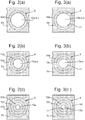
- the sub-images are shown in plan view in Figures 3(a), (b) and (c) for layers 6a, 6b and 6c, respectively (each of Figures 3(a) to (c) showing only a section of the respective opacifying layer including and surrounding region 9, and omitting the remainder of the layer).
- the different sub-images are configured such that once the opacifying layers are arranged on top of one another, as shown in Figure 1(b) , the cumulative effect of the different sub-images is a variation in the optical density of the security print medium across region 9 which appears as the multi-tone image 10, at least when the medium is viewed in transmitted light.
- the order in which the opacifying layers 6a, 6b, 6c and 7 are arranged on the substrate is unimportant since it is their cumulative effect, when all are viewed in combination, which creates the desired image.
- the position of the substrate within the stack of opacifying layers will not affect the image exhibited by the end product and so can be freely selected.
- the multi-tone image 10 in the present embodiment depicts a three-dimensional hemisphere, and is made up of four different tones.
- the innermost circular portion 10a has the lowest optical density (or tone), achieved by providing corresponding gaps in all of the opacifying layers except for layer 7 such that a single opacifying layer is present across portion 10a, and the outermost annular portion 10d has the highest optical density (or tone), achieved by providing gaps in none of the opacifying layers in this portion, such that all four are present here.
- Intermediate annular portions 10b and 10c are provided with respective intermediate optical density / tonal values, achieved by locating gaps in these portions in one of the four opacifying layers and in two of the four opacifying layers, respectively.
- portion 10b has an optical density of 33% and portion 10c an optical density of 66%.
- portion 10a will have an optical density of 0.2, portion 10b an optical density of 0.4, portion 10c an optical density of 0.6 and portion 10d an optical density of 0.8.
- the innermost portion 10a When the medium 1 is viewed in transmitted light (i.e. against a backlight), the innermost portion 10a will appear brightest since its low optical density allows the greatest transmission of light, whilst the outermost portion 10d will appear darkest due to its high optical density. As a result, the centre of the hemisphere appears to protrude out of the plane of the medium 1, towards the viewer, relative to the periphery of the hemisphere which appear farther behind.
- the multi-tone image 10 may or may not be visible in reflected light depending on the optical density of the opacifying layers.
- the inner portion 10a will appear darkest, since it reflects the least light and obstructs the view of the dark background to the smallest degree, whilst the outer portion 10d will appear lightest, since it reflects the most light and largely conceals the underlying dark background.
- the hemisphere appears reversed relative to its appearance in transmitted light, with its centre portion 10a appearing farthest from the viewer and the edge portion 10a appearing nearest.
- each opacifying layer 6a, b, c is arranged.
- the sub-image defined in opacifying layer 6a is shown in Figure 2(a) and it will be seen that this comprises a circular gap extending across the portions 10a,b,c of the multi-tone image, wholly surrounded by the opacifying material of layer 6a.
- the periphery of the circular gap therefore corresponds to the boundary between portion 10c and portion 10d in the multi-tone image 10.
- the opacifying material of layer 6a is present across portion 10d of the multi-tone image (the outer edge of which corresponds to the periphery of region 9, shown for reference).
- the sub-image is defining portions of the desired multi-tone image according to their intended tone (or analogously their optical density): in this sub-image, portions of the multi-tone image having a desired tone of more than 66% up to and including 100% (in this case, portion 10d) are denoted by the presence of opacifying material whilst portions having a desired tone of 66% or less correspond to a gap in the layer.
- the sub-image defined in opacifying layer 6b defines portions of the desired multi-tone image according to a different, larger, tonal range: here, portions of the multi-tone image having a desired tone of more than 33% up to and including 100% (in this case, portions 10c and 10d) are denoted by the presence of opacifying material whilst portions having a desired tone of 33% or less correspond to a gap in the layer.
- the sub-image comprises a circular gap extending across portions 10a and 10b of the multi-tone image, its periphery lying on the boundary between portions 10b and 10c.
- the sub-image defined in opacifying layer 6c defines portions of the desired multi-tone image according to a still larger tonal range: portions of the multi-tone image having a desired tone of more than 0% up to and including 100% (in this case, portions 10c and 10d) are denoted by the presence of opacifying material whilst portions having a desired tone of 0% correspond to a gap in the layer.
- the sub-image comprises a circular gap extending across portion 10a only of the multi-tone image, its periphery lying on the boundary between portions 10a and 10b.
- each sub-image the size of the tonal range defined in each sub-image is different and that each range falls wholly within that of the next sub-image (if they are placed in sequence according to the size of their respective tonal ranges).
- One end point (100%) is the same for each tonal range whilst the other end value varies.
- all of the sub-images are negative images - that is, they each define elements of the desired multi-tone image by the absence of opacifying material against surroundings of that material, rather than vice versa.
- all of the sub-images are binary or "flat" images meaning that the opacifying material is either present or absent across each part of the image (on a scale large enough to be appreciated by the naked eye), and there are no intermediate levels.
- This will be desirable in many cases, especially where a sharp "step-change" in tone is required in the final multi-tone image, e.g. to define a straight edge in the image of an object. If this is not desired, one option to achieve a more gradual change in tone from one portion of the image to the next would be to utilise a greater number of opacifying layers, possibly of lower individual optical density, and a corresponding number of sub-images, arranged so as to achieve a more closely-spaced series of smaller changes in tone. However, this may result in an undesirably thick construction of the security print medium 1 and would also require a corresponding increase in the number of processing steps.
- Figures 3(a), (b) and (c) show alternative sub-images for each of the opacifying layers 6a, b, c respectively in the Figure 1 embodiment, which address this.
- the sub-image for each layer is substantially the same as in the Figure 2 example, defining portions of the multi-tone image according to their desired tone, based on the same different tonal range for each sub-image as previously described, but in this case each of the sub-images itself is multi-tonal, i.e. defining at least one intermediate tone beyond the binary options of "present” or "absent", on a scale visible to the naked eye.
- each sub-image may be formed as a half tone image in which elements of the image are laid down with varying size and/or ink weight to give rise to the required variation in tone.
- this multi-tonal nature of the sub-image is used to replace the sharp periphery of the gap in each opacifying layer with a boundary region 11 in which the tone of the sub-image is intermediate (e.g. 50% fill factor) or gradually increases from zero on the side of the gap to 100% on the other wise. This visually softens the edge of each opacifying layer resulting in a more gradual change between tones in the final multi-tone image.
- all of the sub-images are formed as multi-tone images in this way but this is not essential.
- just one of the sub-images, or a sub-set of the sub-images may be multi-tonal whilst the remaining one or more sub-images may be binary images.
- Multi-tonal sub-images can also be used for purposes other than smoothing transitions between gaps and non-gap portions of a sub-image. More generally, the use of multiple tones in one or more of the sub-images allows for the creation of more complex multi-tonal images once the sub-images are combined since the number of available tones is no longer limited to the number of opacifying layers applied. Rather, by varying the tone across any of the individual sub-images and layering them with further sub-images as necessary, a much larger number of different tones can be created thereby allowing for the formation of a more complex multi-tone image.
- FIG 4 shows a second embodiment of a security print medium 1 formed based on the same principles as described in relation to the first embodiment.
- the construction of the security print medium 1 is largely the same as previously described, common components being denoted in the Figures using the same reference numerals as used above.
- a multi-tone image 10 is formed within a region 9 of the medium 1 and here this again takes the form of a hemisphere.
- a transparent window region 12 is provided to further enhance the security level of the medium 1.
- a window region 12 is provided, this is arranged to surround the multi-tone image 10 (as in the present example), to assist in delimiting the multi-tone image from the rest of the medium 1.
- a transparent window region 12 of this sort can be provided in any of the other embodiments disclosed herein.
- each of the sub-images are now positive images rather than negative images (as in the previous embodiment). That is, inside region 9, each sub-image defines features of the image by the presence of opacifying material against empty surroundings.
- the multi-tone image 10 again has four different tonal levels: on a relative scale this time taking the transparent window region 12 to have an optical density of 0%, the innermost portion 10a has the highest optical density of 100%, and the surrounding annular portions 10b, 10c and 10d have respective optical densities of 75%, 50% and 25%.
- This is achieved by applying each opacifying layer 6a to 6d according to the sub-images shown in Figures 5(a) to (d) respectively.
- Layer 6a is laid down according to the sub-image shown in Figure 5(a) which comprises a circular element extending across the portions 10a to 10d of the multi-tone image 10, being absent only in an annular region corresponding to window 12.
- the sub-image differentiates between portions of the multi-tone image 10 having a relative tonal value (or optical density) in the range of 25% to 100% (in which the opacifying material is present) and portions in the range 0 to less than 25% (in which the opacifying material is absent).
- the sub-image according to which layer 6b is arranged defines portions of the desired multi-tone image according to a different, smaller, tonal range: here, portions of the multi-tone image having a desired tone of 50% up to and including 100% (in this case, portions 10a, 10b and 10c) are denoted by the presence of opacifying material whilst portions having a desired tone of less than 50% correspond to a gap in the layer.
- the sub-image comprises a circular element extending across portions 10a, 10b and 10c of the multi-tone image, surrounding by an annular gap encompassing portion 10d and window region 12.
- the sub-image according to which layer 6c is arranged defines portions of the desired multi-tone image according to a different, still smaller, tonal range: here, portions of the multi-tone image having a desired tone of 75% up to and including 100% (in this case, portions 10a and 10b) are denoted by the presence of opacifying material whilst portions having a desired tone of less than 75% correspond to a gap in the layer.
- the sub-image comprises a circular element extending across portions 10a and 10b of the multi-tone image, surrounding by an annular gap encompassing portions 10c and 10d and window region 12.
- the sub-image according to which layer 6d is arranged defines portions of the desired multi-tone image according to an even smaller tonal range: here, portions of the multi-tone image having a desired tone of 75% up to and including 100% (in this case, portions 10a only) are denoted by the presence of opacifying material whilst portions having a desired tone of less than 75% correspond to a gap in the layer.
- the sub-image comprises a circular element extending across portion 10a of the multi-tone image, surrounding by an annular gap encompassing portions 10b, 10c and 10d and window region 12.
- the innermost portion 10a of the multi-tone image 10 now has the highest optical density whilst the outmost portion 10d has the lowest and window region 12 has a still lower optical density.
- the centre of the hemisphere will appear darkest and therefore furthest from the viewer, giving the impression that the hemisphere is depressed into the plane of the medium 1.
- the innermost portion 10a will now appear lightest and the outermost portions 10d darkest, with the window region 12 taking on the dark colour of the background unmoderated.
- the hemisphere will now appear reversed, having its centre protruding towards the viewer.
- any one or more of the sub-images could be formed as a multi-tonal sub-image in the manner previously described with respect to Figure 3 in order to achieve a more gradual variation in tone.
- Figure 6(a) shows an exemplary raised pattern layer 13 which may be applied over the outermost opacifying layer(s) across the region 9 of the medium 1.
- the raised pattern layer 13 may be applied over the opacifying layer 6d on the first surface of the substrate 5, and/or over the opacifying layer 6c on the second surface of the substrate 5.
- the raised pattern layer may comprise for example a colourless, transparent ink which is applied to the medium 1 in accordance with a screen pattern, the elements of which are large enough to be individual discernible to the naked eye (possibly only under close inspection).
- the raised pattern layer 13 may be applied in the form of an array of line or dot screen elements.
- the raised pattern layer is in the form of a grid of lines as shown.
- the raised pattern layer may be applied by intaglio printing for example and preferably has a latent appearance in that its presence is less visible when the medium is viewed at some angles, relative to others. At certain viewing angles, which depend on the location of the illuminating light source, the raised image pattern will reflect light more strongly to the viewer, and thus become more visible, than at other viewing angles.
- the pattern 13 may or may not be directly related to the content of the multi-tone image 10.
- the raised pattern layer extends across the same region 9 but otherwise does not reflect the features of the multi-tone image, instead comprising a grid pattern, the line weight of which varies from left to right across the region such that it fades to absent on the right side of the region 9.
- the raised pattern layer is tactile (i.e. can be detected by human touch), but this is not essential.
- a raised pattern layer of the sort described above can be used on its own to add complexity to the multi-tone image feature. However it is preferred to integrate the pattern with the multi-tone image by arranging one of the opacifying layers 6 in accordance with a similar screened pattern.
- each opacifying layer 6a to 6d has been laid down in a substantially homogenous manner so as to uniformly cover the desired portions of the substrate 5, at least on a macroscopic scale which is visible to the naked eye.
- such layers may be formed by gravure printing for example, which involves applying the opacifying material from an array of cells, the size of which is typically too small for any resulting pattern structure to be visible to the naked eye.
- one or more of the opacifying layers is formed in accordance with an array of screen elements, such as dots or lines, which are sufficiently large that the screen structure is visible to the naked eye.
- An example of such an opacifying layer 6a' is shown in Figure 6(b) . This could be provided in place of layer 6a or in addition to layer 6a.
- the circular element of the sub-image covering portions 10a to d of the multi-tone image is now applied in accordance with a screen of dots arranged on an orthogonal grid.
- the size of the dot elements varies across the region from small on the left side to large on the right side. This results in a small-scale structure to the tones visible in the multi-tone pattern which interacts with that of the raised pattern layer 13.
- the two screen patterns are selected to be of similar sizes and element shapes, that of raised pattern layer 13 being dominant on the left hand side of the region 9, and that that of opacifying layer 6a' being dominant on the right hand side.
- the multi-tone image will be monochromatic, i.e. displaying multiple shades of the same colour with different darkness levels.
- the opacifying layers are white, off-white or grey
- the multi-tone image 10 will appear in greyscale, with tones varying from white to dark grey or black, with various intermediate grey tones inbetween.
- Figure 7 shows a third embodiment in which the multi-tone image 10 is coloured by the addition of a print 8 of the same image, in this case formed of two print workings 8a and 8b, located on respective surfaces of the polymer substrate 5, under the opacifying layers 6a to 6d on each side.
- the multi-tone image 10 is of a three-dimensional cube and is located in a transparent window region 12 inside the region 9.
- the construction of the medium 1 is substantially the same as in the previous embodiments with a polymer substrate 5 having opacifying layers 6a to 6d applied to each side in accordance with respective sub-images to define the different tones desired in the multi-tone image 10.
- two opacifying layers 6a, 6b are applied to the first surface of the substrate 5, layer 6a defining portions 10a and 10b of the cube, surrounded by a gap corresponding to window 12, and layer 6b being present only in portion 10b of the cube, resulting in that portion having a higher optical density than portion 10a.
- Two further opacifying layers 6c, 6d are provided on the second surface of the substrate 5, layer 6c being defined according to the same sub-image as layer 6b and layer 6d being defined according to the same sub-image as layer 6a.
- more opacifying layers could be provided in accordance with still further different sub-images to increase the complexity of the multi-tone image if desired.
- the print 8 of the multi-tone image 10 comprises two workings 8a, 8b preferably in different colours.
- one of the workings 8a may provide an overall, solid region of one colour (e.g. red) across the whole of the area corresponding to the multi-tone image (i.e. both regions 10a and 10b).
- This combined with the shading achieved by the opacifying layers 6a to 6d will result in an image 10 of a red, three-dimensional cube with the different portions of the image having relatively light or dark shades of red resulting from the different optical densities of the opacifying layers in combination with one another.
- the other working 8b could be identical to the first working 8a, and in the same colour, to increase the intensity of the colour.
- the second working could be in a different colour and configured to provide different elements of the multi-tone image - e.g. the first working could be provided only in portion 10a of the image and the second working only in portion 10b so that two facets of the cube appear in different colours - or could overlap with the first to provide an intermediate colour such as orange where the first working is red and the second yellow.
- one of the workings could be provided in a dark colour such as black and used to provide additional shading to the multi-tone image, e.g. being provided only in the portions of the image which are intended to have the darkest tone.
- Any one or more of the print workings may advantageously itself be multi-tonal, e.g. formed as a half-tone image, to introduce further complexity to the feature.
- the print 8 can be applied using any available application technique and may comprise a single working or a plurality of workings.
- the print 8 could be applied by gravure, flexographic, lithographic or any other available printing technique, or by applying an all-over layer of ink and then selectively removing parts of it to define an image, e.g. by laser ablation or etching.
- the composition forming the image should preferably be at least semi-transparent so that it does not negate the variation in optical density created in the opacifying layers 6.
- the print 8 is located under the opacifying layers - i.e. between the opacifying layers and the polymer substrate 5 (optionally on top of a primer layer), as shown in Figure 7(b) .
- this is not essential and the print could be located between any of the opacifying layers.
- the print 8 be located on the outer surface of the outermost opacifying layers 6b, 6d since in this case its reflective colour may overwhelm the multi-tonal effect of the feature, especially when viewed in reflection.
- a print 8 of this sort can be incorporated into any of the presently disclosed embodiments.
- Figure 8 illustrates a fourth embodiment of a security print medium, showing each layer applied to a polymer substrate 5 separately, in plan view.
- Layers 8a, 6b, 6d and 6f are applied in that order to a first surface of substrate 5
- layers 8b, 6a, 6c and 6e are applied in that order to a second surface of substrate 5 (although as mentioned previously the order of the layers, and on which surface of the substrate each is applied, is unimportant).
- the substrate 5 may carry additional layers on either of its surfaces such as a primer layer, which are not shown here.
- the security print medium comprises six opacifying layers 6a to 6f, each applied according to a different sub-image as illustrated in the Figure.
- opacifying layers will typically be white, here the opacifying material is illustrated in each of layers 6a to 6f as black in order to be visible in the Figure.
- the white portions surrounded by black in each of the sub-images in fact correspond to gaps in the sub-images, and the black portions represent the areas where opacifying material is present.
- Layers 8a and 8b are two workings forming a print 8 in colours contrasting with that of the opacifying layers 6a to 6f, in the same manner as described in connection with Figure 7 above.
- working 8a is a flat (binary) print in purple
- working 8b is a multi-tonal print in black.
- the layers depicted in Figure 8 form a multi-tone image 10 of a three-dimensional twisted loop structure.
- the portion marked F of the loop appears as the front-most part of the object (i.e. projecting towards the viewer), and the portion marked R appears as the rear-most part of the object (i.e. projecting away from the viewer), when the medium 1 is viewed in transmitted light.
- portion F of the image is achieved by arranging portion F of the image to have the lowest optical density, by providing that portion with corresponding gaps in the greatest number of opacifying layers 6a to 6f: indeed, as can be appreciated by comparing the location marked F in layer 6a with the same location in each of layers 6b to 6f, it will be seen that all of the opacifying layers 6a to 6f have an aligned gap across portion F of the image and hence there is no opacifing material present here, only the ink of print workings 8a and 8b. Hence, when viewed in transmitted light, the portion F will appear light and a bright shade of purple.
- the region R is provided with a high optical density by arranging none of the opacifying layers 6a to 6f to have a gap at this location. This can be appreciated by comparing the portion marked R in layer 6f with the same location in each of layers 6a to 6e.
- loop joining portion R to portion F have intermediate tones by virtue of the different number of opacifying layers present in each portion, resulting in a substantially continuous variation in the shade of the image and giving rise to a strong three-dimensional effect.
- each of the sub-images effectively defines portions of the multi-tone image in accordance with different tonal ranges.
- layer 6a defines the portions of the image having the lightest tones (or optical densities), e.g. from 0% to 16%, as a gap, whilst the respective gaps in each of layers 6b, 6c, 6d, 6e and 6f correspond to different tonal value ranges of increasing size - e.g. 0% to 33%; 0% to 50%; 0% to 66%; 0 to 82% and 0 to 95% respectively.
- all of the sub-images 6a to 6f in this example are negative images, whilst the print workings 8a and 8b are both positive images.
- each of the sub-images is a multi-tonal image as described with reference to Figure 3 above, the edges of the gap in each sub-image being "softened” by a boundary region of intermediate tone so that in the final multi-tone image the transition from one tone to the next appears gradual.
- this is not essential.
- print working 8b which is a multi-tonal (e.g. half-toned) working in a dark colour configured to provide additional definition and shading to the twisted loop structure.
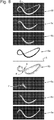
- FIG. 9 A fifth embodiment of a security print medium is shown in Figure 9 , the various layers being depicted individually in plan view in the same manner as in Figure 8 .
- three opacifying layers 6b, 6d and 6f are provided on a first surface of a polymer substrate 5 and three opacifying layers 6a, 6c and 6e are provided on its second surface.
- the white portions surrounded by black in each of the sub-images in fact correspond to gaps in the sub-images, and the black portions represent the areas where opacifying material is present.
- the multi-tonal image comprises a portrait P of a person, a drawing of a building B and a stripe element S, selected parts of which are visible in each sub-image (labelled only in layer 6a for clarity).
- a transparent window 12 surrounds at least part of the portrait P.
- This multi-tone image is designed for viewing in reflected light against a dark background, although it will also be visible in transmitted light (the portrait appearing reversed).
- portions of the image which are intended to appear brightest such as the bridge of the person's nose and his cheekbones, require the highest optical density
- the portions which are to appear darkest such as the shadows under his eyebrows and under his fingers, require the lowest.
- the darkest portions of the image have an optical density of 0%, i.e. the opacifying material is absent in all six layers, meaning that the dark colour of the underlying background is unobscured as can be appreciated by noting that these portions correspond to gaps (i.e. white regions, in the Figures) in every one of the sub-images.
- the brightest portions of the portrait are provided with opacifying material in every one of the sub-images (i.e. black regions, in the Figures).
- sub-images 6a and 6b are the same as one another, as are sub-images 6c and 6d, and 6e and 6f.
- sub-images 6a and b define portions of the multi-tone image with optical densities in the range 0% to less than 33% as gaps;
- sub-images 6c and d define portions with optical densities in the range 0% to less than 66% as gaps, and
- sub-images 6e and f define portions with optical densities in the range 0% to 95% as gaps.
- each of the sub-images is a positive image.
- the order in which the layers are applied to the substrate is unimportant.
- FIG. 9 The construction shown in Figure 9 will result in a monochromatic multi-tone image.
- one or more print workings may be added and examples of these are shown in Figure 10 .
- three print workings 8a, 8b and 8c are shown.
- Working 8a is located on the first surface of substrate 5, underneath opacifying layer 6b shown in Figure 9
- workings 8b and c are located on the second surface of substrate 5, underneath opacifying layer 6a.
- each of the print workings 8a, 8b and 8c is a multi-tonal working in a different colour.
- working 8a may be red, working 8b brown and working 8c blue.
- the print provides multiple colours and additional shading to the multi-tonal image.
- FIG 11 shows a sixth embodiment of a security print medium.
- the various layers forming the security print medium are shown individually in plan view.
- Three opacifying layers 6a,b,c are applied to a first side of a substrate 5, and three additional, optional opacifying layers 7a,b,c to the other.
- the three opacifying layers 7a,b,c are applied uniformly across the substrate 5 and hence do not contribute to the multi-tone image other than to increase its optical density uniformly throughout.
- Each of layers 6a, 6b and 6c is defined according to a different sub-image in the same manner as previously described. In this case the resulting multi-tonal image is a complex pattern of interlocking geometrical elements.
- Different parts of the pattern are provided with different tones by virtue of the number of opacifying layers present at any one location.
- the white portions illustrated in each of the sub-images in fact correspond to gaps in the sub-images, and the black portions represent the areas where opacifying material is present.
- the fine lines visible in layer 6c which align with the centre of the thicker black lines in Figure 6b and the thicker-still black regions in Figure 6c , will ultimately have the highest optical density, whilst the intervening areas will have the lowest optical density.
- different portions of the pattern will appear to protrude towards and away from the viewed, resulting in a three-dimensional effect.
- the order in which the opacifying layers are applied to the substrate is unimportant and the position of the substrate within the stack of layers could also be chosen at will - for instance, the substrate S could be located between layers 6c and 6b, or between layers 7a and 7b, or any other two adjacent layers in the stack.
- each of the sub-images defines portions of the pattern according to their optical density and in this case all of the sub-images are positive images.
- each opacifying layer has an optical density in the range 0.1 to 0.5 (as measured on a transmission densitometer such as the MacBeth TD932, with an aperture area equivalent to that of a circle with a 1mm diameter), more preferably 0.1 to 0.3.
- the opacifying layers each have a brightness L* in CIE L*a*b* colour space of at least 70, preferably at least 80 and more preferably at least 90.
- the opacifying layers should be white, off-white or grey.
- the composition of each opacifying layer may be the same or different to one another.
- one of the opacifying layers on each side of the substrate may comprise electrically conductive particles to reduce the effect of static charge.
- this is the penultimate layer on each side: for example, layers 7 and 6a in Figure 1 , layers 6d and 6c in Figure 8 , layers 6d and 6c in Figure 9 and layers 6b and 7b in Figure 11 .
- the opacifying coating for any of the above embodiments will typically comprise a resin such as a polyurethane based resin, polyester based resin or an epoxy based resin and an opacifying pigment such as titanium dioxide (TiO2), silica, zinc oxide, tin oxide, clays or calcium carbonate.
- a resin such as a polyurethane based resin, polyester based resin or an epoxy based resin
- an opacifying pigment such as titanium dioxide (TiO2), silica, zinc oxide, tin oxide, clays or calcium carbonate.
- the opacifying layers can each be applied by any suitable application process which allows their selective application in accordance with the respective sub-images. Typically, each opacifying layer will be applied by gravure printing. Alternatively, any of flexographic printing, screen printing or lithographic printing may be used.
- the opacifying layers and any print workings should preferably be applied in register with one another, as may be achieved by applying all of them in the same in-line process. As already mentioned, additional layers such as a primer could be applied to the substrate before the opacifying layers (and any optional print workings). Further layers could be applied to the outside of the opacifying layers, such as a protective layer (preferably transparent) or a print-receptive coating.
- security print media can then be processed into security documents.
- the processing steps involved in doing so may be carried out on a separate processing line, typically at a different manufacturing site and optionally by a different entity.
- An example of a security document 100 formed using the security print medium 1 described above in relation to Figure 1 is shown in Figure 12 , (a) in plan view and (b) in cross-section. All of the components already provided as part of the security print medium 1, including multi-tone image 10, are as previously described in relation to Figures 1 , 2 and 3 and hence will not be described again.
- the security document comprises a graphics layer 20 applied in this example to the outer surfaces of the security print medium 1, i.e. to the surface of outermost opacifying layers 6b and 6c. In other cases the graphics layer 20 may be applied only to one or other of the surfaces. As mentioned previously there could be intermediate layers between the opacifying layers and the graphics layer, such as a protective layer or primer.
- the security document is a banknote and hence the graphics layer comprises background security patterns 20a (such as guilloches) as well as identifiers such as denomination information 20b.
- the graphics layer 20 could be applied in a single working or in multiple workings, optionally using more than one printing technique. Any available printing techniques can be utilised for forming the graphics layer as would be applied to a conventional polymer document substrate, e.g. intaglio printing, gravure printing, flexographic printing, lithographic printing etc.
- Figure 12 also illustrates examples of other security devices which may optionally be applied to the security print media to form the security document, such as an optically variable device 21 in window 3, e.g. a moire magnification device, a lenticular device or an integral imaging device as may be formed by cast-curing or laminating a lens array on one side of the polymer substrate 5 and forming image elements on the other.
- an optically variable device 21 in window 3 e.g. a moire magnification device, a lenticular device or an integral imaging device as may be formed by cast-curing or laminating a lens array on one side of the polymer substrate 5 and forming image elements on the other.
- a security device 22 in the form of a patch which has been applied to the surface of the security print media, e.g. by lamination or hot stamping.
- the security device 22 may comprise a diffractive optical element such as a hologram, for example.
- the security documents and security devices of the current invention can optionally be made machine readable by the introduction of detectable materials in any of the layers or by the introduction of separate machine-readable layers.
- Detectable materials that react to an external stimulus include but are not limited to fluorescent, phosphorescent, infrared absorbing, thermochromic, photochromic, magnetic, electrochromic, conductive and piezochromic materials.
Landscapes
- Engineering & Computer Science (AREA)
- Manufacturing & Machinery (AREA)
- Business, Economics & Management (AREA)
- Accounting & Taxation (AREA)
- Finance (AREA)
- Printing Methods (AREA)
- Credit Cards Or The Like (AREA)
- Laminated Bodies (AREA)
Claims (18)
- Support d'impression de sécurité (1) destiné à former des documents de sécurité, comprenant un substrat polymère transparent ou translucide (5) ayant des première et seconde surfaces opposées (5a, 5b) et une pluralité de couches opacifiantes (6) se chevauchant disposées sur la première et/ou la seconde surface du substrat polymère, chacune des couches opacifiantes (6) étant une couche de matériau semi-opaque disposée sensiblement sur toute la superficie du substrat polymère, dans au moins une région du substrat une image multi-tonale (10) étant présentée par la pluralité de couches opacifiantes (6) se chevauchant combinées les unes avec les autres, au moins lorsque le support d'impression de sécurité est visualisé en lumière transmise, chacune de la pluralité de couches opacifiantes (6) se chevauchant ayant un ou des espaces dans lesquels le matériau semi-opaque de la couche est absent, le ou les espaces de chaque couche étant définis selon une sous-image respective différente, les sous-images combinées définissant l'image multi-tonale (10), le nombre de couches opacifiantes (6) qui se chevauchent à un emplacement quelconque variant à travers le substrat, la variation résultante de la densité optique de la pluralité de couches opacifiantes se chevauchant combinées les unes avec les autres donnant lieu aux multiples tons de l'image multi-tonale (10), caractérisé en ce que toutes les sous-images sont différentes versions d'image négative de l'image multi-tonale ou toutes les sous-images sont différentes versions d'image positive de l'image multi-tonale.
- Support d'impression de sécurité selon la revendication 1, dans lequel chaque sous-image définit des parties de l'image multi-tonale (10) qui ont une valeur tonale se situant dans une plage de valeurs tonales respectives, la taille de chaque plage de valeurs tonales respectives étant différente ;
de préférence, lorsque les plages de valeurs tonales des sous-images étant ordonnées selon la taille croissante, chaque plage de valeurs tonales se situant dans la plage de valeurs tonales suivante de la séquence ; et plus préférablement, toutes les plages de valeurs tonales partageant sensiblement la même première valeur finale et différant par leurs secondes valeurs finales. - Support d'impression de sécurité selon l'une quelconque des revendications précédentes, dans lequel au moins certaines des sous-images sont des sous-images multi-tonales, de préférence des sous-images en demi-teintes.
- Support d'impression de sécurité selon l'une quelconque des revendications précédentes, dans lequel toutes les couches opacifiantes (6) ont sensiblement la même couleur les unes par rapport aux autres, de préférence blanc ou gris.
- Support d'impression de sécurité selon l'une quelconque des revendications précédentes, comprenant en outre une impression mono-tonale ou multi-tonale (8) d'au moins une partie de l'image multi-tonale en une ou plusieurs couleurs contrastant visuellement avec les couches opacifiantes (6), située entre au moins une, de préférence la totalité, des couches opacifiantes et du substrat polymère sur leurs première et/ou seconde surfaces, l'impression de l'image multi-tonale étant alignée avec les sous-images dans les couches opacifiantes.
- Procédé selon l'une quelconque des revendications précédentes, dans lequel soit :les sous-images sont conçues de telle sorte qu'un plus grand nombre de couches opacifiantes (6) se chevauchent à des emplacements sur le substrat correspondant à des tons plus sombres dans l'image multi-tonale, par rapport au nombre de couches opacifiantes qui se chevauchent à des emplacements correspondant à des tons plus clairs dans l'image multi-tonale, l'image multi-tonale étant conçue pour une visualisation en lumière transmise ; oules sous-images sont conçues de telle sorte qu'un nombre plus petit des couches opacifiantes (6) se chevauchent à des emplacements sur le substrat correspondant aux tons plus sombres de l'image multi-tonale, par rapport au nombre de couches opacifiantes qui se chevauchent aux emplacements correspondant à des tons plus clairs dans l'image multi-tonale, l'image multi-tonale étant conçue pour une visualisation en lumière réfléchie.
- Support d'impression de sécurité selon l'une quelconque des revendications précédentes, comprenant en outre une ou plusieurs couches opacifiantes supplémentaires (7), chacune comprenant une couche de matériau semi-opaque disposée sensiblement sur toute la superficie du substrat polymère, la ou les couches opacifiantes supplémentaires s'étendant chacune soit de manière continue sur la région du substrat contenant l'image multi-tonale, soit comprenant un espace sensiblement à travers la région.
- Support d'impression de sécurité selon l'une quelconque des revendications précédentes, comprenant en outre au moins une région de fenêtre transparente (12) formée par des espaces alignés dans chacune des couches opacifiantes, l'au moins une région de fenêtre transparente entourant de préférence sensiblement l'image multi-tonale (10).
- Support d'impression de sécurité selon l'une quelconque des revendications précédentes, dans lequel l'image multi-tonale (10) comprend une image d'un objet tridimensionnel, de préférence un modèle géométrique solide ou de filaire, une personne, un animal, un bâtiment ou une autre structure architecturale ou un logo tridimensionnel.
- Document de sécurité (100) comprenant un support d'impression de sécurité (1) selon l'une quelconque des revendications 1 à 8, et au moins une couche graphique (20) appliquée sur la ou les couches opacifiantes la ou les plus externes sur la première et/ou seconde surfaces du substrat polymère, de préférence, le document de sécurité (100) étant un billet de banque, un document d'identification, un passeport, un permis, un chèque, un visa, une estampille ou un certificat.
- Procédé de fabrication d'un support d'impression de sécurité (1), comprenant :la fourniture d'un substrat polymère transparent ou translucide (5) ayant des première et seconde surfaces opposées (5a, 5b) ;l'application d'une pluralité de couches opacifiantes (6) se chevauchant sur les première et/ou seconde surfaces du substrat polymère, chacune des couches opacifiantes étant une couche de matériau semi-opaque disposée sur sensiblement toute la superficie du substrat polymère, chaque couche opacifiante étant appliquée selon une sous-image respective différente sur au moins une région du substrat ;chacune de la pluralité de couches opacifiantes (6) se chevauchant ayant un ou des espaces dans lesquels le matériau semi-opaque de la couche est absent, le ou les espaces de chaque couche étant définis selon une sous-image respective différente, les sous-images combinées définissant une image multi-tonale (10) qui est présentée par la pluralité de couches opacifiantes se chevauchant combinées les unes avec les autres, au moins lorsque le support d'impression de sécurité est visualisé en lumière transmise, le nombre de couches opacifiantes se chevauchant à un emplacement quelconque variant sur le substrat, la variation résultante de la densité optique de la pluralité de couches opacifiantes se chevauchant combinées les unes avec les autres donnant lieu aux multiples tons de l'image multi-tonale, caractérisé en ce que soit toutes les sous-images sont différentes versions d'image négative de l'image multi-tonale soit toutes les sous-images sont différentes versions d'image positive de l'image multi-tonale.
- Procédé de fabrication d'un support d'impression de sécurité selon la revendication 11, dans lequel chaque sous-image définit des parties de l'image multi-tonale qui ont une valeur tonale se situant dans une plage de valeurs tonales respective, la taille de chaque plage de valeurs tonales respective étant différente, de préférence lorsque les plages de valeurs tonales des sous-images sont ordonnées en fonction de la taille croissante, chaque plage de valeurs tonales se situant dans la plage de valeurs tonales suivante de la séquence, plus préférablement toutes les plages de valeurs tonales partageant sensiblement les mêmes premières valeurs finales et différant par leurs secondes valeurs finales.
- Procédé de fabrication d'un support d'impression de sécurité selon la revendication 11 ou 12, dans lequel au moins certaines des sous-images sont des sous-images multi-tonales, de préférence des sous-images en demi-teinte.
- Procédé de fabrication d'un support d'impression de sécurité selon l'une quelconque des revendications 11 à 13, dans lequel toutes les couches opacifiantes (6) sont sensiblement de la même couleur les unes par rapport aux autres, de préférence blanc ou gris.
- Procédé de fabrication d'un support d'impression de sécurité selon l'une quelconque des revendications 11 à 14, comprenant en outre l'application d'une impression mono-tonale ou multi-tonale (8) d'au moins une partie de l'image multi-tonale en une ou plusieurs couleurs qui contrastent visuellement avec les couches opacifiantes, l'impression de l'image multi-tonale étant alignée avec les sous-images des couches opacifiantes, l'impression étant appliquée sur le substrat avant qu'au moins une, de préférence la totalité, des couches opacifiantes soit appliquée.
- Procédé de fabrication d'un support d'impression de sécurité selon l'une quelconque des revendications 11 à 15, comprenant en outre l'application d'une ou plusieurs couches opacifiantes supplémentaires (7) comprenant chacune une couche de matériau semi-opaque disposée sur sensiblement toute la superficie du substrat polymère, la ou les couches opacifiantes supplémentaires s'étendant chacune de manière continue sur la région du substrat contenant l'image multi-tonale ou comprenant un espace sensiblement à travers la région.
- Procédé de fabrication d'un support d'impression de sécurité selon l'une quelconque des revendications 11 à 16, dans lequel la pluralité de couches opacifiantes (6) est appliquée de telle sorte que des espaces dans chacune d'elles s'alignent pour former au moins une région de fenêtre transparente (12), l'au moins une région de fenêtre transparente entourant de préférence sensiblement l'image multi-tonale.
- Procédé de fabrication d'un document de sécurité (100) comprenant :la fabrication d'un support d'impression de sécurité (1) selon le procédé de l'une quelconque des revendications 11 à 17 ; etl'application d'au moins une couche graphique (20) sur la ou les couches opacifiantes la ou les plus à l'extérieur sur les première et/ou seconde surfaces du substrat polymère ;de préférence, le document de sécurité (100) étant un billet de banque, un document d'identification, un passeport, un permis, un chèque, un visa, une estampille ou un certificat.
Applications Claiming Priority (2)
| Application Number | Priority Date | Filing Date | Title |
|---|---|---|---|
| GB1517150.7A GB2542783B (en) | 2015-09-29 | 2015-09-29 | Security print media and method of manufacture thereof |
| PCT/GB2016/052996 WO2017055823A1 (fr) | 2015-09-29 | 2016-09-27 | Support d'impression de sécurité et son procédé de fabrication |
Publications (3)
| Publication Number | Publication Date |
|---|---|
| EP3356152A1 EP3356152A1 (fr) | 2018-08-08 |
| EP3356152B1 true EP3356152B1 (fr) | 2020-01-08 |
| EP3356152B2 EP3356152B2 (fr) | 2025-11-26 |
Family
ID=54544238
Family Applications (1)
| Application Number | Title | Priority Date | Filing Date |
|---|---|---|---|
| EP16777744.0A Active EP3356152B2 (fr) | 2015-09-29 | 2016-09-27 | Support d'impression de sécurité et son procédé de fabrication |
Country Status (7)
| Country | Link |
|---|---|
| EP (1) | EP3356152B2 (fr) |
| CN (1) | CN108290437B (fr) |
| AU (1) | AU2016330005C1 (fr) |
| CA (1) | CA3000613A1 (fr) |
| GB (1) | GB2542783B (fr) |
| MX (1) | MX382647B (fr) |
| WO (1) | WO2017055823A1 (fr) |
Families Citing this family (9)
| Publication number | Priority date | Publication date | Assignee | Title |
|---|---|---|---|---|
| GB2572772B (en) * | 2018-04-10 | 2020-08-19 | De La Rue Int Ltd | Security print media and method of manufacture thereof |
| GB201815779D0 (en) * | 2018-09-27 | 2018-11-14 | De La Rue Int Ltd | Documents and methods of manufacture thereof |
| AU2018101824A4 (en) * | 2018-11-26 | 2019-01-03 | Ccl Secure Pty Ltd | A security feature and method of manufacture thereof |
| GB2596075B (en) | 2020-06-15 | 2025-04-16 | Iq Structures Sro | Composite security element |
| GB2601036B (en) | 2020-09-11 | 2023-05-10 | De La Rue Int Ltd | Security devices and methods of manufacture thereof |
| GB202019383D0 (en) | 2020-12-09 | 2021-01-20 | De La Rue Int Ltd | Security device and method of manfacture thereof |
| CN114639326B (zh) * | 2022-05-20 | 2022-09-13 | 苏州苏大维格科技集团股份有限公司 | 一种呈现立体浮雕图像的精密微结构及其制备方法与应用 |
| GB202300529D0 (en) | 2023-01-13 | 2023-03-01 | De La Rue Int Ltd | Security documents and methods for their manufacture |
| PL448189A1 (pl) * | 2024-04-03 | 2025-10-06 | Polska Wytwórnia Papierów Wartościowych Spółka Akcyjna | Element zabezpieczający, nośnik danych i sposób wykonania nośnika danych |
Citations (8)
| Publication number | Priority date | Publication date | Assignee | Title |
|---|---|---|---|---|
| GB2076337A (en) | 1980-05-14 | 1981-12-02 | Gao Ges Automation Org | Identification cards |
| WO1991007285A1 (fr) | 1989-11-14 | 1991-05-30 | Arjomari Europe | Support plastique filigrane |
| US20050012326A1 (en) | 2001-12-21 | 2005-01-20 | Mario Keller | Security element and method for producing the same |
| EP1674286A1 (fr) | 2004-12-23 | 2006-06-28 | Arjowiggins Security | Élément de sécurité avec un marque digitisé et un support de sécurité ou document avec le même. |
| US20060249042A1 (en) | 2002-04-26 | 2006-11-09 | Giesecke & Devrient Gmbh | Security element and method for producing the same |
| AU2010247373B2 (en) | 2009-05-12 | 2013-07-11 | Giesecke & Devrient Gmbh | Ink-receiving layer having a recess |
| WO2014199296A1 (fr) | 2013-06-10 | 2014-12-18 | Arjowiggins Security | Structure de securite a element optique diffractif |
| WO2015197617A1 (fr) | 2014-06-23 | 2015-12-30 | Arjowiggins Security | Papiers de sécurité et procédés de fabrication |
Family Cites Families (10)
| Publication number | Priority date | Publication date | Assignee | Title |
|---|---|---|---|---|
| JP3718712B2 (ja) * | 2001-08-06 | 2005-11-24 | 独立行政法人 国立印刷局 | 真偽判別可能な印刷物及びその作製方法 |
| DE10226116A1 (de) * | 2001-12-21 | 2003-07-03 | Giesecke & Devrient Gmbh | Sicherheitselement und Verfahren zu seiner Herstellung |
| GB0325729D0 (en) * | 2003-11-04 | 2003-12-10 | Rue De Int Ltd | Security device |
| CH698349B1 (de) * | 2006-11-14 | 2013-06-14 | Securency Int Pty Ltd | Verfahren zum Schutz von Sicherheitsdokumenten vor einer Fälschung. |
| KR101437031B1 (ko) * | 2007-09-03 | 2014-09-03 | 내셔널 프린팅 뷰로우 인코퍼레이티드 어드미니스트레이티브 에이전시 | 위조방지용 인쇄물 |
| DE102010019194A1 (de) * | 2010-05-04 | 2011-11-10 | Giesecke & Devrient Gmbh | Wertdokument mit Ausnehmung |
| CA2808861C (fr) * | 2010-08-23 | 2019-02-12 | Securency International Pty Ltd | Dispositif multicanal optiquement variable |
| EP2699425B1 (fr) * | 2011-04-21 | 2015-08-05 | Altshuler, Vladimir | Étiquette de sécurité (versions), procédé permettant de former une étiquette de sécurité et procédé d'authentification de produit (versions) |
| AU2011101065A4 (en) * | 2011-08-19 | 2011-09-22 | Reserve Bank Of Australia | Composite window security device |
| GB201301790D0 (en) * | 2013-02-01 | 2013-03-20 | Rue De Int Ltd | Security devices and methods of manufacture thereof |
-
2015
- 2015-09-29 GB GB1517150.7A patent/GB2542783B/en active Active
-
2016
- 2016-09-27 WO PCT/GB2016/052996 patent/WO2017055823A1/fr not_active Ceased
- 2016-09-27 AU AU2016330005A patent/AU2016330005C1/en active Active
- 2016-09-27 CN CN201680069490.8A patent/CN108290437B/zh active Active
- 2016-09-27 CA CA3000613A patent/CA3000613A1/fr active Pending
- 2016-09-27 EP EP16777744.0A patent/EP3356152B2/fr active Active
- 2016-09-27 MX MX2018003717A patent/MX382647B/es unknown
Patent Citations (8)
| Publication number | Priority date | Publication date | Assignee | Title |
|---|---|---|---|---|
| GB2076337A (en) | 1980-05-14 | 1981-12-02 | Gao Ges Automation Org | Identification cards |
| WO1991007285A1 (fr) | 1989-11-14 | 1991-05-30 | Arjomari Europe | Support plastique filigrane |
| US20050012326A1 (en) | 2001-12-21 | 2005-01-20 | Mario Keller | Security element and method for producing the same |
| US20060249042A1 (en) | 2002-04-26 | 2006-11-09 | Giesecke & Devrient Gmbh | Security element and method for producing the same |
| EP1674286A1 (fr) | 2004-12-23 | 2006-06-28 | Arjowiggins Security | Élément de sécurité avec un marque digitisé et un support de sécurité ou document avec le même. |
| AU2010247373B2 (en) | 2009-05-12 | 2013-07-11 | Giesecke & Devrient Gmbh | Ink-receiving layer having a recess |
| WO2014199296A1 (fr) | 2013-06-10 | 2014-12-18 | Arjowiggins Security | Structure de securite a element optique diffractif |
| WO2015197617A1 (fr) | 2014-06-23 | 2015-12-30 | Arjowiggins Security | Papiers de sécurité et procédés de fabrication |
Non-Patent Citations (2)
| Title |
|---|
| ANONYMOUS: "Halftone - Wikipedia", 30 June 2020 (2020-06-30), pages 1 - 9, XP055741811, Retrieved from the Internet <URL:https://en.wikipedia.org/w/index.php?title=Halftone&oldid=965256516> |
| RUDOLF L. VAN RENESSE: "Optical Document Security, THIRD EDITION", 2005, ARTECH HOUSE BOSTON/ LONDON, ISBN: 1-58053-258-6, pages: 3PP, 64 - 69, XP055741822 |
Also Published As
| Publication number | Publication date |
|---|---|
| MX382647B (es) | 2025-03-13 |
| MX2018003717A (es) | 2018-09-05 |
| AU2016330005C1 (en) | 2023-03-02 |
| WO2017055823A1 (fr) | 2017-04-06 |
| GB2542783A (en) | 2017-04-05 |
| CN108290437A (zh) | 2018-07-17 |
| GB2542783B (en) | 2018-02-07 |
| AU2016330005B2 (en) | 2021-11-25 |
| AU2016330005A1 (en) | 2018-04-19 |
| CN108290437B (zh) | 2020-02-21 |
| EP3356152B2 (fr) | 2025-11-26 |
| GB201517150D0 (en) | 2015-11-11 |
| CA3000613A1 (fr) | 2017-04-06 |
| EP3356152A1 (fr) | 2018-08-08 |
Similar Documents
| Publication | Publication Date | Title |
|---|---|---|
| EP3356152B1 (fr) | Support d'impression de sécurité et son procédé de fabrication | |
| EP3356153B1 (fr) | Supports d'impression de sécurité et procédé de fabrication associé | |
| EP3096960B2 (fr) | Elements de securite et leurs procedes de fabrication | |
| EP2437946B1 (fr) | Substrat de securite | |
| US20150146297A1 (en) | Security devices and methods of manufacture therefor | |
| EP3655253A1 (fr) | Dispositifs commutateurs optiques | |
| EP3356155B1 (fr) | Supports d'impression de sécurité et leur procédé de fabrication | |
| EP3356154B1 (fr) | Dispositif d'impression de sécurité et son procédé de fabrication | |
| GB2536769A (en) | Security elements and methods of their manufacture |
Legal Events
| Date | Code | Title | Description |
|---|---|---|---|
| STAA | Information on the status of an ep patent application or granted ep patent |
Free format text: STATUS: THE INTERNATIONAL PUBLICATION HAS BEEN MADE |
|
| PUAI | Public reference made under article 153(3) epc to a published international application that has entered the european phase |
Free format text: ORIGINAL CODE: 0009012 |
|
| STAA | Information on the status of an ep patent application or granted ep patent |
Free format text: STATUS: REQUEST FOR EXAMINATION WAS MADE |
|
| 17P | Request for examination filed |
Effective date: 20180406 |
|
| AK | Designated contracting states |
Kind code of ref document: A1 Designated state(s): AL AT BE BG CH CY CZ DE DK EE ES FI FR GB GR HR HU IE IS IT LI LT LU LV MC MK MT NL NO PL PT RO RS SE SI SK SM TR |
|
| AX | Request for extension of the european patent |
Extension state: BA ME |
|
| DAV | Request for validation of the european patent (deleted) | ||
| DAX | Request for extension of the european patent (deleted) | ||
| GRAP | Despatch of communication of intention to grant a patent |
Free format text: ORIGINAL CODE: EPIDOSNIGR1 |
|
| STAA | Information on the status of an ep patent application or granted ep patent |
Free format text: STATUS: GRANT OF PATENT IS INTENDED |
|
| INTG | Intention to grant announced |
Effective date: 20190801 |
|
| RBV | Designated contracting states (corrected) |
Designated state(s): AL AT BE BG CH CY CZ DE DK EE ES FI FR GR HR HU IE IS IT LI LT LU LV MC MK MT NL NO PL PT RO RS SE SI SK SM TR |
|
| GRAS | Grant fee paid |
Free format text: ORIGINAL CODE: EPIDOSNIGR3 |
|
| GRAA | (expected) grant |
Free format text: ORIGINAL CODE: 0009210 |
|
| STAA | Information on the status of an ep patent application or granted ep patent |
Free format text: STATUS: THE PATENT HAS BEEN GRANTED |
|
| AK | Designated contracting states |
Kind code of ref document: B1 Designated state(s): AL AT BE BG CH CY CZ DE DK EE ES FI FR GR HR HU IE IS IT LI LT LU LV MC MK MT NL NO PL PT RO RS SE SI SK SM TR |
|
| REG | Reference to a national code |
Ref country code: CH Ref legal event code: EP |
|
| REG | Reference to a national code |
Ref country code: DE Ref legal event code: R096 Ref document number: 602016027923 Country of ref document: DE |
|
| REG | Reference to a national code |
Ref country code: IE Ref legal event code: FG4D |
|
| REG | Reference to a national code |
Ref country code: AT Ref legal event code: REF Ref document number: 1222213 Country of ref document: AT Kind code of ref document: T Effective date: 20200215 |
|
| REG | Reference to a national code |
Ref country code: NL Ref legal event code: MP Effective date: 20200108 |
|
| REG | Reference to a national code |
Ref country code: LT Ref legal event code: MG4D |
|
| PG25 | Lapsed in a contracting state [announced via postgrant information from national office to epo] |
Ref country code: FI Free format text: LAPSE BECAUSE OF FAILURE TO SUBMIT A TRANSLATION OF THE DESCRIPTION OR TO PAY THE FEE WITHIN THE PRESCRIBED TIME-LIMIT Effective date: 20200108 Ref country code: NO Free format text: LAPSE BECAUSE OF FAILURE TO SUBMIT A TRANSLATION OF THE DESCRIPTION OR TO PAY THE FEE WITHIN THE PRESCRIBED TIME-LIMIT Effective date: 20200408 Ref country code: RS Free format text: LAPSE BECAUSE OF FAILURE TO SUBMIT A TRANSLATION OF THE DESCRIPTION OR TO PAY THE FEE WITHIN THE PRESCRIBED TIME-LIMIT Effective date: 20200108 Ref country code: PT Free format text: LAPSE BECAUSE OF FAILURE TO SUBMIT A TRANSLATION OF THE DESCRIPTION OR TO PAY THE FEE WITHIN THE PRESCRIBED TIME-LIMIT Effective date: 20200531 Ref country code: LT Free format text: LAPSE BECAUSE OF FAILURE TO SUBMIT A TRANSLATION OF THE DESCRIPTION OR TO PAY THE FEE WITHIN THE PRESCRIBED TIME-LIMIT Effective date: 20200108 Ref country code: NL Free format text: LAPSE BECAUSE OF FAILURE TO SUBMIT A TRANSLATION OF THE DESCRIPTION OR TO PAY THE FEE WITHIN THE PRESCRIBED TIME-LIMIT Effective date: 20200108 |
|
| PG25 | Lapsed in a contracting state [announced via postgrant information from national office to epo] |
Ref country code: GR Free format text: LAPSE BECAUSE OF FAILURE TO SUBMIT A TRANSLATION OF THE DESCRIPTION OR TO PAY THE FEE WITHIN THE PRESCRIBED TIME-LIMIT Effective date: 20200409 Ref country code: BG Free format text: LAPSE BECAUSE OF FAILURE TO SUBMIT A TRANSLATION OF THE DESCRIPTION OR TO PAY THE FEE WITHIN THE PRESCRIBED TIME-LIMIT Effective date: 20200408 Ref country code: HR Free format text: LAPSE BECAUSE OF FAILURE TO SUBMIT A TRANSLATION OF THE DESCRIPTION OR TO PAY THE FEE WITHIN THE PRESCRIBED TIME-LIMIT Effective date: 20200108 Ref country code: IS Free format text: LAPSE BECAUSE OF FAILURE TO SUBMIT A TRANSLATION OF THE DESCRIPTION OR TO PAY THE FEE WITHIN THE PRESCRIBED TIME-LIMIT Effective date: 20200508 Ref country code: SE Free format text: LAPSE BECAUSE OF FAILURE TO SUBMIT A TRANSLATION OF THE DESCRIPTION OR TO PAY THE FEE WITHIN THE PRESCRIBED TIME-LIMIT Effective date: 20200108 Ref country code: LV Free format text: LAPSE BECAUSE OF FAILURE TO SUBMIT A TRANSLATION OF THE DESCRIPTION OR TO PAY THE FEE WITHIN THE PRESCRIBED TIME-LIMIT Effective date: 20200108 |
|
| REG | Reference to a national code |
Ref country code: DE Ref legal event code: R026 Ref document number: 602016027923 Country of ref document: DE |
|
| PLBI | Opposition filed |
Free format text: ORIGINAL CODE: 0009260 |
|
| PLAX | Notice of opposition and request to file observation + time limit sent |
Free format text: ORIGINAL CODE: EPIDOSNOBS2 |
|
| PG25 | Lapsed in a contracting state [announced via postgrant information from national office to epo] |
Ref country code: ES Free format text: LAPSE BECAUSE OF FAILURE TO SUBMIT A TRANSLATION OF THE DESCRIPTION OR TO PAY THE FEE WITHIN THE PRESCRIBED TIME-LIMIT Effective date: 20200108 Ref country code: CZ Free format text: LAPSE BECAUSE OF FAILURE TO SUBMIT A TRANSLATION OF THE DESCRIPTION OR TO PAY THE FEE WITHIN THE PRESCRIBED TIME-LIMIT Effective date: 20200108 Ref country code: SK Free format text: LAPSE BECAUSE OF FAILURE TO SUBMIT A TRANSLATION OF THE DESCRIPTION OR TO PAY THE FEE WITHIN THE PRESCRIBED TIME-LIMIT Effective date: 20200108 Ref country code: SM Free format text: LAPSE BECAUSE OF FAILURE TO SUBMIT A TRANSLATION OF THE DESCRIPTION OR TO PAY THE FEE WITHIN THE PRESCRIBED TIME-LIMIT Effective date: 20200108 Ref country code: RO Free format text: LAPSE BECAUSE OF FAILURE TO SUBMIT A TRANSLATION OF THE DESCRIPTION OR TO PAY THE FEE WITHIN THE PRESCRIBED TIME-LIMIT Effective date: 20200108 Ref country code: DK Free format text: LAPSE BECAUSE OF FAILURE TO SUBMIT A TRANSLATION OF THE DESCRIPTION OR TO PAY THE FEE WITHIN THE PRESCRIBED TIME-LIMIT Effective date: 20200108 Ref country code: EE Free format text: LAPSE BECAUSE OF FAILURE TO SUBMIT A TRANSLATION OF THE DESCRIPTION OR TO PAY THE FEE WITHIN THE PRESCRIBED TIME-LIMIT Effective date: 20200108 |
|
| 26 | Opposition filed |
Opponent name: OBERTHUR FIDUCIAIRE SAS / VHP SECURITY PAPER B.V. Effective date: 20201006 |
|
| REG | Reference to a national code |
Ref country code: AT Ref legal event code: MK05 Ref document number: 1222213 Country of ref document: AT Kind code of ref document: T Effective date: 20200108 |
|
| PG25 | Lapsed in a contracting state [announced via postgrant information from national office to epo] |
Ref country code: IT Free format text: LAPSE BECAUSE OF FAILURE TO SUBMIT A TRANSLATION OF THE DESCRIPTION OR TO PAY THE FEE WITHIN THE PRESCRIBED TIME-LIMIT Effective date: 20200108 Ref country code: AT Free format text: LAPSE BECAUSE OF FAILURE TO SUBMIT A TRANSLATION OF THE DESCRIPTION OR TO PAY THE FEE WITHIN THE PRESCRIBED TIME-LIMIT Effective date: 20200108 |
|
| PG25 | Lapsed in a contracting state [announced via postgrant information from national office to epo] |
Ref country code: PL Free format text: LAPSE BECAUSE OF FAILURE TO SUBMIT A TRANSLATION OF THE DESCRIPTION OR TO PAY THE FEE WITHIN THE PRESCRIBED TIME-LIMIT Effective date: 20200108 Ref country code: SI Free format text: LAPSE BECAUSE OF FAILURE TO SUBMIT A TRANSLATION OF THE DESCRIPTION OR TO PAY THE FEE WITHIN THE PRESCRIBED TIME-LIMIT Effective date: 20200108 |
|
| PLBB | Reply of patent proprietor to notice(s) of opposition received |
Free format text: ORIGINAL CODE: EPIDOSNOBS3 |
|
| REG | Reference to a national code |
Ref country code: CH Ref legal event code: PL |
|
| REG | Reference to a national code |
Ref country code: BE Ref legal event code: MM Effective date: 20200930 |
|
| PG25 | Lapsed in a contracting state [announced via postgrant information from national office to epo] |
Ref country code: LU Free format text: LAPSE BECAUSE OF NON-PAYMENT OF DUE FEES Effective date: 20200927 |
|
| PG25 | Lapsed in a contracting state [announced via postgrant information from national office to epo] |
Ref country code: IE Free format text: LAPSE BECAUSE OF NON-PAYMENT OF DUE FEES Effective date: 20200927 Ref country code: LI Free format text: LAPSE BECAUSE OF NON-PAYMENT OF DUE FEES Effective date: 20200930 Ref country code: BE Free format text: LAPSE BECAUSE OF NON-PAYMENT OF DUE FEES Effective date: 20200930 Ref country code: CH Free format text: LAPSE BECAUSE OF NON-PAYMENT OF DUE FEES Effective date: 20200930 |
|
| PG25 | Lapsed in a contracting state [announced via postgrant information from national office to epo] |
Ref country code: TR Free format text: LAPSE BECAUSE OF FAILURE TO SUBMIT A TRANSLATION OF THE DESCRIPTION OR TO PAY THE FEE WITHIN THE PRESCRIBED TIME-LIMIT Effective date: 20200108 Ref country code: MT Free format text: LAPSE BECAUSE OF FAILURE TO SUBMIT A TRANSLATION OF THE DESCRIPTION OR TO PAY THE FEE WITHIN THE PRESCRIBED TIME-LIMIT Effective date: 20200108 Ref country code: CY Free format text: LAPSE BECAUSE OF FAILURE TO SUBMIT A TRANSLATION OF THE DESCRIPTION OR TO PAY THE FEE WITHIN THE PRESCRIBED TIME-LIMIT Effective date: 20200108 |
|
| PG25 | Lapsed in a contracting state [announced via postgrant information from national office to epo] |
Ref country code: MK Free format text: LAPSE BECAUSE OF FAILURE TO SUBMIT A TRANSLATION OF THE DESCRIPTION OR TO PAY THE FEE WITHIN THE PRESCRIBED TIME-LIMIT Effective date: 20200108 Ref country code: MC Free format text: LAPSE BECAUSE OF FAILURE TO SUBMIT A TRANSLATION OF THE DESCRIPTION OR TO PAY THE FEE WITHIN THE PRESCRIBED TIME-LIMIT Effective date: 20200108 Ref country code: AL Free format text: LAPSE BECAUSE OF FAILURE TO SUBMIT A TRANSLATION OF THE DESCRIPTION OR TO PAY THE FEE WITHIN THE PRESCRIBED TIME-LIMIT Effective date: 20200108 |
|
| APBM | Appeal reference recorded |
Free format text: ORIGINAL CODE: EPIDOSNREFNO |
|
| APBP | Date of receipt of notice of appeal recorded |
Free format text: ORIGINAL CODE: EPIDOSNNOA2O |
|
| APAH | Appeal reference modified |
Free format text: ORIGINAL CODE: EPIDOSCREFNO |
|
| APBQ | Date of receipt of statement of grounds of appeal recorded |
Free format text: ORIGINAL CODE: EPIDOSNNOA3O |
|
| P01 | Opt-out of the competence of the unified patent court (upc) registered |
Effective date: 20230517 |
|
| APBU | Appeal procedure closed |
Free format text: ORIGINAL CODE: EPIDOSNNOA9O |
|
| PLAB | Opposition data, opponent's data or that of the opponent's representative modified |
Free format text: ORIGINAL CODE: 0009299OPPO |
|
| PGFP | Annual fee paid to national office [announced via postgrant information from national office to epo] |
Ref country code: DE Payment date: 20250702 Year of fee payment: 10 |
|
| R26 | Opposition filed (corrected) |
Opponent name: OBERTHUR FIDUCIAIRE SAS /VHP SECURITY PAPER B.V. Effective date: 20201006 |
|
| PGFP | Annual fee paid to national office [announced via postgrant information from national office to epo] |
Ref country code: FR Payment date: 20250808 Year of fee payment: 10 |
|
| PUAH | Patent maintained in amended form |
Free format text: ORIGINAL CODE: 0009272 |
|
| STAA | Information on the status of an ep patent application or granted ep patent |
Free format text: STATUS: PATENT MAINTAINED AS AMENDED |
|
| REG | Reference to a national code |
Ref country code: CH Ref legal event code: M12 Free format text: ST27 STATUS EVENT CODE: U-0-0-M10-M12 (AS PROVIDED BY THE NATIONAL OFFICE) Effective date: 20251029 |
|
| 27A | Patent maintained in amended form |
Effective date: 20251126 |
|
| AK | Designated contracting states |
Kind code of ref document: B2 Designated state(s): AL AT BE BG CH CY CZ DE DK EE ES FI FR GR HR HU IE IS IT LI LT LU LV MC MK MT NL NO PL PT RO RS SE SI SK SM TR |
|
| REG | Reference to a national code |
Ref country code: DE Ref legal event code: R102 Ref document number: 602016027923 Country of ref document: DE |