EP3357384A1 - Sol d'une douche - Google Patents
Sol d'une douche Download PDFInfo
- Publication number
- EP3357384A1 EP3357384A1 EP17203550.3A EP17203550A EP3357384A1 EP 3357384 A1 EP3357384 A1 EP 3357384A1 EP 17203550 A EP17203550 A EP 17203550A EP 3357384 A1 EP3357384 A1 EP 3357384A1
- Authority
- EP
- European Patent Office
- Prior art keywords
- groove
- floor
- bottom plate
- shower
- siphon
- Prior art date
- Legal status (The legal status is an assumption and is not a legal conclusion. Google has not performed a legal analysis and makes no representation as to the accuracy of the status listed.)
- Granted
Links
Images





Classifications
-
- A—HUMAN NECESSITIES
- A47—FURNITURE; DOMESTIC ARTICLES OR APPLIANCES; COFFEE MILLS; SPICE MILLS; SUCTION CLEANERS IN GENERAL
- A47K—SANITARY EQUIPMENT; ACCESSORIES THEREFOR, e.g. TOILET ACCESSORIES
- A47K3/00—Baths; Showers; Appurtenances therefor
- A47K3/28—Showers or bathing douches
- A47K3/40—Pans or trays
-
- E—FIXED CONSTRUCTIONS
- E04—BUILDING
- E04F—FINISHING WORK ON BUILDINGS, e.g. STAIRS, FLOORS
- E04F15/00—Flooring
- E04F15/02—Flooring or floor layers composed of a number of similar elements
- E04F15/02177—Floor elements for use at a specific location
- E04F15/02188—Floor elements for use at a specific location for use in wet rooms
-
- E—FIXED CONSTRUCTIONS
- E04—BUILDING
- E04F—FINISHING WORK ON BUILDINGS, e.g. STAIRS, FLOORS
- E04F15/00—Flooring
- E04F15/02—Flooring or floor layers composed of a number of similar elements
- E04F15/08—Flooring or floor layers composed of a number of similar elements only of stone or stone-like material, e.g. ceramics, concrete; of glass or with a top layer of stone or stone-like material, e.g. ceramics, concrete or glass
Definitions
- the present invention relates, on the one hand, to the floor of a shower and, on the other hand, to a building with a bath, the floor of a shower being arranged in the region of a wall.
- showers in various embodiments are well known in the art. So the most widely used is the use of a shower tray as the bottom of a shower, wherein a siphon is flanged to the shower tray by means of a screw connection.
- the shower tray has a drain opening, wherein the siphon is flanged to the edge of the drain opening.
- the siphon itself has to connect to the shower tray in the drain hole a from below into the Drain opening protruding siphon insert with an annular seal on, from the top of the bottom of the shower tray a counter-washer can be screwed.
- the lock ring has a seal on the shower tray seal. In the assembled state of the siphon thus results in an absolutely tight connection between the shower tray on the one hand and the siphon on the other.
- tile or plate showers are known. This is understood to mean a shower in which the tiled floor of the bath extends, for example, into the shower.
- two embodiments are known, namely a first embodiment in which a drainage device is provided in the bottom of the shower, in which respect a plurality of gradient planes, in particular four gradient planes, are provided in the floor around the drainage device.
- the drainage device comprises a drain opening arranged in the bottom and a drainage device, wherein the drainage device comprises a drainage sleeve, with which the drainage device protrudes up to the upper side of the tile mirror.
- On the sleeve sits on the top of a lid, which is provided with individual grooves to ensure the passage of water into the sleeve.
- the sleeve is at the bottom in a drain body and is here above the tile horizontally sealed by a silicone joint.
- the upper collar of the drain body has a sleeve made of a water-impermeable film on the surrounding substructure floor of screed, foam boards etc. is glued below the tile mirror.
- the cuff made of the waterproof foil has a size of about 30 x 30 cm, which means that the cuff extends only over a small part of the bottom surface of the shower.
- the rest of the shower floor is covered with a waterproof coating, which is connected to the cuff.
- the sealing described above is safe against, for example, penetrating through the joints of the tile mirror moisture. However, it is not intended to provide a pressurized water for a permanent seal. Pressing water is formed when, for example, the silicone joint between the tile mirror on the one hand and the drain sleeve, which receives the lid of the drainage device, on the other hand, is damaged. That is, the bottom of such a shower is only partially sealed.
- a line drain is understood to mean a linear drainage slit which extends over a substantial part of the width of the shower, the water being taken up over the entire length of the drainage slit by a rectangular shaped stainless steel gutter and into the sewer by a siphon disposed on the bowl is directed.
- the channel shell with the inserted slotted top of such a line sequence stored on a table that has adjustable height feet.
- the problem here is that the table rises with the height-adjustable feet on the raw concrete floor. That is, before the screed is poured, the table must be set to the required height. After applying the screed, the height of the gutter is no longer changeable. This is not without problems in many cases, especially when it turns out, for example after application of the screed that the screed is wavy, so even a leveling layer must be applied to the screed before the tile mirror or generally expressed, applied to the floor panels of the shower become. Also, similar to the previously described point sequence of a tile or plate shower, it is provided that the groove is sealed only by a silicone joint with respect to the tile mirror. In addition, the problem with such a line drain is that even such a shower has at least two, sometimes even up to five gradient levels with a variety of technically complex to produce, visually unsightly and care technically problematic division joints and fitting plates of the topping.
- a shower panel having a domed top and downcomer having a recessed circumferential groove, the channel having a drain opening at the lowest point.
- the shower plate can be made of natural stone; However, such a shower plate made of natural stone must have a considerable strength, if it is assumed that the channel has a continuous gradient of about 2%, which is common in the sanitary sector. Such a shower plate is therefore expensive and due to the weight only limited manageable. In addition, due to the depth of the gutter, this is expensive to clean.
- the object underlying the invention is therefore to provide a drain device at a bottom of a shower of the type mentioned, which is easy to clean and which has only a low floor level.
- the bottom at least one base plate made of natural stone, artificial stone, porcelain stoneware or ceramic and wherein the bottom has at least one drain device, wherein the drain device comprises a arranged in the bottom plate drain opening, wherein the Bottom plate has at least one groove or groove portions which open into the drain opening, wherein the groove or the groove portions are formed in cross-section arcuate, wherein the groove or the groove sections are polished and have a gradient uniformly over the length of about 0.6 - 1.0 mm without gradient.
- the shower tray dries off by itself within a very short time, thus making cleaning considerably easier.
- non-sloped groove also allows tiles to be used as floor slabs that are 10 mm or less thick.
- the low height of the groove also makes easy cleaning easy.
- the bottom plate has at least one groove which opens into the drainage opening.
- the groove is advantageously located at the lowest point of the shower floor, which is also advantageously located directly on a wall of the shower so that the groove can be positioned immediately in front of the wall.
- the water impinging on the shower floor is conveyed by the slope of the shower tray in the direction of the groove, from where it is also fed through the groove via the drainage device to the sewer. That is, for example, the shower floor made of tiles or floor panels has only a single gradient level. Deepest Point of the slope is the groove.
- the drainage device can in this case, for example, be arranged centrally to the wall immediately in front of the wall, so that the groove on both sides of the drainage device is subdivided into two groove sections which respectively open into the drainage opening of the drainage device. From this it is clear that the groove sections are advantageously arranged along a straight line in the bottom plate.
- the groove or the groove sections should be located directly on the wall of a shower.
- the groove or the groove sections are incorporated directly in front of the wall in the bottom plate, in particular milled.
- the bottom plate may in this case correspond in size to the flat extent of the floor of the shower;
- the tile joints of cement, epoxy resin, silicone o. ⁇ . Between the individual groove sections by manual washing or removal with a suitably shaped profile tool of the shape and the course of the groove profile can be adjusted.
- the drainage device comprises a lid.
- the lid can rest here with a radial distance to the bottom plate on the drain opening or on the siphon.
- the lid can be flush with the surrounding tile mirror with a radial distance to the bottom plate or even projecting in height and the drain opening overlap slightly all around.
- Advantageous in the first case is the optical outer Appearance and in the latter case, the lower overall height, as well as the lower production costs, since the drain body can be flanged directly to the plate and not set lower, for example by means of a fixed in the industrial production under the tile fixed spacer element in the connection area.
- the lid flush with the surrounding tile mirror or the bottom plate to connect directly to the edge or collar of a drain opening in the bottom plate in the region of the groove mouths, which is very advantageous in terms of the external appearance.
- the drain body may be flange-mounted under the tile to an additional spacer element which is industrially fixed under the floor slab.
- the lid can itself have additional openings to increase the drainage capacity at high water flow rates.
- the covers are in all cases releasably connected to the drain body or the bottom plate to allow for revision and cleaning access to all relevant areas and components within the siphon drain body.
- the edge around the drain opening is lower than the grooves or the groove sections.
- a spacer element which consists of a suitable material, eg. B. made of ABS plastic. The Distance element is then fixed in the industrial production of the bottom plate to the underside of the bottom plate, waterproof and non-detachable, z. B. with a suitable adhesive bond.
- the drain device advantageously has a drain opening with a siphon, wherein the siphon in the region of the drain opening at the at least one bottom plate or floor tile, z. B. of natural / artificial stone, porcelain stoneware, ceramics o. ⁇ ., Water-tight, in particular flanged and further here in particular is screwed.
- the connection between the siphon on the one hand and the bottom plate on the other hand this can be done indirectly by, for example, a later discussed spacer element or directly on the bottom plate.
- a drainage device is arranged on a base plate of a tile or plate shower, which ensures absolute tightness with respect to pending water.
- the siphon consists essentially of two parts, namely a drain body, which is attached from below to the bottom plate with a seal at the drain opening, and a lock ring, which is bolted to a resting on the bottom plate with the drain body.
- An advantage of such a known siphon is the low height and in particular the simple standardized assembly.
- the floor panels can be completely prefabricated industrially, so that they must then be placed during assembly only on the flange of the drain body and screwed through the lock ring. It is the same known simple installation as in commercial shower trays.
- the bottom plate rests on the screed or another subfloor, wherein in the area of the siphon of the base floor, z. B. screed, foam boards o. ⁇ ., Is recessed accordingly.
- the advantage of a shower floor with only one base plate is that only one gradient level without additional, disadvantageous dividing joints and fitting plates must be formed.
- the invention also relates to a building with a bath, wherein the bath comprises at least one wall, wherein a shower is arranged in the region of the wall, wherein the shower is characterized by a floor according to one or more of claims 1 to 15.
- the groove or the groove sections are arranged in the base plate in such a way that the edge of the groove or the groove sections substantially closes with the tiles of the wall of the shower. From this it is clear that the edge of the groove is located approximately in a plane to the wall of the shower. In this respect, advantageously, the groove and the groove sections are parallel to the wall.
- the bottom plate itself which preferably extends over the entire surface of the floor of the shower, has a slope in the direction of the groove or the groove sections. This can be accomplished, for example, that the bottom plate is slightly obliquely disposed on the substructure floor screed, rigid foam boards o. ⁇ ., Or in that the sub-floor itself is wedge-shaped.
- the invention is also the use of a siphon as part of a drain device for flanging on a floor plate of a shower.
- the floor 1 of the shower whose shower device, so for example the shower, is not shown, comprises the bottom plate 3, wherein the bottom plate 3 either has a size which may correspond substantially to the size of the floor of the shower or part of a floor with a plurality of floor slabs is.
- the bottom plate 3 is glued to the screed 5 in the adhesive bed 7; the screed itself as a subsoil floor is arranged on the raw concrete floor 9.
- the bottom plate 3 superimposed with one end directly to the designated wall 11 with the wall tiles 12.
- a silicone joint 13 is provided in the transition from the Tiles 12 to the bottom plate 3 .
- a sealing collar 31 is arranged, which has a size of about 30 x 30 cm and extending in the region of the siphon 25. Otherwise, the bottom of the shower to form a further seal 33 is provided with a moisture-impermeable coating.
- the bottom plate is doubled, at least in the area of the siphon 25. Such an approach may be necessary for static reasons, if the bottom plate in the region of the siphon has only a small thickness, as z. B. is the case with tiles.
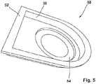
- a spacer element 50 may be provided between the underside of the bottom plate and the siphon, which may be used as a molded part z. B. made of plastic (eg., ABS) may be made ( Fig. 4a . 4b and Fig. 5 ).
- the spacer element 50 has a collar 52 for attachment to the bottom plate 3, and a collar 54 for connection to the drain body of the siphon 25 (FIG. Fig. 4a . Fig. 4b . Fig. 5 ).
- the collar 52 and the collar 54 connects an annular body 56, the height of which is selected so that a sufficient water column can form above the siphon, even if the lid 58 terminates in a thin bottom plate with the top of the bottom plate 3.
- the spacer 50 may be used as part of the bottom plate in the manufacture of the bottom plate glued so that it is firmly connected to the bottom plate. D. h.,
- the siphon may be indirectly connected by the spacer with the bottom plate so far or directly flanged directly to the bottom plate.
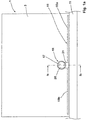
- the bottom plate 3 has a groove, generally designated 15, which finally opens into the drain opening 17 of the drainage device 19.
- the groove can also be called a groove.
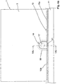
- the groove 15 comprises two groove sections 15a and 15b, each of which opens into the groove outlet 21 of the drainage device 19 with a slight incline. It is provided that the groove portions 15a and 15b are higher than the groove outlet 21, the groove outlet 21 is in turn higher than the edge 23 which extends around the drain opening 17. In the region of the edge 23 which extends around the drain opening, the siphon, generally designated 25, is arranged.
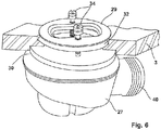
- the siphon 25 comprises a drain body 27 and a lock ring 29, wherein both the drain body 27 and the lock ring 29 have a seal 30, 32 ( Fig. 6 ), which may be connected by a ring land (not shown) firmly together.
- the seal 32 of the locking ring is in this case on the top of the edge 23, whereas the seal 30 of the drain body 27 is disposed adjacent to the underside of the bottom plate in the region of the edge.
- the lock ring 29 also has two screws 34 which are arranged opposite one another on the lock ring, and which serve to connect the lock ring with the drain body 27 through the bottom plate in the region of the rim 23.
- the screws 34 serve to receive the covers 36 and 46, wherein the lid 36 according to Fig. 1b has a radial distance 37 to the bottom plate 3.
- the radial distance 37 serves to discharge the impinging on the bottom plate water.
- the siphon 25 is found, as has already been stated, below the bottom plate 3 within the screed 5.
- the screed 5 In order to accommodate the drain body 27 of the siphon 25 in the screed 5, the screed 5 at the corresponding location on a recess 38.
- the drain body 27 also has a drainage pipe 40 for connection to the sewer pipe (not shown).
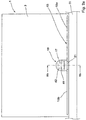
- the in the FIGS. 2a and 2 B shown drain device 19 differs from that according to the FIGS. 1a and 1b in that here the lid 42 extends on the discharge device 19 to the groove 15.
- the groove outlet 21 according to Fig. 2a is so far deep that it extends below the lid 42 into the drain opening 17.
- the lid may optionally, in order to allow the water drain directly from the bottom plate 3, in addition several water passage openings 44 in the form of slots to increase the water drainage performance. Otherwise, the lid 42 is located directly on the bottom plate 3.
- the groove portions 15a, 15b are under the lid with the drain opening 17 in connection.
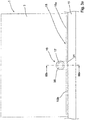
- Fig. 7 shows schematically in a plan view of the floor of a shower, wherein the arrows indicate the flow of water.
- the shower floor has a single slope in the direction of the groove.
- the groove ensures optimal water drainage from the shower tray into the narrow drainage opening during the showering process. This effect is achieved by the vectorial superposition of the orthogonal flow from the sloping plane of the ground against the rising wall with the cross flow in the region of the groove.
- this coupling or superimposition of the impinging flows very advantageous laminar radial flows or streamlines are created in the region of the groove, as a result of which this can be optically advantageously designed very small with maximum absorption capacity.
Landscapes
- Health & Medical Sciences (AREA)
- Public Health (AREA)
- Epidemiology (AREA)
- General Health & Medical Sciences (AREA)
- Sink And Installation For Waste Water (AREA)
Priority Applications (2)
| Application Number | Priority Date | Filing Date | Title |
|---|---|---|---|
| SI201730297T SI3357384T1 (sl) | 2017-02-01 | 2017-11-24 | Pod za prho |
| PL17203550T PL3357384T3 (pl) | 2017-02-01 | 2017-11-24 | Dno prysznica |
Applications Claiming Priority (1)
| Application Number | Priority Date | Filing Date | Title |
|---|---|---|---|
| DE102017101971.5A DE102017101971A1 (de) | 2017-02-01 | 2017-02-01 | Boden einer Dusche |
Publications (2)
| Publication Number | Publication Date |
|---|---|
| EP3357384A1 true EP3357384A1 (fr) | 2018-08-08 |
| EP3357384B1 EP3357384B1 (fr) | 2020-06-03 |
Family
ID=60473343
Family Applications (1)
| Application Number | Title | Priority Date | Filing Date |
|---|---|---|---|
| EP17203550.3A Active EP3357384B1 (fr) | 2017-02-01 | 2017-11-24 | Sol d'une douche |
Country Status (6)
| Country | Link |
|---|---|
| EP (1) | EP3357384B1 (fr) |
| DE (1) | DE102017101971A1 (fr) |
| ES (1) | ES2805879T3 (fr) |
| PL (1) | PL3357384T3 (fr) |
| PT (1) | PT3357384T (fr) |
| SI (1) | SI3357384T1 (fr) |
Families Citing this family (2)
| Publication number | Priority date | Publication date | Assignee | Title |
|---|---|---|---|---|
| AT17331U1 (de) * | 2020-06-02 | 2021-12-15 | Karl Christian Mayr | Nasszelle |
| DE202020105379U1 (de) | 2020-08-06 | 2020-11-03 | Jürgen Beßler | Dusche mit Revisions-Bodenplatte |
Citations (4)
| Publication number | Priority date | Publication date | Assignee | Title |
|---|---|---|---|---|
| US3942199A (en) * | 1972-01-31 | 1976-03-09 | Paul Kollsman | Slip resistant surfaces for bathing fixtures, such as bathtubs and shower receptors |
| DE202004013374U1 (de) * | 2004-08-05 | 2004-10-21 | Probst, Dietrich | Duschboden aus Natur- oder Kunststein |
| US20080190048A1 (en) * | 2001-05-30 | 2008-08-14 | Toto, Ltd. | Bathroom floor panel |
| DE102007056472A1 (de) | 2007-11-22 | 2009-05-28 | Georg Hildebrandt | Verfahren zur Herstellung einer fugenlosen Duschplatte und fugenlose Duschplatte |
Family Cites Families (3)
| Publication number | Priority date | Publication date | Assignee | Title |
|---|---|---|---|---|
| DE19541692C2 (de) | 1995-11-09 | 1999-01-21 | Marmor Stroehmann Gmbh | Duschtasse sowie Verfahren zu deren Herstellung |
| DE202007014302U1 (de) | 2007-10-12 | 2007-12-13 | Albert Kochtokrax Gmbh | Granitflachdusche |
| DE102014104943B4 (de) | 2014-04-08 | 2020-01-02 | Jan Grünewald | Wannenträgeranordnung |
-
2017
- 2017-02-01 DE DE102017101971.5A patent/DE102017101971A1/de not_active Withdrawn
- 2017-11-24 EP EP17203550.3A patent/EP3357384B1/fr active Active
- 2017-11-24 SI SI201730297T patent/SI3357384T1/sl unknown
- 2017-11-24 PT PT172035503T patent/PT3357384T/pt unknown
- 2017-11-24 ES ES17203550T patent/ES2805879T3/es active Active
- 2017-11-24 PL PL17203550T patent/PL3357384T3/pl unknown
Patent Citations (4)
| Publication number | Priority date | Publication date | Assignee | Title |
|---|---|---|---|---|
| US3942199A (en) * | 1972-01-31 | 1976-03-09 | Paul Kollsman | Slip resistant surfaces for bathing fixtures, such as bathtubs and shower receptors |
| US20080190048A1 (en) * | 2001-05-30 | 2008-08-14 | Toto, Ltd. | Bathroom floor panel |
| DE202004013374U1 (de) * | 2004-08-05 | 2004-10-21 | Probst, Dietrich | Duschboden aus Natur- oder Kunststein |
| DE102007056472A1 (de) | 2007-11-22 | 2009-05-28 | Georg Hildebrandt | Verfahren zur Herstellung einer fugenlosen Duschplatte und fugenlose Duschplatte |
Also Published As
| Publication number | Publication date |
|---|---|
| EP3357384B1 (fr) | 2020-06-03 |
| ES2805879T3 (es) | 2021-02-15 |
| DE102017101971A1 (de) | 2018-08-02 |
| SI3357384T1 (sl) | 2020-08-31 |
| PL3357384T3 (pl) | 2020-10-19 |
| PT3357384T (pt) | 2020-08-14 |
Similar Documents
| Publication | Publication Date | Title |
|---|---|---|
| EP3031990B1 (fr) | Siphon de sol | |
| DE60115636T2 (de) | Ein ablauf und eine gebäudestruktur mit einem ablauf | |
| EP1785534B1 (fr) | Bouche d'égout | |
| DE102006007471B4 (de) | Duschbodenelement und Trägerelement dafür, sowie Duschbodenunterbau aus einem Duschbodenelement und einem Trägerelement für bodengleiche Duschen | |
| EP2756137B1 (fr) | Caniveau d'évacuation pour une douche ras du sol | |
| EP1210897B1 (fr) | Cuvette de douche | |
| DE202015006212U1 (de) | Ablaufanordnung | |
| EP1779754A1 (fr) | Planche de douche avec système de canal d'écoulement | |
| DE3627807A1 (de) | Ablaufarmatur fuer einen fliesenfussboden einer sanitaeren brause | |
| EP3357384B1 (fr) | Sol d'une douche | |
| DE29722117U1 (de) | Bodenablauf | |
| DE202006019814U1 (de) | Duschbodenelement für bodengleiche Duschen | |
| EP4012125B1 (fr) | Élément inférieur sanitaire et combinaison d'un élément inférieur sanitaire avec un dispositif mural d'évacuation | |
| EP4173531B1 (fr) | Receveur de douche plain-pied | |
| DE10060870C1 (de) | Runddusche | |
| EP1783285B1 (fr) | Dispositif de drainage ajustable pour blocs sanitaires | |
| DE102019116655B4 (de) | Einbauhilfe für einen Bodenbelag-Begrenzungsrahmen eines Ablaufes | |
| DE102021103470A1 (de) | Sanitärbodenelement und Kombination eines Sanitärbodenelements mit einer Wandablaufvorrichtung | |
| DE202004004277U1 (de) | Duschwanne | |
| EP4310265B1 (fr) | Procédé d'installation d'un élément d'évacuation d'eau et élément d'entrée d'évacuation d'eau destiné à être intégré dans un sol praticable | |
| DE202006019811U1 (de) | Trägerelement für ein Duschbodenelement für bodengleiche Duschen | |
| EP3666992A1 (fr) | Structure de sol d'une douche | |
| DE20020464U1 (de) | Trägerkörper für eine Duschtasse | |
| WO2000058574A1 (fr) | Entonnoir, notamment en matiere plastique, pour avaloirs de chaussee, et son procede de fabrication | |
| DE202023000693U1 (de) | Duschelement für Holzbalkendecken |
Legal Events
| Date | Code | Title | Description |
|---|---|---|---|
| PUAI | Public reference made under article 153(3) epc to a published international application that has entered the european phase |
Free format text: ORIGINAL CODE: 0009012 |
|
| STAA | Information on the status of an ep patent application or granted ep patent |
Free format text: STATUS: THE APPLICATION HAS BEEN PUBLISHED |
|
| AK | Designated contracting states |
Kind code of ref document: A1 Designated state(s): AL AT BE BG CH CY CZ DE DK EE ES FI FR GB GR HR HU IE IS IT LI LT LU LV MC MK MT NL NO PL PT RO RS SE SI SK SM TR |
|
| AX | Request for extension of the european patent |
Extension state: BA ME |
|
| STAA | Information on the status of an ep patent application or granted ep patent |
Free format text: STATUS: REQUEST FOR EXAMINATION WAS MADE |
|
| 17P | Request for examination filed |
Effective date: 20181016 |
|
| RBV | Designated contracting states (corrected) |
Designated state(s): AL AT BE BG CH CY CZ DE DK EE ES FI FR GB GR HR HU IE IS IT LI LT LU LV MC MK MT NL NO PL PT RO RS SE SI SK SM TR |
|
| GRAP | Despatch of communication of intention to grant a patent |
Free format text: ORIGINAL CODE: EPIDOSNIGR1 |
|
| STAA | Information on the status of an ep patent application or granted ep patent |
Free format text: STATUS: GRANT OF PATENT IS INTENDED |
|
| INTG | Intention to grant announced |
Effective date: 20200103 |
|
| GRAS | Grant fee paid |
Free format text: ORIGINAL CODE: EPIDOSNIGR3 |
|
| GRAA | (expected) grant |
Free format text: ORIGINAL CODE: 0009210 |
|
| STAA | Information on the status of an ep patent application or granted ep patent |
Free format text: STATUS: THE PATENT HAS BEEN GRANTED |
|
| AK | Designated contracting states |
Kind code of ref document: B1 Designated state(s): AL AT BE BG CH CY CZ DE DK EE ES FI FR GB GR HR HU IE IS IT LI LT LU LV MC MK MT NL NO PL PT RO RS SE SI SK SM TR |
|
| REG | Reference to a national code |
Ref country code: GB Ref legal event code: FG4D Free format text: NOT ENGLISH |
|
| REG | Reference to a national code |
Ref country code: CH Ref legal event code: EP Ref country code: AT Ref legal event code: REF Ref document number: 1276109 Country of ref document: AT Kind code of ref document: T Effective date: 20200615 |
|
| REG | Reference to a national code |
Ref country code: DE Ref legal event code: R096 Ref document number: 502017005535 Country of ref document: DE |
|
| REG | Reference to a national code |
Ref country code: PT Ref legal event code: SC4A Ref document number: 3357384 Country of ref document: PT Date of ref document: 20200814 Kind code of ref document: T Free format text: AVAILABILITY OF NATIONAL TRANSLATION Effective date: 20200731 |
|
| REG | Reference to a national code |
Ref country code: NL Ref legal event code: FP |
|
| REG | Reference to a national code |
Ref country code: LT Ref legal event code: MG4D |
|
| PG25 | Lapsed in a contracting state [announced via postgrant information from national office to epo] |
Ref country code: SE Free format text: LAPSE BECAUSE OF FAILURE TO SUBMIT A TRANSLATION OF THE DESCRIPTION OR TO PAY THE FEE WITHIN THE PRESCRIBED TIME-LIMIT Effective date: 20200603 Ref country code: FI Free format text: LAPSE BECAUSE OF FAILURE TO SUBMIT A TRANSLATION OF THE DESCRIPTION OR TO PAY THE FEE WITHIN THE PRESCRIBED TIME-LIMIT Effective date: 20200603 Ref country code: NO Free format text: LAPSE BECAUSE OF FAILURE TO SUBMIT A TRANSLATION OF THE DESCRIPTION OR TO PAY THE FEE WITHIN THE PRESCRIBED TIME-LIMIT Effective date: 20200903 Ref country code: GR Free format text: LAPSE BECAUSE OF FAILURE TO SUBMIT A TRANSLATION OF THE DESCRIPTION OR TO PAY THE FEE WITHIN THE PRESCRIBED TIME-LIMIT Effective date: 20200904 Ref country code: LT Free format text: LAPSE BECAUSE OF FAILURE TO SUBMIT A TRANSLATION OF THE DESCRIPTION OR TO PAY THE FEE WITHIN THE PRESCRIBED TIME-LIMIT Effective date: 20200603 |
|
| PG25 | Lapsed in a contracting state [announced via postgrant information from national office to epo] |
Ref country code: LV Free format text: LAPSE BECAUSE OF FAILURE TO SUBMIT A TRANSLATION OF THE DESCRIPTION OR TO PAY THE FEE WITHIN THE PRESCRIBED TIME-LIMIT Effective date: 20200603 Ref country code: RS Free format text: LAPSE BECAUSE OF FAILURE TO SUBMIT A TRANSLATION OF THE DESCRIPTION OR TO PAY THE FEE WITHIN THE PRESCRIBED TIME-LIMIT Effective date: 20200603 Ref country code: BG Free format text: LAPSE BECAUSE OF FAILURE TO SUBMIT A TRANSLATION OF THE DESCRIPTION OR TO PAY THE FEE WITHIN THE PRESCRIBED TIME-LIMIT Effective date: 20200903 Ref country code: HR Free format text: LAPSE BECAUSE OF FAILURE TO SUBMIT A TRANSLATION OF THE DESCRIPTION OR TO PAY THE FEE WITHIN THE PRESCRIBED TIME-LIMIT Effective date: 20200603 |
|
| PG25 | Lapsed in a contracting state [announced via postgrant information from national office to epo] |
Ref country code: AL Free format text: LAPSE BECAUSE OF FAILURE TO SUBMIT A TRANSLATION OF THE DESCRIPTION OR TO PAY THE FEE WITHIN THE PRESCRIBED TIME-LIMIT Effective date: 20200603 |
|
| PG25 | Lapsed in a contracting state [announced via postgrant information from national office to epo] |
Ref country code: RO Free format text: LAPSE BECAUSE OF FAILURE TO SUBMIT A TRANSLATION OF THE DESCRIPTION OR TO PAY THE FEE WITHIN THE PRESCRIBED TIME-LIMIT Effective date: 20200603 Ref country code: EE Free format text: LAPSE BECAUSE OF FAILURE TO SUBMIT A TRANSLATION OF THE DESCRIPTION OR TO PAY THE FEE WITHIN THE PRESCRIBED TIME-LIMIT Effective date: 20200603 Ref country code: SM Free format text: LAPSE BECAUSE OF FAILURE TO SUBMIT A TRANSLATION OF THE DESCRIPTION OR TO PAY THE FEE WITHIN THE PRESCRIBED TIME-LIMIT Effective date: 20200603 |
|
| REG | Reference to a national code |
Ref country code: ES Ref legal event code: FG2A Ref document number: 2805879 Country of ref document: ES Kind code of ref document: T3 Effective date: 20210215 |
|
| PG25 | Lapsed in a contracting state [announced via postgrant information from national office to epo] |
Ref country code: SK Free format text: LAPSE BECAUSE OF FAILURE TO SUBMIT A TRANSLATION OF THE DESCRIPTION OR TO PAY THE FEE WITHIN THE PRESCRIBED TIME-LIMIT Effective date: 20200603 Ref country code: IS Free format text: LAPSE BECAUSE OF FAILURE TO SUBMIT A TRANSLATION OF THE DESCRIPTION OR TO PAY THE FEE WITHIN THE PRESCRIBED TIME-LIMIT Effective date: 20201003 |
|
| REG | Reference to a national code |
Ref country code: DE Ref legal event code: R097 Ref document number: 502017005535 Country of ref document: DE |
|
| PLBE | No opposition filed within time limit |
Free format text: ORIGINAL CODE: 0009261 |
|
| STAA | Information on the status of an ep patent application or granted ep patent |
Free format text: STATUS: NO OPPOSITION FILED WITHIN TIME LIMIT |
|
| PG25 | Lapsed in a contracting state [announced via postgrant information from national office to epo] |
Ref country code: DK Free format text: LAPSE BECAUSE OF FAILURE TO SUBMIT A TRANSLATION OF THE DESCRIPTION OR TO PAY THE FEE WITHIN THE PRESCRIBED TIME-LIMIT Effective date: 20200603 |
|
| 26N | No opposition filed |
Effective date: 20210304 |
|
| PG25 | Lapsed in a contracting state [announced via postgrant information from national office to epo] |
Ref country code: MC Free format text: LAPSE BECAUSE OF FAILURE TO SUBMIT A TRANSLATION OF THE DESCRIPTION OR TO PAY THE FEE WITHIN THE PRESCRIBED TIME-LIMIT Effective date: 20200603 |
|
| PG25 | Lapsed in a contracting state [announced via postgrant information from national office to epo] |
Ref country code: LU Free format text: LAPSE BECAUSE OF NON-PAYMENT OF DUE FEES Effective date: 20201124 |
|
| PG25 | Lapsed in a contracting state [announced via postgrant information from national office to epo] |
Ref country code: MT Free format text: LAPSE BECAUSE OF FAILURE TO SUBMIT A TRANSLATION OF THE DESCRIPTION OR TO PAY THE FEE WITHIN THE PRESCRIBED TIME-LIMIT Effective date: 20200603 Ref country code: CY Free format text: LAPSE BECAUSE OF FAILURE TO SUBMIT A TRANSLATION OF THE DESCRIPTION OR TO PAY THE FEE WITHIN THE PRESCRIBED TIME-LIMIT Effective date: 20200603 |
|
| PG25 | Lapsed in a contracting state [announced via postgrant information from national office to epo] |
Ref country code: MK Free format text: LAPSE BECAUSE OF FAILURE TO SUBMIT A TRANSLATION OF THE DESCRIPTION OR TO PAY THE FEE WITHIN THE PRESCRIBED TIME-LIMIT Effective date: 20200603 |
|
| REG | Reference to a national code |
Ref country code: DE Ref legal event code: R081 Ref document number: 502017005535 Country of ref document: DE Owner name: SMI003 GMBH, DE Free format text: FORMER OWNER: GERLOFF, MICHAEL, 37269 ESCHWEGE, DE Ref country code: DE Ref legal event code: R081 Ref document number: 502017005535 Country of ref document: DE Owner name: ATS BETEILIGUNGSVERWALTUNG GMBH, DE Free format text: FORMER OWNER: GERLOFF, MICHAEL, 37269 ESCHWEGE, DE |
|
| REG | Reference to a national code |
Ref country code: NL Ref legal event code: PD Owner name: SMI003 GMBH; DE Free format text: DETAILS ASSIGNMENT: CHANGE OF OWNER(S), ASSIGNMENT; FORMER OWNER NAME: GERLOFF, MICHAEL Effective date: 20220728 |
|
| REG | Reference to a national code |
Ref country code: GB Ref legal event code: 732E Free format text: REGISTERED BETWEEN 20220804 AND 20220810 |
|
| REG | Reference to a national code |
Ref country code: AT Ref legal event code: PC Ref document number: 1276109 Country of ref document: AT Kind code of ref document: T Owner name: SMI003 GMBH, DE Effective date: 20220913 |
|
| REG | Reference to a national code |
Ref country code: BE Ref legal event code: PD Owner name: SMI003 GMBH; DE Free format text: DETAILS ASSIGNMENT: CHANGE OF OWNER(S), ASSIGNMENT; FORMER OWNER NAME: GERLOFF, MICHAEL Effective date: 20220920 |
|
| REG | Reference to a national code |
Ref country code: SI Ref legal event code: SP73 Owner name: SMI003 GMBH; DE Effective date: 20221011 |
|
| REG | Reference to a national code |
Ref country code: CH Ref legal event code: PK Free format text: BERICHTIGUNGEN |
|
| PGFP | Annual fee paid to national office [announced via postgrant information from national office to epo] |
Ref country code: GB Payment date: 20231130 Year of fee payment: 7 |
|
| PGFP | Annual fee paid to national office [announced via postgrant information from national office to epo] |
Ref country code: SI Payment date: 20231130 Year of fee payment: 7 Ref country code: NL Payment date: 20231129 Year of fee payment: 7 Ref country code: IE Payment date: 20231129 Year of fee payment: 7 Ref country code: FR Payment date: 20231129 Year of fee payment: 7 Ref country code: CZ Payment date: 20231201 Year of fee payment: 7 |
|
| PGFP | Annual fee paid to national office [announced via postgrant information from national office to epo] |
Ref country code: PL Payment date: 20231213 Year of fee payment: 7 |
|
| REG | Reference to a national code |
Ref country code: DE Ref legal event code: R081 Ref document number: 502017005535 Country of ref document: DE Owner name: ATS BETEILIGUNGSVERWALTUNG GMBH, DE Free format text: FORMER OWNER: SMI003 GMBH, 40239 DUESSELDORF, DE |
|
| PGFP | Annual fee paid to national office [announced via postgrant information from national office to epo] |
Ref country code: TR Payment date: 20250310 Year of fee payment: 8 |
|
| REG | Reference to a national code |
Ref country code: NL Ref legal event code: MM Effective date: 20241201 |
|
| GBPC | Gb: european patent ceased through non-payment of renewal fee |
Effective date: 20241124 |
|
| PG25 | Lapsed in a contracting state [announced via postgrant information from national office to epo] |
Ref country code: CZ Free format text: LAPSE BECAUSE OF NON-PAYMENT OF DUE FEES Effective date: 20241124 |
|
| PG25 | Lapsed in a contracting state [announced via postgrant information from national office to epo] |
Ref country code: NL Free format text: LAPSE BECAUSE OF NON-PAYMENT OF DUE FEES Effective date: 20241201 |
|
| REG | Reference to a national code |
Ref country code: SI Ref legal event code: KO00 Effective date: 20241125 |
|
| PG25 | Lapsed in a contracting state [announced via postgrant information from national office to epo] |
Ref country code: GB Free format text: LAPSE BECAUSE OF NON-PAYMENT OF DUE FEES Effective date: 20241124 |
|
| PG25 | Lapsed in a contracting state [announced via postgrant information from national office to epo] |
Ref country code: FR Free format text: LAPSE BECAUSE OF NON-PAYMENT OF DUE FEES Effective date: 20241130 |
|
| PG25 | Lapsed in a contracting state [announced via postgrant information from national office to epo] |
Ref country code: IE Free format text: LAPSE BECAUSE OF NON-PAYMENT OF DUE FEES Effective date: 20241124 |
|
| REG | Reference to a national code |
Ref country code: BE Ref legal event code: PD Owner name: ATS BETEILIGUNGSVERWALTUNG GMBH; DE Free format text: DETAILS ASSIGNMENT: CHANGE OF OWNER(S), ASSIGNMENT; FORMER OWNER NAME: GERLOFF, MICHAEL Effective date: 20250828 |
|
| REG | Reference to a national code |
Ref country code: CH Ref legal event code: U11 Free format text: ST27 STATUS EVENT CODE: U-0-0-U10-U11 (AS PROVIDED BY THE NATIONAL OFFICE) Effective date: 20251201 |
|
| REG | Reference to a national code |
Ref country code: ES Ref legal event code: PC2A Owner name: ATS BETEILIGUNGSVERWALTUNG GMBH Effective date: 20251127 |
|
| PGFP | Annual fee paid to national office [announced via postgrant information from national office to epo] |
Ref country code: PT Payment date: 20251113 Year of fee payment: 9 |
|
| PGFP | Annual fee paid to national office [announced via postgrant information from national office to epo] |
Ref country code: DE Payment date: 20250917 Year of fee payment: 9 |
|
| PGFP | Annual fee paid to national office [announced via postgrant information from national office to epo] |
Ref country code: AT Payment date: 20251120 Year of fee payment: 9 |
|
| PGFP | Annual fee paid to national office [announced via postgrant information from national office to epo] |
Ref country code: IT Payment date: 20251125 Year of fee payment: 9 |
|
| PGFP | Annual fee paid to national office [announced via postgrant information from national office to epo] |
Ref country code: BE Payment date: 20251119 Year of fee payment: 9 |
|
| PGFP | Annual fee paid to national office [announced via postgrant information from national office to epo] |
Ref country code: CH Payment date: 20251201 Year of fee payment: 9 |
|
| PGFP | Annual fee paid to national office [announced via postgrant information from national office to epo] |
Ref country code: ES Payment date: 20251229 Year of fee payment: 9 |
|
| PG25 | Lapsed in a contracting state [announced via postgrant information from national office to epo] |
Ref country code: SI Free format text: LAPSE BECAUSE OF NON-PAYMENT OF DUE FEES Effective date: 20241125 |
|
| PG25 | Lapsed in a contracting state [announced via postgrant information from national office to epo] |
Ref country code: PL Free format text: LAPSE BECAUSE OF NON-PAYMENT OF DUE FEES Effective date: 20241124 |