EP3357896A1 - Corps en céramique lié - Google Patents
Corps en céramique lié Download PDFInfo
- Publication number
- EP3357896A1 EP3357896A1 EP16851641.7A EP16851641A EP3357896A1 EP 3357896 A1 EP3357896 A1 EP 3357896A1 EP 16851641 A EP16851641 A EP 16851641A EP 3357896 A1 EP3357896 A1 EP 3357896A1
- Authority
- EP
- European Patent Office
- Prior art keywords
- bonding layer
- silicon carbide
- silicide
- bonded body
- mass
- Prior art date
- Legal status (The legal status is an assumption and is not a legal conclusion. Google has not performed a legal analysis and makes no representation as to the accuracy of the status listed.)
- Granted
Links
Images

Classifications
-
- C—CHEMISTRY; METALLURGY
- C04—CEMENTS; CONCRETE; ARTIFICIAL STONE; CERAMICS; REFRACTORIES
- C04B—LIME, MAGNESIA; SLAG; CEMENTS; COMPOSITIONS THEREOF, e.g. MORTARS, CONCRETE OR LIKE BUILDING MATERIALS; ARTIFICIAL STONE; CERAMICS; REFRACTORIES; TREATMENT OF NATURAL STONE
- C04B37/00—Joining burned ceramic articles with other burned ceramic articles or other articles by heating
- C04B37/003—Joining burned ceramic articles with other burned ceramic articles or other articles by heating by means of an interlayer consisting of a combination of materials selected from glass, or ceramic material with metals, metal oxides or metal salts
- C04B37/005—Joining burned ceramic articles with other burned ceramic articles or other articles by heating by means of an interlayer consisting of a combination of materials selected from glass, or ceramic material with metals, metal oxides or metal salts consisting of glass or ceramic material
-
- C—CHEMISTRY; METALLURGY
- C04—CEMENTS; CONCRETE; ARTIFICIAL STONE; CERAMICS; REFRACTORIES
- C04B—LIME, MAGNESIA; SLAG; CEMENTS; COMPOSITIONS THEREOF, e.g. MORTARS, CONCRETE OR LIKE BUILDING MATERIALS; ARTIFICIAL STONE; CERAMICS; REFRACTORIES; TREATMENT OF NATURAL STONE
- C04B37/00—Joining burned ceramic articles with other burned ceramic articles or other articles by heating
- C04B37/003—Joining burned ceramic articles with other burned ceramic articles or other articles by heating by means of an interlayer consisting of a combination of materials selected from glass, or ceramic material with metals, metal oxides or metal salts
-
- B—PERFORMING OPERATIONS; TRANSPORTING
- B32—LAYERED PRODUCTS
- B32B—LAYERED PRODUCTS, i.e. PRODUCTS BUILT-UP OF STRATA OF FLAT OR NON-FLAT, e.g. CELLULAR OR HONEYCOMB, FORM
- B32B18/00—Layered products essentially comprising ceramics, e.g. refractory products
-
- C—CHEMISTRY; METALLURGY
- C04—CEMENTS; CONCRETE; ARTIFICIAL STONE; CERAMICS; REFRACTORIES
- C04B—LIME, MAGNESIA; SLAG; CEMENTS; COMPOSITIONS THEREOF, e.g. MORTARS, CONCRETE OR LIKE BUILDING MATERIALS; ARTIFICIAL STONE; CERAMICS; REFRACTORIES; TREATMENT OF NATURAL STONE
- C04B37/00—Joining burned ceramic articles with other burned ceramic articles or other articles by heating
-
- C—CHEMISTRY; METALLURGY
- C04—CEMENTS; CONCRETE; ARTIFICIAL STONE; CERAMICS; REFRACTORIES
- C04B—LIME, MAGNESIA; SLAG; CEMENTS; COMPOSITIONS THEREOF, e.g. MORTARS, CONCRETE OR LIKE BUILDING MATERIALS; ARTIFICIAL STONE; CERAMICS; REFRACTORIES; TREATMENT OF NATURAL STONE
- C04B37/00—Joining burned ceramic articles with other burned ceramic articles or other articles by heating
- C04B37/003—Joining burned ceramic articles with other burned ceramic articles or other articles by heating by means of an interlayer consisting of a combination of materials selected from glass, or ceramic material with metals, metal oxides or metal salts
- C04B37/006—Joining burned ceramic articles with other burned ceramic articles or other articles by heating by means of an interlayer consisting of a combination of materials selected from glass, or ceramic material with metals, metal oxides or metal salts consisting of metals or metal salts
-
- B—PERFORMING OPERATIONS; TRANSPORTING
- B32—LAYERED PRODUCTS
- B32B—LAYERED PRODUCTS, i.e. PRODUCTS BUILT-UP OF STRATA OF FLAT OR NON-FLAT, e.g. CELLULAR OR HONEYCOMB, FORM
- B32B2250/00—Layers arrangement
- B32B2250/02—2 layers
-
- B—PERFORMING OPERATIONS; TRANSPORTING
- B32—LAYERED PRODUCTS
- B32B—LAYERED PRODUCTS, i.e. PRODUCTS BUILT-UP OF STRATA OF FLAT OR NON-FLAT, e.g. CELLULAR OR HONEYCOMB, FORM
- B32B2307/00—Properties of the layers or laminate
- B32B2307/70—Other properties
- B32B2307/752—Corrosion inhibitor
-
- C—CHEMISTRY; METALLURGY
- C04—CEMENTS; CONCRETE; ARTIFICIAL STONE; CERAMICS; REFRACTORIES
- C04B—LIME, MAGNESIA; SLAG; CEMENTS; COMPOSITIONS THEREOF, e.g. MORTARS, CONCRETE OR LIKE BUILDING MATERIALS; ARTIFICIAL STONE; CERAMICS; REFRACTORIES; TREATMENT OF NATURAL STONE
- C04B2237/00—Aspects relating to ceramic laminates or to joining of ceramic articles with other articles by heating
- C04B2237/02—Aspects relating to interlayers, e.g. used to join ceramic articles with other articles by heating
- C04B2237/04—Ceramic interlayers
- C04B2237/08—Non-oxidic interlayers
-
- C—CHEMISTRY; METALLURGY
- C04—CEMENTS; CONCRETE; ARTIFICIAL STONE; CERAMICS; REFRACTORIES
- C04B—LIME, MAGNESIA; SLAG; CEMENTS; COMPOSITIONS THEREOF, e.g. MORTARS, CONCRETE OR LIKE BUILDING MATERIALS; ARTIFICIAL STONE; CERAMICS; REFRACTORIES; TREATMENT OF NATURAL STONE
- C04B2237/00—Aspects relating to ceramic laminates or to joining of ceramic articles with other articles by heating
- C04B2237/02—Aspects relating to interlayers, e.g. used to join ceramic articles with other articles by heating
- C04B2237/04—Ceramic interlayers
- C04B2237/08—Non-oxidic interlayers
- C04B2237/083—Carbide interlayers, e.g. silicon carbide interlayers
-
- C—CHEMISTRY; METALLURGY
- C04—CEMENTS; CONCRETE; ARTIFICIAL STONE; CERAMICS; REFRACTORIES
- C04B—LIME, MAGNESIA; SLAG; CEMENTS; COMPOSITIONS THEREOF, e.g. MORTARS, CONCRETE OR LIKE BUILDING MATERIALS; ARTIFICIAL STONE; CERAMICS; REFRACTORIES; TREATMENT OF NATURAL STONE
- C04B2237/00—Aspects relating to ceramic laminates or to joining of ceramic articles with other articles by heating
- C04B2237/02—Aspects relating to interlayers, e.g. used to join ceramic articles with other articles by heating
- C04B2237/16—Silicon interlayers
-
- C—CHEMISTRY; METALLURGY
- C04—CEMENTS; CONCRETE; ARTIFICIAL STONE; CERAMICS; REFRACTORIES
- C04B—LIME, MAGNESIA; SLAG; CEMENTS; COMPOSITIONS THEREOF, e.g. MORTARS, CONCRETE OR LIKE BUILDING MATERIALS; ARTIFICIAL STONE; CERAMICS; REFRACTORIES; TREATMENT OF NATURAL STONE
- C04B2237/00—Aspects relating to ceramic laminates or to joining of ceramic articles with other articles by heating
- C04B2237/30—Composition of layers of ceramic laminates or of ceramic or metallic articles to be joined by heating, e.g. Si substrates
- C04B2237/32—Ceramic
- C04B2237/36—Non-oxidic
- C04B2237/365—Silicon carbide
-
- C—CHEMISTRY; METALLURGY
- C04—CEMENTS; CONCRETE; ARTIFICIAL STONE; CERAMICS; REFRACTORIES
- C04B—LIME, MAGNESIA; SLAG; CEMENTS; COMPOSITIONS THEREOF, e.g. MORTARS, CONCRETE OR LIKE BUILDING MATERIALS; ARTIFICIAL STONE; CERAMICS; REFRACTORIES; TREATMENT OF NATURAL STONE
- C04B2237/00—Aspects relating to ceramic laminates or to joining of ceramic articles with other articles by heating
- C04B2237/50—Processing aspects relating to ceramic laminates or to the joining of ceramic articles with other articles by heating
- C04B2237/59—Aspects relating to the structure of the interlayer
- C04B2237/597—Aspects relating to the structure of the interlayer whereby the interlayer is continuous but porous, e.g. containing hollow or porous particles, macro- or micropores or cracks
-
- C—CHEMISTRY; METALLURGY
- C04—CEMENTS; CONCRETE; ARTIFICIAL STONE; CERAMICS; REFRACTORIES
- C04B—LIME, MAGNESIA; SLAG; CEMENTS; COMPOSITIONS THEREOF, e.g. MORTARS, CONCRETE OR LIKE BUILDING MATERIALS; ARTIFICIAL STONE; CERAMICS; REFRACTORIES; TREATMENT OF NATURAL STONE
- C04B2237/00—Aspects relating to ceramic laminates or to joining of ceramic articles with other articles by heating
- C04B2237/50—Processing aspects relating to ceramic laminates or to the joining of ceramic articles with other articles by heating
- C04B2237/70—Forming laminates or joined articles comprising layers of a specific, unusual thickness
- C04B2237/708—Forming laminates or joined articles comprising layers of a specific, unusual thickness of one or more of the interlayers
-
- C—CHEMISTRY; METALLURGY
- C04—CEMENTS; CONCRETE; ARTIFICIAL STONE; CERAMICS; REFRACTORIES
- C04B—LIME, MAGNESIA; SLAG; CEMENTS; COMPOSITIONS THEREOF, e.g. MORTARS, CONCRETE OR LIKE BUILDING MATERIALS; ARTIFICIAL STONE; CERAMICS; REFRACTORIES; TREATMENT OF NATURAL STONE
- C04B2237/00—Aspects relating to ceramic laminates or to joining of ceramic articles with other articles by heating
- C04B2237/50—Processing aspects relating to ceramic laminates or to the joining of ceramic articles with other articles by heating
- C04B2237/78—Side-way connecting, e.g. connecting two plates through their sides
Definitions
- the present invention relates to a ceramic bonded body.
- silicon carbide ceramics Since silicon carbide ceramics has excellent characteristics, such as high mechanical strength, heat resistance and corrosion resistance, they are used in wide fields. Furthermore, in recent years, as apparatuses and facilities equipped with members required to have these characteristics are made larger in size, the members themselves are required to be larger and longer and the shapes of the members are also required to be more complicated. However, it has been difficult to integrally form large, long and complicated moldings. Accordingly, countermeasures for the enlargement and elongation of the members themselves and for the complications in the shapes of the members have been taken by mutually bonding a plurality of sintered bodies.
- Patent Literature 1 has proposed a bonded body in which two or more silicon carbide ceramics members are bonded with silicon.
- Patent Literature 1 Japanese Unexamined Patent Publication JP-A 2001-261459
- a ceramic bonded body of the present disclosure includes a first silicon carbide ceramics, a second silicon carbide ceramics, and a bonding layer between the first silicon carbide ceramics and the second silicon carbide ceramics.
- the bonding layer contains 25 mass% or more metallic silicon and 25 mass% or more silicon carbide with respect to 100 mass% of all components in the bonding layer, and a total of the metallic silicon and the silicon carbide is 75 mass% or more.
- the bonding layer further contains at least one of nickel silicide and chromium silicide.
- the ceramic bonded body of the disclosure has high corrosion resistance and durability.
- the ceramic bonded body of the disclosure will be described below in detail with reference to the drawings.
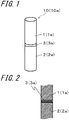
- FIG. 1 is a perspective view showing an example of the ceramic bonded body of the disclosure.
- FIG. 2 is a sectional view showing a bonding portion of the ceramic bonded body shown in FIG. 1 .
- FIG. 3 is a perspective view showing another example of the ceramic bonded body of the disclosure.
- FIG. 4 is a sectional view showing the bonding portion of the ceramic bonded body shown in FIG. 3 .
- the silicon carbide ceramics constituting the ceramic bonded body 10 of the disclosure is ceramics in which silicon carbide occupies 70 mass% or more assuming all components constituting the ceramics as 100 mass%.
- the judgment as to whether the ceramics is silicon carbide ceramics can be confirmed by using the following method. First, the existence of silicon carbide is confirmed by making measurements using an X-ray diffraction (XRD) apparatus and by performing identification using a JCPDS card depending on the obtained value of 2 ⁇ (2 ⁇ is a diffraction angle). Next, the quantitative analysis of silicon is performed using an ICP (Inductively Coupled Plasma) emission spectroscopic analyzer. Next, the content of the silicon measured using the ICP is calculated in terms of silicon carbide; in the case where the content of the silicon carbide is 70 mass% or more, the ceramics is silicon carbide ceramics.
- XRD X-ray diffraction
- ICP Inductively Coupled Plasma
- the bonding layer 3 in the ceramic bonded body 10 of the disclosure contains 25 mass% or more metallic silicon, and 25 mass% or more silicon carbide assuming all components constituting the bonding layer as 100 mass%, and a total of the metallic silicon and the silicon carbide is 75 mass% or more. Since this composition is satisfied, the ceramic bonded body 10 of the disclosure has high bonding strength and durability.
- the reason why the ceramic bonded body 10 of the disclosure has high bonding strength is that, since the above-mentioned composition is satisfied, metallic silicon with good wettability with silicon carbide is present around the silicon carbide serving as aggregate, and silicon carbide grains are bonded, and the voids around the silicon carbide grains become scarce. Since the bonding layer 3 contains silicon carbide and the thermal expansion coefficient of the silicon carbide ceramics is nearly equal to that of the bonding layer 3, the ceramic bonded body 10 of the disclosure is also excellent in high-temperature strength.
- the bonding layer 3 constituting the ceramic bonded body 10 of the disclosure further contains at least one of nickel silicide and chromium silicide. Since this composition is satisfied, the bonding strength of the ceramic bonded body 10 of the disclosure is less prone to be lowered even if the bonded body is exposed to a working environment of corrosive gas and liquid for a long time. Since the bonding strength of the bonded body is less prone to be lowered even if it is exposed to a working environment of corrosive gas and liquid for a long time as described above, the ceramic bonded body 10 of the disclosure is excellent in corrosion resistance. Furthermore, since the ceramic bonded body 10 of the disclosure is excellent in corrosion resistance, in the configuration of the ceramic bonded body 10b shown in FIGS. 3 and 4 , the through hole 4 can be used as a flowing passage, and corrosive gas and liquid can be made to flow through this flowing passage.
- the reason why the bonding strength of the ceramic bonded body 10 of the disclosure is less prone to be lowered even if the bonded body is exposed to a working environment of corrosive gas and liquid for a long time is that nickel silicide and chromium silicide have high corrosion resistance to acidic and alkaline corrosive gases and liquids.
- the bonding strength is improved in the case where the bonding layer 3 contains at least one of nickel silicide and chromium silicide. Although the reason is unknown, it is assumed that nickel silicide and chromium silicide have high chemical affinity to metallic silicon and silicon carbide and are firmly combined with them and that, even if a crack occurs in the bonding layer 3, the development of the crack is blocked by the nickel silicide and the chromium silicide.
- the bonding layer 3 contains metallic silicon and silicon carbide using an energy dispersive spectrometer (EDS) attached to a scanning electron microscope (SEM). More specifically, the cross section in which the bonding layer 3 can be confirmed is finished to a mirror finished surface using an abrasive agent such as diamond abrasive grains. Next, this mirror finished surface is used as a measuring surface, the bonding layer 3 is observed with the SEM, and the crystal grains confirmed in the observation region and portions other than the crystal grains using the EDS attached to the SEM are irradiated with X-rays. After that, in the case where the existence of silicon and carbon in the crystal grains is confirmed and that the existence of silicon in the portions other than the crystal grains is confirmed, it can be said that the bonding layer 3 contains metallic silicon and silicon carbide.
- EDS energy dispersive spectrometer
- SEM scanning electron microscope
- the bonding layer 3 contains metallic silicon and silicon carbide using an electron probe micro analyzer (EPMA).
- EPMA electron probe micro analyzer
- the following method can be used to confirm whether the bonding layer 3 contains at least one of nickel silicide and chromium silicide.
- the XRD is used to measure the bonding layer 3.
- identification of the obtained value of 2 ⁇ with the JCPDS card can confirm whether the bonding layer contains nickel silicide or chromium silicide.
- the surface analysis of the bonding layer 3 is performed using EPMA and a region in which the existence of nickel is confirmed is overlapped at least partly with a region in which the existence of silicon is confirmed, it can be decided that the bonding layer 3 contains nickel silicide.
- the region in which the existence of chromium is confirmed is overlapped at least partly with the region in which the existence of silicon is confirmed, it can be said that the bonding layer 3 contains chromium silicide.
- the contents of the nickel silicide and the chromium silicide in the bonding layer 3 may merely be calculated by using the following method.
- nickel silicide and chromium silicide are contained in the bonding layer 3 by using the above-mentioned method in which the above-mentioned XRD is used, and their chemical formulas are specified.
- the case in which the chemical formula of the nickel silicide contained in the bonding layer 3 is NiSi 2 and the chemical formula of the chromium silicide contained therein is CrSi 2 will be described below.
- the quantitative analysis of nickel (Ni) and chromium (Cr) contained in the bonding layer 3 is performed using the ICP.
- the content of the nickel measured using the ICP is calculated in terms of NiSi 2 , whereby the content of NiSi 2 can be calculated. Furthermore, the content of the chromium measured using the ICP is calculated in terms of CrSi 2 , whereby the content of CrSi 2 can be calculated.
- the content of the entire silicon (Si) contained in the bonding layer 3 is obtained using the ICP.
- the content of the carbon (C) contained in the bonding layer 3 is obtained by making measurement using a carbon analyzer.
- the content of silicon carbide (SiC) is obtained by calculating the content value of C in terms of SiC.
- the content of Si in the SiC is obtained by subtracting the content of C from the content of SiC. Furthermore, the contents of Si in NiSi 2 and CrSi 2 are similarly obtained from the contents of NiSi 2 and CrSi 2 calculated by using the above-mentioned measurement method. And then, the content of metallic silicon (Si) can be obtained by subtracting the contents of Si in SiC, NiSi 2 and CrSi 2 from the content of entire silicon contained in the bonding layer 3 obtained by making measurement using the ICP.
- the total content of the nickel silicide and the chromium silicide in the bonding layer 3 may be 2 mass% or more and 18 mass% or less in terms of NiSi 2 and CrSi 2 assuming all components constituting the bonding layer 3 as 100 mass%. In the case where this composition is satisfied, the ceramic bonded body 10 of the disclosure has higher bonding strength and corrosion resistance.
- the dispersion degree of the nickel silicide and the chromium silicide in the bonding layer 3 may be not less than 0.4 and not more than 0.8. In the case where this composition is satisfied, the nickel silicide and chromium silicide are present while being dispersed appropriately in the bonding layer 3, whereby the ceramic bonded body 10 of the disclosure is more excellent in corrosion resistance.
- the dispersion degree is herein a value obtained by dividing the standard deviation of the distance between the centers of gravity by the average value of the distance between the centers of gravity, the value being derived by analyzing the image obtained by observing the cross section of the bonding layer 3 by using a method referred to as the gravity center distance method of image analysis software "A-ZO KUN" (registered trademark, produced by Asahi Kasei Engineering Corporation).
- the image obtained by observing the cross section of the bonding layer 3 indicates an image obtained by incorporating a photograph in which nickel silicide and chromium silicide are painted in black in a photograph taken after the cross section wherein the bonding layer 3 can be confirmed is finished to a mirror finished surface using an abrasive agent such as diamond abrasive grains and this mirror finished surface is observed using a metallurgical microscope at 500-fold magnification.
- analysis conditions for example, it may merely be set that the brightness of grains is “dark”, that the method of binarization is “manual”, that the elimination of small figures is “0 ⁇ m” and that the threshold is 1.2 to 1.6 times the peak value of the histogram indicating the brightness of each point (each pixel) in the image.
- the bonding layer 3 in the ceramic bonded body 10 of the disclosure may contain silicon carbide grains, and the dispersion degree of the silicon carbide grains may be not less than 0.3 and not more than 0.9.
- the silicon carbide grains are herein crystal grains in which the existence of silicon and carbon has been confirmed using the EDS in the method for confirming the composition of the above-mentioned bonding layer 3.
- the ceramic bonded body 10 of the disclosure has higher bonding strength.
- a method similar to that used to calculate the dispersion degrees of nickel silicide and chromium silicide may merely be executed using an image obtained by incorporating a photograph in which silicon carbide grains are painted in black.
- the area ratio occupied by nickel silicide and chromium silicide having an equivalent circle diameter of 10 ⁇ m or more may be 7 area% or more and 39 area%. If this composition is satisfied, the ceramic bonded body 10 of the disclosure maintains high bonding strength, and even if a crack occurs in the bonding layer 3 and is developed, since the nickel silicide and chromium silicide having an equivalent circle diameter of 10 ⁇ m have a function of blocking the development of the crack, the ceramic bonded body has further higher bonding strength.
- the area ratio occupied by nickel silicide and chromium silicide having an equivalent circle diameter of 10 ⁇ m or more in the bonding layer 3 can be obtained by applying the particle analyzing method of the image analysis software "A-ZO KUN" as in the case where the dispersion degrees of nickel silicide and chromium silicide are calculated.
- the porosity in the bonding layer 3 may be 0.8% or less. If this composition is satisfied, pores serving as starting points of cracks are reduced in the bonding layer 3, whereby the ceramic bonded body 10 of the disclosure has still further higher bonding strength. Furthermore, in the case where the porosity in the bonding layer 3 is 0.8% or less, since the surface area of the bonding layer 3 is reduced, when the bonding layer is exposed to a working environment of corrosive gas and liquid, the penetration speed of the corrosive gas and liquid into the bonding layer 3 is lowered. Hence, in the case where the porosity in the bonding layer 3 is 0.8% or less, the bonding layer has higher corrosion resistance.
- the porosity in the bonding layer 3 can be obtained by applying the particle analyzing method of the image analysis software "A-ZO KUN" as in the case where the dispersion degrees of nickel silicide and chromium silicide are calculated.
- the first silicon carbide ceramics 1 and the second silicon carbide ceramics 2 are prepared.
- metallic powder selected from at least one of metallic silicon powder, silicon carbide powder, nickel powder and chromium powder, an organic solvent, such as terpineol, and ethyl cellulose or acrylic binder are put in the container of a stirring defoaming apparatus. After that, the container is rotated to perform stirring and defoaming, thereby preparing a paste to be formed into the bonding layer 3.
- the ratios of the respective powder materials are adjusted, assuming all components constituting the bonding layer 3 as 100 mass%, so that the ratio of the metallic silicon is 25 mass% or more, so that the ratio of the silicon carbide is 25 mass% or more, so that the ratio of the total of metallic silicon and silicon carbide is 75 mass% or more, and so that the rest is at least one of nickel silicide and chromium silicide.
- the additive amounts of the organic solvent and the binder are for example 1.2 to 23.3 mass parts and 3.1 to 32.7 mass parts, respectively, when the total amount of the respective powder materials (metallic silicon powder, silicon carbide powder and metallic powder) is 100 mass parts.
- the average particle diameter of the metallic powder is 8 ⁇ m or less, and when the metallic powder having this small average particle diameter is used, nickel and chromium react with the metallic silicon more sufficiently, thereby being formed into nickel silicide and chromium silicide, respectively.
- the respective bonding faces face together, and pressure is applied from a direction perpendicular to the bonding faces.
- pressure the own weight of the first silicon carbide ceramics 1 or the second silicon carbide ceramics 2 may be used.
- the paste to be formed into the bonding layer 3 is dried under the conditions that the retention temperature is not lower than 80°C and not higher than 300°C and that the retention time is not shorter than 4 hours and not longer than 16 hours.
- heat treatment is performed under the conditions that the pressure is 1 atm, the retention temperature is not lower than 1400°C and not higher than 1500°C and that the retention time is not shorter than 30 minutes and not longer than 90 minutes under vacuum atmosphere or inert gas atmosphere, such as argon atmosphere, whereby the ceramic bonded body 10 of the disclosure is obtained.
- 0.1 to 1.0 mass parts of a dispersant may be added to the total amount of 100 mass parts of the respective powder materials (metallic silicon powder, silicon carbide powder and metallic powder).
- the dispersant is added in this way, the nickel silicide and the chromium silicide can be caused to be present while being dispersed without being aggregated.
- silicon carbide powder having an average particle diameter of 2 to 10 ⁇ m may be used, and 0.1 to 1.0 mass parts of a dispersant may be added to the total amount of 100 mass parts of the respective powder materials (metallic silicon powder, silicon carbide powder and metallic powder).
- metallic powder adjusted so that nickel powder and chromium powder having an equivalent circle diameter of 5 ⁇ m or more is set to not less than 5 mass% and not more than 30 mass% may be used.
- the bonding layer may be produced under the following conditions. First, only chromium powder is used as metallic powder. In the case where only the chromium powder is used in this way, since chromium reacts with metallic silicon more rapidly than nickel and silicide is formed in the initial stage of the heat treatment, molten metallic silicon easily fills the pores after the initial stage of the heat treatment.
- the stirring defoaming apparatus is operated so as rotate clockwise at a rotation speed of 2000 rpm for 2 to 20 minutes and then operated so as to rotate counterclockwise at a rotation speed of 2200 rpm for 2 to 20 minutes, whereby the porosity in the bonding layer 3 becomes 0.8% or less.
- the first silicon carbide ceramics and the second silicon carbide ceramics having a rectangular columnar shape were prepared.
- the thickness of the bonding layer was 200 ⁇ m, and the ceramic bonded body was formed into a shape from which a test piece having dimensions conforming to JIS R 1624-2010 and having a bonding layer positioned at the center was capable of being cut out.
- metallic silicon powder, silicon carbide powder having an average particle diameter of 1 ⁇ m, nickel powder or chromium powder having an average particle diameter of 4 ⁇ m, terpineol serving as an organic solvent, and ethyl cellulose serving as a binder were put in a container of a stirring defoaming apparatus, and then the container was rotated to perform stirring and defoaming, thereby producing paste to be formed into a bonding layer.
- the ratios of the metallic silicon powder, the silicon carbide powder and the nickel powder or the chromium powder were adjusted so that the metallic silicon, the silicon carbide, the nickel silicide or the chromium silicide had the contents shown in Table 1 assuming all components constituting the bonding layer as 100 mass%. Furthermore, the amounts of the organic solvent and the binder were set to 15.3 mass parts and 7.6 mass parts, respectively, when the total amount of the respective powder materials (metallic silicon powder, silicon carbide powder and nickel powder or chromium powder) was 100 mass parts.
- the stirring using the stirring defoaming apparatus was performed by clockwise rotation at a rotation speed of 2000 rpm for 10 minutes and by counterclockwise rotation at a rotation speed of 2200 rpm for 1 minute, thereby obtaining paste.
- the paste to be formed into the bonding layer was applied to the end face of the first silicon carbide ceramics to be used as a bonding face so that the thickness of the bonding layer was set to 200 ⁇ m, and the second silicon carbide ceramics was placed and pressure was applied.
- NiSi 2 and CrSi 2 were calculated in sample Nos. 5 to 16.
- quantitative analysis was performed for the nickel and chromium contained in the bonding layer using the ICP.
- the content of the nickel measured using the ICP was calculated in terms of NiSi 2 , whereby the content of NiSi 2 was calculated.
- the content of the chromium measured using the ICP was calculated in terms of CrSi 2 , whereby the content of CrSi 2 was calculated.
- test piece having dimensions conforming to JIS R 1624-2010 and having a bonding layer positioned at the center was cut out from each sample, and four-point bending strength ⁇ 0 was measured at normal temperature according to JIS R 1624-2010.
- sample Nos. 17 to 28 were prepared by using a method similar to the preparation method in Example 1, except that the ratios of metallic silicon powder, silicon carbide powder and nickel powder or chromium powder were adjusted so that the nickel silicide or chromium silicide in the bonding layer had the content shown in Table 2.
- Sample No. 17 is the same as sample No. 8 in Example 1
- sample No. 23 is the same as sample No. 14 in Example 1.
- sample Nos. 18 to 21 and 24 to 27 had high four-point bending strengths ⁇ 0 of 220 MPa or more, and had low lowering rates of the four-point bending strengths ⁇ of 6% or less. From these results, it was found that ceramic bonded bodies containing not less than 2 mass% and not more than 18 mass% of NiSi 2 and CrSi 2 in the bonding layer had more excellent durability and corrosion resistance.
- samples being different in the dispersion degree of nickel silicide or chromium silicide in the bonding layer were prepared and evaluated with respect to durability and corrosion resistance.
- sample Nos. 29 to 38 were prepared by using a method similar to the preparation method in Example 2, except that the dispersant having the amount shown in Table 3 was added to the total amount of 100 mass parts of the respective powder materials (metallic silicon powder, silicon carbide powder and nickel powder or chromium powder) when the paste to be formed into the bonding layer was prepared.
- Sample No. 29 is the same as sample No. 19 in Example 2
- sample No. 34 is the same as sample No. 25 in Example 2.
- the dispersion degree of nickel silicide or chromium silicide in the bonding layer of each sample was calculated by using the following method.
- the bonding layer of each sample was cut off, and a cut surface thereof was finished to a mirror finished surface using an abrasive agent such as diamond abrasive grains.
- this mirror finished surface was observed with a metallurgical microscope at 500-fold magnification and photographed.
- nickel silicide and chromium silicide were painted in black, and this was analyzed by using the method referred to as the gravity center distance method of the image analysis software "A-ZO KUN", whereby the dispersion degree of nickel silicide or chromium silicide was calculated.
- the brightness of grains was set to "dark”
- the method of binarization was set to “manual”
- the elimination of small figures was set to "0 ⁇ m”
- the threshold was set to 1.35 times the peak value of the histogram indicating the brightness of each point in the image.
- sample Nos. 30 to 33 and 35 to 38 had low lowering rates of the four-point bending strengths ⁇ of 4.3% or less. From these results, it was found that ceramic bonded bodies containing nickel silicide or chromium silicide in the bonding layer at a dispersion degree of not less than 0.4 and not more than 0.8 had further more excellent corrosion resistance.
- sample Nos. 39 to 50 were prepared by using a method similar to the preparation method in Example 3, except that silicon carbide powder having the average particle diameter shown in Table 4 was used and that the dispersant having the amount shown in Table 4 was added to the total amount of 100 mass parts of the respective powder materials (metallic silicon powder, silicon carbide powder and nickel powder or chromium powder) when the paste to be formed into the bonding layer was prepared.
- Sample No. 39 is the same as sample No. 30 in Example 3
- sample No. 45 is the same as sample No. 35 in Example 3.
- the dispersion degree of silicon carbide grains in the bonding layer of each sample was calculated by using a method similar to the method that was used to calculate the dispersion degrees of nickel silicide and chromium silicide in Example 3, except that a photograph in which silicon carbide grains were painted in black was used.
- sample Nos. 40 to 44 and 46 to 50 had high four-point bending strengths ⁇ 0 of 237 MPa or more. From these results, it was found that ceramic bonded bodies containing silicon carbide grains in the bonding layer at a dispersion degree of not less than 0.3 and not more than 0.9 had still further more excellent durability.
- sample Nos. 51 to 60 were prepared by using a method similar to the preparation method in Example 4, except that the amounts of the nickel powder and chromium powder having an equivalent circle diameter of 5 ⁇ m or more were adjusted to the amounts shown in Table 5.
- Sample No. 51 is the same as sample No. 41 in Example 4
- sample No. 56 is the same as sample No. 47 in Example 4.
- the area ratio occupied by nickel silicide and chromium silicide having an equivalent circle diameter of 10 ⁇ m or more in the bonding layer of each sample was calculated by applying the particle analyzing method of the image analysis software "A-ZO KUN" as in the case where the dispersion degrees of nickel silicide and chromium silicide were calculated in Example 3.
- sample Nos. 52 to 54 and 57 to 59 had high four-point bending strengths ⁇ 0 of 252 MPa or more. From these results, it was found that ceramic bonded bodies in which the area ratio occupied by nickel silicide and chromium silicide having an equivalent circle diameter of 10 ⁇ m or more was 7 area% or more and 39 area% in the bonding layer had even still further more excellent durability.
- sample Nos. 61 to 65 were prepared by using a method similar to the method for preparing sample No. 26 in Example 2, except that the time during which counterclockwise rotation was performed for stirring using the stirring defoaming apparatus was set to the value shown in Table 6. Sample No. 61 is the same as sample No. 26 in Example 2.
- the porosity in the bonding layer of each sample was calculated by using a method similar to that used to calculate the area ratio occupied by nickel silicide and chromium silicide having an equivalent circle diameter of 10 ⁇ m or more in Example 5.
- sample Nos. 62 to 64 had high four-point bending strengths ⁇ 0 of 240 MPa or more, and low lowering rates of the four-point bending strengths ⁇ of 5% or less. From these results, it was found that ceramic bonded bodies having a porosity of 0.8% or less in the bonding layer had more and more excellent durability and corrosion resistance.
Landscapes
- Chemical & Material Sciences (AREA)
- Engineering & Computer Science (AREA)
- Ceramic Engineering (AREA)
- Materials Engineering (AREA)
- Structural Engineering (AREA)
- Organic Chemistry (AREA)
- Ceramic Products (AREA)
- Electrodes Of Semiconductors (AREA)
Applications Claiming Priority (2)
| Application Number | Priority Date | Filing Date | Title |
|---|---|---|---|
| JP2015191536 | 2015-09-29 | ||
| PCT/JP2016/078641 WO2017057470A1 (fr) | 2015-09-29 | 2016-09-28 | Corps en céramique lié |
Publications (3)
| Publication Number | Publication Date |
|---|---|
| EP3357896A1 true EP3357896A1 (fr) | 2018-08-08 |
| EP3357896A4 EP3357896A4 (fr) | 2018-08-29 |
| EP3357896B1 EP3357896B1 (fr) | 2019-09-25 |
Family
ID=58427577
Family Applications (1)
| Application Number | Title | Priority Date | Filing Date |
|---|---|---|---|
| EP16851641.7A Active EP3357896B1 (fr) | 2015-09-29 | 2016-09-28 | Corps joint en céramique |
Country Status (6)
| Country | Link |
|---|---|
| US (1) | US10689300B2 (fr) |
| EP (1) | EP3357896B1 (fr) |
| JP (1) | JPWO2017057470A1 (fr) |
| KR (1) | KR102102625B1 (fr) |
| CN (1) | CN108025986B (fr) |
| WO (1) | WO2017057470A1 (fr) |
Families Citing this family (4)
| Publication number | Priority date | Publication date | Assignee | Title |
|---|---|---|---|---|
| JP6694301B2 (ja) * | 2016-03-23 | 2020-05-13 | 日本碍子株式会社 | 接合体及び接合体の製造方法 |
| CN109400167B (zh) * | 2018-10-15 | 2021-11-19 | 广东工业大学 | 一种具有致密连接层的SiC陶瓷及其制备方法和应用 |
| CN115849932B (zh) * | 2022-11-30 | 2024-01-02 | 广东工业大学 | 一种在超低温条件下制备SiC陶瓷连接件的方法与应用 |
| CN117550897A (zh) * | 2023-12-06 | 2024-02-13 | 丹江口弘源碳化硅有限责任公司 | 一种区域功能化复合陶瓷及其制造方法 |
Family Cites Families (9)
| Publication number | Priority date | Publication date | Assignee | Title |
|---|---|---|---|---|
| FR2806405B1 (fr) | 2000-03-14 | 2002-10-11 | Commissariat Energie Atomique | Procede d'assemblage de pieces en materiaux a base de sic par brasage refractaire non reactif, composition de brasure, et joint et assemblage refractaires obtenus par ce procede |
| JP2001261459A (ja) | 2000-03-23 | 2001-09-26 | Toshiba Ceramics Co Ltd | 炭化ケイ素セラミックス接合体およびその製造方法 |
| CN102145978B (zh) * | 2010-02-10 | 2013-01-16 | 中国科学院上海硅酸盐研究所 | 用于连接SiC陶瓷的玻璃焊料、制备方法及应用 |
| FR2957544B1 (fr) * | 2010-03-16 | 2012-05-11 | Commissariat Energie Atomique | Procede d'assemblage de pieces en materiaux a base de sic par brasage non-reactif avec ajout d'un renfort, compositions de brasure, et joint et assemblage obtenus par ce procede. |
| CN103964884A (zh) * | 2013-01-31 | 2014-08-06 | 中国科学院上海硅酸盐研究所 | 碳化硅陶瓷连接方法 |
| EP2963002A4 (fr) * | 2013-02-27 | 2016-10-26 | Kyocera Corp | Corps céramique lié et corps de canal |
| JP6022984B2 (ja) * | 2013-03-29 | 2016-11-09 | 日本碍子株式会社 | ハニカム構造体、及びその製造方法 |
| JP5965862B2 (ja) * | 2013-03-29 | 2016-08-10 | 日本碍子株式会社 | ハニカム構造体、及びその製造方法 |
| CN104924412B (zh) * | 2015-05-26 | 2017-06-09 | 中国科学院长春光学精密机械与物理研究所 | 反应烧结碳化硅陶瓷素坯的连接方法 |
-
2016
- 2016-09-28 EP EP16851641.7A patent/EP3357896B1/fr active Active
- 2016-09-28 JP JP2017543492A patent/JPWO2017057470A1/ja active Pending
- 2016-09-28 US US15/763,457 patent/US10689300B2/en active Active
- 2016-09-28 CN CN201680056028.4A patent/CN108025986B/zh active Active
- 2016-09-28 KR KR1020187008665A patent/KR102102625B1/ko active Active
- 2016-09-28 WO PCT/JP2016/078641 patent/WO2017057470A1/fr not_active Ceased
Also Published As
| Publication number | Publication date |
|---|---|
| CN108025986A (zh) | 2018-05-11 |
| US10689300B2 (en) | 2020-06-23 |
| JPWO2017057470A1 (ja) | 2018-06-28 |
| EP3357896B1 (fr) | 2019-09-25 |
| WO2017057470A1 (fr) | 2017-04-06 |
| EP3357896A4 (fr) | 2018-08-29 |
| CN108025986B (zh) | 2021-03-19 |
| KR20180044398A (ko) | 2018-05-02 |
| KR102102625B1 (ko) | 2020-04-21 |
| US20180237348A1 (en) | 2018-08-23 |
Similar Documents
| Publication | Publication Date | Title |
|---|---|---|
| EP3357896B1 (fr) | Corps joint en céramique | |
| EP4190933B1 (fr) | Poudre d'alliage | |
| EP3225608B1 (fr) | Matière fritté à base de nitrure de bore cubique et outil coupant constitué d'une matière fritté à base de nitrure de bore cubique | |
| US20200095662A1 (en) | Heat-resistant sintered material having excellent high-temperature wear resistance and salt damage resistance and method for producing same | |
| Zanchi et al. | Electrophoretic deposition of MnCo2O4 coating on solid oxide cell interconnects manufactured through powder metallurgy | |
| EP2871173B1 (fr) | Matériau de carbone comportant une couche de revêtement obtenue par projection thermique | |
| US10493529B2 (en) | High temperature oxidation resistant rare metal-free hard sintered body and method of manufacturing the same | |
| JPH06279979A (ja) | Fe−Cr−Al合金の耐酸化性向上方法 | |
| EP4667443A1 (fr) | Corps lié et carte de circuit imprimé en céramique l'utilisant | |
| JP4969030B2 (ja) | 耐溶融金属用部材およびその製造方法 | |
| EP3156385B9 (fr) | Corps collé de céramiques et échangeur de chaleur comportant celui-ci | |
| EP3406583B1 (fr) | Corps lié en céramique | |
| CN106917094A (zh) | 保护制品使其可抗硫酸盐腐蚀的方法以及具有改进的抗硫酸盐腐蚀性能的制品 | |
| JP6864470B2 (ja) | セラミック接合体 | |
| EP3276034B1 (fr) | Matériau fritté résistant à la chaleur, présentant une excellente résistance à l'oxydation, une excellente résistance à l'usure aux températures élevées et une excellente résistance aux dommages dus au sel et son procédé de production | |
| JP2016069207A (ja) | セラミック流路体およびこれを備える熱交換器 | |
| US20190054576A1 (en) | Brazing material composition and manufacturing method thereof | |
| CN112899508B (zh) | 一种耐熔融锌腐蚀的复合材料及其制备方法 | |
| Csáki et al. | Mechanically alloyed CoCrFeNiMo high entropy alloy behavior in geothermal steam | |
| Yan et al. | Effect of Density, La and Si Content on the Mechanical and Electrical Properties, High-Temperature Oxidation of Sintering Ferritic Stainless Steel | |
| Dudziak et al. | High temperature corrosion of low alloyed steel in air and salt mist atmospheres | |
| EP3730670A1 (fr) | Cible de pulvérisation en alliage cu-ga, et procédé de fabrication d'une cible de pulvérisation en alliage cu-ga | |
| Baufeld et al. | Development of thin ceramic coatings for the protection against temperature and stress induced rumpling of the metal surface of turbine blades | |
| JP6208544B2 (ja) | セラミック接合体 | |
| Untoro et al. | The effect of trace amounts of Mg in FeCrAl alloys on the microstructure of the protective alumina surface scales |
Legal Events
| Date | Code | Title | Description |
|---|---|---|---|
| STAA | Information on the status of an ep patent application or granted ep patent |
Free format text: STATUS: THE INTERNATIONAL PUBLICATION HAS BEEN MADE |
|
| PUAI | Public reference made under article 153(3) epc to a published international application that has entered the european phase |
Free format text: ORIGINAL CODE: 0009012 |
|
| STAA | Information on the status of an ep patent application or granted ep patent |
Free format text: STATUS: REQUEST FOR EXAMINATION WAS MADE |
|
| 17P | Request for examination filed |
Effective date: 20180323 |
|
| AK | Designated contracting states |
Kind code of ref document: A1 Designated state(s): AL AT BE BG CH CY CZ DE DK EE ES FI FR GB GR HR HU IE IS IT LI LT LU LV MC MK MT NL NO PL PT RO RS SE SI SK SM TR |
|
| AX | Request for extension of the european patent |
Extension state: BA ME |
|
| A4 | Supplementary search report drawn up and despatched |
Effective date: 20180730 |
|
| RIC1 | Information provided on ipc code assigned before grant |
Ipc: C04B 37/00 20060101AFI20180724BHEP |
|
| DAV | Request for validation of the european patent (deleted) | ||
| DAX | Request for extension of the european patent (deleted) | ||
| RIN1 | Information on inventor provided before grant (corrected) |
Inventor name: MORIYAMA, MASAYUKI Inventor name: NAKAMURA, KIYOTAKA |
|
| REG | Reference to a national code |
Ref country code: DE Ref legal event code: R079 Ref document number: 602016021453 Country of ref document: DE Free format text: PREVIOUS MAIN CLASS: C04B0037000000 Ipc: C04B0035565000 |
|
| GRAP | Despatch of communication of intention to grant a patent |
Free format text: ORIGINAL CODE: EPIDOSNIGR1 |
|
| STAA | Information on the status of an ep patent application or granted ep patent |
Free format text: STATUS: GRANT OF PATENT IS INTENDED |
|
| RIC1 | Information provided on ipc code assigned before grant |
Ipc: C04B 37/00 20060101ALI20190404BHEP Ipc: C04B 35/565 20060101AFI20190404BHEP |
|
| INTG | Intention to grant announced |
Effective date: 20190423 |
|
| GRAS | Grant fee paid |
Free format text: ORIGINAL CODE: EPIDOSNIGR3 |
|
| GRAA | (expected) grant |
Free format text: ORIGINAL CODE: 0009210 |
|
| STAA | Information on the status of an ep patent application or granted ep patent |
Free format text: STATUS: THE PATENT HAS BEEN GRANTED |
|
| AK | Designated contracting states |
Kind code of ref document: B1 Designated state(s): AL AT BE BG CH CY CZ DE DK EE ES FI FR GB GR HR HU IE IS IT LI LT LU LV MC MK MT NL NO PL PT RO RS SE SI SK SM TR |
|
| REG | Reference to a national code |
Ref country code: GB Ref legal event code: FG4D |
|
| REG | Reference to a national code |
Ref country code: CH Ref legal event code: EP |
|
| REG | Reference to a national code |
Ref country code: AT Ref legal event code: REF Ref document number: 1183679 Country of ref document: AT Kind code of ref document: T Effective date: 20191015 |
|
| REG | Reference to a national code |
Ref country code: IE Ref legal event code: FG4D |
|
| REG | Reference to a national code |
Ref country code: DE Ref legal event code: R096 Ref document number: 602016021453 Country of ref document: DE |
|
| REG | Reference to a national code |
Ref country code: NL Ref legal event code: MP Effective date: 20190925 |
|
| PG25 | Lapsed in a contracting state [announced via postgrant information from national office to epo] |
Ref country code: NO Free format text: LAPSE BECAUSE OF FAILURE TO SUBMIT A TRANSLATION OF THE DESCRIPTION OR TO PAY THE FEE WITHIN THE PRESCRIBED TIME-LIMIT Effective date: 20191225 Ref country code: SE Free format text: LAPSE BECAUSE OF FAILURE TO SUBMIT A TRANSLATION OF THE DESCRIPTION OR TO PAY THE FEE WITHIN THE PRESCRIBED TIME-LIMIT Effective date: 20190925 Ref country code: BG Free format text: LAPSE BECAUSE OF FAILURE TO SUBMIT A TRANSLATION OF THE DESCRIPTION OR TO PAY THE FEE WITHIN THE PRESCRIBED TIME-LIMIT Effective date: 20191225 Ref country code: LT Free format text: LAPSE BECAUSE OF FAILURE TO SUBMIT A TRANSLATION OF THE DESCRIPTION OR TO PAY THE FEE WITHIN THE PRESCRIBED TIME-LIMIT Effective date: 20190925 Ref country code: HR Free format text: LAPSE BECAUSE OF FAILURE TO SUBMIT A TRANSLATION OF THE DESCRIPTION OR TO PAY THE FEE WITHIN THE PRESCRIBED TIME-LIMIT Effective date: 20190925 Ref country code: FI Free format text: LAPSE BECAUSE OF FAILURE TO SUBMIT A TRANSLATION OF THE DESCRIPTION OR TO PAY THE FEE WITHIN THE PRESCRIBED TIME-LIMIT Effective date: 20190925 |
|
| REG | Reference to a national code |
Ref country code: LT Ref legal event code: MG4D |
|
| PG25 | Lapsed in a contracting state [announced via postgrant information from national office to epo] |
Ref country code: LV Free format text: LAPSE BECAUSE OF FAILURE TO SUBMIT A TRANSLATION OF THE DESCRIPTION OR TO PAY THE FEE WITHIN THE PRESCRIBED TIME-LIMIT Effective date: 20190925 Ref country code: RS Free format text: LAPSE BECAUSE OF FAILURE TO SUBMIT A TRANSLATION OF THE DESCRIPTION OR TO PAY THE FEE WITHIN THE PRESCRIBED TIME-LIMIT Effective date: 20190925 Ref country code: GR Free format text: LAPSE BECAUSE OF FAILURE TO SUBMIT A TRANSLATION OF THE DESCRIPTION OR TO PAY THE FEE WITHIN THE PRESCRIBED TIME-LIMIT Effective date: 20191226 |
|
| REG | Reference to a national code |
Ref country code: AT Ref legal event code: MK05 Ref document number: 1183679 Country of ref document: AT Kind code of ref document: T Effective date: 20190925 |
|
| PG25 | Lapsed in a contracting state [announced via postgrant information from national office to epo] |
Ref country code: PT Free format text: LAPSE BECAUSE OF FAILURE TO SUBMIT A TRANSLATION OF THE DESCRIPTION OR TO PAY THE FEE WITHIN THE PRESCRIBED TIME-LIMIT Effective date: 20200127 Ref country code: ES Free format text: LAPSE BECAUSE OF FAILURE TO SUBMIT A TRANSLATION OF THE DESCRIPTION OR TO PAY THE FEE WITHIN THE PRESCRIBED TIME-LIMIT Effective date: 20190925 Ref country code: IT Free format text: LAPSE BECAUSE OF FAILURE TO SUBMIT A TRANSLATION OF THE DESCRIPTION OR TO PAY THE FEE WITHIN THE PRESCRIBED TIME-LIMIT Effective date: 20190925 Ref country code: RO Free format text: LAPSE BECAUSE OF FAILURE TO SUBMIT A TRANSLATION OF THE DESCRIPTION OR TO PAY THE FEE WITHIN THE PRESCRIBED TIME-LIMIT Effective date: 20190925 Ref country code: AT Free format text: LAPSE BECAUSE OF FAILURE TO SUBMIT A TRANSLATION OF THE DESCRIPTION OR TO PAY THE FEE WITHIN THE PRESCRIBED TIME-LIMIT Effective date: 20190925 Ref country code: NL Free format text: LAPSE BECAUSE OF FAILURE TO SUBMIT A TRANSLATION OF THE DESCRIPTION OR TO PAY THE FEE WITHIN THE PRESCRIBED TIME-LIMIT Effective date: 20190925 Ref country code: EE Free format text: LAPSE BECAUSE OF FAILURE TO SUBMIT A TRANSLATION OF THE DESCRIPTION OR TO PAY THE FEE WITHIN THE PRESCRIBED TIME-LIMIT Effective date: 20190925 Ref country code: PL Free format text: LAPSE BECAUSE OF FAILURE TO SUBMIT A TRANSLATION OF THE DESCRIPTION OR TO PAY THE FEE WITHIN THE PRESCRIBED TIME-LIMIT Effective date: 20190925 Ref country code: AL Free format text: LAPSE BECAUSE OF FAILURE TO SUBMIT A TRANSLATION OF THE DESCRIPTION OR TO PAY THE FEE WITHIN THE PRESCRIBED TIME-LIMIT Effective date: 20190925 |
|
| PG25 | Lapsed in a contracting state [announced via postgrant information from national office to epo] |
Ref country code: IS Free format text: LAPSE BECAUSE OF FAILURE TO SUBMIT A TRANSLATION OF THE DESCRIPTION OR TO PAY THE FEE WITHIN THE PRESCRIBED TIME-LIMIT Effective date: 20200224 Ref country code: SM Free format text: LAPSE BECAUSE OF FAILURE TO SUBMIT A TRANSLATION OF THE DESCRIPTION OR TO PAY THE FEE WITHIN THE PRESCRIBED TIME-LIMIT Effective date: 20190925 Ref country code: SK Free format text: LAPSE BECAUSE OF FAILURE TO SUBMIT A TRANSLATION OF THE DESCRIPTION OR TO PAY THE FEE WITHIN THE PRESCRIBED TIME-LIMIT Effective date: 20190925 Ref country code: CZ Free format text: LAPSE BECAUSE OF FAILURE TO SUBMIT A TRANSLATION OF THE DESCRIPTION OR TO PAY THE FEE WITHIN THE PRESCRIBED TIME-LIMIT Effective date: 20190925 |
|
| REG | Reference to a national code |
Ref country code: CH Ref legal event code: PL |
|
| REG | Reference to a national code |
Ref country code: DE Ref legal event code: R097 Ref document number: 602016021453 Country of ref document: DE |
|
| PG2D | Information on lapse in contracting state deleted |
Ref country code: IS |
|
| PG25 | Lapsed in a contracting state [announced via postgrant information from national office to epo] |
Ref country code: LU Free format text: LAPSE BECAUSE OF NON-PAYMENT OF DUE FEES Effective date: 20190928 Ref country code: CH Free format text: LAPSE BECAUSE OF NON-PAYMENT OF DUE FEES Effective date: 20190930 Ref country code: LI Free format text: LAPSE BECAUSE OF NON-PAYMENT OF DUE FEES Effective date: 20190930 Ref country code: DK Free format text: LAPSE BECAUSE OF FAILURE TO SUBMIT A TRANSLATION OF THE DESCRIPTION OR TO PAY THE FEE WITHIN THE PRESCRIBED TIME-LIMIT Effective date: 20190925 Ref country code: IE Free format text: LAPSE BECAUSE OF NON-PAYMENT OF DUE FEES Effective date: 20190928 Ref country code: IS Free format text: LAPSE BECAUSE OF FAILURE TO SUBMIT A TRANSLATION OF THE DESCRIPTION OR TO PAY THE FEE WITHIN THE PRESCRIBED TIME-LIMIT Effective date: 20200126 |
|
| PLBE | No opposition filed within time limit |
Free format text: ORIGINAL CODE: 0009261 |
|
| STAA | Information on the status of an ep patent application or granted ep patent |
Free format text: STATUS: NO OPPOSITION FILED WITHIN TIME LIMIT |
|
| REG | Reference to a national code |
Ref country code: BE Ref legal event code: MM Effective date: 20190930 |
|
| PG25 | Lapsed in a contracting state [announced via postgrant information from national office to epo] |
Ref country code: BE Free format text: LAPSE BECAUSE OF NON-PAYMENT OF DUE FEES Effective date: 20190930 Ref country code: MC Free format text: LAPSE BECAUSE OF FAILURE TO SUBMIT A TRANSLATION OF THE DESCRIPTION OR TO PAY THE FEE WITHIN THE PRESCRIBED TIME-LIMIT Effective date: 20190925 |
|
| 26N | No opposition filed |
Effective date: 20200626 |
|
| PG25 | Lapsed in a contracting state [announced via postgrant information from national office to epo] |
Ref country code: FR Free format text: LAPSE BECAUSE OF NON-PAYMENT OF DUE FEES Effective date: 20191125 |
|
| PG25 | Lapsed in a contracting state [announced via postgrant information from national office to epo] |
Ref country code: SI Free format text: LAPSE BECAUSE OF FAILURE TO SUBMIT A TRANSLATION OF THE DESCRIPTION OR TO PAY THE FEE WITHIN THE PRESCRIBED TIME-LIMIT Effective date: 20190925 |
|
| GBPC | Gb: european patent ceased through non-payment of renewal fee |
Effective date: 20200928 |
|
| PG25 | Lapsed in a contracting state [announced via postgrant information from national office to epo] |
Ref country code: CY Free format text: LAPSE BECAUSE OF FAILURE TO SUBMIT A TRANSLATION OF THE DESCRIPTION OR TO PAY THE FEE WITHIN THE PRESCRIBED TIME-LIMIT Effective date: 20190925 |
|
| PG25 | Lapsed in a contracting state [announced via postgrant information from national office to epo] |
Ref country code: HU Free format text: LAPSE BECAUSE OF FAILURE TO SUBMIT A TRANSLATION OF THE DESCRIPTION OR TO PAY THE FEE WITHIN THE PRESCRIBED TIME-LIMIT; INVALID AB INITIO Effective date: 20160928 Ref country code: MT Free format text: LAPSE BECAUSE OF FAILURE TO SUBMIT A TRANSLATION OF THE DESCRIPTION OR TO PAY THE FEE WITHIN THE PRESCRIBED TIME-LIMIT Effective date: 20190925 |
|
| PG25 | Lapsed in a contracting state [announced via postgrant information from national office to epo] |
Ref country code: GB Free format text: LAPSE BECAUSE OF NON-PAYMENT OF DUE FEES Effective date: 20200928 |
|
| PG25 | Lapsed in a contracting state [announced via postgrant information from national office to epo] |
Ref country code: TR Free format text: LAPSE BECAUSE OF FAILURE TO SUBMIT A TRANSLATION OF THE DESCRIPTION OR TO PAY THE FEE WITHIN THE PRESCRIBED TIME-LIMIT Effective date: 20190925 |
|
| PG25 | Lapsed in a contracting state [announced via postgrant information from national office to epo] |
Ref country code: MK Free format text: LAPSE BECAUSE OF FAILURE TO SUBMIT A TRANSLATION OF THE DESCRIPTION OR TO PAY THE FEE WITHIN THE PRESCRIBED TIME-LIMIT Effective date: 20190925 |
|
| P01 | Opt-out of the competence of the unified patent court (upc) registered |
Effective date: 20230505 |
|
| PGFP | Annual fee paid to national office [announced via postgrant information from national office to epo] |
Ref country code: DE Payment date: 20250805 Year of fee payment: 10 |