EP3358338A1 - Procédé et appareil de formation d'image - Google Patents
Procédé et appareil de formation d'image Download PDFInfo
- Publication number
- EP3358338A1 EP3358338A1 EP16851695.3A EP16851695A EP3358338A1 EP 3358338 A1 EP3358338 A1 EP 3358338A1 EP 16851695 A EP16851695 A EP 16851695A EP 3358338 A1 EP3358338 A1 EP 3358338A1
- Authority
- EP
- European Patent Office
- Prior art keywords
- function
- target object
- wave
- antenna element
- sin
- Prior art date
- Legal status (The legal status is an assumption and is not a legal conclusion. Google has not performed a legal analysis and makes no representation as to the accuracy of the status listed.)
- Granted
Links
Images





Classifications
-
- G—PHYSICS
- G01—MEASURING; TESTING
- G01N—INVESTIGATING OR ANALYSING MATERIALS BY DETERMINING THEIR CHEMICAL OR PHYSICAL PROPERTIES
- G01N22/00—Investigating or analysing materials by the use of microwaves or radio waves, i.e. electromagnetic waves with a wavelength of one millimetre or more
-
- G—PHYSICS
- G06—COMPUTING OR CALCULATING; COUNTING
- G06T—IMAGE DATA PROCESSING OR GENERATION, IN GENERAL
- G06T12/00—Tomographic reconstruction from projections
-
- A—HUMAN NECESSITIES
- A61—MEDICAL OR VETERINARY SCIENCE; HYGIENE
- A61B—DIAGNOSIS; SURGERY; IDENTIFICATION
- A61B6/00—Apparatus or devices for radiation diagnosis; Apparatus or devices for radiation diagnosis combined with radiation therapy equipment
- A61B6/02—Arrangements for diagnosis sequentially in different planes; Stereoscopic radiation diagnosis
- A61B6/03—Computed tomography [CT]
- A61B6/032—Transmission computed tomography [CT]
-
- A—HUMAN NECESSITIES
- A61—MEDICAL OR VETERINARY SCIENCE; HYGIENE
- A61B—DIAGNOSIS; SURGERY; IDENTIFICATION
- A61B8/00—Diagnosis using ultrasonic, sonic or infrasonic waves
- A61B8/08—Clinical applications
- A61B8/0825—Clinical applications for diagnosis of the breast, e.g. mammography
-
- G—PHYSICS
- G01—MEASURING; TESTING
- G01N—INVESTIGATING OR ANALYSING MATERIALS BY DETERMINING THEIR CHEMICAL OR PHYSICAL PROPERTIES
- G01N22/00—Investigating or analysing materials by the use of microwaves or radio waves, i.e. electromagnetic waves with a wavelength of one millimetre or more
- G01N22/02—Investigating the presence of flaws
-
- G—PHYSICS
- G06—COMPUTING OR CALCULATING; COUNTING
- G06T—IMAGE DATA PROCESSING OR GENERATION, IN GENERAL
- G06T7/00—Image analysis
- G06T7/50—Depth or shape recovery
-
- H—ELECTRICITY
- H04—ELECTRIC COMMUNICATION TECHNIQUE
- H04N—PICTORIAL COMMUNICATION, e.g. TELEVISION
- H04N19/00—Methods or arrangements for coding, decoding, compressing or decompressing digital video signals
- H04N19/10—Methods or arrangements for coding, decoding, compressing or decompressing digital video signals using adaptive coding
- H04N19/169—Methods or arrangements for coding, decoding, compressing or decompressing digital video signals using adaptive coding characterised by the coding unit, i.e. the structural portion or semantic portion of the video signal being the object or the subject of the adaptive coding
- H04N19/17—Methods or arrangements for coding, decoding, compressing or decompressing digital video signals using adaptive coding characterised by the coding unit, i.e. the structural portion or semantic portion of the video signal being the object or the subject of the adaptive coding the unit being an image region, e.g. an object
- H04N19/172—Methods or arrangements for coding, decoding, compressing or decompressing digital video signals using adaptive coding characterised by the coding unit, i.e. the structural portion or semantic portion of the video signal being the object or the subject of the adaptive coding the unit being an image region, e.g. an object the region being a picture, frame or field
Definitions
- the present invention relates to a technique of acquiring and imaging internal information of an object by using waves, and, particularly to an imaging method and an imaging apparatus capable of acquiring internal information of an object by using a scattering phenomenon of waves.
- X-ray CT X-ray computed tomography
- MRI magnetic resonance imaging
- PET positron emission tomography
- waves for example, electromagnetic waves such as light, terahertz waves, millimeter waves, or microwaves, or ultrasonic waves are radiated to a living body, an object, or plasma which is an observation target object, scattered waves (reflected waves) thereof are observed and analyzed, and thus internal information of a living body, a solid, or plasma is imaged.
- X-ray CT X-ray computed tomography
- MRI magnetic resonance imaging
- PET positron emission tomography
- such a method employs a technique in which a wave u such as an electromagnetic wave or an ultrasonic wave is radiated to an object O, scattered waves p which are scattered from the object O at a plurality of locations around the object O are observed, and obtained data is imaged (for example, refer to Patent Document 1 and Non-Patent Document 1).
- a wave u such as an electromagnetic wave or an ultrasonic wave
- Non-Patent Document 1 is a technique relating to a multi-path linear array radar, and is to image information regarding defects or the like of concrete.
- Sensor elements linear multi-array antenna
- Sensor elements which are arranged in a linear or curved shape are disposed on a surface of a target object, scattered waves of radiated waves are observed by the sensors, and observed data is imaged through analysis.
- an observation method using such waves is used for, for example, a mammography apparatus detecting a breast cancer.
- Patent Document 1 Japanese Laid-open Patent Publication No. 2003-177656
- Non-Patent Document 1 Development of the 3D Imaging Radar for Inspection of Tunnel Lining Concrete, Mitsui Engineering & Shipbuilding Technical Report, No. 184, p 24, February 2005
- Patent Document 1 and Non-Patent Document 1 for example, whenever a condition such as a curved surface shape of an object is changed, data is acquired again or acquired data is corrected by changing theory or an internal structure of an apparatus, and thus the techniques are hard to versatilely use.
- a curvature of a shape or an outer appearance of the target object is often inconstant, it is hard to uniformly use the linear multi-array antenna of the related art or an array antenna with a target object having a constant shape as a model. Since data is required to be acquired again or to be corrected, there is a problem such as delay of a computation speed or use of a large memory volume.
- a target object is a living body
- an apparatus such as a mammography apparatus using X-rays.
- a mammography apparatus using X-rays particularly, with respect to high-density breasts occupying the majority of Asians, a cancer may be indirectly diagnosed by imaging calcium carbonate, and thus it is difficult to directly identify minute breast cancer tissue from other tissues.
- an object of the present invention is to provide an examination method and an examination apparatus which can versatilely image internal information of an object easily and at a high speed.
- an imaging method including a step of radiating a wave to a target object; a step of receiving a scattered wave as a result of the wave being scattered at the target object; and a step of reconstructing an image regarding internal information of the target object on the basis of scattered wave data indicating the scattered wave, in which, in the step of reconstructing the image, a reconstruction function for reconstructing the image regarding the internal information of the target object is derived by solving a partial differential equation by using the scattered wave data and an analysis model indicating a shape, and the image regarding the internal information of the target object is reconstructed by using the reconstruction function, and in which the partial differential equation is an equation satisfied by the reconstruction function.
- the analysis model in which observation (examination) of internal information of a target object is performed while the sensor element including the transmitting antenna element and the receiving antenna element is being freely moved on the target object, a partial differential equation for inverse problem is set, and the internal information of the target object can be imaged versatilely and at a high speed by solving the equation.
- the reconstruction function ⁇ is set in a three-dimensional space, and thus it is possible to image internal information of the target object with high accuracy and at a high speed in three dimensions .
- the target object can be directly observed instead of observing the target object by using an observation result of another object.
- this examination method is an examination method using scattering tomography according to a monostatic method, and it is possible to measure even an examination target having a flexible shape with high accuracy.
- the partial differential equation may be expressed by using independent variables indicating positions of a transmitting point and a receiving point in the target object, and a linear partial differential equation having, as a solution, a scattering field function which is a function of a location where the scattered wave is generated at each point in a space having the same order as the number of the independent variables, and, in the step of reconstructing the image, an imaging function which is a limiting value of a time variable of the reconstruction function may be derived, and the image regarding the internal information of the target object may be reconstructed by using the imaging function.
- the shape indicated by the analysis model may be a shape of a cone
- the imaging function may be expressed by the following Equation (A)
- the image regarding the internal information of the target object may be reconstructed by using a function expressed by the following Equation (B) which is obtained by integrating the imaging function with ⁇ .
- (X, Y, Z) is a coordinate in a case where a vertex of the cone is set to the origin, a direction directed from the origin toward the center of a base of the cone is set to a Z direction, a direction passing through the origin in parallel to the base is set to an X direction, and a direction passing through the origin in parallel to the base and orthogonal to the X direction is set to a Y direction;
- ⁇ is a function of permittivity;
- ⁇ is the reconstruction function;
- the shape indicated by the analysis model may be a shape of a substantial cone having a curved generating line
- the imaging function may be expressed by the following Equation (C)
- the image regarding the internal information of the target object may be reconstructed by using a function expressed by the following Equation (D) which is obtained by integrating the imaging function with ⁇ .
- (X, Y, Z) is a coordinate in a case where a vertex of the substantial cone is set to the origin, a direction directed from the origin toward the center of a base of the substantial cone is set to a Z direction, a direction passing through the origin in parallel to the base is set to an X direction, and a direction passing through the origin in parallel to the base and orthogonal to the X direction is set to a Y direction;
- the shape indicated by the analysis model may be a shape of an asymmetric pyramid
- the imaging function may be expressed by the following Equation (F) in a case where each of ⁇ , ⁇ , and ⁇ is a variable satisfying the following Equation (E)
- Equation (G) which is obtained by integrating the imaging function with ⁇ .
- (X, Y, Z) is a coordinate in a case where a vertex of the pyramid is set to the origin, a direction directed from the origin toward the center of a base of the pyramid is set to a Z direction, a direction passing through the origin in parallel to the base is set to an X direction, and a direction passing through the origin in parallel to the base and orthogonal to the X direction is set to a Y direction;
- ⁇ is a function of permittivity;
- ⁇ is the reconstruction function;
- the wave may be radiated to the target object by using a probe in which a receiving antenna element receiving the scattered wave and a transmitting antenna element radiating the wave to the target object are integrally provided, and an electric wave absorbing portion is located between the receiving antenna element and the transmitting antenna element, and, in the receiving step, the scattered wave may be received by using the probe.
- the shape indicated by the analysis model may be a shape of a cone, and the transmitting antenna element and the receiving antenna element may be integrally moved along a line corresponding to a generating line of a cone in the target object.
- the shape indicated by the analysis model may be a shape of a substantial cone having a curved generating line, and the transmitting antenna element and the receiving antenna element may be integrally moved along a line corresponding to a curved generating line of a substantial cone in the target object.
- a partial differential equation for inverse problem is set, and internal information of a target object can be imaged versatilely and at a high speed by solving the equation.
- the shape indicated by the analysis model may be a shape of an asymmetric pyramid, and the transmitting antenna element and the receiving antenna element may be integrally moved along a line corresponding to a generating line of an asymmetric pyramid in the target object.
- a partial differential equation for inverse problem is set, and internal information of a target object can be imaged versatilely and at a high speed by solving the equation.
- the wave may be a microwave.
- the wave may be a pulse wave or a periodic wave with a predetermined frequency.
- an imaging apparatus including a transmitting antenna element that radiates a wave to a target object; a receiving antenna element that receives a scattered wave as a result of the wave radiated from the transmitting antenna element being scattered at the target object; and an image reconstruction unit that reconstructs an image regarding internal information of the target object on the basis of scattered wave data indicating the scattered wave received by the receiving antenna element, in which the image reconstruction unit derives a reconstruction function for reconstructing the image regarding the internal information of the target object by solving a partial differential equation by using the scattered wave data and an analysis model indicating a shape, and reconstructs the image regarding the internal information of the target object by using the reconstruction function, and in which the partial differential equation is an equation satisfied by the reconstruction function.
- the analysis model in which observation (examination) of a target object is performed while the sensor element including the transmitting antenna element and the receiving antenna element is being freely moved on the target object, a partial differential equation for inverse problem is set, and the internal information of the target object can be imaged versatilely and at a high speed by solving the equation.
- the reconstruction function ⁇ is set in a three-dimensional space, and thus it is possible to image internal information of the target object with high accuracy and at a high speed in three dimensions.
- the target object can be directly observed instead of observing the target object by using an observation result of another object.
- this examination apparatus is an examination apparatus using scattering tomography according to a monostatic method, and it is possible to measure even an examination target having a flexible shape with high accuracy.
- the partial differential equation may be expressed by using independent variables indicating positions of a transmitting point and a receiving point in the target object, and a linear partial differential equation having, as a solution, a scattering field function which is a function of a location where the scattered wave is generated at each point in a space having the same order as the number of the independent variables, and, the image reconstruction unit may derive an imaging function which is a limiting value of a time variable of the reconstruction function, and may reconstruct the image regarding the internal information of the target object by using the imaging function.
- the shape indicated by the analysis model may be a shape of a cone
- the imaging function may be expressed by the following Equation (A)
- the image reconstruction unit may reconstruct the image regarding the internal information of the target object by using a function expressed by the following Equation (B) which is obtained by integrating the imaging function with ⁇ .
- (X, Y, Z) is a coordinate in a case where a vertex of the cone is set to the origin, a direction directed from the origin toward the center of a base of the cone is set to a Z direction, a direction passing through the origin in parallel to the base is set to an X direction, and a direction passing through the origin in parallel to the base and orthogonal to the X direction is set to a Y direction;
- ⁇ is a function of permittivity;
- ⁇ is the reconstruction function;
- the shape indicated by the analysis model may be a shape of a substantial cone having a curved generating line
- the imaging function may be expressed by the following Equation (C)
- the image reconstruction unit may reconstruct the image regarding the internal information of the target object by using a function expressed by the following Equation (D) which is obtained by integrating the imaging function with ⁇ .
- (X, Y, Z) is a coordinate in a case where a vertex of the substantial cone is set to the origin, a direction directed from the origin toward the center of a base of the substantial cone is set to a Z direction, a direction passing through the origin in parallel to the base is set to an X direction, and a direction passing through the origin in parallel to the base and orthogonal to the X direction is set to a Y direction;
- the shape indicated by the analysis model may be a shape of an asymmetric pyramid
- the imaging function may be expressed by the following Equation (F) in a case where each of ⁇ , ⁇ , and ⁇ is a variable satisfying the following Equation (E)
- the image reconstruction unit may reconstruct the image regarding the internal information of the target object by using a function expressed by the following Equation (G) which is obtained by integrating the imaging function with ⁇ .
- (X, Y, Z) is a coordinate in a case where a vertex of the pyramid is set to the origin, a direction directed from the origin toward the center of a base of the pyramid is set to a Z direction, a direction passing through the origin in parallel to the base is set to an X direction, and a direction passing through the origin in parallel to the base and orthogonal to the X direction is set to a Y direction;
- ⁇ is a function of permittivity;
- ⁇ is the reconstruction function;
- the imaging apparatus may further include a probe in which the receiving antenna element and the transmitting antenna element are integrally provided, and an electric wave absorbing portion may be located between the receiving antenna element and the transmitting antenna element.
- the shape indicated by the analysis model may be a shape of a cone, and the transmitting antenna element and the receiving antenna element may be integrally moved along a line corresponding to a generating line of a cone in the target object.
- the shape indicated by the analysis model may be a shape of a substantial cone having a curved generating line, and the transmitting antenna element and the receiving antenna element may be integrally moved along a line corresponding to a curved generating line of a substantial cone in the target object.
- a partial differential equation for inverse problem is set, and internal information of a target object can be imaged versatilely and at a high speed by solving the equation.
- the shape indicated by the analysis model may be a shape of an asymmetric pyramid, and the transmitting antenna element and the receiving antenna element may be integrally moved along a line corresponding to a generating line of an asymmetric pyramid in the target object.
- a partial differential equation for inverse problem is set, and internal information of a target object can be imaged versatilely and at a high speed by solving the equation.
- the wave may be a microwave.
- the wave may be a pulse wave or a periodic wave with a predetermined frequency.
- the present invention it is possible to perform analysis of an inverse problem versatilely and at a high speed, and to easily image internal information of objects having various curved shapes. It is possible to image internal information of target objects having various curved shapes with higher accuracy and at a high speed.
- An examination method and an examination apparatus according to the present invention are examination techniques using scattering tomography.
- the scattering tomography is a technique of imaging internal information of an object by observing and analyzing scattered waves of when waves are radiated to the object.
- the examination apparatus and the examination method according to the present invention are techniques of detecting a defect or the like of an object in a nondestructive manner by analyzing scattered waves generated by radiating waves to the object.
- a detailed principle of the scattering tomography is as follows.
- a scattering phenomenon occurring when waves are radiated to an object may be expressed by using operators.
- a problem of obtaining the observation data p is called a forward problem.
- a major problem in terms of medical care or industry is a problem of obtaining a state of the object O in a case where the radiation wave u, the system function A, and the observation data p are known.
- the scattering tomography uses the inverse problem.
- MPLA radar multi-path linear array radar
- an antenna element as a sensor element is attached to a target object, even the target object with a curvature is approximated to a plane, and a defect or the like of the target object is detected in a nondestructive manner on the basis of a relationship between an electromagnetic wave radiated from the antenna element and a reflected wave (scattered wave) reflected at the target object.
- Antenna elements used in the MPLA radar are formed of a plurality of transmitting antenna elements radiating waves to a target object, and a plurality of receiving antenna elements receiving scattered waves generated at the target object.
- An arrangement position of each antenna element is determined in an analysis model supposed beforehand. A scattered wave of a wave radiated from a transmitting antenna element disposed at a certain position is received by a receiving antenna element disposed at another position. Consequently, in the MPLA radar, multistatic analysis is performed by using scattered waves received by the receiving antenna elements, and internal information of an object is imaged.
- internal information of a living body can be imaged by supposing a living body model as an analysis model.
- a living body model For example, if the breast is supposed as analysis model, this can be used as mammography for measuring a position and a size of cancer tissue inside the breast.
- a shape of the target object does not always match a supposed analysis model.
- the shape of the target object changes depending on an arrangement position or direction, and thus a problem that a receiving antenna element in the supposed analysis model cannot normally receive a scattered wave occurs. Therefore, a position of the antenna element and the intensity of a received signal may not be accurately specified, and thus accurate internal information may not be recognized in a case where analysis is performed.
- analysis is performed while freely moving antenna elements formed of a pair of a transmitting antenna element and a receiving antenna element on a target object in an analysis model of the target object supposed beforehand.
- a wave is radiated to the target object from the transmitting antenna element, and a scattered wave thereof is received by the receiving antenna element forming the pair with the transmitting antenna radiating the wave. Consequently, in the mammography, monostatic analysis is performed by using the scattered wave received by the receiving antenna element, and thus internal information of the object is imaged.
- a configuration of the examination apparatus according to Embodiment 1 with reference to FIGS. 1 to 3 .
- a cone having a linear generating line is used as a model.
- a mammography apparatus will be described as the examination apparatus
- the breast will be described as a target object having a substantially conical shape
- cancer tissue in the breast will be described as defective tissue.
- a transmitting antenna element and a receiving antenna element forming a probe which is a sensor element are moved along a generating line of a cone.
- the transmitting antenna element and the receiving antenna element are integrally moved along a line corresponding to a generating line of a cone in a target object.
- the line corresponding to the generating line of the cone is a line corresponding to a generating line of a cone in a case where a shape of a target object 10 is regarded as a conical shape.
- FIG. 1 is a schematic diagram illustrating a configuration of a mammography apparatus according to the present embodiment.
- FIG. 2 is a schematic diagram illustrating a configuration of a probe in the mammography apparatus according to the present embodiment.
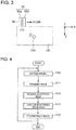
- FIG. 3 is a diagram illustrating an example of a method for using the probe illustrated in FIG. 2 .
- the mammography apparatus 1 includes a probe 36 and a detector 20.
- the probe 36 is a sensor element measuring internal information of the target object 10, and is formed of a pair of a transmitting antenna element 36a and a receiving antenna element 36b as illustrated in FIG. 2 .
- the transmitting antenna element 36a and the receiving antenna element 36b may be respective antenna arrays having a plurality of transmitting points and receiving points.
- the probe 36 has a configuration in which the transmitting antenna element 36a and the receiving antenna element 36b are joined together through a wave absorbing portion (electric wave absorbing portion) 38.
- the transmitting antenna element 36a and the receiving antenna element 36b are respectively connected to coaxial cables 34a and 34b.
- the wave absorbing portion is a portion absorbing a wave received by the transmitting antenna element 36a, and is an electric wave absorbing portion in a case where a wave is an electric wave such as a microwave.
- a description will be made of an example in which the wave absorbing portion is an electric wave absorbing portion, but the present invention is not limited to this example.
- Relative positions between the transmitting antenna element 36a and the receiving antenna element 36b are fixed in the probe 36.
- a configuration of the probe 36 is not limited to this configuration.
- the transmitting antenna element 36a and the receiving antenna element 36b are integrally provided through the electric wave absorbing portion 38.
- the receiving antenna element 36b and the transmitting antenna element 36a are integrally provided, and the electric wave absorbing portion 38 is located between the receiving antenna element 36b and the transmitting antenna element 36a.
- the phrase "integrally provided” indicates a state in which the transmitting antenna element 36a and the receiving antenna element 36b are provided in the probe 36, and the transmitting antenna element 36a and the receiving antenna element 36b are moved together.
- a case where the transmitting antenna element 36a and the receiving antenna element 36b are integrally provided includes not only a case where the transmitting antenna element 36a and the receiving antenna element 36b are disposed to be close to each other through the electric wave absorbing portion 38 but also a case where there are gaps between the antenna elements and the electric wave absorbing portion 38.
- the case where there are gaps between the antenna elements and the electric wave absorbing portion 38 is a case where the electric wave absorbing portion is disposed in a state in which there is a gap at least one of between the transmitting antenna element 36a and the electric wave absorbing portion 38 and between the receiving antenna element 36b and the electric wave absorbing portion 38.
- the electric wave absorbing portion 38 may employ an electric wave absorber (wave absorber) disposed between the transmitting antenna element 36a and the receiving antenna element 36b.
- the phrase "through the electric wave absorbing portion 38" also includes a case where an electric wave absorbing material (wave absorbing material) is attached to one surface of the transmitting antenna element 36a directed toward the receiving antenna element 36b or one surface of the receiving antenna element 36b directed toward the transmitting antenna element 36a in a film form according to a method such as coating, or a case where a tabular component made of the electric wave absorbing material is adhered and fixed onto the surface.
- the electric wave absorbing portion 38 may reduce the magnitude of a microwave (wave) which is directly received by the receiving antenna element 36b among microwaves (waves) transmitted from the transmitting antenna element 36a.
- the electric wave absorbing material is a conductive material, and is, specifically, metal, carbon, or the like.
- a code generated by a code generator 32a propagates to the transmitting antenna element 36a through the coaxial cable 34a.
- a signal received by the antenna element 36b propagates to a receiver circuit 32b through the coaxial cable 34b. Consequently, the receiver circuit 32b detects the received signal.
- the probe 36 measures internal information of the target object 10 while being moved on the target object 10 in response to an instruction (operation) from a user.
- the probe 36 is configured to be freely moved with respect to the target object 10.
- the transmitting antenna element 36a transmits a wave toward the target object 10, and the receiving antenna element 36b receives a scattered wave which is scattered at a scatterer 10a inside the target object 10.
- a microwave is described as an example of a wave, but a wave is not limited to a microwave, and an electric wave or an ultrasonic wave with other bandwidths may be used.
- the detector 20 includes a control device 30, an image reconstruction unit 40, the code generator 32a, and the receiver circuit 32b.
- the control device 30 controls transmission of a wave to the target object 10 from the code generator 32a, reception of a scattered wave in the receiver circuit 32b, and analysis of a received scattered wave in the image reconstruction unit 40.
- the control device 30 causes a trigger signal to propagate to the code generator 32a.
- the mammography apparatus 1 transmits a wave to the target object from the transmitting antenna element 36a, receives a scattered wave from the scatterer 10a with the receiving antenna element 36b, and analyzes the scattered wave with the image reconstruction unit 40 so as to generate an image.
- the code generator 32a generates a wave radiated from the transmitting antenna element 34a as a code on the basis of a trigger signal from the control device 30, and carries the code to the transmitting antenna element 34a.
- the code generator 32a generates, as a code, for example, a transmission timing of a wave radiated from the transmitting antenna element 36a, the number of times thereof, and a transmission gain.
- a wave radiated to the target object 10 from the transmitting antenna element 36a is, for example, a microwave.
- the receiver circuit 32b carries data regarding a scattered wave of the microwave received by the receiving antenna element 36b, to the image reconstruction unit 40.
- the data regarding the received scattered wave may be amplified by the receiver circuit 32b or may undergo signal processing such as AD conversion in the control device 30.
- the image reconstruction unit 40 analyzes the data regarding the scattered wave carried from the receiver circuit 32b, and images the data regarding the scattered wave according to an image reconstruction algorithm which will be described later. Consequently, a video corresponding to internal information of the target object 10 is reproduced on an image display 50.
- the image display 50 is a monitor screen, and outputs data calculated by the image reconstruction unit 40 as a video.
- an analysis model having a conical shape or a substantially conical shape may be supposed.
- a conical analysis model of which a diameter of the circle of the base is 30 cm is supposed.
- the probe 36 may be moved linearly along a generating line directed toward the base from the vertex of the cone.
- the transmitting antenna element 36a and the receiving antenna element 36b may be moved linearly in the same direction as an axis of rotation symmetry of the cone when seen in a plan view from at least one direction.
- the axis of rotation symmetry of the cone indicates a straight line connecting the vertex of the cone to the center of the base of the cone.
- the transmitting antenna element 36a and the receiving antenna element 36b are moved in a pair.
- FIG. 4 is a flowchart illustrating an operation of the mammography apparatus 1 according to the present embodiment illustrated in FIG. 1 .
- the a method of imaging internal information of internal information of the breast which is the target object 10 in the mammography apparatus 1 is as follows.
- the probe 36 is disposed on the target object 10 (S10) .
- a wave is radiated toward the target object 10 from the transmitting antenna element 36a (S11).
- a microwave is used as the wave.
- a wavelength, amplitude, and the like of the microwave are adjusted in the code generator 32a, and the microwave is radiated to the target object 10 from the transmitting antenna element 36a.
- scattered waves scattered waves reflected at normal tissue and cancer tissue of the inside of the target object 10 are received by the receiving antenna element 36b (S12).
- the normal tissue and the cancer tissue correspond to the scatterer 10a illustrated in FIG. 3 .
- a wave is an electromagnetic wave such as a microwave
- permittivity differs between the normal tissue and the cancer tissue, and thus intensities of scattered waves are different from each other.
- the received scattered wave may be amplified in the receiver circuit 32b, or may be converted to have a format appropriate for analysis in the image reconstruction unit 40 through, for example, AD conversion.
- scattered wave data indicating the received scattered wave is carried from the receiver circuit 32b to the image reconstruction unit 40.
- the image reconstruction unit 40 analyzes the carried scattered wave data (S13).
- the scattered wave data is analyzed according to the image reconstruction algorithm described below.
- an imaging function is derived. Consequently, videos (images) corresponding to the normal tissue and the cancer tissue of the inside of the target object 10 are reconstructed (S14) .
- the probe 36 is moved to be disposed at another observation position on the target object 10 (S10), and the above-described procedures are repeatedly performed.
- Data obtained through reconstruction using the imaging function is not required to be a moving image, and may be an image, that is, a still image.
- Data regarding a reconstructed video is carried from the image reconstruction unit 40 to the monitor 50, and is displayed on the monitor 50. Consequently, it is possible to recognize the presence, a position, a shape, and a size of the cancer tissue of the inside of the target object 10.
- the image reconstruction unit 40 reconstructs an image regarding internal information of the target object 10 on the basis of the scattered wave data indicating the scattered wave received by the receiving antenna element 36b. Specifically, the image reconstruction unit 40 derives a reconstruction function by solving a partial differential equation by using the scattered wave data and an analysis model indicating a shape. An image regarding internal information of the target object 10 is reconstructed by using the reconstruction function.
- the partial differential equation is an equation satisfied by the reconstruction function for reconstructing an image regarding internal information of the target object.
- the partial differential equation is an equation expressed by using independent variables indicating positions of transmitting points and receiving points inside the target object.
- the partial differential equation is a linear partial differential equation having, as a solution, a scattering field function which is a function of a field where a scattered wave is generated at each point in a space having the same order as the number of independent variables.
- the image reconstruction unit derives an imaging function which is a limiting value of a time variable of the reconstruction function, and reconstructs an image regarding internal information of the target object by using the imaging function.
- the image reconstruction algorithm corresponds to an image reconstruction principle of the mammography apparatus 1 which uses a pyramid having a linear generating line as an analysis model according to the present embodiment.
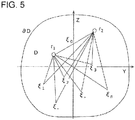
- FIGS. 5 to 7 illustrate analysis models for explaining a principle of a scattering tomography method according to the present embodiment.
- an imaging target is a cone having a linear generating line.
- a radiation point (transmitting antenna element 36a) and a receiving point (receiving antenna element 36b) of a wave are provided at any positions on the generating line.
- an analysis model is formed such that the probe 36 is moved on the generating line of the cone.
- monostatic analysis in which the radiation point and the receiving point are assumed to be located at the same position is performed.
- Internal information of an imaging target is imaged by using transmission data indicating a radiated wave which is radiated from the radiation point and scattered wave data indicating a scattered wave received at the receiving point.
- a Green's function reconstruction function which is necessary for imaging is set.
- a partial differential equation regarding a three-dimensional space formed of four variables such as (t,x,y,z) of which the function is a solution (function) is built.
- the partial differential equation is solved by using transmission data radiated from the transmitting antenna element 36a and reception data (scattering data) received by the receiving antenna element 36b as boundary conditions. Consequently, the imaging function is obtained, and internal information of an object can be imaged with high quality and at a high speed.
- FIG. 5 a situation is considered in which a wave emitted from a point r 1 is reflected at a point ⁇ so as to be returned to a point r 2 .
- the point r 1 and the point r 2 are located at the same position.
- the transmitting point r 1 and the receiving point r 2 of a wave are freely moved inside an x section D (a side surface of a cone 60a).
- G r 1 , r 2 , ⁇
- this function relates to a distribution of reflection points in a region.
- ⁇ is an angular frequency
- ⁇ 2 ⁇ f.
- G(r 1 ,r 2 , ⁇ ) is a sum of reflected signals from all points ⁇ , and, since there are many reflection points in the region, and G(r 1 ,r 2 , ⁇ ) may be written as in the following Equation (1).
- Equation (1) Equation (1).
- ⁇ r 1 ⁇ ⁇ ⁇ r 2 , ⁇ indicates a signal intensity of a wave which is emitted from the point r 1 , and is reflected at the point ⁇ so as to be returned to the point r 2 .
- the parameters r 1 and r 2 in the expression are vectors, and are boldface in the expression.
- coordinates of the transmitting point r 1 and the receiving point r 2 of a wave are the same as each other at all times.
- Equation (2) A partial region of a three-dimensional space is indicated by D, and a boundary thereof is indicated by ⁇ D.
- G (r, t ) is a function obtained by performing Fourier transform on G(r, ⁇ ) with respect to ⁇ .
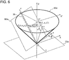
- FIGS. 6 and 7 illustrate analysis models for explaining a method of obtaining the differential operators.
- an imaging target is assumed to be the cone 60a having a linear generating line.
- the probe 36 is moved linearly along the generating line of the cone 60a.
- the probe 36 may be rotationally moved centering on an axis passing through the vertex of the cone 60a and the center of the base of the cone 60a.
- measurement is performed while the transmitting antenna element 36a and the receiving antenna element 36b are being moved linearly in the same direction as an axis of rotational symmetry of the cone 60a used as the analysis model when seen in a plan view from at least one direction.
- the axis of rotational symmetry of the cone indicates a straight line connecting the vertex of the cone to the center of the base of the cone.
- the vertex of the cone 60a is indicated by a point O
- the center of the circle of the base of the cone 60a is indicated by a point O'
- a direction directed from the point O to the point O' is set to a Z direction (Z axis direction).
- a plane which passes through the point O and is parallel to the base of the cone 60a is set to a reference plane 70a. Any one direction in the reference plane 70a is set to an X direction (X axis direction), and a direction perpendicular to the X direction in the reference plane 70a is set to a Y direction (Y axis direction).
- a direction which is parallel to the X direction is set to an X' direction (X' axis direction), and a direction which is parallel to the Y axis direction is set to a Y' direction (Y' axis direction).
- a plane which is in contact with the cone 60a at a position of the probe 36 is set to the tangential plane 80a.
- One direction of an intersection line at which the tangential plane 80a intersects the reference plane 70a is set to an x direction (x axis direction).
- a direction directed from the point O toward the base of the cone 60a is set to a y direction (y axis direction) .
- a direction perpendicular to the x direction and the y direction is set to a z direction (z axis direction).
- FIG. 7 is a partially enlarged schematic diagram of a locus of the probe 36 moved on the generating line of the cone 60a illustrated in FIG. 6 .
- the measurement points P 1 and P 2 are assumed to be moved on any straight line where the linear array antenna 36 is disposed.
- Equation (4) a function ⁇ as in the following Equation (4) is introduced.
- c is a propagation velocity
- k is a wave number
- ⁇ in Equation (4) corresponds to a reconstruction function (solution) for reconstructing an image regarding internal information of an object in the present invention.
- ⁇ , ⁇ , and ⁇ are respectively an x coordinate, a y coordinate, and a z coordinate of the point P( ⁇ , ⁇ , ⁇ ) illustrated in FIGS. 6 and 7 .
- the point P( ⁇ , ⁇ , ⁇ ) is any scattering point in the region.
- a partial differential equation having this equation and results of differentiation and integration of the equation with respect to ⁇ , ⁇ , and ⁇ as solutions is obtained. To do so, high order terms related to 1/p generated as a result of differentiation may be disregarded, and calculation may be performed.
- shortcuts in differentiation are defined as in the following Expression (5).
- Equation (8) is derived assuming a steady state, but is easily expanded to a case of a non-steady state.
- Equation (8) is performed on Equation (8) .
- Equation (8) [Math. 25] ⁇ ik ⁇ 1 c ⁇ t
- Equation (10) corresponds to a partial differential equation in the present invention.
- Equation (10) corresponds to a partial differential equation in the present invention.
- Equation (10) is applied to the integral kernel, and thus ⁇ also satisfies the partial differential equation.
- the equation is a three-dimensional pseudo wave equation formed of four variables including t, x, y, and z.
- Equation (10) is solved by using Fourier transform.
- Equation (11) is obtained.
- Equation (11) is obtained.
- Equation (12) e iz 4 k 2 ⁇ k x 2 ⁇ k y 2
- E 2 e ⁇ iz 4 k 2 ⁇ k x 2 ⁇ k y 2
- Equation (20) In order to perform integration with respect to k, variable transformation is performed according to the following Equation (20) .
- Equation (21) an imaging function ⁇ (r, ⁇ ) in a local coordinate system at the angle ⁇ is obtained.
- Equation (22) A result obtained at each angle ⁇ is integrated, and thus a three-dimensional reconstructed image shown in Equation (22) is obtained.
- P X , Y , Z ⁇ 0 2 ⁇ ⁇ x , y , z , ⁇ d ⁇
- variable transformation is performed according to the following Equation (27).
- Equations (27) and (28) are not the coordinate ( ⁇ , ⁇ , ⁇ ) of the point P used in FIG. 7 , Equation (22) and the like, and are new variables for variable transformation.
- k x , k y , k z , and the like are functions of ⁇ , ⁇ , and ⁇ as in Equations (26) and (28), and thus data in local coordinates of the angle ⁇ can be transformed into the whole coordinates by using only Fourier transform.
- Equation (30) a reconstructed image, that is, an imaging function as shown in Equation (30) is obtained through integration with respect to the angle ⁇ .
- the mammography apparatus 1 according to the present embodiment is effective in observation of defective tissue in, especially, the breast.
- observation using an X-ray has a problem that the type of organic tissue is hard to identify by using an X-ray, and thus the X-ray is not suitable for observation of defective tissue in the breast.
- Observation using an ultrasonic wave has a problem that an ultrasonic wave is greatly attenuated in the lipid occupying the large part of a region, thus it is hard to improve S/N of a constructed image, and therefore the ultrasonic wave is not suitable for observation of defective tissue in the breast.
- Observation using MRI has a problem that a contrast agent is necessary, a clear constructed image is obtained, but defective tissue is hard to identify from the constructed image, and thus MRI is not suitable for observation of defective tissue in the breast.
- a superconducting coil and a cooling system thereof which are required to generate a strong magnetic field are large-sized, and expensive.
- an ultra-wideband (UWB) microwave with 1 to 10 GHz is used for observation in the mammography apparatus 1 according to the present embodiment.
- a microwave is scarcely attenuated in a living body, particularly, the lipid and the like, and thus the microwave is effective in observation of defective tissue in the breast.
- An apparatus configuration is simpler than MRI, other substances such as a contrast agent is not necessary, and thus the mammography apparatus can be versatilely used.
- the mammography apparatus 1 images a three-dimensional constituent element of the inside of a living body such as the breast on the basis of multi-path (multistatic) scattered wave data of a microwave by using the above-described reverse scattering theory, and thus it is possible to image internal information (configuration) of the living body versatilely and at a high speed.
- FIG. 8 is a schematic diagram illustrating a test model for a measurement test using the mammography apparatus 1 according to Embodiment 1.
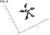
- FIG. 9 is a diagram illustrating a measurement result of measuring the test model illustrated in FIG. 8 in the mammography apparatus.
- the breast of a pig is supposed as a test model 100, as illustrated in FIGS. 8(a) and 8(b) , alumina balls 100b each of which has a diameter of 1 mm and relative permittivity of 6 fill a plastic container 100a of which an inner diameter is 30 cm, and a height is about 10 cm, and five rubber hoses 100c containing water and each having a section diameter of 5 mm are disposed to be buried in the alumina balls 100b.
- a microwave with 10 GHz or less was used as a microwave transmitted from the transmitting antenna.
- an antenna of which a size of a portion brought into contact with the test model 100 is about 15 mm x 15 mm was as each of the transmitting antenna 36a and the receiving antenna 36b.
- the test model 100 was observed by the mammography apparatus 1 according to the present embodiment, and, as illustrated in FIG. 9 , the five rubber hoses 100c containing water disposed in the test model 100 could be observed.
- the observation could be performed while changing an observation position in the depth direction by changing a frequency of the microwave. In the observation result illustrated in FIG.
- the mammography apparatus 1 according to the present embodiment is effective, especially, in observation of defective tissue in the breast.
- the mammography apparatus 1 of the present embodiment in the analysis model in which the probe 36 is moved linearly along the generating line of the cone 60a, a partial differential equation for inverse problem is set, and an imaging function is obtained by solving the equation. Consequently, in the mammography apparatus 1 according to the present embodiment, it is possible to image internal information of the target object 10 versatilely and at a high speed.
- the mammography apparatus 1 uses a microwave as a wave, and thus there is no probability of exposure to radiation when an X-ray is radiated to a living body and is safe, compared with an observation method using an X-ray. Since a contrast ratio between cancer tissue and normal tissue is high in an image, it is possible to perform observation with high sensitivity in a short period of time, compared with an observation method using an X-ray. Since observation can be performed in a state in which the probe is brought into contact with an examination target location, it is possible to achieve miniaturization and low cost of an apparatus.
- image analysis can be performed without depending on subjectivity or a skill of a user, that is, a diagnostician such as a doctor, it is possible to perform accurate diagnosis even in a case where a diagnostician differs.
- observation can be performed in a state in which the probe is brought into contact with an examination target location without pressing the examination target location, it is possible to easily perform observation in a state in which a patient does not feel pain with clothes.
- calculation formulae and the procedures of deriving the calculation formulae are only examples, and other calculation formulae and other deriving procedures may be used.
- a microwave is used as a wave, but a wave is not limited to a microwave, and may be an electromagnetic wave with frequencies in other frequency range, and may be an ultrasonic wave.
- a microwave since a microwave is used, a periodic wave with a predetermined frequency is used, but a wave is not limited to a periodic wave, and a pulse wave may be used.
- the breast has been described as an example of a target object, but a target object is not limited to the breast, and may be other living bodies or objects, for example, a conical concrete support.
- a configuration of a mammography apparatus 1 according to the present embodiment is substantially the same as the configuration of the mammography apparatus 1 according to Embodiment 1, but is different from the mammography apparatus 1 according to Embodiment 1 in that a generating line of a cone in the analysis model of the cone described in Embodiment 1 is curved, and the transmitting antenna element 36a and the receiving antenna element 36b are moved along the curved generating line. Therefore, an image reconstruction algorithm executed in an image reconstruction unit of the mammography apparatus 1 according to the present embodiment is different from that in the mammography apparatus 1 according to Embodiment 1.
- the transmitting antenna element 36a and the receiving antenna element 36b are integrally moved along a line corresponding to a curved generating line of a substantial cone in the target object 10.
- the "substantial cone” is a cone having a curved generating line
- the "line corresponding to the generating line of the substantial cone” is a line corresponding to a curved generating line of a substantial cone in a case where a shape of a target object 10 is regarded as a substantially conical shape having a curved generating line.
- FIGS. 10 and 11 illustrate analysis models for explaining a principle of a scattering tomography method according to the present embodiment.
- a description will be made of derivation of an imaging function in the mammography apparatus according to the present embodiment by using a model illustrated in FIGS. 10 and 11 as an analysis model.
- an imaging target (target object 10) is a cone having a curved generating line, that is, a hemispherical or a dome-like cone.
- a radiation point (single transmitting antenna element 36a) and a receiving point (single receiving antenna element 36b) of a wave are provided at any positions on the generating line.
- an analysis model is formed such that the probe 36 is moved on the generating line of the cone having the curved generating line.
- monostatic analysis in which the radiation point and the receiving point are assumed to be located at the same position is performed. Internal information of an imaging target is imaged by using transmission data indicating a radiated wave which is radiated from the radiation point and scattered wave data indicating a scattered wave received at the receiving point.
- an imaging target is assumed to be a cone (substantial cone) 60b having a curved generating line.
- the probe 36 is moved along the generating line of the cone 60b.
- the probe 36 may be rotationally moved centering on an axis passing through the vertex of the cone 60b and the center of the base of the cone 60b.
- measurement is performed while the probe 36 formed of a plurality of transmitting antenna elements 36a and a plurality of receiving antenna elements 36b are being moved linearly in the same direction as an axis of rotational symmetry of the cone 60b used as the analysis model when seen in a plan view from at least one direction.
- the axis of rotational symmetry of the cone indicates a straight line connecting the vertex of the cone to the center of the base of the cone.
- a tangential plane 80b of the cone 60b at a position of the probe 36 is supposed, the virtual tangential plane 80b is rotated centering on the axis passing through the vertex of the cone 60b and the center of the base of the cone 60b, and scattered wave data is obtained with respect to all rotation angles ⁇ .
- a three-dimensional internal structure of the cone 60b is reconstructed on the basis of monostatic time series data in the surface of the cone 60b. A theory thereof will now be described.
- the vertex of the cone 60b is indicated by a point O
- the center of the circle of the base of the cone 60b is indicated by a point O'.
- a direction directed from the point O to the point O' is set to a Z direction (Z axis direction).
- a plane which is in contact with the cone 60b at a position of the probe 36 is set to the tangential plane 80b.
- a plane which includes a point at which the tangential plane 80b intersects the Z axis and is parallel to the base of the cone 60b is set to a reference plane 70b. Any one direction in the reference plane 70b is set to an X direction (X axis direction), and a direction perpendicular to the X direction in the reference plane 70b is set to a Y direction (Y axis direction).
- a direction which is parallel to the X direction is set to an X' direction (X' axis direction), and a direction which is parallel to the Y axis direction is set to a Y' direction (Y' axis direction).
- One direction of an intersection line at which the tangential plane 80b intersects the reference plane 70b is set to an x direction (x axis direction).
- a direction directed from the point O toward the base of the cone 60b is set to a y direction (y axis direction).
- a direction perpendicular to the x direction and the y direction is set to a z direction (z axis direction).
- FIG. 11 is a partially enlarged schematic diagram of a locus of the probe 36 moved on the generating line of the cone 60b illustrated in FIG. 10 .
- x and y coordinates are located on a surface of the target object, and a z coordinate is located in a normal direction to the surface of the target object.
- the probe 36 is moved to be curved on a curved surface in the xyz space.
- a Green's function reconstruction function which is necessary for imaging is set.
- a partial differential equation regarding a three-dimensional space formed of four variables such as (t,x,y,z) of which the function is a solution (function) is built.
- the partial differential equation is solved by using transmission data radiated from the transmitting antenna element 36a and reception data (scattering data) received by the receiving antenna element 36b as boundary conditions and the strict imaging function is obtained. Consequently, internal information of an object can be imaged with high quality and at a high speed.
- FIG. 10 a situation is considered in which a wave emitted from a point r 1 is reflected at a point ⁇ so as to be returned to a point r 2 .
- the point r 1 and the point r 2 are located at the same position.
- the transmitting point r 1 and the receiving point r 2 of a wave are freely moved on the curved surface (a side surface of a cone 60b) while satisfying a certain constraint condition. If data obtained in this case is indicated by G(r 1 ,r 2 , ⁇ ), this function relates to a distribution of reflection points in a region.
- ⁇ is an angular frequency, and is 2 ⁇ f.
- G(r 1 ,r 2 , ⁇ ) is a sum of reflected signals from all points ⁇ , and, since there are many reflection points in the region, and G(r 1 ,r 2 , ⁇ ) may be regarded in the same manner as in Equation (1) described in Embodiment 1.
- the constraint condition imposed on the transmitting point r 1 and the receiving point r 2 of a wave is a condition that the point r 1 and the point r 2 are moved on a certain curved surface, and the point r 1 and the point r 2 are located at the substantially same position (coordinate).
- the generating line of the cone in the analysis model of Embodiment 1 is curved, and the transmitting antenna and the receiving antenna are moved along the curved generating line.
- the antenna array may be rotationally moved centering on the Z axis.
- a function ⁇ as in the following Equation (31) is introduced.
- ⁇ in Equation (34) corresponds to a reconstruction function (solution) for reconstructing an image regarding internal information of an object in the present invention.
- a partial differential equation having this equation and results of differentiation and integration of the equation with respect to ⁇ , ⁇ , and ⁇ as solutions is obtained. To do so, high order terms related to 1/p generated as a result of differentiation may be disregarded, and calculation may be performed.
- shortcuts in differentiation are defined as in the following Expression (33).
- Equation (37) corresponds to a partial differential equation in the present invention.
- Equation (37) corresponds to a partial differential equation in the present invention.
- Equation (37) A solution of Equation (37) is obtained by assuming that a time factor of ⁇ is proportional to exp -i ⁇ t .
- Equation (38) the following Equation (38) is obtained.
- Equation (37) may be rewritten as in the following Equation (41) through inverse Fourier transform.
- Equation (44) is given as follows. [Math. 65]
- Equation (47) k x is not included in the right side of Equation (47).
- Equation (48) Equation (48) by taking into consideration that data about a certain angle ⁇ is obtained.
- Equation (49) is rewritten as the following Equation (50). [Math. 68]
- Equation (53) a (k x ,k y ,k) is obtained as in the following Equation (53).
- Equation (60) is rewritten as the following Equation (61).
- variable transformation In a spectral region, variable transformation (inverse transformation) is performed according to the following Equation (62).
- Equation (62) and (63) are not the coordinate ( ⁇ , ⁇ , ⁇ ) of the point P used in FIG. 10 , Equation (31) and the like, and are new variables for variable transformation.
- Equation (64) A reconstruction function at the angle ⁇ is obtained as in the following Equation (64).
- Equation (28) data in local coordinates of the angle ⁇ can be transformed into the whole coordinates by using only Fourier transform.
- Equation (66) is used for transform into the whole coordinates. That is, finally, an imaging function is obtained through integration with respect to the angle ⁇ .
- An image regarding internal information of the target object 10 is reconstructed by using the imaging function. Therefore, it is possible to generate an image regarding internal information of the target object 10 such as an internal defect and the like of the target object 10 versatilely and at a high speed.
- the function ⁇ is set in a three-dimensional space, and thus it is possible to image internal information of the target object 10 having a curved surface with a large curvature with higher accuracy and at a high speed.
- a partial differential equation for inverse problem is set in an analysis model in which the probe 36 is moved to be curved on a curved surface, and an imaging function is obtained by solving the equation. Consequently, in the mammography apparatus analyzing a scattered wave of a wave radiated to a living body which is a target object, it is possible to image internal information of a target object having a curved surface with a large curvature versatilely and at a high speed.
- a mammography apparatus is different from the mammography apparatus 1 according to Embodiment 1 in that a target obj ect having an asymmetric conical shape is used as an analysis model.
- the transmitting antenna element 36a and the receiving antenna element 36b are integrally moved along a line corresponding to a generating line of an asymmetric pyramid in the target object 10.
- the "line corresponding to the generating line of the asymmetric pyramid” is a line corresponding to a generating line of a pyramid in a case where a shape of a target object 10 is regarded as an asymmetric pyramidal shape.
- a shape of the living body partially matches a shape of a cone or a shape of a substantial cone having a rotationally symmetric shape, such as the analysis models described in Embodiments 1 and 2, but may not completely match these shapes.
- an analysis model in the mammography apparatus 1 according to the present embodiment may be used.
- FIG. 12 illustrates an analysis model for explaining a principle of a scattering tomography method according to the present embodiment.
- An image reconstruction algorithm of the mammography apparatus is substantially the same as the image reconstruction algorithm of the mammography apparatus according to Embodiment 1, but is different from that of the mammography apparatus 1 according to Embodiment 1 in that the angle ⁇ in the analysis model illustrated in FIG. 2 depends on the rotation angle ⁇ of the generating line.
- the target object 10 has a rotationally asymmetric pyramidal shape, and also has a shape of which a part is omitted.
- Equation (67) a variable transform formula used for variable transformation in the spectral region and an inverse transform formula thereof are expressed in the following Equation (67).
- Equation (68) A reconstruction function at the angle ⁇ is obtained as in the following Equation (68).
- Equation (69) a reconstructed image shown in Equation (69) is obtained through integration using the angle ⁇ .
- a partial differential equation for inverse problem is set, and an imaging function can be obtained by solving the equation. Consequently, in the mammography apparatus analyzing a scattered wave of a wave radiated to an object, even in a case where a target object is flexible or is not a perfect cone or a substantial cone, it is possible to image internal information of the target object versatilely and at a high speed.
- the analysis model obtained by omitting a part of the analysis model of the pyramid described in Embodiment 1 has been described as an example, but an analysis model by omitting a part of the analysis model of the pyramid described in Embodiment 2 may be used.
- an imaging function can be obtained by changing a variable transform formulae used for variable transformation in the spectral region and an inverse transform formula thereof with respect to the equations in the same manner as in the image reconstruction algorithm in the analysis model of the mammography apparatus according to the present embodiment.
- the examination apparatus and the examination method according to the present invention have been described on the basis of a plurality of embodiments by exemplifying mammography, but the present invention is not limited to the embodiments.
- the present invention also includes a form obtained by applying modifications of which a person skilled in the art conceives to the embodiments, and other forms realized by combining any constituent elements in the plurality of embodiments with each other.
- the mammography has been described as an example, and thus a living body, specifically, the breast has been described as an example of a target object, but a target object is not limited to the breast, and may be structures of other living bodies.
- a target object is not limited to a living body, and may be structures of objects other than a living body.
- a target object may be a structure such as a conical concrete support.
- an analysis model appropriate for a shape of a target object may be built as appropriate.
- a microwave was used as a wave, but a wave is not limited to a microwave, and electromagnetic waves with frequencies in other frequency range or an ultrasonic wave.
- a microwave since a microwave is used, a periodic wave with a predetermined frequency is used, but a wave is not limited to a periodic wave, and a pulse wave may be used.
- calculation formulae and the procedures of deriving the calculation formulae are only examples, and other calculation formulae and other deriving procedures may be used.
- a specific processing unit may perform a process performed by another processing unit.
- an order of performing processes may be changed, and a plurality of processes may be performed in parallel.
- a step of observing internal information of a target object in the examination apparatus of the present invention may be executed by a computer.
- the present invention can be realized as a program for causing a computer to execute steps included in the scattering tomography method.
- the present invention can be realized as a non-transitory computer readable recording medium such as a CD-ROM on which the program is recorded.
- a plurality of constituent elements included in the examination apparatus may be realized as an LSI which is an integrated circuit.
- the constituent elements may be separately formed as one chip, and some or all thereof may be included in one chip.
- an LSI is mentioned, but may be called an integrated circuit (IC), a system LSI, a super LSI, or an ultra LSI depending on a difference in the degree of integration.
- a technique for an integrated circuit is not limited to an LSI, and may be realized by a dedicated circuit or a general purpose processor.
- a field programmable gate array (FPGA) which is programmable or a reconfigurable processor in which connection and setting of circuit cells of the LSI inside can be reconstruct may be used.
- the constituent elements included in the mammography apparatus may be naturally formed as integrated circuits by using the technique.
- the examination apparatus and the examination method according to the present invention are useful for examination of a target object having a flexible shape, and are applicable to, for example, a medical apparatus such as a mammography apparatus.
Landscapes
- Health & Medical Sciences (AREA)
- Engineering & Computer Science (AREA)
- Life Sciences & Earth Sciences (AREA)
- Physics & Mathematics (AREA)
- General Physics & Mathematics (AREA)
- General Health & Medical Sciences (AREA)
- Pathology (AREA)
- Medical Informatics (AREA)
- Theoretical Computer Science (AREA)
- Veterinary Medicine (AREA)
- Biomedical Technology (AREA)
- Heart & Thoracic Surgery (AREA)
- Radiology & Medical Imaging (AREA)
- Molecular Biology (AREA)
- Surgery (AREA)
- Animal Behavior & Ethology (AREA)
- Nuclear Medicine, Radiotherapy & Molecular Imaging (AREA)
- Public Health (AREA)
- Biophysics (AREA)
- Biochemistry (AREA)
- Chemical & Material Sciences (AREA)
- Analytical Chemistry (AREA)
- Electromagnetism (AREA)
- Immunology (AREA)
- High Energy & Nuclear Physics (AREA)
- Multimedia (AREA)
- Signal Processing (AREA)
- Pulmonology (AREA)
- Computer Vision & Pattern Recognition (AREA)
- Optics & Photonics (AREA)
- Radar Systems Or Details Thereof (AREA)
- Analysing Materials By The Use Of Radiation (AREA)
- Apparatus For Radiation Diagnosis (AREA)
- Studio Devices (AREA)
- Air Bags (AREA)
- Investigating Or Analyzing Materials By The Use Of Ultrasonic Waves (AREA)
Priority Applications (1)
| Application Number | Priority Date | Filing Date | Title |
|---|---|---|---|
| PL16851695T PL3358338T3 (pl) | 2015-09-29 | 2016-09-28 | Sposób obrazowania i aparat obrazujący |
Applications Claiming Priority (2)
| Application Number | Priority Date | Filing Date | Title |
|---|---|---|---|
| JP2015192216 | 2015-09-29 | ||
| PCT/JP2016/078742 WO2017057524A1 (fr) | 2015-09-29 | 2016-09-28 | Procédé et appareil de formation d'image |
Publications (3)
| Publication Number | Publication Date |
|---|---|
| EP3358338A1 true EP3358338A1 (fr) | 2018-08-08 |
| EP3358338A4 EP3358338A4 (fr) | 2019-06-12 |
| EP3358338B1 EP3358338B1 (fr) | 2022-03-30 |
Family
ID=58427491
Family Applications (1)
| Application Number | Title | Priority Date | Filing Date |
|---|---|---|---|
| EP16851695.3A Active EP3358338B1 (fr) | 2015-09-29 | 2016-09-28 | Procédé et appareil de formation d'image |
Country Status (10)
| Country | Link |
|---|---|
| US (1) | US10586354B2 (fr) |
| EP (1) | EP3358338B1 (fr) |
| JP (1) | JP6752473B2 (fr) |
| CN (1) | CN108139340B (fr) |
| DK (1) | DK3358338T3 (fr) |
| ES (1) | ES2918590T3 (fr) |
| HU (1) | HUE059413T2 (fr) |
| PL (1) | PL3358338T3 (fr) |
| PT (1) | PT3358338T (fr) |
| WO (1) | WO2017057524A1 (fr) |
Cited By (2)
| Publication number | Priority date | Publication date | Assignee | Title |
|---|---|---|---|---|
| EP3634237A4 (fr) * | 2017-06-08 | 2021-03-10 | Emvision Medical Devices Ltd | Système et procédé d'imagerie tomographique |
| WO2025054721A1 (fr) * | 2023-09-12 | 2025-03-20 | Wave View Imaging Inc. | Procédé et système de détermination de configuration de positionnement d'antennes utilisées dans le balayage de tissu biologique |
Families Citing this family (15)
| Publication number | Priority date | Publication date | Assignee | Title |
|---|---|---|---|---|
| JP6938812B2 (ja) * | 2017-02-24 | 2021-09-22 | 株式会社三井E&Sマシナリー | データ処理方法及び計測装置 |
| US11237103B2 (en) * | 2018-05-31 | 2022-02-01 | Socovar Sec | Electronic device testing system, electronic device production system including same and method of testing an electronic device |
| JP7147674B2 (ja) * | 2019-04-19 | 2022-10-05 | 凸版印刷株式会社 | 検査用シール |
| WO2020059861A1 (fr) | 2018-09-20 | 2020-03-26 | 凸版印刷株式会社 | Articulation de test |
| JP7107201B2 (ja) * | 2018-12-11 | 2022-07-27 | 凸版印刷株式会社 | 検査用シール |
| JP7351162B2 (ja) * | 2018-09-20 | 2023-09-27 | 凸版印刷株式会社 | 検査用シール |
| JP7107200B2 (ja) * | 2018-12-10 | 2022-07-27 | 凸版印刷株式会社 | 検査用シール |
| JP7183938B2 (ja) * | 2019-04-25 | 2022-12-06 | 凸版印刷株式会社 | 検査用シール |
| TWI872093B (zh) * | 2019-08-01 | 2025-02-11 | 日商積分幾何科學股份有限公司 | 散射斷層掃描裝置及散射斷層掃描方法 |
| EP4033228B1 (fr) * | 2019-09-17 | 2025-08-13 | Integral Geometry Science Inc. | Dispositif de tomographie par diffusion et procédé de tomographie par diffusion |
| JP7427943B2 (ja) * | 2019-12-06 | 2024-02-06 | Toppanホールディングス株式会社 | 補助シール、および、検査用シールセット |
| US11888233B2 (en) * | 2020-04-07 | 2024-01-30 | Ramot At Tel-Aviv University Ltd | Tailored terahertz radiation |
| WO2022260112A1 (fr) * | 2021-06-11 | 2022-12-15 | 株式会社 Integral Geometry Science | Dispositif d'imagerie et procédé d'imagerie |
| IL309050A (en) * | 2021-06-17 | 2024-02-01 | Kimura Kenjiro | Imaging device and imaging method |
| IL317178A (en) * | 2022-11-29 | 2025-01-01 | KIMURA Fumitoshi | Imaging device and imaging method |
Family Cites Families (16)
| Publication number | Priority date | Publication date | Assignee | Title |
|---|---|---|---|---|
| DE3224453A1 (de) * | 1982-06-30 | 1984-01-05 | Siemens AG, 1000 Berlin und 8000 München | Ultraschall-tomographiegeraet |
| DE3531893A1 (de) * | 1985-09-06 | 1987-03-19 | Siemens Ag | Verfahren zur bestimmung der verteilung der dielektrizitaetskonstanten in einem untersuchungskoerper sowie messanordnung zur durchfuehrung des verfahrens |
| US5363050A (en) * | 1990-08-31 | 1994-11-08 | Guo Wendy W | Quantitative dielectric imaging system |
| US5859609A (en) * | 1991-08-30 | 1999-01-12 | Battelle Memorial Institute | Real-time wideband cylindrical holographic surveillance system |
| US5588032A (en) * | 1992-10-14 | 1996-12-24 | Johnson; Steven A. | Apparatus and method for imaging with wavefields using inverse scattering techniques |
| US6876878B2 (en) | 1996-06-26 | 2005-04-05 | University Of Utah Research Foundation | Medical broad band electromagnetic holographic imaging |
| US7840249B2 (en) * | 2004-11-24 | 2010-11-23 | University Of Iowa Research Foundation | Clinical micro-CT (CMCT) methods, techniques and apparatus |
| EP2012139A1 (fr) * | 2007-07-06 | 2009-01-07 | Sensino Limited | Appareil et procédé de surveillance du corps |
| DE102009007255A1 (de) * | 2008-06-02 | 2009-12-03 | Rohde & Schwarz Gmbh & Co. Kg | Brustkrebserkennung mit Fixierungstrichter |
| JP5197461B2 (ja) * | 2009-03-27 | 2013-05-15 | 三井造船株式会社 | 対象物中の誘電率算出装置及び誘電率算出方法 |
| WO2010143691A1 (fr) * | 2009-06-10 | 2010-12-16 | 国立大学法人静岡大学 | Appareil de diagnostic |
| JP5638827B2 (ja) * | 2010-04-02 | 2014-12-10 | 古河電気工業株式会社 | 内蔵型レーダ用送受一体アンテナ |
| US9329263B2 (en) * | 2011-05-23 | 2016-05-03 | The Regents Of The University Of Michigan | Imaging system and method |
| WO2014125815A1 (fr) * | 2013-02-12 | 2014-08-21 | 国立大学法人神戸大学 | Procédé de tomographie à diffusion et dispositif de tomographie à diffusion |
| JP2014198067A (ja) * | 2013-03-29 | 2014-10-23 | 国立大学法人静岡大学 | 診断装置 |
| ES2796098T3 (es) * | 2014-03-12 | 2020-11-25 | Kenjiro Kimura | Método de tomografía de dispersión y dispositivo de tomografía de dispersión |
-
2016
- 2016-09-28 CN CN201680059162.XA patent/CN108139340B/zh active Active
- 2016-09-28 US US15/764,091 patent/US10586354B2/en active Active
- 2016-09-28 PL PL16851695T patent/PL3358338T3/pl unknown
- 2016-09-28 WO PCT/JP2016/078742 patent/WO2017057524A1/fr not_active Ceased
- 2016-09-28 ES ES16851695T patent/ES2918590T3/es active Active
- 2016-09-28 DK DK16851695.3T patent/DK3358338T3/da active
- 2016-09-28 EP EP16851695.3A patent/EP3358338B1/fr active Active
- 2016-09-28 HU HUE16851695A patent/HUE059413T2/hu unknown
- 2016-09-28 JP JP2017543529A patent/JP6752473B2/ja active Active
- 2016-09-28 PT PT168516953T patent/PT3358338T/pt unknown
Cited By (2)
| Publication number | Priority date | Publication date | Assignee | Title |
|---|---|---|---|---|
| EP3634237A4 (fr) * | 2017-06-08 | 2021-03-10 | Emvision Medical Devices Ltd | Système et procédé d'imagerie tomographique |
| WO2025054721A1 (fr) * | 2023-09-12 | 2025-03-20 | Wave View Imaging Inc. | Procédé et système de détermination de configuration de positionnement d'antennes utilisées dans le balayage de tissu biologique |
Also Published As
| Publication number | Publication date |
|---|---|
| DK3358338T3 (da) | 2022-06-20 |
| JP6752473B2 (ja) | 2020-09-09 |
| ES2918590T3 (es) | 2022-07-19 |
| JPWO2017057524A1 (ja) | 2018-08-02 |
| US20180308259A1 (en) | 2018-10-25 |
| HUE059413T2 (hu) | 2022-11-28 |
| PT3358338T (pt) | 2022-06-20 |
| CN108139340B (zh) | 2021-03-09 |
| EP3358338A4 (fr) | 2019-06-12 |
| EP3358338B1 (fr) | 2022-03-30 |
| CN108139340A (zh) | 2018-06-08 |
| PL3358338T3 (pl) | 2022-07-04 |
| US10586354B2 (en) | 2020-03-10 |
| WO2017057524A1 (fr) | 2017-04-06 |
Similar Documents
| Publication | Publication Date | Title |
|---|---|---|
| EP3358338B1 (fr) | Procédé et appareil de formation d'image | |
| EP3117777B1 (fr) | Procédé de tomographie par diffusion et dispositif de tomographie par diffusion | |
| EP2957925B1 (fr) | Procédé de tomographie à diffusion et dispositif de tomographie à diffusion | |
| Gemmeke et al. | 3D ultrasound computer tomography for medical imaging | |
| US9741111B2 (en) | Subject information acquiring device and subject information acquiring method | |
| KR101307514B1 (ko) | 마이크로파 영상 복원 장치 | |
| US11857305B2 (en) | System and method for detecting an assymetrically positioned internal object in a body | |
| US9519980B2 (en) | Object information acquiring apparatus | |
| WO2018127434A1 (fr) | Procédé et système pour assurer un contact d'antenne et une fonction système dans les applications de détection des propriétés diélectriques internes dans le corps | |
| US20160310092A1 (en) | Trabecular bone analyzer | |
| CN106896120A (zh) | 多模态检测系统和方法 | |
| Guardiola et al. | UWB high-contrast robust tomographic imaging for medical applications | |
| Goncharsky et al. | Artifacts of reconstructed images in inverse problems of ultrasound tomography in models with absorption | |
| JP6556300B2 (ja) | 被検体情報取得装置、被検体情報取得方法およびプログラム | |
| Zuo et al. | Rapid High-Resolution Breast Imaging With Ring-Array Multi-Subarray Synthetic-Aperture Frequency-Domain Ultrasound Computed Tomography Method | |
| Watanabe et al. | 2P5-3 Fundamental Study on Application of Ultrasonic Computed Tomography in Bone Existing Region | |
| Guardiola Garcia et al. | UWB High-contrast robust tomographic imaging for medical applications |
Legal Events
| Date | Code | Title | Description |
|---|---|---|---|
| STAA | Information on the status of an ep patent application or granted ep patent |
Free format text: STATUS: THE INTERNATIONAL PUBLICATION HAS BEEN MADE |
|
| PUAI | Public reference made under article 153(3) epc to a published international application that has entered the european phase |
Free format text: ORIGINAL CODE: 0009012 |
|
| STAA | Information on the status of an ep patent application or granted ep patent |
Free format text: STATUS: REQUEST FOR EXAMINATION WAS MADE |
|
| 17P | Request for examination filed |
Effective date: 20180329 |
|
| AK | Designated contracting states |
Kind code of ref document: A1 Designated state(s): AL AT BE BG CH CY CZ DE DK EE ES FI FR GB GR HR HU IE IS IT LI LT LU LV MC MK MT NL NO PL PT RO RS SE SI SK SM TR |
|
| AX | Request for extension of the european patent |
Extension state: BA ME |
|
| DAV | Request for validation of the european patent (deleted) | ||
| DAX | Request for extension of the european patent (deleted) | ||
| A4 | Supplementary search report drawn up and despatched |
Effective date: 20190514 |
|
| RIC1 | Information provided on ipc code assigned before grant |
Ipc: G01N 22/02 20060101AFI20190508BHEP |
|
| STAA | Information on the status of an ep patent application or granted ep patent |
Free format text: STATUS: EXAMINATION IS IN PROGRESS |
|
| 17Q | First examination report despatched |
Effective date: 20210809 |
|
| GRAP | Despatch of communication of intention to grant a patent |
Free format text: ORIGINAL CODE: EPIDOSNIGR1 |
|
| STAA | Information on the status of an ep patent application or granted ep patent |
Free format text: STATUS: GRANT OF PATENT IS INTENDED |
|
| RIC1 | Information provided on ipc code assigned before grant |
Ipc: A61B 5/0507 20210101ALI20211019BHEP Ipc: G01N 22/00 20060101AFI20211019BHEP |
|
| INTG | Intention to grant announced |
Effective date: 20211115 |
|
| GRAS | Grant fee paid |
Free format text: ORIGINAL CODE: EPIDOSNIGR3 |
|
| GRAA | (expected) grant |
Free format text: ORIGINAL CODE: 0009210 |
|
| STAA | Information on the status of an ep patent application or granted ep patent |
Free format text: STATUS: THE PATENT HAS BEEN GRANTED |
|
| AK | Designated contracting states |
Kind code of ref document: B1 Designated state(s): AL AT BE BG CH CY CZ DE DK EE ES FI FR GB GR HR HU IE IS IT LI LT LU LV MC MK MT NL NO PL PT RO RS SE SI SK SM TR |
|
| RAP3 | Party data changed (applicant data changed or rights of an application transferred) |
Owner name: INTEGRAL GEOMETRY SCIENCE INC. Owner name: NATIONAL UNIVERSITY CORPORATION KOBE UNIVERSITY |
|
| REG | Reference to a national code |
Ref country code: GB Ref legal event code: FG4D |
|
| REG | Reference to a national code |
Ref country code: CH Ref legal event code: EP |
|
| REG | Reference to a national code |
Ref country code: DE Ref legal event code: R096 Ref document number: 602016070595 Country of ref document: DE |
|
| REG | Reference to a national code |
Ref country code: AT Ref legal event code: REF Ref document number: 1479644 Country of ref document: AT Kind code of ref document: T Effective date: 20220415 |
|
| REG | Reference to a national code |
Ref country code: IE Ref legal event code: FG4D |
|
| REG | Reference to a national code |
Ref country code: RO Ref legal event code: EPE |
|
| REG | Reference to a national code |
Ref country code: FI Ref legal event code: FGE |
|
| REG | Reference to a national code |
Ref country code: PT Ref legal event code: SC4A Ref document number: 3358338 Country of ref document: PT Date of ref document: 20220620 Kind code of ref document: T Free format text: AVAILABILITY OF NATIONAL TRANSLATION Effective date: 20220614 Ref country code: DK Ref legal event code: T3 Effective date: 20220615 |
|
| REG | Reference to a national code |
Ref country code: NL Ref legal event code: FP |
|
| REG | Reference to a national code |
Ref country code: SE Ref legal event code: TRGR |
|
| REG | Reference to a national code |
Ref country code: LT Ref legal event code: MG9D |
|
| REG | Reference to a national code |
Ref country code: ES Ref legal event code: FG2A Ref document number: 2918590 Country of ref document: ES Kind code of ref document: T3 Effective date: 20220719 |
|
| PG25 | Lapsed in a contracting state [announced via postgrant information from national office to epo] |
Ref country code: RS Free format text: LAPSE BECAUSE OF FAILURE TO SUBMIT A TRANSLATION OF THE DESCRIPTION OR TO PAY THE FEE WITHIN THE PRESCRIBED TIME-LIMIT Effective date: 20220330 Ref country code: LT Free format text: LAPSE BECAUSE OF FAILURE TO SUBMIT A TRANSLATION OF THE DESCRIPTION OR TO PAY THE FEE WITHIN THE PRESCRIBED TIME-LIMIT Effective date: 20220330 Ref country code: HR Free format text: LAPSE BECAUSE OF FAILURE TO SUBMIT A TRANSLATION OF THE DESCRIPTION OR TO PAY THE FEE WITHIN THE PRESCRIBED TIME-LIMIT Effective date: 20220330 |
|
| REG | Reference to a national code |
Ref country code: NO Ref legal event code: T2 Effective date: 20220330 |
|
| REG | Reference to a national code |
Ref country code: GR Ref legal event code: EP Ref document number: 20220401214 Country of ref document: GR Effective date: 20220707 |
|
| PG25 | Lapsed in a contracting state [announced via postgrant information from national office to epo] |
Ref country code: LV Free format text: LAPSE BECAUSE OF FAILURE TO SUBMIT A TRANSLATION OF THE DESCRIPTION OR TO PAY THE FEE WITHIN THE PRESCRIBED TIME-LIMIT Effective date: 20220330 |
|
| PG25 | Lapsed in a contracting state [announced via postgrant information from national office to epo] |
Ref country code: SM Free format text: LAPSE BECAUSE OF FAILURE TO SUBMIT A TRANSLATION OF THE DESCRIPTION OR TO PAY THE FEE WITHIN THE PRESCRIBED TIME-LIMIT Effective date: 20220330 Ref country code: EE Free format text: LAPSE BECAUSE OF FAILURE TO SUBMIT A TRANSLATION OF THE DESCRIPTION OR TO PAY THE FEE WITHIN THE PRESCRIBED TIME-LIMIT Effective date: 20220330 |
|
| REG | Reference to a national code |
Ref country code: HU Ref legal event code: AG4A Ref document number: E059413 Country of ref document: HU |
|
| PG25 | Lapsed in a contracting state [announced via postgrant information from national office to epo] |
Ref country code: IS Free format text: LAPSE BECAUSE OF FAILURE TO SUBMIT A TRANSLATION OF THE DESCRIPTION OR TO PAY THE FEE WITHIN THE PRESCRIBED TIME-LIMIT Effective date: 20220730 Ref country code: AL Free format text: LAPSE BECAUSE OF FAILURE TO SUBMIT A TRANSLATION OF THE DESCRIPTION OR TO PAY THE FEE WITHIN THE PRESCRIBED TIME-LIMIT Effective date: 20220330 |
|
| REG | Reference to a national code |
Ref country code: DE Ref legal event code: R097 Ref document number: 602016070595 Country of ref document: DE |
|
| PLBE | No opposition filed within time limit |
Free format text: ORIGINAL CODE: 0009261 |
|
| STAA | Information on the status of an ep patent application or granted ep patent |
Free format text: STATUS: NO OPPOSITION FILED WITHIN TIME LIMIT |
|
| 26N | No opposition filed |
Effective date: 20230103 |
|
| PG25 | Lapsed in a contracting state [announced via postgrant information from national office to epo] |
Ref country code: MC Free format text: LAPSE BECAUSE OF FAILURE TO SUBMIT A TRANSLATION OF THE DESCRIPTION OR TO PAY THE FEE WITHIN THE PRESCRIBED TIME-LIMIT Effective date: 20220330 |
|
| PG25 | Lapsed in a contracting state [announced via postgrant information from national office to epo] |
Ref country code: SI Free format text: LAPSE BECAUSE OF FAILURE TO SUBMIT A TRANSLATION OF THE DESCRIPTION OR TO PAY THE FEE WITHIN THE PRESCRIBED TIME-LIMIT Effective date: 20220330 |
|
| P01 | Opt-out of the competence of the unified patent court (upc) registered |
Effective date: 20230524 |
|
| REG | Reference to a national code |
Ref country code: AT Ref legal event code: UEP Ref document number: 1479644 Country of ref document: AT Kind code of ref document: T Effective date: 20220330 |
|
| PG25 | Lapsed in a contracting state [announced via postgrant information from national office to epo] |
Ref country code: CY Free format text: LAPSE BECAUSE OF FAILURE TO SUBMIT A TRANSLATION OF THE DESCRIPTION OR TO PAY THE FEE WITHIN THE PRESCRIBED TIME-LIMIT Effective date: 20220330 |
|
| PG25 | Lapsed in a contracting state [announced via postgrant information from national office to epo] |
Ref country code: MK Free format text: LAPSE BECAUSE OF FAILURE TO SUBMIT A TRANSLATION OF THE DESCRIPTION OR TO PAY THE FEE WITHIN THE PRESCRIBED TIME-LIMIT Effective date: 20220330 |
|
| PG25 | Lapsed in a contracting state [announced via postgrant information from national office to epo] |
Ref country code: MT Free format text: LAPSE BECAUSE OF FAILURE TO SUBMIT A TRANSLATION OF THE DESCRIPTION OR TO PAY THE FEE WITHIN THE PRESCRIBED TIME-LIMIT Effective date: 20220330 |
|
| REG | Reference to a national code |
Ref country code: CH Ref legal event code: U11 Free format text: ST27 STATUS EVENT CODE: U-0-0-U10-U11 (AS PROVIDED BY THE NATIONAL OFFICE) Effective date: 20251001 |
|
| PGFP | Annual fee paid to national office [announced via postgrant information from national office to epo] |
Ref country code: FI Payment date: 20250922 Year of fee payment: 10 Ref country code: PT Payment date: 20250912 Year of fee payment: 10 |
|
| PGFP | Annual fee paid to national office [announced via postgrant information from national office to epo] |
Ref country code: DE Payment date: 20250919 Year of fee payment: 10 Ref country code: DK Payment date: 20250922 Year of fee payment: 10 |
|
| PGFP | Annual fee paid to national office [announced via postgrant information from national office to epo] |
Ref country code: NO Payment date: 20250919 Year of fee payment: 10 Ref country code: GR Payment date: 20250918 Year of fee payment: 10 |
|
| PGFP | Annual fee paid to national office [announced via postgrant information from national office to epo] |
Ref country code: TR Payment date: 20250919 Year of fee payment: 10 Ref country code: NL Payment date: 20250922 Year of fee payment: 10 Ref country code: LU Payment date: 20250922 Year of fee payment: 10 Ref country code: PL Payment date: 20250915 Year of fee payment: 10 |
|
| PGFP | Annual fee paid to national office [announced via postgrant information from national office to epo] |
Ref country code: BG Payment date: 20250917 Year of fee payment: 10 Ref country code: HU Payment date: 20250917 Year of fee payment: 10 Ref country code: BE Payment date: 20250919 Year of fee payment: 10 Ref country code: GB Payment date: 20250923 Year of fee payment: 10 |
|
| PGFP | Annual fee paid to national office [announced via postgrant information from national office to epo] |
Ref country code: AT Payment date: 20250918 Year of fee payment: 10 Ref country code: FR Payment date: 20250923 Year of fee payment: 10 |
|
| PGFP | Annual fee paid to national office [announced via postgrant information from national office to epo] |
Ref country code: SE Payment date: 20250922 Year of fee payment: 10 |
|
| PGFP | Annual fee paid to national office [announced via postgrant information from national office to epo] |
Ref country code: IE Payment date: 20250919 Year of fee payment: 10 Ref country code: CZ Payment date: 20250912 Year of fee payment: 10 |
|
| PGFP | Annual fee paid to national office [announced via postgrant information from national office to epo] |
Ref country code: RO Payment date: 20250918 Year of fee payment: 10 |
|
| PGFP | Annual fee paid to national office [announced via postgrant information from national office to epo] |
Ref country code: SK Payment date: 20250918 Year of fee payment: 10 |
|
| PGFP | Annual fee paid to national office [announced via postgrant information from national office to epo] |
Ref country code: IT Payment date: 20250930 Year of fee payment: 10 |
|
| PGFP | Annual fee paid to national office [announced via postgrant information from national office to epo] |
Ref country code: CH Payment date: 20251001 Year of fee payment: 10 |
|
| PGFP | Annual fee paid to national office [announced via postgrant information from national office to epo] |
Ref country code: ES Payment date: 20251020 Year of fee payment: 10 |