EP3359229B2 - Injecteur avec circuit electrique destructible par suite d'usage - Google Patents
Injecteur avec circuit electrique destructible par suite d'usage Download PDFInfo
- Publication number
- EP3359229B2 EP3359229B2 EP16757813.7A EP16757813A EP3359229B2 EP 3359229 B2 EP3359229 B2 EP 3359229B2 EP 16757813 A EP16757813 A EP 16757813A EP 3359229 B2 EP3359229 B2 EP 3359229B2
- Authority
- EP
- European Patent Office
- Prior art keywords
- administration
- sensor
- device part
- der
- oder
- Prior art date
- Legal status (The legal status is an assumption and is not a legal conclusion. Google has not performed a legal analysis and makes no representation as to the accuracy of the status listed.)
- Active
Links
Images



Classifications
-
- G—PHYSICS
- G06—COMPUTING OR CALCULATING; COUNTING
- G06K—GRAPHICAL DATA READING; PRESENTATION OF DATA; RECORD CARRIERS; HANDLING RECORD CARRIERS
- G06K19/00—Record carriers for use with machines and with at least a part designed to carry digital markings
- G06K19/06—Record carriers for use with machines and with at least a part designed to carry digital markings characterised by the kind of the digital marking, e.g. shape, nature, code
- G06K19/067—Record carriers with conductive marks, printed circuits or semiconductor circuit elements, e.g. credit or identity cards also with resonating or responding marks without active components
- G06K19/07—Record carriers with conductive marks, printed circuits or semiconductor circuit elements, e.g. credit or identity cards also with resonating or responding marks without active components with integrated circuit chips
- G06K19/077—Constructional details, e.g. mounting of circuits in the carrier
- G06K19/07749—Constructional details, e.g. mounting of circuits in the carrier the record carrier being capable of non-contact communication, e.g. constructional details of the antenna of a non-contact smart card
- G06K19/07773—Antenna details
-
- A—HUMAN NECESSITIES
- A61—MEDICAL OR VETERINARY SCIENCE; HYGIENE
- A61M—DEVICES FOR INTRODUCING MEDIA INTO, OR ONTO, THE BODY; DEVICES FOR TRANSDUCING BODY MEDIA OR FOR TAKING MEDIA FROM THE BODY; DEVICES FOR PRODUCING OR ENDING SLEEP OR STUPOR
- A61M5/00—Devices for bringing media into the body in a subcutaneous, intra-vascular or intramuscular way; Accessories therefor, e.g. filling or cleaning devices, arm-rests
- A61M5/178—Syringes
- A61M5/20—Automatic syringes, e.g. with automatically actuated piston rod, with automatic needle injection, filling automatically
- A61M5/2033—Spring-loaded one-shot injectors with or without automatic needle insertion
-
- A—HUMAN NECESSITIES
- A61—MEDICAL OR VETERINARY SCIENCE; HYGIENE
- A61M—DEVICES FOR INTRODUCING MEDIA INTO, OR ONTO, THE BODY; DEVICES FOR TRANSDUCING BODY MEDIA OR FOR TAKING MEDIA FROM THE BODY; DEVICES FOR PRODUCING OR ENDING SLEEP OR STUPOR
- A61M5/00—Devices for bringing media into the body in a subcutaneous, intra-vascular or intramuscular way; Accessories therefor, e.g. filling or cleaning devices, arm-rests
- A61M5/178—Syringes
- A61M5/31—Details
- A61M5/32—Needles; Details of needles pertaining to their connection with syringe or hub; Accessories for bringing the needle into, or holding the needle on, the body; Devices for protection of needles
- A61M5/3202—Devices for protection of the needle before use, e.g. caps
-
- A—HUMAN NECESSITIES
- A61—MEDICAL OR VETERINARY SCIENCE; HYGIENE
- A61M—DEVICES FOR INTRODUCING MEDIA INTO, OR ONTO, THE BODY; DEVICES FOR TRANSDUCING BODY MEDIA OR FOR TAKING MEDIA FROM THE BODY; DEVICES FOR PRODUCING OR ENDING SLEEP OR STUPOR
- A61M5/00—Devices for bringing media into the body in a subcutaneous, intra-vascular or intramuscular way; Accessories therefor, e.g. filling or cleaning devices, arm-rests
- A61M5/50—Devices for bringing media into the body in a subcutaneous, intra-vascular or intramuscular way; Accessories therefor, e.g. filling or cleaning devices, arm-rests having means for preventing re-use, or for indicating if defective, used, tampered with or unsterile
- A61M5/5086—Devices for bringing media into the body in a subcutaneous, intra-vascular or intramuscular way; Accessories therefor, e.g. filling or cleaning devices, arm-rests having means for preventing re-use, or for indicating if defective, used, tampered with or unsterile for indicating if defective, used, tampered with or unsterile
-
- G—PHYSICS
- G06—COMPUTING OR CALCULATING; COUNTING
- G06F—ELECTRIC DIGITAL DATA PROCESSING
- G06F16/00—Information retrieval; Database structures therefor; File system structures therefor
- G06F16/90—Details of database functions independent of the retrieved data types
- G06F16/95—Retrieval from the web
- G06F16/951—Indexing; Web crawling techniques
-
- G—PHYSICS
- G06—COMPUTING OR CALCULATING; COUNTING
- G06F—ELECTRIC DIGITAL DATA PROCESSING
- G06F16/00—Information retrieval; Database structures therefor; File system structures therefor
- G06F16/90—Details of database functions independent of the retrieved data types
- G06F16/95—Retrieval from the web
- G06F16/955—Retrieval from the web using information identifiers, e.g. uniform resource locators [URL]
-
- G—PHYSICS
- G06—COMPUTING OR CALCULATING; COUNTING
- G06K—GRAPHICAL DATA READING; PRESENTATION OF DATA; RECORD CARRIERS; HANDLING RECORD CARRIERS
- G06K19/00—Record carriers for use with machines and with at least a part designed to carry digital markings
- G06K19/06—Record carriers for use with machines and with at least a part designed to carry digital markings characterised by the kind of the digital marking, e.g. shape, nature, code
- G06K19/067—Record carriers with conductive marks, printed circuits or semiconductor circuit elements, e.g. credit or identity cards also with resonating or responding marks without active components
- G06K19/07—Record carriers with conductive marks, printed circuits or semiconductor circuit elements, e.g. credit or identity cards also with resonating or responding marks without active components with integrated circuit chips
- G06K19/077—Constructional details, e.g. mounting of circuits in the carrier
- G06K19/07749—Constructional details, e.g. mounting of circuits in the carrier the record carrier being capable of non-contact communication, e.g. constructional details of the antenna of a non-contact smart card
- G06K19/07798—Constructional details, e.g. mounting of circuits in the carrier the record carrier being capable of non-contact communication, e.g. constructional details of the antenna of a non-contact smart card part of the antenna or the integrated circuit being adapted for rupturing or breaking, e.g. record carriers functioning as sealing devices for detecting not-authenticated opening of containers
-
- G—PHYSICS
- G06—COMPUTING OR CALCULATING; COUNTING
- G06K—GRAPHICAL DATA READING; PRESENTATION OF DATA; RECORD CARRIERS; HANDLING RECORD CARRIERS
- G06K7/00—Methods or arrangements for sensing record carriers, e.g. for reading patterns
- G06K7/10—Methods or arrangements for sensing record carriers, e.g. for reading patterns by electromagnetic radiation, e.g. optical sensing; by corpuscular radiation
- G06K7/10009—Methods or arrangements for sensing record carriers, e.g. for reading patterns by electromagnetic radiation, e.g. optical sensing; by corpuscular radiation sensing by radiation using wavelengths larger than 0.1 mm, e.g. radio-waves or microwaves
- G06K7/10366—Methods or arrangements for sensing record carriers, e.g. for reading patterns by electromagnetic radiation, e.g. optical sensing; by corpuscular radiation sensing by radiation using wavelengths larger than 0.1 mm, e.g. radio-waves or microwaves the interrogation device being adapted for miscellaneous applications
-
- A—HUMAN NECESSITIES
- A61—MEDICAL OR VETERINARY SCIENCE; HYGIENE
- A61M—DEVICES FOR INTRODUCING MEDIA INTO, OR ONTO, THE BODY; DEVICES FOR TRANSDUCING BODY MEDIA OR FOR TAKING MEDIA FROM THE BODY; DEVICES FOR PRODUCING OR ENDING SLEEP OR STUPOR
- A61M5/00—Devices for bringing media into the body in a subcutaneous, intra-vascular or intramuscular way; Accessories therefor, e.g. filling or cleaning devices, arm-rests
- A61M5/178—Syringes
- A61M5/20—Automatic syringes, e.g. with automatically actuated piston rod, with automatic needle injection, filling automatically
- A61M2005/2006—Having specific accessories
- A61M2005/2013—Having specific accessories triggering of discharging means by contact of injector with patient body
-
- A—HUMAN NECESSITIES
- A61—MEDICAL OR VETERINARY SCIENCE; HYGIENE
- A61M—DEVICES FOR INTRODUCING MEDIA INTO, OR ONTO, THE BODY; DEVICES FOR TRANSDUCING BODY MEDIA OR FOR TAKING MEDIA FROM THE BODY; DEVICES FOR PRODUCING OR ENDING SLEEP OR STUPOR
- A61M2205/00—General characteristics of the apparatus
- A61M2205/27—General characteristics of the apparatus preventing use
- A61M2205/273—General characteristics of the apparatus preventing use preventing reuse, e.g. of disposables
-
- A—HUMAN NECESSITIES
- A61—MEDICAL OR VETERINARY SCIENCE; HYGIENE
- A61M—DEVICES FOR INTRODUCING MEDIA INTO, OR ONTO, THE BODY; DEVICES FOR TRANSDUCING BODY MEDIA OR FOR TAKING MEDIA FROM THE BODY; DEVICES FOR PRODUCING OR ENDING SLEEP OR STUPOR
- A61M2205/00—General characteristics of the apparatus
- A61M2205/60—General characteristics of the apparatus with identification means
-
- G—PHYSICS
- G09—EDUCATION; CRYPTOGRAPHY; DISPLAY; ADVERTISING; SEALS
- G09F—DISPLAYING; ADVERTISING; SIGNS; LABELS OR NAME-PLATES; SEALS
- G09F3/00—Labels, tag tickets, or similar identification or indication means; Seals; Postage or like stamps
- G09F3/02—Forms or constructions
- G09F3/03—Forms or constructions of security seals
- G09F3/0305—Forms or constructions of security seals characterised by the type of seal used
- G09F3/0329—Forms or constructions of security seals characterised by the type of seal used having electronic sealing means
- G09F3/0335—Forms or constructions of security seals characterised by the type of seal used having electronic sealing means using RFID tags
Definitions
- the invention relates generally to devices and methods for the parenteral administration of medications.
- administration devices such as insulin pumps, patch pumps, bolus injectors, automatic injectors, pen injectors, autopens, but also conventional syringes and prefilled syringes.
- clearly defined feedback and status messages to patients or nursing staff are advantageous for ensuring safe and effective use.
- the patient deduces the usage status of the device based on visual, acoustic, haptic, or tactile signals.
- Visual signals can be recognized, for example, by changes in color or shape, acoustically with a clicking sound, haptic or tactile with palpable changes in shape, or due to mechanical accelerations.
- the PCT application with international publication number WO2006/102678 A1 shows an invention that provides "tamper-evident" security packaging using RFID tags.
- the invention relates to containers and claims the reliable detection of a previously completed first opening of the container. The detection and signaling of specific usage states of a drug delivery device is not taught.
- the PCT application with international publication number WO2009/140782 A1 shows an invention that provides cartridges with a pressure measuring device and a transmission device.
- the invention teaches and claims cartridges with pressure monitoring devices for the continuous administration of fluids. The detection and signaling of specific usage states of medication delivery devices is not taught.
- the invention from the PCT application with international publication number WO2013160152 A1 relates to a medicament insert containing a data storage device and a syringe.
- An integral support means is not taught or disclosed that houses and connects this data storage device together with the antenna and the sensor.
- the invention from the PCT application with international publication number WO2015071354 A1 relates to a delivery device that can autonomously provide and display a time parameter. This requires a constant energy source, which is also claimed together with the disclosed time display. A passive device and corresponding methods for detecting and signaling specific usage states of a drug delivery device without a constant energy supply are not taught.
- the patent application US 2006/0152364 concerns RFID devices for detecting changes or conditions on a container for medical pills as well as improvements over the often unreliable and rigid labeling of airline baggage using barcodes.
- An administration device is provided with an activatable identification means.
- an activatable identification means Preferably in the form of a printable means containing an electronic circuit, such as is known, for example, as an RFID circuit.
- the electronic circuit is temporarily supplied with energy wirelessly by a reading device via an antenna structure and is thus capable of transmitting information on the current usage status of the administration device to the reading device.
- the administration device may further comprise a dose setting element, which preferably forms an outer surface of the administration device and is grippable by the user of the administration device, wherein the dose setting element is rotatable and/or displaceable relative to the housing, in particular by muscular force of the user, for setting a dose of the product to be dispensed from the product container and can assume at least two different positions relative to the housing, in particular predetermined by locking positions.
- a dose setting element which preferably forms an outer surface of the administration device and is grippable by the user of the administration device, wherein the dose setting element is rotatable and/or displaceable relative to the housing, in particular by muscular force of the user, for setting a dose of the product to be dispensed from the product container and can assume at least two different positions relative to the housing, in particular predetermined by locking positions.
- the activatable marking means comprises a carrier means, an RFID circuit with an antenna connection and at least one signal connection, at least one pickup connected to the at least one signal connection, and an antenna connected to the antenna connection, wherein the carrier means accommodates and/or connects the RFID circuit, the antenna, and the at least one pickup.
- the carrier means can thus allow a substantially two- or three-dimensional structure, and is preferably constructed as a flexible circuit board, film, or as a 3D-MID "molded interconnected device" assembly.
- the activatable marking means or the carrier means can have at least one imprint or optically readable code, as is known from conventional labels.
- At least one outer side of the activatable marking means can by means of a suitable adhesive or due to latchable, in particular form-fitting structures, also serve to firmly or operatively connect the activatable marking means to parts of the administration device.
- a reading device as is well known from the prior art—allows the reading of at least two different codes from the RFID circuit.
- the reading device thus temporarily supplies the activatable identification means with energy, decodes the read information, and displays it directly or via an app, stores the information, for example, and/or links the information with a time or date stamp, and/or transmits corresponding information to higher-level systems, such as a workstation, host computer, network node, or network storage, particularly cloud storage.
- the RFID circuit captureds at least one signal from the sensor, encodes it, and transmits it to a reader.
- a suitable antenna allows electromagnetic or inductive coupling with the reader, thereby enabling the transmission of energy and information.
- Various technical solutions and transmission protocols, such as “near-field communication (NFC),” are known from the state of the art, some of which have been standardized.
- medicine or “product” herein encompasses any medicinal formulation suitable for controlled administration through a means such as a cannula, hollow needle, or nozzle, for example, comprising a liquid, solution, gel, fine suspension, or aerosol containing one or more medicinally active ingredients.
- Medicine may be a composition containing a single active ingredient or a premixed or co-formulated composition containing multiple active ingredients from a single container.
- the protective cover 4 and, at the same time, the needle-covering needle sheath (not shown) which is removed from the syringe (not shown) move in a first phase when preparing the auto-injector for use by opening it, preferably relative to the housing 2 or to parts fixed to the housing, in particular syringe holder 1, syringe (not shown), end cap 12, mechanism holder 5.
- the auto-injector can then be placed onto the injection site and pressed on.
- the needle protection sleeve 3 moves together with the front locking sleeve 15 and rear locking sleeve 8 and under compression of the needle protection spring 10, preferably towards the aforementioned housing-fixed parts and releases the connection between the plunger 7 and the retaining pin 6.
- the third phase is the dispensing, which is initiated by a proximal displacement of the retaining pin 6 with the rear locking sleeve 8 and impact of the latter on the mechanism holder 5.
- the now released plunger 7 then moves distally, taking the click sleeve 11 with it for a section of its travel, whereby the needle protection spring 10 is further compressed.
- This distal displacement of the plunger 7 is caused by the dispensing spring 9 decompressing in the process and results in a distal displacement of the piston (not shown) in the syringe.
- the plunger 7 releases the click sleeve 11 again, whereby it is moved proximally due to the force of the needle protection spring and strikes the end cap 12 fixed to the housing.
- the auto-injector is removed from the injection site, with the needle protection sleeve 3, together with the front locking sleeve 15, being moved distally by the needle protection spring 10.
- the needle protection sleeve 3 now covers the needle on the syringe (not shown) again, and the front locking sleeve 15 locks with the rear locking sleeve 8 in such a way that the thus formed "extended telescope” reliably prevents the needle protection sleeve 3 from being pushed back into the housing.
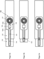
- FIGS 3a,b,c show an administration device according to the invention in various states of use.
- the administration device only the housing 102 as the first device part and the needle protection sleeve 103 as the second device part are shown in a simplified and exemplary manner.
- Other device parts, in particular as described above, are equally suitable for implementing the invention in a further developed form.
- Figure 3a shows an inventive administration device in a first state with an activatable identification means 100 comprising the carrier means 108, wherein the carrier means 108 mechanically accommodates the RFID circuit 106, the antenna 107, and the receiver 104, 105 and electrically connects them to the antenna connection 106b and the signal connection 106a.
- the carrier means 108 mechanically accommodates the RFID circuit 106, the antenna 107, and the receiver 104, 105 and electrically connects them to the antenna connection 106b and the signal connection 106a.
- one area or section 105 is operatively connected to the first device part 102
- another area or section 104 is operatively connected to the second device part 103.
- Figure 3b shows the administration device according to the invention in a second state, wherein the integrity of the receiver 104, 105 has been disturbed by the relative movement of the first device part 102 to the second device part 103 due to the said operative connection, in particular in a third state the conductor or conductor loop 104 shown, as in Figure 3c becomes visible, is permanently mechanically and electrically interrupted at a separation point 109.
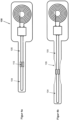
- Figures 4a and 4b show a modification of the sensor 104, 105 according to the invention in a first and second state, wherein here, due to the relative movement of the first device part 102 to the second device part 103, a reversible or irreversible deformation 109 of the carrier means and electrical elements 110 attached thereto occurs due to the aforementioned operative connection, whereby electrical parameters, in particular resistance or impedance values, are measurably changed.
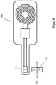
- Figure 5 shows a further modification of the activatable marking means 100 according to the invention, wherein here preferably a first sensor with a sensor 111 on the carrier means 108 and with a corresponding transmitter 112 on the second device part 103, for example a magnet or a ferromagnetic element, an electrical, inductive or electromagnetic source, a reflector, a damping element or a light guide or refractor.
- a first sensor with a sensor 111 on the carrier means 108 and with a corresponding transmitter 112 on the second device part 103
- a magnet or a ferromagnetic element for example a magnet or a ferromagnetic element, an electrical, inductive or electromagnetic source, a reflector, a damping element or a light guide or refractor.
- the corresponding field coupling or operative connection between the sensor 111 and the transmitter 112 is the relative movement of the first device part 102 to the second device part 103 is measurably changed.
- Figures 6a and 6b show a further modification of the activatable marking means according to the invention in a first and second state, wherein here preferably a galvanic connection by means of contacts 113 to corresponding counter-contacts, preferably to a conductor 114, is reversibly closed or opened as a function of the relative movement of a first device part 102 to the second device part 103.
- Figures 7a and 7b show a further modification of the activatable marking means according to the invention in a first and second state, wherein here preferably contacts 113 tap a conductor with a resistance coating, resulting in a variable resistance value which is a function of the relative position of the first device part 102 to the second device part 103.
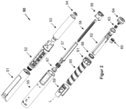
- Figure 2 Using a pen injector as an example, illustrates the device parts on which the invention can be implemented with an activatable marking means.
- the invention can be implemented on all device parts that, in particular, assume distinguishable positions and characterize significant states before, during, or after use of the pen injector or a comparable administration device.
- At least two of the individual parts of the auto-injector described below can preferably be used as the first and second device parts, provided they move relative to one another and thereby cause a change in the usage state:
- the mechanism moves in a first phase when preparing the auto-injector for use by opening the protective cover 51.
- a needle with a hollow cannula (not shown) can be placed on the distal end of the carpule holder 52.
- a dose to be administered can be dosed or corrected in a second phase by turning the dosing ring 61, whereby the drive sleeve 60 screws out of or into the housing 55 through the threaded insert 59.
- the freely rotatable knob 64 is not axially actuated during this second phase, and the coupling ring 66 therefore lies loosely between the drive sleeve 60 and the coupling sleeve 62, whereby the coupling sleeve 62 is not rotated.
- medication is dispensed by actuating the button 64 by applying an axial force in the distal direction, whereby the coupling ring 66 is pressed forcefully between the drive sleeve 60 and the coupling sleeve 62 on both sides, and the drive sleeve 60 screws itself back into the housing 55 through the threaded insert 59. Due to the force connection, the coupling sleeve 62 is rotated and simultaneously displaced distally along the axis L. The coupling sleeve 62, in turn, rotates the axially fixed output sleeve 57 by means of a sliding guide.
- the piston rod 58 is moved distally by a longitudinal guide engagement and a threaded engagement with the output sleeve 57 and the housing 55, whereby the flange 54 presses on the piston (not shown) of the carpule 53 and forces medicament through the hollow needle.
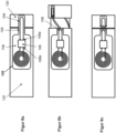
- Figure 8a shows an inventive administration device in a first state with an activatable identification means 100 comprising the carrier means 108, wherein the carrier means 108 mechanically accommodates the RFID circuit 106, the antenna 107, and the receiver 104, 105 and electrically connects them to the antenna connection 106b and the signal connection 106a.
- the carrier means 108 mechanically accommodates the RFID circuit 106, the antenna 107, and the receiver 104, 105 and electrically connects them to the antenna connection 106b and the signal connection 106a.
- one area or section or receiver part 105 is operatively connected to the first device part 120
- another area or section or receiver part 104 is operatively connected to the second device part 130.
- Figure 8b shows the administration device according to the invention in a second state, wherein the integrity of the carrier means or the receiver 104, 105 was disturbed by the relative movement of the first device part 120 to the second device part 130 due to the said operative connection, in particular in a third state the conductor or conductor loop 104 shown, as in Figure 8c becomes visible, is permanently mechanically and electrically interrupted at a separation point 109.
Landscapes
- Engineering & Computer Science (AREA)
- Health & Medical Sciences (AREA)
- Theoretical Computer Science (AREA)
- Physics & Mathematics (AREA)
- General Physics & Mathematics (AREA)
- Databases & Information Systems (AREA)
- General Health & Medical Sciences (AREA)
- Animal Behavior & Ethology (AREA)
- Hematology (AREA)
- Veterinary Medicine (AREA)
- Public Health (AREA)
- Life Sciences & Earth Sciences (AREA)
- Vascular Medicine (AREA)
- Anesthesiology (AREA)
- Biomedical Technology (AREA)
- Heart & Thoracic Surgery (AREA)
- Microelectronics & Electronic Packaging (AREA)
- Data Mining & Analysis (AREA)
- General Engineering & Computer Science (AREA)
- Computer Hardware Design (AREA)
- Toxicology (AREA)
- Computer Vision & Pattern Recognition (AREA)
- Electromagnetism (AREA)
- Artificial Intelligence (AREA)
- Computer Networks & Wireless Communication (AREA)
- Infusion, Injection, And Reservoir Apparatuses (AREA)
Claims (9)
- Dispositif d'administration pour l'administration parentérale d'un médicament présentant une première partie d'appareil (2, 55, 102, 120)au moins une deuxième partie d'appareil (3, 61, 103, 130), laquelle est mobile pendant ou après une administration par rapport à la première partie d'appareil à partir d'une première position dans au moins une deuxième position,ainsi qu'un moyen de marquage activable (100) présentantun moyen de support (108),un circuit RFID (106) avec une borne d'antenne (106b) et au moins une borne de signal (106a),au moins un capteur (104, 105) actif ou passif, lequel présente au moins deux parties de capteur (104, 105) reliées de manière opérationnelle dont au moins une partie de capteur (105) est reliée à la au moins une borne de signal (106a),ainsi qu'une antenne (107), laquelle est reliée à la borne d'antenne (106b), dans lequel le circuit RFID (106) est alimenté temporairement et au moyen de l'antenne (107) d'un dispositif de lecture, pour transmettre des informations sur une condition d' opération actuelle du dispositif d'administration au dispositif de lecture, dans lequel le circuit RFID fournit des codes différenciables, lesquels dépendent du signal, lequel s'applique sur la au moins une borne de signal, au dispositif de lecture,dans lequel le moyen de support (108) reçoit ou relie le circuit RFID (106), l'antenne (107) et la au moins une partie de capteur (105), dans lequel le moyen de support est réalisé de manière plate, peut porter des informations lisibles, et dans lequel le moyen de support est monté par coopération de formes ou à force avec au moins la première partie d'appareil et au moins en partie à l'intérieur du dispositif d'administration, en particulier dans une fente annulaire, laquelle est réalisée entre les parties d'appareil,dans lequel au moins une zone ou partie du moyen de support (108) présente la au moins une partie de capteur (105) et est reliée à au moins la première partie d'appareil (2, 55, 102, 120) et la deuxième partie de capteur (104) est reliée à la deuxième partie d'appareil (3, 61, 103, 130), dans lequel la au moins une zone du moyen de support (108) reçoit également la deuxième partie de capteur (104) et est reliée à la deuxième partie d'appareil (3, 61, 103, 130), de sorte que le mouvement relatif de la au moins deuxième partie d'appareil (3, 61, 103, 130) par rapport à la première partie d'appareil (2, 55, 102, 120) à partir de la première dans la au moins deuxième position déforme mécaniquement ou sépare la au moins une zone du moyen de support,dans lequel le mouvement relatif de la au moins deuxième partie d'appareil (3, 61, 103, 130) par rapport à la première partie d'appareil (2, 55, 102, 120) à partir de la première dans la au moins deuxième position provoque une modification de signal du capteur (104, 105)caractérisé en ce quele dispositif d'administration est un parmi un auto-injecteur (20), stylo injecteur (50), autopen, pompe à perfusion, pompe patch, inhalateur ou injecteur de bolus, et la première et la deuxième partie d'appareil comprend respectivement un parmi un boîtier (2, 55, 102, 120), un couvercle de protection (4, 51), des supports de mécanisme (5, 56), des porte-carpule ou seringue (1, 52), un capuchon (12), un manchon de protection d'aiguille (3, 103, 130), un extracteur (4), une carpule (53), un septum, une seringue, un piston, une bride (54), une tige de piston (7, 58), un manchon de dosage (60), une bague de dosage (61), un élément gradué (60), un mécanisme compteur (65), un élément de verrouillage (8, 15), un ressort d'entraînement (9, 10), un moteur d'entraînement, un cliquet (67), un élément à déclic (11, 12, 66, 67), un élément de blocage (67), un élément de déclenchement (6, 57), une gâchette (64), un accouplement (62), un filetage (58), une transmission (58, 65).
- Dispositif d'administration selon la revendication 1, caractérisé en ce que le dispositif d'administration est un auto-injecteur (20), et en ce que la première partie d'appareil (2, 102) ou la deuxième partie d'appareil (3, 103) est un parmi un manchon de protection d'aiguille (3, 103), un piston, une bride, une tige de piston (7, 58), un élément de verrouillage (8, 15), un ressort d'entraînement (9, 10), un moteur d'entraînement, un élément à déclic (11, 12), un élément de déclenchement (6).
- Dispositif d'administration selon la revendication 1 ou 2, caractérisé en ce que la déformation ou séparation (109) de la au moins une zone du moyen de support (108) influence la liaison opérationnelle des au moins deux parties de capteur (104, 105) et provoque une modification de signal du au moins un capteur (104, 105).
- Dispositif d'administration selon la revendication 3, caractérisé en ce que le au moins un capteur (104, 105) présente pour la modification de signal un conducteur (104) séparable ou une résistance (110) variable ou un convertisseur piézoélectrique (110).
- Dispositif d'administration selon la revendication 1 ou 2 ou 3, dans lequel la liaison opérationnelle entre la au moins une partie de capteur (105) [et] la deuxième partie de capteur (104) peut être établie de manière galvanique ou par l'intermédiaire d'un champ magnétique ou électrique ou électromagnétique, caractérisé en ce que le au moins un capteur (104, 105) présente respectivement des contacts (113) et contacts complémentaires (114, 115) correspondants ou respectivement des détecteurs (111) et transmetteurs (112) correspondants.
- Dispositif d'administration selon l'une quelconque des revendications précédentes, caractérisé en ce que le moyen de support est monté au moins en partie sur la surface extérieure ou visible de l'extérieur du dispositif d'administration.
- Dispositif d'administration selon l'une quelconque des revendications précédentes, caractérisé en ce que le circuit RFID (106) est compatible avec des appareils et systèmes, lesquels fonctionnent selon le protocole de transmission communication en champ proche NFC.
- Procédé mis en œuvre avec un dispositif d'administration selon l'une quelconque des revendications précédentes et au moins un dispositif de lecture, contenant au moins une des étapes suivantes :- la lecture d'un premier code provenant du circuit RFID, lorsque la deuxième partie d'appareil se trouve dans la première position- la lecture d'un deuxième code pouvant être différencié du premier provenant du circuit RFID, lorsque la deuxième partie d'appareil se trouve dans la deuxième position.
- Procédé selon la revendication 8 contenant en outre au moins une des étapes suivantes :- la délivrance de messages en fonction du code lu en particulier sous la forme de texte ou d'image sur un écran ou sous la forme d'un message vidéo ou audio ou d'une URL- la combinaison des codes ou messages avec une estampille temporelle- la mise en mémoire des codes ou messages dans le dispositif de lecture ou un emplacement réseau, une base de données ou un stockage en nuage- la comparaison des codes ou messages à des valeurs de consigne et la délivrance de confirmations ou d'avertissements correspondants- la transmission des codes ou messages à un système hôte ou un réseau ou une base de données ou un appareil de commande à distance ou un glucomètre ou un système de télémédecine- la consultation de bases de données et la délivrance de réponses correspondantes.
Applications Claiming Priority (2)
| Application Number | Priority Date | Filing Date | Title |
|---|---|---|---|
| CH01458/15A CH711618A2 (en) | 2015-10-07 | 2015-10-07 | Administration device with activatable identification means. |
| PCT/CH2016/000109 WO2017059553A1 (fr) | 2015-10-07 | 2016-08-18 | Injecteur à circuit électrique destructible après utilisation |
Publications (3)
| Publication Number | Publication Date |
|---|---|
| EP3359229A1 EP3359229A1 (fr) | 2018-08-15 |
| EP3359229B1 EP3359229B1 (fr) | 2022-05-18 |
| EP3359229B2 true EP3359229B2 (fr) | 2025-03-12 |
Family
ID=56842564
Family Applications (1)
| Application Number | Title | Priority Date | Filing Date |
|---|---|---|---|
| EP16757813.7A Active EP3359229B2 (fr) | 2015-10-07 | 2016-08-18 | Injecteur avec circuit electrique destructible par suite d'usage |
Country Status (6)
| Country | Link |
|---|---|
| US (1) | US10331996B2 (fr) |
| EP (1) | EP3359229B2 (fr) |
| CH (1) | CH711618A2 (fr) |
| DK (1) | DK3359229T4 (fr) |
| TW (1) | TWI656894B (fr) |
| WO (1) | WO2017059553A1 (fr) |
Families Citing this family (15)
| Publication number | Priority date | Publication date | Assignee | Title |
|---|---|---|---|---|
| CA2952167C (fr) | 2014-06-13 | 2023-06-13 | Aterica Inc. | Systeme et dispositif de gestion de dispositifs d'administration de medicaments |
| EP3519021B1 (fr) * | 2016-10-03 | 2025-08-13 | Ypsomed AG | Module électronique de surveillance de dispositifs d'injection |
| CH713114A2 (de) | 2016-11-09 | 2018-05-15 | Tecpharma Licensing Ag | Elektronisches Zusatzmodul für Injektionsgeräte. |
| LT3589340T (lt) | 2017-02-28 | 2026-01-12 | Eli Lilly And Company | Vaistų leidimo įrenginio dozės aptikimas ir vaistų identifikavimas |
| CN107243108B (zh) * | 2017-07-03 | 2024-02-06 | 玉环天来科技有限公司 | 上自毁护套机构 |
| DK3727521T3 (da) * | 2017-12-21 | 2024-09-23 | Sanofi Sa | Bestemmelse af en status af en injektion |
| DK3755403T3 (da) | 2018-02-22 | 2024-09-23 | Lilly Co Eli | Medikamenttilførselsanordning med et registreret element |
| EP4681751A3 (fr) * | 2019-07-01 | 2026-03-25 | Becton Dickinson France | Capuchon de pointe pour dispositif d'injection médical |
| TWI777138B (zh) * | 2020-03-02 | 2022-09-11 | 廣達電腦股份有限公司 | 胰島素劑量偵測裝置 |
| EP3878491A1 (fr) | 2020-03-10 | 2021-09-15 | Ypsomed AG | Emballage de dispositif médical comportant un support d'appariement nfc |
| AU2021266748A1 (en) * | 2020-05-07 | 2022-12-08 | Becton, Dickinson And Company | Device, system, and method for detection of medical device components and/or mating thereof |
| TWI776461B (zh) * | 2021-04-12 | 2022-09-01 | 國立陽明交通大學 | 吸入器輔助裝置 |
| EP4079352A1 (fr) * | 2021-04-21 | 2022-10-26 | Becton Dickinson France | Couvre-aiguille pour un dispositif d'injection médical |
| US12124905B1 (en) * | 2021-12-17 | 2024-10-22 | Wells Fargo Bank, N.A. | Transaction instrument with features for destruction and disposal |
| US20250367382A1 (en) * | 2024-05-14 | 2025-12-04 | Gilead Sciences, Inc. | Medical injections and related devices and methods |
Family Cites Families (16)
| Publication number | Priority date | Publication date | Assignee | Title |
|---|---|---|---|---|
| US3126004A (en) * | 1964-03-24 | Cartridge with antipilfering pistojf | ||
| TW445158B (en) * | 1999-10-27 | 2001-07-11 | Lin Bi Sheng | Semi-disposable injector |
| US20060152364A1 (en) | 2004-12-30 | 2006-07-13 | Walton Charles A | RFID with field changeable identification |
| US8361026B2 (en) | 2005-02-01 | 2013-01-29 | Intelliject, Inc. | Apparatus and methods for self-administration of vaccines and other medicaments |
| GB2451769B (en) * | 2005-02-01 | 2009-12-09 | Intelliject Llc | Devices, systems, and methods for medicament delivery |
| US20060214789A1 (en) | 2005-03-24 | 2006-09-28 | Joshua Posamentier | Tamper detection with RFID tag |
| TWI267390B (en) * | 2005-06-06 | 2006-12-01 | Chan-Yun Yang | Safe apparatus for processing used syringe |
| TWI271204B (en) * | 2005-08-31 | 2007-01-21 | Chung-Yu Yang | Safety syringe |
| US20070095160A1 (en) * | 2005-11-03 | 2007-05-03 | The Boeing Company | Structural assessment and monitoring system and associated method |
| WO2009024562A1 (fr) | 2007-08-17 | 2009-02-26 | Novo Nordisk A/S | Dispositif médical avec capteur de valeur |
| WO2009140782A1 (fr) | 2008-05-23 | 2009-11-26 | Tecpharma Licensing Ag | Surveillance de la pression dans un appareil d'administration modulaire |
| KR101113554B1 (ko) * | 2010-07-29 | 2012-02-24 | 삼성에스디아이 주식회사 | 이차 전지 |
| EP2656865A1 (fr) | 2012-04-24 | 2013-10-30 | Sanofi-Aventis Deutschland GmbH | Porte-seringue avec gaine de protection d'aiguille et mémoire de données pour auto-injecteur médical |
| DE102012112297A1 (de) * | 2012-12-14 | 2014-06-18 | Schreiner Group Gmbh & Co. Kg | Verschlusselement für ein Gefäß |
| EP3327632B1 (fr) * | 2013-05-15 | 2021-01-20 | Berlinger & Co. AG | Emballage pour produit pharmaceutique comprenant une étiquette électronique miniaturisée permettant de surveiller l'intégrité du produit |
| US10226577B2 (en) | 2013-11-13 | 2019-03-12 | Novo Nordisk A/S | Drug delivery device with time indicator feature |
-
2015
- 2015-10-07 CH CH01458/15A patent/CH711618A2/en not_active Application Discontinuation
-
2016
- 2016-08-18 WO PCT/CH2016/000109 patent/WO2017059553A1/fr not_active Ceased
- 2016-08-18 DK DK16757813.7T patent/DK3359229T4/da active
- 2016-08-18 EP EP16757813.7A patent/EP3359229B2/fr active Active
- 2016-09-21 TW TW105130476A patent/TWI656894B/zh active
-
2018
- 2018-04-03 US US15/944,646 patent/US10331996B2/en active Active
Also Published As
| Publication number | Publication date |
|---|---|
| TWI656894B (zh) | 2019-04-21 |
| CH711618A2 (en) | 2017-04-13 |
| US20180225560A1 (en) | 2018-08-09 |
| TW201726187A (zh) | 2017-08-01 |
| DK3359229T4 (da) | 2025-06-10 |
| EP3359229B1 (fr) | 2022-05-18 |
| DK3359229T3 (da) | 2022-08-08 |
| EP3359229A1 (fr) | 2018-08-15 |
| WO2017059553A1 (fr) | 2017-04-13 |
| US10331996B2 (en) | 2019-06-25 |
Similar Documents
| Publication | Publication Date | Title |
|---|---|---|
| EP3359229B2 (fr) | Injecteur avec circuit electrique destructible par suite d'usage | |
| EP3930793B1 (fr) | Auto-injecteur à détection de distribution | |
| EP3294373B1 (fr) | Dispositif d'injection adaptable | |
| EP3538183B1 (fr) | Module électronique complémentaire pour appareils d'injection | |
| EP2414009B1 (fr) | Dispositif destiné à l'administration d'insuline hors d'une cartouche | |
| EP1043037B1 (fr) | Injecteur de medicament du type stylo | |
| DE69836026T2 (de) | Injektionsvorrichtung | |
| US10603442B2 (en) | Accessory device with snap feature | |
| DE202016009234U1 (de) | Überwachungseinheit | |
| EP2203110A1 (fr) | Système médical à système de surveillance consommable | |
| CH717022A2 (de) | Verabreichungsvorrichtung mit auslesbarem Code. | |
| WO2021254840A1 (fr) | Détermination de l'état d'utilisation d'un dispositif pour l'administration unique d'un médicament | |
| EP3386564B1 (fr) | Dispositif d'injection permettant d'injecter des quantités dosées d'un fluide thérapeutique | |
| WO2017011926A1 (fr) | Dispositif d'injection comprenant des éléments d'accouplement | |
| EP4691521A1 (fr) | Ensemble de commande amélioré pour seringue | |
| EP4623961A1 (fr) | Dispositif d'injection avec lecteur de communication en champ proche | |
| DE102024116579A1 (de) | Ermittlung des Benutzungsstatus einer Vorrichtung zur einmaligen Verabreichung von Arzneistoff | |
| DE102016120926A1 (de) | Injektionsvorrichtung zur Injektion dosierter Mengen eines flüssigen Therapeutikums | |
| DE102016104101A1 (de) | Injektionsvorrichtung zur Injektion dosierter Mengen eines flüssigen Therapeutikums | |
| EP4094789A1 (fr) | Appoint comprenant un actionneur pour dispositif d'administration de médicaments |
Legal Events
| Date | Code | Title | Description |
|---|---|---|---|
| STAA | Information on the status of an ep patent application or granted ep patent |
Free format text: STATUS: UNKNOWN |
|
| STAA | Information on the status of an ep patent application or granted ep patent |
Free format text: STATUS: THE INTERNATIONAL PUBLICATION HAS BEEN MADE |
|
| PUAI | Public reference made under article 153(3) epc to a published international application that has entered the european phase |
Free format text: ORIGINAL CODE: 0009012 |
|
| STAA | Information on the status of an ep patent application or granted ep patent |
Free format text: STATUS: REQUEST FOR EXAMINATION WAS MADE |
|
| 17P | Request for examination filed |
Effective date: 20180507 |
|
| AK | Designated contracting states |
Kind code of ref document: A1 Designated state(s): AL AT BE BG CH CY CZ DE DK EE ES FI FR GB GR HR HU IE IS IT LI LT LU LV MC MK MT NL NO PL PT RO RS SE SI SK SM TR |
|
| AX | Request for extension of the european patent |
Extension state: BA ME |
|
| DAV | Request for validation of the european patent (deleted) | ||
| DAX | Request for extension of the european patent (deleted) | ||
| STAA | Information on the status of an ep patent application or granted ep patent |
Free format text: STATUS: EXAMINATION IS IN PROGRESS |
|
| 17Q | First examination report despatched |
Effective date: 20190319 |
|
| RAP1 | Party data changed (applicant data changed or rights of an application transferred) |
Owner name: YPSOMED AG |
|
| GRAP | Despatch of communication of intention to grant a patent |
Free format text: ORIGINAL CODE: EPIDOSNIGR1 |
|
| STAA | Information on the status of an ep patent application or granted ep patent |
Free format text: STATUS: GRANT OF PATENT IS INTENDED |
|
| INTG | Intention to grant announced |
Effective date: 20211210 |
|
| GRAS | Grant fee paid |
Free format text: ORIGINAL CODE: EPIDOSNIGR3 |
|
| GRAA | (expected) grant |
Free format text: ORIGINAL CODE: 0009210 |
|
| STAA | Information on the status of an ep patent application or granted ep patent |
Free format text: STATUS: THE PATENT HAS BEEN GRANTED |
|
| AK | Designated contracting states |
Kind code of ref document: B1 Designated state(s): AL AT BE BG CH CY CZ DE DK EE ES FI FR GB GR HR HU IE IS IT LI LT LU LV MC MK MT NL NO PL PT RO RS SE SI SK SM TR |
|
| REG | Reference to a national code |
Ref country code: GB Ref legal event code: FG4D Free format text: NOT ENGLISH |
|
| REG | Reference to a national code |
Ref country code: CH Ref legal event code: EP |
|
| REG | Reference to a national code |
Ref country code: IE Ref legal event code: FG4D Free format text: LANGUAGE OF EP DOCUMENT: GERMAN |
|
| REG | Reference to a national code |
Ref country code: DE Ref legal event code: R096 Ref document number: 502016014908 Country of ref document: DE |
|
| REG | Reference to a national code |
Ref country code: AT Ref legal event code: REF Ref document number: 1492797 Country of ref document: AT Kind code of ref document: T Effective date: 20220615 |
|
| REG | Reference to a national code |
Ref country code: DK Ref legal event code: T3 Effective date: 20220805 |
|
| REG | Reference to a national code |
Ref country code: LT Ref legal event code: MG9D |
|
| REG | Reference to a national code |
Ref country code: NL Ref legal event code: MP Effective date: 20220518 |
|
| PG25 | Lapsed in a contracting state [announced via postgrant information from national office to epo] |
Ref country code: SE Free format text: LAPSE BECAUSE OF FAILURE TO SUBMIT A TRANSLATION OF THE DESCRIPTION OR TO PAY THE FEE WITHIN THE PRESCRIBED TIME-LIMIT Effective date: 20220518 Ref country code: PT Free format text: LAPSE BECAUSE OF FAILURE TO SUBMIT A TRANSLATION OF THE DESCRIPTION OR TO PAY THE FEE WITHIN THE PRESCRIBED TIME-LIMIT Effective date: 20220919 Ref country code: NO Free format text: LAPSE BECAUSE OF FAILURE TO SUBMIT A TRANSLATION OF THE DESCRIPTION OR TO PAY THE FEE WITHIN THE PRESCRIBED TIME-LIMIT Effective date: 20220818 Ref country code: NL Free format text: LAPSE BECAUSE OF FAILURE TO SUBMIT A TRANSLATION OF THE DESCRIPTION OR TO PAY THE FEE WITHIN THE PRESCRIBED TIME-LIMIT Effective date: 20220518 Ref country code: LT Free format text: LAPSE BECAUSE OF FAILURE TO SUBMIT A TRANSLATION OF THE DESCRIPTION OR TO PAY THE FEE WITHIN THE PRESCRIBED TIME-LIMIT Effective date: 20220518 Ref country code: HR Free format text: LAPSE BECAUSE OF FAILURE TO SUBMIT A TRANSLATION OF THE DESCRIPTION OR TO PAY THE FEE WITHIN THE PRESCRIBED TIME-LIMIT Effective date: 20220518 Ref country code: GR Free format text: LAPSE BECAUSE OF FAILURE TO SUBMIT A TRANSLATION OF THE DESCRIPTION OR TO PAY THE FEE WITHIN THE PRESCRIBED TIME-LIMIT Effective date: 20220819 Ref country code: FI Free format text: LAPSE BECAUSE OF FAILURE TO SUBMIT A TRANSLATION OF THE DESCRIPTION OR TO PAY THE FEE WITHIN THE PRESCRIBED TIME-LIMIT Effective date: 20220518 Ref country code: ES Free format text: LAPSE BECAUSE OF FAILURE TO SUBMIT A TRANSLATION OF THE DESCRIPTION OR TO PAY THE FEE WITHIN THE PRESCRIBED TIME-LIMIT Effective date: 20220518 Ref country code: BG Free format text: LAPSE BECAUSE OF FAILURE TO SUBMIT A TRANSLATION OF THE DESCRIPTION OR TO PAY THE FEE WITHIN THE PRESCRIBED TIME-LIMIT Effective date: 20220818 |
|
| PG25 | Lapsed in a contracting state [announced via postgrant information from national office to epo] |
Ref country code: RS Free format text: LAPSE BECAUSE OF FAILURE TO SUBMIT A TRANSLATION OF THE DESCRIPTION OR TO PAY THE FEE WITHIN THE PRESCRIBED TIME-LIMIT Effective date: 20220518 Ref country code: PL Free format text: LAPSE BECAUSE OF FAILURE TO SUBMIT A TRANSLATION OF THE DESCRIPTION OR TO PAY THE FEE WITHIN THE PRESCRIBED TIME-LIMIT Effective date: 20220518 Ref country code: LV Free format text: LAPSE BECAUSE OF FAILURE TO SUBMIT A TRANSLATION OF THE DESCRIPTION OR TO PAY THE FEE WITHIN THE PRESCRIBED TIME-LIMIT Effective date: 20220518 Ref country code: IS Free format text: LAPSE BECAUSE OF FAILURE TO SUBMIT A TRANSLATION OF THE DESCRIPTION OR TO PAY THE FEE WITHIN THE PRESCRIBED TIME-LIMIT Effective date: 20220918 |
|
| PG25 | Lapsed in a contracting state [announced via postgrant information from national office to epo] |
Ref country code: SM Free format text: LAPSE BECAUSE OF FAILURE TO SUBMIT A TRANSLATION OF THE DESCRIPTION OR TO PAY THE FEE WITHIN THE PRESCRIBED TIME-LIMIT Effective date: 20220518 Ref country code: SK Free format text: LAPSE BECAUSE OF FAILURE TO SUBMIT A TRANSLATION OF THE DESCRIPTION OR TO PAY THE FEE WITHIN THE PRESCRIBED TIME-LIMIT Effective date: 20220518 Ref country code: RO Free format text: LAPSE BECAUSE OF FAILURE TO SUBMIT A TRANSLATION OF THE DESCRIPTION OR TO PAY THE FEE WITHIN THE PRESCRIBED TIME-LIMIT Effective date: 20220518 Ref country code: EE Free format text: LAPSE BECAUSE OF FAILURE TO SUBMIT A TRANSLATION OF THE DESCRIPTION OR TO PAY THE FEE WITHIN THE PRESCRIBED TIME-LIMIT Effective date: 20220518 Ref country code: CZ Free format text: LAPSE BECAUSE OF FAILURE TO SUBMIT A TRANSLATION OF THE DESCRIPTION OR TO PAY THE FEE WITHIN THE PRESCRIBED TIME-LIMIT Effective date: 20220518 |
|
| REG | Reference to a national code |
Ref country code: DE Ref legal event code: R026 Ref document number: 502016014908 Country of ref document: DE |
|
| PLBI | Opposition filed |
Free format text: ORIGINAL CODE: 0009260 |
|
| PLAX | Notice of opposition and request to file observation + time limit sent |
Free format text: ORIGINAL CODE: EPIDOSNOBS2 |
|
| 26 | Opposition filed |
Opponent name: SANOFI-AVENTIS DEUTSCHLAND GMBH Effective date: 20230216 |
|
| PG25 | Lapsed in a contracting state [announced via postgrant information from national office to epo] |
Ref country code: MC Free format text: LAPSE BECAUSE OF FAILURE TO SUBMIT A TRANSLATION OF THE DESCRIPTION OR TO PAY THE FEE WITHIN THE PRESCRIBED TIME-LIMIT Effective date: 20220518 Ref country code: AL Free format text: LAPSE BECAUSE OF FAILURE TO SUBMIT A TRANSLATION OF THE DESCRIPTION OR TO PAY THE FEE WITHIN THE PRESCRIBED TIME-LIMIT Effective date: 20220518 |
|
| PG25 | Lapsed in a contracting state [announced via postgrant information from national office to epo] |
Ref country code: LU Free format text: LAPSE BECAUSE OF NON-PAYMENT OF DUE FEES Effective date: 20220818 |
|
| REG | Reference to a national code |
Ref country code: BE Ref legal event code: MM Effective date: 20220831 |
|
| PG25 | Lapsed in a contracting state [announced via postgrant information from national office to epo] |
Ref country code: SI Free format text: LAPSE BECAUSE OF FAILURE TO SUBMIT A TRANSLATION OF THE DESCRIPTION OR TO PAY THE FEE WITHIN THE PRESCRIBED TIME-LIMIT Effective date: 20220518 |
|
| P01 | Opt-out of the competence of the unified patent court (upc) registered |
Effective date: 20230524 |
|
| PLBB | Reply of patent proprietor to notice(s) of opposition received |
Free format text: ORIGINAL CODE: EPIDOSNOBS3 |
|
| PG25 | Lapsed in a contracting state [announced via postgrant information from national office to epo] |
Ref country code: IE Free format text: LAPSE BECAUSE OF NON-PAYMENT OF DUE FEES Effective date: 20220818 |
|
| PG25 | Lapsed in a contracting state [announced via postgrant information from national office to epo] |
Ref country code: BE Free format text: LAPSE BECAUSE OF NON-PAYMENT OF DUE FEES Effective date: 20220831 |
|
| REG | Reference to a national code |
Ref country code: AT Ref legal event code: MM01 Ref document number: 1492797 Country of ref document: AT Kind code of ref document: T Effective date: 20220818 |
|
| PG25 | Lapsed in a contracting state [announced via postgrant information from national office to epo] |
Ref country code: AT Free format text: LAPSE BECAUSE OF NON-PAYMENT OF DUE FEES Effective date: 20220818 |
|
| PG25 | Lapsed in a contracting state [announced via postgrant information from national office to epo] |
Ref country code: IT Free format text: LAPSE BECAUSE OF FAILURE TO SUBMIT A TRANSLATION OF THE DESCRIPTION OR TO PAY THE FEE WITHIN THE PRESCRIBED TIME-LIMIT Effective date: 20220518 |
|
| PLAY | Examination report in opposition despatched + time limit |
Free format text: ORIGINAL CODE: EPIDOSNORE2 |
|
| PG25 | Lapsed in a contracting state [announced via postgrant information from national office to epo] |
Ref country code: HU Free format text: LAPSE BECAUSE OF FAILURE TO SUBMIT A TRANSLATION OF THE DESCRIPTION OR TO PAY THE FEE WITHIN THE PRESCRIBED TIME-LIMIT; INVALID AB INITIO Effective date: 20160818 |
|
| PG25 | Lapsed in a contracting state [announced via postgrant information from national office to epo] |
Ref country code: CY Free format text: LAPSE BECAUSE OF FAILURE TO SUBMIT A TRANSLATION OF THE DESCRIPTION OR TO PAY THE FEE WITHIN THE PRESCRIBED TIME-LIMIT Effective date: 20220511 |
|
| PLBC | Reply to examination report in opposition received |
Free format text: ORIGINAL CODE: EPIDOSNORE3 |
|
| PG25 | Lapsed in a contracting state [announced via postgrant information from national office to epo] |
Ref country code: MK Free format text: LAPSE BECAUSE OF FAILURE TO SUBMIT A TRANSLATION OF THE DESCRIPTION OR TO PAY THE FEE WITHIN THE PRESCRIBED TIME-LIMIT Effective date: 20220511 |
|
| PG25 | Lapsed in a contracting state [announced via postgrant information from national office to epo] |
Ref country code: MT Free format text: LAPSE BECAUSE OF FAILURE TO SUBMIT A TRANSLATION OF THE DESCRIPTION OR TO PAY THE FEE WITHIN THE PRESCRIBED TIME-LIMIT Effective date: 20220511 |
|
| PG25 | Lapsed in a contracting state [announced via postgrant information from national office to epo] |
Ref country code: BG Free format text: LAPSE BECAUSE OF FAILURE TO SUBMIT A TRANSLATION OF THE DESCRIPTION OR TO PAY THE FEE WITHIN THE PRESCRIBED TIME-LIMIT Effective date: 20220518 |
|
| PG25 | Lapsed in a contracting state [announced via postgrant information from national office to epo] |
Ref country code: BG Free format text: LAPSE BECAUSE OF FAILURE TO SUBMIT A TRANSLATION OF THE DESCRIPTION OR TO PAY THE FEE WITHIN THE PRESCRIBED TIME-LIMIT Effective date: 20220518 |
|
| PUAH | Patent maintained in amended form |
Free format text: ORIGINAL CODE: 0009272 |
|
| STAA | Information on the status of an ep patent application or granted ep patent |
Free format text: STATUS: PATENT MAINTAINED AS AMENDED |
|
| 27A | Patent maintained in amended form |
Effective date: 20250312 |
|
| AK | Designated contracting states |
Kind code of ref document: B2 Designated state(s): AL AT BE BG CH CY CZ DE DK EE ES FI FR GB GR HR HU IE IS IT LI LT LU LV MC MK MT NL NO PL PT RO RS SE SI SK SM TR |
|
| REG | Reference to a national code |
Ref country code: DE Ref legal event code: R102 Ref document number: 502016014908 Country of ref document: DE |
|
| REG | Reference to a national code |
Ref country code: DK Ref legal event code: T4 Effective date: 20250606 |
|
| PGFP | Annual fee paid to national office [announced via postgrant information from national office to epo] |
Ref country code: DE Payment date: 20250819 Year of fee payment: 10 Ref country code: DK Payment date: 20250821 Year of fee payment: 10 |
|
| PGFP | Annual fee paid to national office [announced via postgrant information from national office to epo] |
Ref country code: GB Payment date: 20250822 Year of fee payment: 10 |
|
| PGFP | Annual fee paid to national office [announced via postgrant information from national office to epo] |
Ref country code: FR Payment date: 20250821 Year of fee payment: 10 |
|
| PGFP | Annual fee paid to national office [announced via postgrant information from national office to epo] |
Ref country code: CH Payment date: 20250901 Year of fee payment: 10 |
|
| PG25 | Lapsed in a contracting state [announced via postgrant information from national office to epo] |
Ref country code: TR Free format text: LAPSE BECAUSE OF FAILURE TO SUBMIT A TRANSLATION OF THE DESCRIPTION OR TO PAY THE FEE WITHIN THE PRESCRIBED TIME-LIMIT Effective date: 20220518 |