EP3359239B1 - Appareil de dérivation d'occlusion muni d'une aiguille de ré-entrée et d'un ballonnet de stabilisation distal - Google Patents
Appareil de dérivation d'occlusion muni d'une aiguille de ré-entrée et d'un ballonnet de stabilisation distal Download PDFInfo
- Publication number
- EP3359239B1 EP3359239B1 EP16781978.8A EP16781978A EP3359239B1 EP 3359239 B1 EP3359239 B1 EP 3359239B1 EP 16781978 A EP16781978 A EP 16781978A EP 3359239 B1 EP3359239 B1 EP 3359239B1
- Authority
- EP
- European Patent Office
- Prior art keywords
- outer shaft
- needle
- component
- shaft component
- distal
- Prior art date
- Legal status (The legal status is an assumption and is not a legal conclusion. Google has not performed a legal analysis and makes no representation as to the accuracy of the status listed.)
- Active
Links
Images










Classifications
-
- A—HUMAN NECESSITIES
- A61—MEDICAL OR VETERINARY SCIENCE; HYGIENE
- A61B—DIAGNOSIS; SURGERY; IDENTIFICATION
- A61B17/00—Surgical instruments, devices or methods
- A61B17/22—Implements for squeezing-off ulcers or the like on inner organs of the body; Implements for scraping-out cavities of body organs, e.g. bones; for invasive removal or destruction of calculus using mechanical vibrations; for removing obstructions in blood vessels, not otherwise provided for
-
- A—HUMAN NECESSITIES
- A61—MEDICAL OR VETERINARY SCIENCE; HYGIENE
- A61B—DIAGNOSIS; SURGERY; IDENTIFICATION
- A61B17/00—Surgical instruments, devices or methods
- A61B17/34—Trocars; Puncturing needles
- A61B17/3478—Endoscopic needles, e.g. for infusion
-
- A—HUMAN NECESSITIES
- A61—MEDICAL OR VETERINARY SCIENCE; HYGIENE
- A61M—DEVICES FOR INTRODUCING MEDIA INTO, OR ONTO, THE BODY; DEVICES FOR TRANSDUCING BODY MEDIA OR FOR TAKING MEDIA FROM THE BODY; DEVICES FOR PRODUCING OR ENDING SLEEP OR STUPOR
- A61M25/00—Catheters; Hollow probes
- A61M25/01—Introducing, guiding, advancing, emplacing or holding catheters
- A61M25/0194—Tunnelling catheters
-
- A—HUMAN NECESSITIES
- A61—MEDICAL OR VETERINARY SCIENCE; HYGIENE
- A61B—DIAGNOSIS; SURGERY; IDENTIFICATION
- A61B17/00—Surgical instruments, devices or methods
- A61B17/00234—Surgical instruments, devices or methods for minimally invasive surgery
- A61B2017/00292—Surgical instruments, devices or methods for minimally invasive surgery mounted on or guided by flexible, e.g. catheter-like, means
- A61B2017/003—Steerable
- A61B2017/00318—Steering mechanisms
- A61B2017/00331—Steering mechanisms with preformed bends
-
- A—HUMAN NECESSITIES
- A61—MEDICAL OR VETERINARY SCIENCE; HYGIENE
- A61B—DIAGNOSIS; SURGERY; IDENTIFICATION
- A61B17/00—Surgical instruments, devices or methods
- A61B17/22—Implements for squeezing-off ulcers or the like on inner organs of the body; Implements for scraping-out cavities of body organs, e.g. bones; for invasive removal or destruction of calculus using mechanical vibrations; for removing obstructions in blood vessels, not otherwise provided for
- A61B2017/22001—Angioplasty, e.g. PCTA
-
- A—HUMAN NECESSITIES
- A61—MEDICAL OR VETERINARY SCIENCE; HYGIENE
- A61B—DIAGNOSIS; SURGERY; IDENTIFICATION
- A61B17/00—Surgical instruments, devices or methods
- A61B17/22—Implements for squeezing-off ulcers or the like on inner organs of the body; Implements for scraping-out cavities of body organs, e.g. bones; for invasive removal or destruction of calculus using mechanical vibrations; for removing obstructions in blood vessels, not otherwise provided for
- A61B2017/22051—Implements for squeezing-off ulcers or the like on inner organs of the body; Implements for scraping-out cavities of body organs, e.g. bones; for invasive removal or destruction of calculus using mechanical vibrations; for removing obstructions in blood vessels, not otherwise provided for with an inflatable part, e.g. balloon, for positioning, blocking, or immobilisation
- A61B2017/22065—Functions of balloons
- A61B2017/22069—Immobilising; Stabilising
-
- A—HUMAN NECESSITIES
- A61—MEDICAL OR VETERINARY SCIENCE; HYGIENE
- A61B—DIAGNOSIS; SURGERY; IDENTIFICATION
- A61B17/00—Surgical instruments, devices or methods
- A61B17/22—Implements for squeezing-off ulcers or the like on inner organs of the body; Implements for scraping-out cavities of body organs, e.g. bones; for invasive removal or destruction of calculus using mechanical vibrations; for removing obstructions in blood vessels, not otherwise provided for
- A61B2017/22094—Implements for squeezing-off ulcers or the like on inner organs of the body; Implements for scraping-out cavities of body organs, e.g. bones; for invasive removal or destruction of calculus using mechanical vibrations; for removing obstructions in blood vessels, not otherwise provided for for crossing total occlusions, i.e. piercing
- A61B2017/22095—Implements for squeezing-off ulcers or the like on inner organs of the body; Implements for scraping-out cavities of body organs, e.g. bones; for invasive removal or destruction of calculus using mechanical vibrations; for removing obstructions in blood vessels, not otherwise provided for for crossing total occlusions, i.e. piercing accessing a blood vessel true lumen from the sub-intimal space
-
- A—HUMAN NECESSITIES
- A61—MEDICAL OR VETERINARY SCIENCE; HYGIENE
- A61M—DEVICES FOR INTRODUCING MEDIA INTO, OR ONTO, THE BODY; DEVICES FOR TRANSDUCING BODY MEDIA OR FOR TAKING MEDIA FROM THE BODY; DEVICES FOR PRODUCING OR ENDING SLEEP OR STUPOR
- A61M25/00—Catheters; Hollow probes
- A61M25/0067—Catheters; Hollow probes characterised by the distal end, e.g. tips
- A61M25/0082—Catheter tip comprising a tool
- A61M25/0084—Catheter tip comprising a tool being one or more injection needles
- A61M2025/0092—Single injection needle protruding laterally from the distal tip
-
- A—HUMAN NECESSITIES
- A61—MEDICAL OR VETERINARY SCIENCE; HYGIENE
- A61M—DEVICES FOR INTRODUCING MEDIA INTO, OR ONTO, THE BODY; DEVICES FOR TRANSDUCING BODY MEDIA OR FOR TAKING MEDIA FROM THE BODY; DEVICES FOR PRODUCING OR ENDING SLEEP OR STUPOR
- A61M25/00—Catheters; Hollow probes
- A61M25/01—Introducing, guiding, advancing, emplacing or holding catheters
- A61M25/0194—Tunnelling catheters
- A61M2025/0197—Tunnelling catheters for creating an artificial passage within the body, e.g. in order to go around occlusions
-
- A—HUMAN NECESSITIES
- A61—MEDICAL OR VETERINARY SCIENCE; HYGIENE
- A61M—DEVICES FOR INTRODUCING MEDIA INTO, OR ONTO, THE BODY; DEVICES FOR TRANSDUCING BODY MEDIA OR FOR TAKING MEDIA FROM THE BODY; DEVICES FOR PRODUCING OR ENDING SLEEP OR STUPOR
- A61M25/00—Catheters; Hollow probes
- A61M25/01—Introducing, guiding, advancing, emplacing or holding catheters
- A61M25/02—Holding devices, e.g. on the body
- A61M2025/0293—Catheter, guide wire or the like with means for holding, centering, anchoring or frictionally engaging the device within an artificial lumen, e.g. tube
-
- A—HUMAN NECESSITIES
- A61—MEDICAL OR VETERINARY SCIENCE; HYGIENE
- A61M—DEVICES FOR INTRODUCING MEDIA INTO, OR ONTO, THE BODY; DEVICES FOR TRANSDUCING BODY MEDIA OR FOR TAKING MEDIA FROM THE BODY; DEVICES FOR PRODUCING OR ENDING SLEEP OR STUPOR
- A61M25/00—Catheters; Hollow probes
- A61M25/10—Balloon catheters
- A61M2025/1043—Balloon catheters with special features or adapted for special applications
- A61M2025/1072—Balloon catheters with special features or adapted for special applications having balloons with two or more compartments
-
- A—HUMAN NECESSITIES
- A61—MEDICAL OR VETERINARY SCIENCE; HYGIENE
- A61M—DEVICES FOR INTRODUCING MEDIA INTO, OR ONTO, THE BODY; DEVICES FOR TRANSDUCING BODY MEDIA OR FOR TAKING MEDIA FROM THE BODY; DEVICES FOR PRODUCING OR ENDING SLEEP OR STUPOR
- A61M25/00—Catheters; Hollow probes
- A61M25/0067—Catheters; Hollow probes characterised by the distal end, e.g. tips
- A61M25/0082—Catheter tip comprising a tool
- A61M25/0084—Catheter tip comprising a tool being one or more injection needles
-
- A—HUMAN NECESSITIES
- A61—MEDICAL OR VETERINARY SCIENCE; HYGIENE
- A61M—DEVICES FOR INTRODUCING MEDIA INTO, OR ONTO, THE BODY; DEVICES FOR TRANSDUCING BODY MEDIA OR FOR TAKING MEDIA FROM THE BODY; DEVICES FOR PRODUCING OR ENDING SLEEP OR STUPOR
- A61M25/00—Catheters; Hollow probes
- A61M25/10—Balloon catheters
- A61M25/1002—Balloon catheters characterised by balloon shape
Definitions
- the invention relates generally to an occlusion bypassing apparatus for subintimally bypassing a blockage in a blood vessel such as a chronic total occlusion and reentering the true lumen of the blood vessel beyond the blockage.
- Cardiovascular disease including atherosclerosis, is a serious ailment for many people that may in some cases lead to death.
- One method for treating atherosclerosis and other forms of arterial lumen narrowing is percutaneous transluminal angioplasty, commonly referred to as “angioplasty” or “PTA,” or “PTCA” when performed in the coronary arteries.
- angioplasty percutaneous transluminal angioplasty
- PTA percutaneous transluminal angioplasty
- PTCA percutaneous transluminal angioplasty
- the objective in angioplasty is to restore adequate blood flow through the affected artery, which may be accomplished by inflating a balloon of a balloon catheter within the narrowed lumen of the artery to dilate the vessel.
- the anatomy of arteries varies widely from patient to patient. Often a patient's arteries are irregularly shaped, highly tortuous and very narrow. The tortuous configuration of the arteries may present difficulties to a clinician in advancement of the balloon catheter to a treatment site. In addition, in some instances, the extent to which the lumen is narrowed at the treatment site is so severe that the lumen is completely or nearly completely obstructed, which may be described as a total occlusion. Total or near-total occlusions in arteries can prevent all or nearly all of the blood flow through the affected arteries. If the occlusion has been established for a long period of time, the lesion may be referred to as a chronic total occlusion or CTO.
- CTO chronic total occlusion
- Chronic total occlusions can occur in coronary as well as peripheral arteries. Chronic total occlusions are often characterized by extensive plaque formation and typically include a fibrous cap surrounding softer plaque material. This fibrous cap may present a surface that is difficult to penetrate with a conventional medical guidewire.
- a number of devices have been developed and/or used for the percutaneous interventional treatment of CTOs, such as stiffer guidewires, low-profile balloons, laser light emitting wires, atherectomy devices, drills, drug eluting stents, and re-entry catheters.
- the factor that is most determinative of whether the physician can successfully recannalize a CTO is the physician's ability to advance a suitable guidewire from a position within the true lumen of the artery proximal to the CTO lesion, across the CTO lesion, i.e., either through the lesion or around it, and then back into the true lumen of the artery at a location distal to the CTO lesion.
- the guidewire may tend to deviate to one side and penetrate through the intima of the artery, thereby creating a neo-lumen called a "subintimal tract" i.e., a penetration tract formed within the wall of the artery between the intima and adventitia.
- a subintimal tract i.e., a penetration tract formed within the wall of the artery between the intima and adventitia.
- the distal end of the guidewire may be advanced to a position distal to the lesion but remains trapped within the subintimal tract. In such instances, it is then necessary to divert or steer the guidewire from the subintimal tract back into the true lumen of the artery at a location distal to the CTO lesion.
- the process of manipulating the guidewire to reenter the artery lumen is often difficult and solutions have been proposed utilizing various means for dealing with such a problem.
- US 2013/0072957 A1 describes a subintimal re-entry catheter.
- US 2014/0277068 A1 describes systems, apparatus and methods for treating blood vessels.
- US 2001/0000041 A1 describes methods and apparatus for crossing vascular occlusions. Included among these are a variety of catheters having laterally deployable cannulae, i.e., hollow needles.
- some catheter systems utilize a penetrator or needle that, thanks to the presence of an on-board imaging system (IVUS), exits through a side exit port of the catheter to puncture the intimal layer distal of the CTO to re-enter the true lumen of the vessel. A second guidewire is then passed through the laterally deployed needle and is advanced into the true lumen of the artery.
- IVUS on-board imaging system
- the apparatus includes an outer shaft component, a needle component, and an inflatable balloon.
- the outer shaft component has a side port proximal to a distal end thereof.
- the outer shaft component includes a needle lumen there-through that includes a curved distal portion that bends from a longitudinal axis of the apparatus and terminates at the side port of the outer shaft component and an inflation lumen there-through configured to receive inflation fluid.
- the needle component is configured to be slidably disposed within the needle lumen of the outer shaft component and removable therefrom.
- the inflatable balloon is disposed at the distal end of the outer shaft component and is in fluid communication with the inflation lumen of the outer shaft component.
- the balloon includes a body portion that is disposed distal to the side port of the outer shaft component, and the body portion of the balloon has a flattened profile in an inflated state with first and second chambers that laterally extend from opposing sides of the outer shaft component for stabilizing the apparatus within a subintimal space.
- the apparatus in another example (not claimed) hereof, includes an outer shaft component, a needle component, and an inflatable balloon.
- the outer shaft component has a side port proximal to a distal end thereof, a needle lumen there-through that includes a curved distal portion that bends from a longitudinal axis of the apparatus and terminates at the side port of the outer shaft component and an inflation lumen there-through configured to receive inflation fluid.
- the needle component is configured to be slidably disposed within the needle lumen of the outer shaft component and removable therefrom.
- the inflatable balloon is disposed at the distal end of the outer shaft component and is in fluid communication with the inflation lumen of the outer shaft component.
- the balloon includes an elongated proximal neck, a body portion, and a distal neck.
- the elongated proximal neck of the balloon is disposed proximal and distal to the side port of the outer shaft component and the body portion of the balloon is disposed distal to the distal end of the outer shaft component, the body portion of the balloon having a flattened profile in an inflated state with first and second chambers that laterally extend from opposing sides of the outer shaft component for stabilizing the apparatus within a subintimal space. At least one weld extends over the body portion of the balloon to form the first and second chambers thereof.
- the apparatus in another example (not claimed) hereof, includes an outer shaft component, a needle housing, a needle component, an inflatable balloon, and a reinforced tubular component.
- the outer shaft component has a distal port at a distal end thereof and a side port proximal to the distal end thereof.
- the outer shaft component includes a needle lumen there-through that includes a curved distal portion that bends from a longitudinal axis of the apparatus and terminates at the side port of the outer shaft component, an inflation lumen there-through configured to receive inflation fluid, and a guidewire lumen that extends along at least a portion of the outer shaft component and terminates at the distal port of the outer shaft component.
- the guidewire lumen of the outer shaft component is configured to slidingly receive a guidewire there-through.
- the needle housing is disposed within the needle lumen of the outer shaft component, and includes a curved distal portion that defines the curved distal portion of the needle lumen and a transition proximal portion that has a variable flexibility along its length that decreases in a distal direction.
- the needle component is configured to be slidably disposed within the needle lumen of the outer shaft component and removable therefrom.
- the inflatable balloon is disposed at the distal end of the outer shaft component and is in fluid communication with the inflation lumen of the outer shaft component.
- the balloon includes a body portion that is disposed distal to the distal end of the outer shaft component, the body portion of the balloon having a flattened profile in an inflated state with first and second chambers that laterally extend from opposing sides of the outer shaft component for stabilizing the apparatus within a subintimal space.
- a reinforced tubular component is disposed adjacent to the distal end of the outer shaft component. The reinforced tubular component distally extends beyond the distal end of the outer shaft component through the balloon, and the reinforced tubular component defines a lumen in fluid communication with the guidewire lumen of the outer shaft component.
- distal and proximal are used in the following description with respect to a position or direction relative to the treating clinician.
- distal or disally are a position distant from or in a direction away from the clinician.
- Proximal and “proximally” are a position near or in a direction toward the clinician.
- the description of the invention is in the context of treatment of blood vessels such as smaller diameter peripheral or coronary arteries, the invention may also be used in any other body passageways where it is deemed useful.
- the description of the invention generally refers to an apparatus of bypassing a vessel blockage in a proximal-to-distal direction, i.e . antegrade or with the blood flow, the invention may be used equally well to bypass a vessel blockage in a distal-to-proximal direction, i.e . retrograde or against the blood flow, if access is available from that direction.
- the apparatus and method described herein may be considered to bypass a vessel blockage from a near side of the blockage to a far side of the blockage.
- Embodiments hereof relate to an apparatus for re-entering the true lumen of a vessel after subintimally bypassing an occlusion in a blood vessel such as a chronic total occlusion (CTO) of an artery.
- the apparatus includes an outer shaft component having a side port proximal to a distal end thereof, a needle component, and an inflatable balloon.
- the outer shaft component includes a needle lumen there-through that includes a curved distal portion that bends from a longitudinal axis of the apparatus and terminates at the side port of the outer shaft component and an inflation lumen there-through configured to receive inflation fluid.
- the needle component is configured to be slidably disposed within the needle lumen of the outer shaft component and removable therefrom.
- the inflatable balloon is in fluid communication with the inflation lumen of the outer shaft component and is disposed at a distal end of the outer shaft component, distally extending beyond the distal end of the outer shaft component and thereby forming the distal end of the occlusion bypassing apparatus. More particularly, the balloon includes a body portion that is disposed distal to the distal end of the outer shaft component and the body portion of the balloon has a flattened profile in an inflated state with laterally-extending first and second chambers for stabilizing the apparatus within a subintimal space.
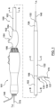
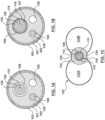
- FIG. 1 illustrates a side view of an occlusion bypassing apparatus 100 in its deployed configuration, with FIG. 1A, FIG. 1B, FIG. 1C being cross-sectional views which are taken at different longitudinal locations along occlusion bypassing apparatus 100 as described in more detail herein.
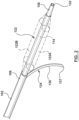
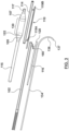
- FIG. 2 is a perspective view of a distal portion of occlusion bypassing apparatus 100 (with the guidewires removed), and FIG. 3 is an exploded view of FIG. 2 .
- Occlusion bypassing apparatus 100 includes an outer shaft component 102 and a balloon 122 for stabilization or anchoring thereof. Outer shaft component 102 will first be described in more detail. Outer shaft component 102 includes a proximal end 104 and a distal end 106.
- Outer shaft component 102 is a tubular or cylindrical element that defines a plurality of lumens formed by multi-lumen profile extrusion. More particularly, outer shaft component 102 includes a needle lumen 109 for housing a needle component 134, a guidewire lumen 129 for housing a tracking guidewire 140, and an inflation lumen 125 for receiving an inflation fluid.
- Proximal end 104 of outer shaft component 102 extends out of the patient and is coupled to a hub 152 of a handle 151.
- Inflation lumen 125 of outer shaft component 102 is in fluid communication with balloon 122 to allow inflation fluid received through hub 152 to be concurrently delivered to both lateral chambers 122A, 122B (see FIG. 2 ) of balloon 122, which will be described in more detail herein.
- hub 152 includes a hemostatic valve 156 to accommodate insertion of occlusion bypassing apparatus 100 and a luer 154 or other type of fitting that may be connected to a source of inflation fluid (not shown) and may be of another construction or configuration without departing from the scope of the present invention.
- outer shaft component 102 has a side port 108 (see FIGS. 24 and 25 ) proximal to distal end 106 thereof.
- Needle lumen 109 includes a curved distal portion that bends from a longitudinal axis of occlusion bypassing apparatus 100 and terminates at side port 108 of outer shaft component 102.
- a needle component 134 is slidably and removably disposed within needle lumen 109. As used herein, "slidably” denotes back and forth movement in a longitudinal direction.
- a curved distal end 136 of needle component 134 is advanced out of side port 108 of outer shaft component 102 towards the true lumen of the vessel.
- curved distal end 136 of needle component 134 is shown extended from side port 108 of outer shaft component 102 in a deployed configuration that is suitable for puncturing the vessel wall to gain access to the true lumen.
- needle component 134 is a tubular or cylindrical component that defines a lumen 135 there-through for slidably receiving a reentry guidewire 170. As shown on FIG. 1 , when reentry guidewire 170 is introduced into occlusion bypassing apparatus 100, reentry guidewire 170 extends proximally from handle 151 and extends distally from a distal tip 137 of needle component 134.
- Guidewire lumen 129 of outer shaft component 102 extends the entire length thereof for accommodating tracking guidewire 140 in a so-called over-the-wire configuration.
- occlusion bypassing apparatus 100 includes a guidewire reinforcement component 110 (see FIG. 1C ).
- Guidewire reinforcement component 110 defines a lumen 112 that is in fluid communication with guidewire lumen 129 of outer shaft component.
- Guidewire reinforcement component 110 distally extends from or beyond distal end 106 of outer shaft component 102.
- a proximal end of guidewire reinforcement component 110 may be disposed adjacent to distal end 106 of outer shaft component 102 and may or may be in direct contact with distal end 106 of outer shaft component 102.
- a build-up tube 114 is disposed over or surrounds guidewire reinforcement component 110.
- a flexible distal tip 126 is bonded or otherwise coupled to a distal end of build-up tube 114.
- Flexible distal tip 126 forms a distal guidewire port 132, as best shown on FIG. 2 .
- the guidewire lumen for occlusion bypassing apparatus 100 is collectively formed via guidewire lumen 129 of outer shaft component 102, lumen 112 of guidewire reinforcement component 110, and distal tip 126 that forms distal guidewire port 132.
- the guidewire lumen for occlusion bypassing apparatus 100 is sized to slidingly receive tracking guidewire 140 so that occlusion bypassing apparatus 100 may be tracked thereover. As shown on FIG.
- tracking guidewire 140 when occlusion bypassing apparatus 100 is tracked over tracking guidewire 140, tracking guidewire 140 extends proximally from handle 151 and extends distally from distal tip 126. Tracking guidewire 140 is omitted from FIG. 2 and FIG. 3 in order to clearly show distal guidewire port 132.
- outer shaft component 102 may be sized to be used with a 5F introducer sheath with lumen 112 of guidewire reinforcement component 110 being sized to accommodate a guidewire having an outer diameter of 0.36 mm. As shown on the cross-sectional FIGS. 1A and FIG.
- outer shaft component 102 is formed as a composite having a reinforcement layer incorporated within a polymeric body in order to enhance strength and/or flexibility and/or torquability. More particularly, outer shaft component 102 may include a braided or reinforcement layer 101 disposed thereover and a polymeric outer or external jacket 103 disposed over reinforcement layer 101. More particularly, outer shaft component 102 may be formed of one or more polymeric materials, non-exhaustive examples of which include polyethylene, polyethylene block amide copolymer (PEBA), polyurethane (PU), polyamide and/or combinations thereof, either laminated, blended or co-extruded.
- PEBA polyethylene block amide copolymer
- PU polyurethane
- Outer shaft component 102 may have a polymer hardness varying in the range of 55 to more than 70 Shore A units, including the variation of the nature of polymer.
- Suitable reinforcement layers for reinforcement layer 101 include braiding, wire mesh layers, embedded axial wires, embedded helical or coiled wires, hypotubes, and the like.
- reinforcement layer 101 surrounds outer shaft component 102 and is a stainless steel braid reinforcement having a PPI (picks per inch of length) ranging between 30 to 80.
- the stiffness or flexibility of reinforcement layer 101 varies along its length such that a continuous variation of PPI results in a gradual variation of stiffness of outer shaft component 102.
- Reinforcement layer 101 may include a stainless steel flat or ribbon wire having the thickness varying in the range 0.0127 mm to 0.127 mm and a width in the range of 0.025 mm to 0.254 mm.
- reinforcement layer 101 may include a round wire with diameter varying in the range of 0.025 mm to 0.127 mm. Further, the number of wires used for reinforcement layer 101 may vary and in one embodiment may range between 8 and 16.
- Outer or external jacket 103 which is disposed over or surrounds reinforcement layer 101, holds down reinforcement layer 101 and provides a smooth outermost.
- Outer jacket 103 may be formed of one or more polymeric materials, non-exhaustive examples of which include polyethylene, polyethylene block amide copolymer (PEBA), polyurethane (PU), polyamide and/or combinations thereof, either laminated, blended or co-extruded. Although described herein as extending the full length of outer shaft component 102, outer jacket 103 and reinforcement layer 101 may extend only over a portion of outer shaft component. In one embodiment, for example, at least a proximal portion of outer shaft component 102 may include outer jacket 103 and reinforcement layer 101.
- outer shaft component 102 may include two inflation lumens that separately deliver inflation fluid to the first and second lateral chambers.
- outer shaft component 102 may include two inflation lumens that separately deliver inflation fluid to the first and second lateral chambers.
- embodiments of outer shaft component 102 are described above with a relatively long guidewire lumen in an over-the-wire configuration, embodiments hereof may be modified to have a rapid-exchange configuration in which the guidewire lumen extends only along a distal portion of the outer shaft component.
- the relatively long guidewire lumen of the above embodiment may be modified to extend only along a distal portion of the outer shaft component and may have a length between 5 cm and 20 cm.
- balloon 122 is formed such that upon inflation balloon 122 includes two lateral chambers 122A, 122B are disposed in parallel on opposing sides of occlusion bypassing apparatus 100.
- Lateral chambers 122A, 122B have a flattened or laterally-extending profile when in an inflated state to anchor occlusion bypassing apparatus 100 within the anatomy, more particularly within the subintimal space of the vessel wall when utilized in the treatment of a CTO, so as to provide stability to occlusion bypassing apparatus 100.
- guidewire reinforcement component 110 distally extends beyond distal end 106 of outer shaft component 102.
- guidewire reinforcement component 110 is a tubular or cylindrical composite element that defines lumen 112 there-through and includes a reinforcement layer 111 and a polymeric body or jacket 113 disposed over reinforcement layer 111.
- Suitable reinforcement layers for layer 111 include braiding via a ribbon or round wire, wire mesh layers, embedded axial wires, embedded helical or coiled wires, hypotubes, and the like.
- Outer jacket 113 may be formed of one or more polymeric materials, non-exhaustive examples of which include polyethylene, polyethylene block amide copolymer (PEBA), polyurethane (PU), polyamide and/or combinations thereof, either laminated, blended or co-extruded.
- reinforcement layer 111 is helical or coiled to prevent kinking and outer jacket 113 is a PI/PTFE composite tube to provide lubricity.
- occlusion bypassing apparatus 100 also includes build-up tube 114 disposed over or surrounding guidewire reinforcement component 110.
- Build-up tube 114 is a tubular or cylindrical element that may be formed of one or more polymeric materials, non-exhaustive examples of which include polyethylene, polyethylene block amide copolymer (PEBA), polyurethane (PU), polyamide and/or combinations thereof, either laminated, blended or co-extruded.
- PEBA polyethylene block amide copolymer
- PU polyurethane
- Build-up tube 114 functions to embed or cover guidewire reinforcement component 110, and also provides a substrate for bonding or otherwise attaching balloon 122.
- Build-up tube 114 ends in within distal tip 126, which is bonded thereto.
- balloon 122 includes a body portion 130, an elongated proximal neck 115, a distal neck 117, a proximal cone 105, and a distal cone 107.
- body portion 130 has a length that ranges between 9 mm and 13 mm
- distal neck 117 has a length that ranges between 5 mm and 7 mm
- elongated proximal neck length has a length that ranges between 30 mm to 36 mm.
- body portion 130 of balloon 122 forms or includes lateral chambers 122A, 122B of balloon 122 as will be described in more detail herein with respect to FIGS. 4-5 .
- Proximal cone 105 extends between elongated proximal neck 115 and body portion 130 of balloon 122, while distal cone 107 extends between distal neck 117 and body portion 130 of balloon 122 such that body portion 130 of balloon 122 extends between or is sandwiched elongated proximal neck 115 and a distal neck 117.
- distal cone 107 extends at a 30 degree angle relative to the longitudinal axis of occlusion bypassing apparatus 100 and proximal cone 105 extends at a 40 degree angle relative to the longitudinal axis of occlusion bypassing apparatus 100.
- the relative angles of the proximal and distal cones may be differentiated to accomplish distally, a smoother transition to distal tip 126 using a 30 degrees distal cone 107, and proximally to minimize the distance in between outer shaft component 102 and body portion 130 of balloon 122 with 40 or more degrees.
- elongated proximal neck 117 of balloon 122 When assembled into occlusion bypassing apparatus 100, elongated proximal neck 117 of balloon 122 is disposed over and bonded to outer shaft component 102 such that elongated proximal neck 117 is disposed or spans over both proximal and distal to side port 108 of the outer shaft component.
- Body portion 130 (and lateral chambers 122A, 122B thereof) are disposed distal to distal end 106 of outer shaft component and may be considered as forming the distal end of occlusion bypassing apparatus 100.
- Distal neck 117 of balloon 122 is disposed over and bonded to build-up tube 114. As best shown on FIG.
- build-up tube 114 and guidewire reinforcement component 110 disposed there-through extend through body portion 130 of balloon 122, with lateral chambers 122A, 122B disposed in parallel on opposing sides of build-up tube 114 upon inflation of balloon 122.
- Body portion 130 of balloon 122 thus has a flattened profile in an inflated state due to lateral chambers 122A, 122B that laterally extend from opposing sides of build-up tube 114 for stabilizing occlusion bypassing apparatus 100 within a subintimal space.
- FIG. 4 is a schematic top view of the distal portion of the occlusion bypassing apparatus 100 with the guidewires removed.
- FIG. 5 is a schematic top view of the distal portion of the occlusion bypassing apparatus 100 with a mandrel 144 inserted therethrough to illustrate a manufacturing step of balloon 122.
- at least one weld 124 extends over body portion 130 of balloon 122.
- two welds 124 extend over opposing sides of body portion 130 of balloon 122 to form lateral chambers 122A, 122B thereof.
- Balloon 122 originates from a regular or known cylindrical balloon used for balloon angioplasty, i.e., a POBA or plain old balloon angioplasty balloon.
- a single cylindrical POBA balloon is positioned over build-up tube 114 such that the balloon circumferentially surrounds build-up tube 114.
- the single cylindrical POBA balloon is laser welded to modify its shape to thereby form balloon 122.
- a fillet weld 124 is disposed over body portion 130 of balloon 122 to.
- a second fillet weld 124 is disposed over the opposing side of body portion 130 as well.
- mandrel 144 may be positioned through lumen 112 of guidewire reinforcement component 110 and an inflation fluid (represented by directional arrow 131) is delivered as shown in FIG. 5 .
- Fillet welds 124 create a flat or flattened balloon profile with the top and bottom opposing sides of balloon 122 being attached or constrained to build-up tube 114 while the left and right opposing sides of balloon 122 are not attached or constrained to build-up tube 114.
- fillet welds 124 extend over the entire length of body portion 130 but do not extend over proximal and distal cones 105, 107, respectively.
- balloon 122 When inflated, the top and bottom sides of balloon 122 that are attached or constrained to build-up tube 114 remain fixed while the left and right sides of balloon 122 that are not attached or constrained to build-up tube 114 expand or inflate in opposing lateral directions away from build-up tube 114 to thereby form lateral chambers 122A, 122B. Lateral chambers 122A, 122B are in fluid communication with each other.
- balloon 122 When deflated, balloon 122 has a circular profile that conforms to build-up tube 114 for maneuvering occlusion bypassing apparatus 100 through a vasculature.
- Occlusion bypassing apparatus 100 may include radiopaque markers in order to visually monitor the location of the apparatus in situ as well as the orientation of the apparatus. Each marker has an individual function or advantage, and collectively, the relative positioning of the multiple markers may be utilized to detect device orientation.
- cylindrical or ring first and second radiopaque markers 119A, 119B provide visibility of balloon 122 and thus assist in properly positioned the occlusion bypassing apparatus (balloon and outer shaft component are shown in phantom in FIGS. 9-10 so that the components internal thereto are clearly shown).
- Markers 119A, 119B may be coupled to an annular lumen of the occlusion bypassing apparatus, such as the guidewire lumen.
- markers 119A, 119 are positioned over guidewire reinforcement component 110 to mark or indicate body portion 130 of balloon 122.
- Markers 119A, 119B are positioned adjacent to proximal and distal cones 105, 107, respectively, of balloon 122.
- Markers 119A, 119B indicate or mark the proximal and distal ends of body portion 130 of the balloon in order to provide the user with information about balloon position.
- Marker 119B is also positioned adjacent to distal tip 126 of occlusion bypassing apparatus 100, and thus further provides visibility of the distal end of the apparatus during delivery and advancement thereof.
- marker 119A functions to mark the maximum axial extension of the needle component when deployed. More particularly, marker 119A provides the user with information about the vessel portion that is potentially subject to contact the needle component when deployed.
- Radiopaque marker 160 which may be considered a third radiopaque marker, allows a user to properly position occlusion bypassing apparatus 100 across an occlusion or lesion in situ and unequivocally identify the position of side port 108.
- FIG. 6 illustrates a perspective view of marker 160.
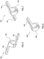
- Marker 160 is an asymmetrical, S-shaped radiopaque marker that may be coupled to a distal portion of a needle housing 116, which will be described in more detail herein.
- Marker 160 includes an annular or ring portion 180, a first leg portion 182, and a second leg portion 184. Leg portions 182, 184 extend from opposing sides of ring portion 180 and are 180 degrees offset from each other. As shown in the side and top views of FIG. 9 and FIG.
- marker 160 has a unique and distinctive shape depending upon the orientation of the occlusion bypassing apparatus. Due to the unique and asymmetrical shape of marker 160, marker 160 allows a user to properly position the occlusion bypassing apparatus across an occlusion or lesion in situ and unequivocally identify the position and orientation of the side port.
- markers 119A, 119B, 160 may be formed with different shapes, different dimensions, and/or different materials having different levels of radiopacity so that they may be distinguished from each other when in situ.
- Radiopaque markers 119A, 119B, 160 may be formed from Platinum-Iridium alloys, gold, tantalum, and/or loaded polymeric materials.
- FIG. 7 illustrates another configuration of a radiopaque marker 760 that may be used in embodiments herein.
- Marker 760 may be coupled to a distal portion of needle housing 116.
- Marker 760 is generally T-shaped and includes an annular or ring portion 780, a first leg portion 782, and a second leg portion 784.
- Leg portions 782, 784 extend from opposing sides of ring portion 780 but are not circumferentially offset from each other.
- marker 760 Due to its asymmetry, marker 760 has a unique and distinctive shape depending upon the orientation of the occlusion bypassing apparatus. Due to the unique shape of marker 760, marker 760 allows a user to properly position the occlusion bypassing apparatus across an occlusion or lesion in situ and unequivocally identify the position and orientation of the side port. Additional marker configurations may also be used in embodiments described herein, including but not limited to an L-shaped radiopaque marker 860 shown in FIG. 8 . Marker 860 may be coupled to a distal portion of needle housing 116. Marker 860 includes an annular or ring portion 880 and a leg portion 882 extending from one end thereof.
- marker 860 Due to its asymmetry, marker 860 has a unique and distinctive shape depending upon the orientation of the occlusion bypassing apparatus. Due to the unique shape of marker 860, marker 860 allows a user to properly position the occlusion bypassing apparatus across an occlusion or lesion in situ and unequivocally identify the position and orientation of the side port.
- Needle lumen 109 of outer shaft component 102 houses needle housing 116. More particularly, needle housing 116 lays within needle lumen 109 of outer shaft component 102, or stated another way is disposed within a distal portion of needle lumen 109 of outer shaft component 102. Accordingly, with reference back to FIG. 1 , FIG. 1A is a cross-sectional view taken along line A-A of FIG. 1 that shows needle component 134 within needle lumen 109, while FIG. 18 is a cross-sectional view taken along line B-B of FIG. 1 (which is taken at a more distal longitudinal location along occlusion bypassing apparatus 100) that shows needle component 134 within needle housing 116.
- Needle housing 116 is a tubular or cylindrical shaft component that is disposed at the distal portion of needle lumen 109, with a proximal end thereof (i.e., the two proximal-most tabs thereof) being embedded into the polymeric material of outer shaft component 102. Needle housing 116 defines a lumen sized and configured to slidably and removably receive needle component 134 there-through. When needle component 134 is positioned within occlusion bypassing apparatus 100, needle component 134 is disposed or extends through needle lumen 109 of outer shaft component 102 and through lumen 127 (see FIG. 1B ) of needle housing 116.
- needle housing 116 is a metallic tube of a relatively short length. Typically, the needle housing length is about 2-5% of the needle lumen length. Needle housing 116 is preferably formed from a shape memory material such as nitinol to ensure high flexibility of occlusion bypassing apparatus 100 during advancement through the vasculature. Alternatively, needle housing 116 may be formed from a metallic resilient material such as steel or spring temper stainless steel.
- needle housing 116 includes a proximal transition portion 118 with a variable flexibility and a curved distal portion 120 that bends from the longitudinal axis L A of occlusion bypassing apparatus 100.
- FIG. 11 is a side view of needle housing 116, wherein the needle housing is removed from occlusion bypassing apparatus 100 for illustrative purposes only.
- FIG. 12 is a top view of needle housing 116.
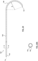
- Curved distal portion 120 includes a pre-formed or pre-shaped bend or curve. A heat or thermal treatment of the selected material of needle housing 116 may be used to set the shape of curved distal portion 120. More particularly, as shown in FIG.
- curved distal portion 120 extends, bends, or otherwise curves in a circular path while the remaining length of needle housing 116 is straight and extends parallel to the longitudinal axis L A of occlusion bypassing apparatus 100.
- curved distal portion 120 extends in a circular path and forms a portion of a circle having a radius R.
- radius R is 5 mm.
- radius R is in the range from 4 mm to 8 mm.
- distal portion 120 of needle housing 116 terminates at side port 108 of outer shaft component 102
- the curved distal portion 120 of needle housing 116 functions as a guide to direct needle component 134 through side port 108 such that needle component 134 exits occlusion bypassing apparatus 100 in a stable configuration at a desired orientation for re-entry into a true lumen.
- a distal end of curved distal portion 120 is angulated with respect to the longitudinal axis L A of occlusion bypassing apparatus 100.
- the distal end of curved portion 120 is angled at an angle of 10° with respect to the longitudinal axis L A of occlusion bypassing apparatus 100.
- a distal end of curved distal portion 120 is straight or parallel to the longitudinal axis L A of occlusion bypassing apparatus 100.
- needle housing 116 includes proximal transition portion 118.
- Transition portion 118 has a variable flexibility along its length that decreases in a distal direction as indicated by directional arrow 121 (see FIG. 11 ). Since the flexibility of transition portion 118 decreases in a distal direction, the transition portion allows for a gradual modulation of the flexibility between the flexible needle lumen 109 (located proximal to transition portion 118) and relatively less flexible, or rigid, remaining length of needle housing 116 (located distal to transition portion 118).
- occlusion bypassing apparatus 100 corresponds to the flexibility of needle housing 116, with occlusion bypassing apparatus 100 being more flexible proximal to needle housing 116 and less flexible along needle housing 116. Transition portion 118 similarly will provide occlusion bypassing apparatus 100 with a variable flexibility along its length that decreases in a distal direction.
- transition portion 118 includes a plurality of apertures 142, wherein pairs of apertures align with each other along a respective transverse axis of needle housing 116.
- Each aperture is a cut-out portion or window that increases the flexibility of transition portion 118 as compared to the remaining length of needle housing 118, i.e., straightening portion 123 of needle housing 116 and curved distal portion 120 which have no apertures or cut-out portions formed therein.
- any respective pair of aligned apertures may be referred to singularly or collectively as a pair or pairs of aligned apertures 142.
- each aperture in a pair of aligned apertures 142 has an hourglass shape and is disposed from the other aperture of the pair on an opposite side of the perimeter or outer surface of needle housing 116 so as to be diametrically opposed thereto.
- the pitch or spacing between adjacent pairs of aligned apertures increases in a distal direction.
- the distance or spacing between adjacent pairs of aligned apertures 142 continues to increase such that distance or spacing between the most distal apertures is the greatest. Since a greater amount of metallic material extends between consecutive pairs of aligned apertures 142, gradually increasing the pitch or spacing between axially adjacent pairs of aligned apertures 142 in the distal direction results in a gradual decrease of flexibility in the distal direction.
- the size or area of adjacent pairs of aligned apertures 142 may be varied in order to result in a gradual decrease of flexibility along the length of transition portion 118 in the distal direction as further described in U.S. Patent Application 14/460,068 to Guala et al, filed 8/14/2014 (Attorney Docket No. C00007385 USU1).
- FIG. 13 is an enlarged perspective view of a distal tip of needle housing 116. More particularly, in order to improve embedding of needle housing 116 within outer shaft component 102, a small opening or skive cut 128 is formed at the very distal tip of curved distal end 120. Skive cut 128 grabs or embeds into the polymeric material of outer shaft component 102 and/or elongated proximal neck 115 of balloon 122 which encapsulates needle housing 116 within occlusion bypassing apparatus 100 to aid in securing needle housing 116 within outer shaft component 102.
- FIG. 14 is a side view of a needle housing 1416 according to another embodiment hereof, wherein the needle housing is removed from an occlusion bypassing apparatus for illustrative purposes only.
- FIG. 15 is a top view of needle housing 1416.
- Needle housing 1416 has a curved distal portion 1420 which is similar to curved distal portion 120.
- a proximal portion of needle housing 1416 includes a tab 1439 formed by a skive cut which has a variable flexibility along its length that decreases in a distal direction.
- tab 1439 is more flexible that the remaining length of needle housing 1416 i.e., straightening portion 1423 of needle housing 1416 and curved distal portion 1420 which have no cut-out portions formed therein.
- a width of tab 1418 increases along its length such that a distal end thereof is wider than a proximal end thereof.
- At least a portion of tab 1439 is configured to be embedded into the polymeric material of outer shaft component 102. In an embodiment, the entire length of tab 1439 is embedded into the polymeric material of outer shaft component 102. Further, tab 1439 provides proper orientation of the exit port of needle housing 1417 during assembly of the needle housing into the outer shaft component.
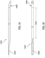
- FIG. 16 is a side view of a needle housing 1616 according to another embodiment hereof, wherein the needle housing is removed from an occlusion bypassing apparatus for illustrative purposes only.
- FIG. 17 is a top view of needle housing 1616.
- Needle housing 1616 has a curved distal portion 1620 which is similar to curved distal portion 120.
- a proximal portion of needle housing 1616 includes an expandable stent 1618 which is more flexible that the remaining length of needle housing 1616 i.e., straightening portion 1623 of needle housing 116 and curved distal portion 1620 which have no apertures or cut-out portions formed therein.
- Stent 1618 is self-expanding and is configured to expand into apposition with the polymeric material of outer shaft component 102. More particularly, stent 1618 is a tubular frame or scaffold that defines a plurality of diamond or kite-shaped openings, with each diamond-shaped opening being defined by four vertexes or vertices and four segments or struts extending or formed between vertexes. In this embodiment, stent 1618 has a lattice or mesh configuration which is laser cut from a tube and is formed as a unitary structure or component.
- stent 1618 may be made from stainless steel, a pseudo-elastic metal such as a nickel titanium alloy or Nitinol, or a so-called super alloy, which may have a base metal of nickel, cobalt, chromium, or other metal.
- a pseudo-elastic metal such as a nickel titanium alloy or Nitinol
- super alloy which may have a base metal of nickel, cobalt, chromium, or other metal.
- FIG. 18 is a side view of a needle housing 1816 according to another embodiment hereof, wherein the needle housing is removed from an occlusion bypassing apparatus for illustrative purposes only.
- FIG. 19 is a top view of needle housing 1816.
- Needle housing 1816 has a curved distal portion 1820 which is similar to curved distal portion 120.
- a proximal portion of needle housing 1816 includes an expandable stent 1818 which is more flexible that the remaining length of needle housing 1816 i.e., straightening portion 1823 of needle housing 1816 and curved distal portion 1820 which have no apertures or cut-out portions formed therein.
- Stent 1818 is a tubular frame or scaffold that defines a plurality of diamond or kite-shaped openings, with each diamond-shaped opening being defined by four vertexes or vertices and four segments or struts extending or formed between vertexes.
- stent 1818 has a lattice or mesh configuration which is laser cut from a tube and is formed as a unitary structure or component.
- Stent 1818 is self-expanding and may be made from stainless steel, a pseudo-elastic metal such as a nickel titanium alloy or Nitinol, or a so-called super alloy, which may have a base metal of nickel, cobalt, chromium, or other metal.
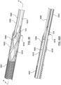
- stent 1818 is sized and configured to embrace or surround an outer surface of the outer shaft component. More particularly, as shown in FIGS. 44, 44A , and 45 , stent 1818 becomes the distal end of a braided or reinforcement layer 1801 disposed over an outer shaft component 1802 and a polymeric external jacket (such as external jacket 103 described herein but not shown in FIGS. 44, 44A , and 45 for purposes of clarity) is over-molded onto stent 1818 to secure or attach stent 1818 and needle housing 1816 to outer shaft component 1802.
- a polymeric external jacket such as external jacket 103 described herein but not shown in FIGS. 44, 44A , and 45 for purposes of clarity
- needle housing 1816 i.e., straightening portion 1823 of needle housing 1816 and curved distal portion 1820 which have no apertures or cut-out portions formed aligns with a needle lumen 1809 of outer shaft component 1802 so stent 1818 is eccentric with respect to straightening portion 1823 of needle housing 1816 and curved distal portion 1820.
- needle component 134 which defines lumen 135 for receiving reentry guidewire 170 as described herein
- needle component 134 is slidingly disposed through aligned needle lumen 1809 of outer shaft component 1802 and the remaining length of needle housing 1816, i.e., straightening portion 1823 of needle housing 1816 and curved distal portion 1820.
- a distal end 1806 of outer shaft component 1802 terminates within stent 1818 and thus the occlusion bypassing system includes a first connection shaft 1886 which extends within a distal portion of a guidewire lumen 1840 and distally extends beyond distal end 1806 of outer shaft component 1802 to bridge or connect the guidewire lumen of the outer shaft component to a guidewire reinforcement component (such as guidewire reinforcement component 110 described herein but not shown in FIGS.
- a guidewire reinforcement component such as guidewire reinforcement component 110 described herein but not shown in FIGS.
- First and second connection shafts 1886, 1888 may be formed of poli-imide or other suitable polymeric materials.
- Needle component 134 which is shown removed from occlusion bypassing apparatus 100 in FIG. 20 , is a tubular or cylindrical element that is configured to be slidably disposed within lumens 109, 127 of outer shaft component 102, needle housing 116, respectively, and removable therefrom. More particularly, needle component 134 is disposed within outer shaft component 102 and needle housing 116 such that there is sufficient space or room therebetween for needle component 134 to be movable or slidable in a longitudinal direction relative to outer shaft component 102 and needle housing 116.
- needle component 134 may be a hypotube that defines a lumen 135 there-through as shown in the cross-sectional view of FIG. 20A .
- lumen 135 of needle component 134 is sized to accommodate a guidewire having an outer diameter equal to or less than 0.36 mm such that occlusion bypassing apparatus 100 has a low profile.
- a proximal end of needle component 134 is housed within handle 151 and distal tip 137 of needle component 134 is configured to pierce or penetrate through a wall of a vessel when extended or deployed.
- Needle component 134 includes an elongated first or proximal segment 138 that extends substantially parallel with longitudinal axis L A of occlusion bypassing apparatus 100 and curved distal end 136 distally extending from a distal end of proximal segment 138.
- Curved distal end 136 is pre-formed in a bent or curved shape or configuration. More particularly, as shown in FIG. 20 , curved distal end 136 extends, bends, or otherwise curves in a circular path. In an embodiment hereof, curved distal end 136 extends in a circular path approximately 160° from a distal end of proximal segment 138, thereby forming a portion of a circle having a radius R.
- At least curved distal end 136 of needle component 134 is formed from a biocompatible resilient metal such as spring temper stainless steel or nitinol, which utilizes the elastic properties of stress induced martensite, such that a heat or thermal treatment of the selected material may be used to set the shape of curved distal end 136.
- needle component 134 may be formed from more than one material, for e.g., with proximal segment 138 being formed of stainless steel and only curved distal end 136 being formed of nitinol.
- curved distal portion 120 of needle housing 116 is formed with the same curvature as curved distal end 136 of needle component 134 so that an automatic centering design is obtained. More particularly, curved distal portion 120 of needle housing 116 includes a bend or turn that corresponds with, matches or is the same as the bend or turn of curved distal end 136 of needle component 134. The bend of curved distal portion 120 of needle housing 116 is formed with the same radius R as the bend of curved distal end 136 of needle component 134 so that the needle component 134 exits side port 108 of outer shaft component 102 at or with the correct orientation for re-entry of a true lumen of a vessel.
- needle component 134 is very stable inside needle housing 116, thus minimizing any rotation or relative movement between the two components, especially during the needle deployment.
- the needle component may include a straight segment disposed between the curved distal end and the distal tip. More particularly, FIG. 21 is a side view of a distal portion of a needle component 2134 according to another embodiment hereof, wherein the needle component includes a straight segment 2145 disposed between curved distal end 2136 and distal tip 2137.
- Straight segment 2145 may range between 1 and 3 mm in length, and functions to improve the angulation of reentry guidewire 170 into the vessel true lumen. Stated another way, straight segment 2145 improves the direction of reentry guidewire 170 so that reentry guidewire 170 exits from needle component 134 and is directed distal of the occlusion rather than being directed backward toward the occlusion.
- the needle component may include a radiopaque marker to improve visibility thereof and allow a user to visually check and then correctly track the deployment of the needle component.
- FIG. 22 is a side view of a distal portion of a needle component 2234 according to another embodiment hereof, wherein the needle component includes an encapsulated radiopaque marker 2243 proximal to distal tip 2237 thereof.
- marker 2243 is a small gold pill can be inserted within a recess formed on an outer surface of needle component 2234.
- Radiopaque coating 2343 is a thin layer of material and may be formed by sputtering, dipping, or other suitable process.
- needle housing 116 in a first or delivery configuration of the apparatus the curved distal end 136 of needle component 134 is held or restrained in a straightened form within needle housing 116.
- Balloon 122 and inflation lumen 125 are not shown in FIG. 24 since the sectional view is taken approximately through the midline of occlusion bypassing apparatus 100 and proximal to distal end 106 of outer shaft component 102.
- Needle housing 116 is formed from a relatively stiff or less flexible material as described above in order to effectively straighten curved distal end 136 of needle component 134.
- needle component 134 is pre-loaded within occlusion bypassing apparatus 100 and curved distal end 136 of needle component 134 is held or restrained in a straightened form within straightening portion 123 of needle housing 116 which has no apertures or cut-out portions formed therein. Since needle housing 116 is formed with varying flexibility, straightening portion 123 of needle housing 116 with no apertures or cut-out portions is relatively stiffer or less flexible to ensure straightening of curved distal end 136 of needle component 134. Straightening portion 123 of needle housing 116 holds the curved distal end of the needle component in a straightened form during advancement of occlusion bypassing apparatus 100 in the human vasculature.
- curved distal end 136 of needle component 134 extends from side port 108 of outer shaft component 102 and bends or curves from longitudinal axis L A of the apparatus.
- Balloon 122 and inflation lumen 125 are not shown in FIG. 24 since the sectional view is taken approximately through the midline of occlusion bypassing apparatus 100 and proximal to distal end 106 of outer shaft component 102. More particularly, when it is desired to distally advance needle component 134 through side port 108 of outer shaft component 102, it must first be confirmed that side port 108 is positioned beyond or distal to the target occlusion and is oriented in the direction of the true lumen of the vessel.
- occlusion bypassing apparatus may be monitored via radiopaque markers 119A, 119B, 160 of apparatus 100 described above.
- needle component 134 is distally advanced relative to outer shaft component 102 such that curved distal end 136 is no longer constrained by needle housing 116 but rather is extended to protrude from side port 108 of outer shaft component 102.
- curved distal end 136 resumes its pre-formed shape or geometry by its own internal restoring forces.
- curved distal end 136 extends, bends, or otherwise curves in a circular path, thereby forming a portion of a circle having a radius R.
- distal tip 137 may be used to penetrate through the vessel wall and re-enter a true lumen of a vessel as described herein.
- distal tip 137 may be used to penetrate through the vessel wall and re-enter a true lumen of a vessel as described herein.
- Balloon 122 may be expanded or inflated to anchor outer shaft component 102 within a subintimal tract either before or after the distal advancement of needle component 134.
- the physician's experience during the procedure he may realize that the subintimal space is sufficiently narrow and suitably envelops the occlusion bypassing apparatus that the latter is properly anchored within the subintimal space. Therefore, in this case there could be no need for expanding the balloon.
- Occlusion bypassing apparatus 100 may have handle 151 coupled thereto in order to assist in the manipulation of needle component 134 and outer shaft component 102.
- handle 151 includes a knob or cogwheel 153 and a slider 155.
- FIG. 26 is a perspective view of handle 151 with guidewires 140, 170 removed
- FIG. 27 is a sectional perspective view of handle 151 with guidewires 140, 170 removed.
- Hub 152 extends between knob 153 and outer shaft component 102.
- Knob 153 is coupled to outer shaft component 102 such that rotation of the knob results in rotation of the outer shaft, as well as any components attached thereto or incorporated therein such as needle housing 116.
- Handle 151 also includes a tubular component 2761 (shown in FIG. 27 ) that houses needle component 134 within the handle in order to prevent kinking of the needle component. Further, handle 151 also includes a flushing luer 2663 (shown in FIG.
- occlusion bypassing apparatus 100 may be flushed prior to use within the vasculature in accordance with techniques known in the field of interventional cardiology and/or interventional radiology. Flushing of occlusion bypassing apparatus 100 is described in more detail herein.
- FIG. 28 is an enlarged perspective view of a proximal end of handle 151
- FIG. 29 is an enlarged perspective view of the distal portion of the occlusion bypassing apparatus 100.
- flushing luer 1663 is configured to permit exit of both tracking guidewire 140 and reentry guidewire 170 from the proximal end of handle 151.
- tracking guidewire 140 exits from distal tip 126 of occlusion bypassing apparatus 100 while reentry guidewire 170 exits from distal tip 137 of needle component 134.
- the flushing luer may be configured to only permit exit of reentry guidewire 170 and tracking guidewire 140 may exit distal to handle 151.
- FIG. 30 is an enlarged perspective view of a hub 3052 that may be utilized in embodiments hereof, wherein the hub has an exit port 3058 formed therein.
- tracking guidewire 140 used to track occlusion bypassing apparatus 100 through the vasculature is intended to exit before handle 3051.
- Exit port 3058 is a dedicated recess drawn within hub 3052 which bridges or extends between handle 3051 and the outer shaft component (not shown in FIG. 30 ).
- FIG. 31 is an enlarged perspective view of a hub 3152 that includes a bail-out feature so that the hub may be disengaged or disconnected from the handle.
- a bail-out feature may be useful where, for any reasons, the handle and/or the apparatus fails such as but not limited to when retraction of needle component 134 cannot be accomplished.
- handle 3151 allows detachment of hub 3152 that bridges or extends between handle 3151 and the outer shaft component (not shown in FIG. 31 ).
- Hub 3152 includes threads 3168 that mate with helical recesses 3166 formed within a knob 3153 of handle 3151 to allow for separation or detachment of handle 3151 from occlusion bypassing apparatus 100.
- FIG. 31 illustrates handle 3151 while separating from hub 3152.
- handle 3151 may be detachably coupled to hub 1352 via other coupling features like detachable bonds or adhesives.
- FIG. 32 is a side sectional view of a slider 3255 that may be utilized in embodiments hereof, wherein the slider includes a built-in safety mechanism.
- handle 3251 includes a safety blockage of slider 3255 to prevent unintended needle deployment while tracking through the vasculature.
- Slider 3255 includes a radial extension or tab 3278 on an underside surface thereof that engages or is received into a recess 3276 formed on a housing or shell of handle 3251.
- Tab 3278 secures slider 3255 in a locked position until the user exerts a force onto slider 3255 to disengage tab 3278 from recess 3276 when deployment of needle component 134 is desired.
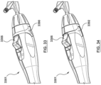
- FIGS. 33-34 illustrate another handle feature that may be utilized in embodiments hereof. More particularly, handle 3351 is configured to permit a two-stage needle deployment if desired. Handle 3351 includes a removable stopper 3390 built into the housing or shell of handle 3351. Stopper 3351 is shown positioned on handle 3351 in FIG. 33 , thus resulting in standard needle deployment depth, and stopper 3351 is shown removed from handle 3351 in FIG. 34 , thus resulting in additional or extra needle deployment depth. Stopper 3390 is loaded or positioned onto handle 3351 during assembly or packaging of the apparatus. When stopper 3390 is positioned on handle 3351 as shown in FIG. 33 , occlusion bypassing apparatus 100 is configured for a standard needle deployment depth of approximately 5-6 mm.
- occlusion bypassing apparatus 100 When stopper 3390 is removed as shown in FIG. 34 , slider 3355 and needle component 134 may be further distally advanced and thus occlusion bypassing apparatus 100 is configured for an extra 3 mm needle deployment depth such that the total needle deployment depth is 8-9 mm.
- the extra needle deployment depth may be desirable depending upon application.
- occlusion bypassing apparatus 100 may be designed or configured for treatment within a peripheral vasculature for use in SFA and Popliteal arteries. However, since from proximal SFA to distal popliteal the trunk size of the artery narrows down of some millimeters, the extra 3 mm needle deployment depth is designed to cover this gap.
- Stopper 3390 may be removed after needle component 134 is deployed the standard deployment depth and it is determined that additional or extra depth is desired. Stopper 3390 thus permits either a single-step needle deployment when the standard deployment depth is sufficient (and thus stopper 3390 is not required to be removed), or a two-step needle deployment when additional or extra depth is desired (and thus stopper 3390 is removed following the first step of needle deployment to the standard deployment depth).
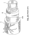
- FIG. 35 is a sectional view of the anatomy of an artery wall, which for purposes of this description is shown to consist essentially of three layers, the tunica intima I ("intima”), tunica media M ("media”) which is the thickest layer of the wall, and the tunica adventitia A (“adventitia”).
- intima the tunica intima I
- media M the thickest layer of the wall
- tunica adventitia A adventitia”
- an internal elastic membrane IEM is disposed between the media M and adventitia A.
- the adventitia A is made of collagen, vasa vasorum and nerve cells
- the media M is made of smooth muscle cells
- the intima I is made up of a single layer of endothelial cells that provide a nonthrombogenic surface for flowing blood.
- Occlusion bypassing apparatus 100 is used as part of a system for creating a subintimal reentry tract within a wall of a blood vessel V to allow blood flow around an occlusion.
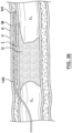
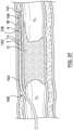
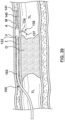
- FIGS. 36-43 illustrate an exemplary method of using the above-described occlusion bypassing apparatus 100 to bypass a chronic total occlusion (CTO) according to an embodiment hereof.
- CTO chronic total occlusion
- occlusion bypassing apparatus 100 Prior to use of occlusion bypassing apparatus 100 within the vasculature, it may be desirable to flush the apparatus in accordance with techniques known in the field of interventional cardiology and/or interventional radiology. Flushing of occlusion bypassing apparatus 100 may be performed through lumen 135 of needle component 134. More particularly, small openings or holes (not shown) may be provided on needle component 134.
- side port 108 of outer shaft component 102 is occluded. Saline solution is introduced into a proximal end of lumen 135 of needle component 134 and flushes lumen 135. Since side port 108 is occluded, the saline solution exits from the small holes formed on needle component 134 and flushes needle lumen 109 of outer shaft component and lumen 127 of needle housing 116.
- tracking guidewire 140 having a distal end 141 is transluminally advanced through the vasculature to a position upstream of a treatment site, which in this instance is shown as occlusion O within a true lumen TL of blood vessel V.
- Tracking guidewire 140 pierces the intima I and is advanced distally to create a subintimal tract by locally dissecting or delaminating intima I from media M or by burrowing through media M.
- a clinician may manipulate distal end 141 of tracking guidewire 140 by prolapsing or bending-over the distal end of tracking guidewire 140 (not shown) and thereafter may use the stiffer arc or loop of the prolapsed distal end to pierce into the intima I to advance tracking guidewire 140 there through.
- the piercing of the intima I is aided by the fact that typically blood vessel V is diseased, which in some instances makes the intima I prone to piercing.
- Tracking guidewire 140 is distally advanced within the subintimal tract from a near side of occlusion O to a position where distal end 141 thereof is positioned in the subintimal tract on a far side of occlusion O.
- another device other than tracking guidewire 140 initially may be used to create the subintimal tract.
- a guidewire other than tracking guidewire 140 may be utilized to create the subintimal tract. More particularly, a guidewire having a relatively larger outer diameter than tracking guidewire 140, such as between 0.812-1.016 mm, may be utilized to create the subintimal tract because a larger guidewire has greater column strength to gain access to the subintimal space of vessel V. If an alternative device is used instead of tracking guidewire 140 to form the subintimal tract, such alternative device may be removed and replaced with tracking guidewire 140 after the subintimal tract has been formed.
- occlusion bypassing apparatus 100 may be tracked over guidewire 140 and advanced such that distal tip 126 is adjacent to the far or downstream end of occlusion O as shown in FIG. 37 .
- needle component 134 is pre-loaded within occlusion bypassing apparatus 100.
- curved distal end 136 of needle component 134 is held or restrained in a straightened form within needle housing 116 as described above.
- needle component 134 is not positioned or disposed within occlusion bypassing apparatus 100 when occlusion bypassing apparatus 100 is initially advanced over guidewire 140 but rather is subsequently introduced into the apparatus.
- occlusion bypassing apparatus 100 should be positioned and oriented such that side port 108 of outer shaft component 102 is positioned beyond or distal to the target occlusion and is oriented in the direction of the true lumen of the vessel.
- FIG. 38A illustrates a cross-sectional view of apparatus 100 within a vessel V having a true lumen TL and a subintimal space SS.
- the subintimal space SS may be described as having an arc, curve, or C shape.
- lateral chambers 122A, 122B of balloon 122 expand into contact with the surrounding patient's anatomy to fill out or occupy the subintimal space SS to improve anchoring and to minimize damage to the surrounding anatomy.
- balloon 122 is described herein for providing stabilization during distal advancement or deployment of needle component 134, in another embodiment hereof (not shown) inflation of balloon 122 may also be used to create or assist in creating the subintimal tract. In such an embodiment, balloon 122 may be inflated multiple times in the subintima to initially support delivery of the occlusion bypassing apparatus across the lesion within the subintima and then subsequently during a re-entry procedure.
- needle component 134 is then deployed through side port 108 of occlusion bypassing apparatus 100. Needle component 134 is distally advanced relative to outer shaft component 102 and needle housing 116 until curved distal end 136 extends from or protrudes out of side port 108 of outer shaft component 102 such that distal tip 137 of the needle component penetrates the intima to gain access to the true lumen of the vessel distal to, i.e., downstream of, the CTO.
- needle component 134 is distally advanced relative to outer shaft component 102 (as well as needle housing 116 housed within outer shaft component 102) such that curved distal end 136 is no longer constrained by needle housing 116 but rather is extended to protrude from side port 108 of outer shaft component 102.
- curved distal end 136 resumes its pre-formed shape or geometry by its own internal restoring forces.
- curved distal end 136 extends, bends, or otherwise curves in a circular path, thereby forming a portion of a circle having a radius R.
- distal tip 137 may be used to penetrate through the vessel wall and re-enter a true lumen of a vessel.
- distal tip 137 may be used to penetrate through the vessel wall and re-enter a true lumen of a vessel.
- Reentry guidewire 170 may be advanced through lumen 135 of needle component 134 and into the true lumen TL of vessel V as shown in FIG. 40 .
- Reentry guidewire 170 has a relatively smaller outer diameter such as 0.356 mm in order to minimize the size of needle component 134 and subsequently, minimize the size of occlusion bypassing apparatus 100.
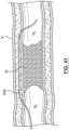
- occlusion bypassing apparatus 100 may be removed and reentry guidewire 170 may be left in place as shown in FIG. 41 , with reentry guidewire 170 extending in true lumen TL proximal to the CTO, through the subintimal tract, and back into true lumen TL distal to the CTO such that the CTO may now be successfully crossed via the pathway or conduit thus created.
- a covered or uncovered stent may be delivered over reentry guidewire 170 and implanted within the subintimal tract to facilitate flow from the lumen of the vessel upstream of the CTO, through the subintimal tract and back into the lumen of the vessel downstream of the CTO.
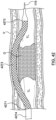
- FIG. 42 shows a distal end of a catheter 4274 having a stent 4272 mounted thereon being advanced over reentry guidewire 170 to a position where a distal end 4273 of the radially collapsed stent 4272 is in true lumen TL of vessel V downstream of chronic total occlusion CTO, a proximal end 4271 of stent 4272 is in true lumen TL of vessel V upstream of chronic total occlusion CTO, and a tubular body of stent 4272 extends through the subintimal tract.
- Stent 4272 is then deployed by either self-expansion or balloon inflation within the subintimal reentry tract to dilate the subintimal tract and compress the adjacent chronic total occlusion CTO.
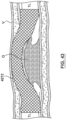
- Stent 4272 provides a scaffold which maintains the subintimal tract in an open condition capable of carrying blood downstream of chronic total occlusion CTO. Thereafter, reentry guidewire 170 and catheter 4274 may be removed from the patient, leaving stent 4272 in an expanded configuration and creating a radially supported, subintimal blood flow channel around chronic total occlusion CTO as seen in FIG. 43 . In some cases, it may be desirable to enlarge the diameter of the subintimal tract before advancing stent catheter 4274 into and through it.
- Such enlargement of the subintimal tract may be accomplished by passing a balloon catheter over reentry guidewire 170 and inflating the balloon to dilate the tract, or may be any other suitable tract enlarging, dilating or de-bulking instrument that may be passed over reentry guidewire 170.
Landscapes
- Health & Medical Sciences (AREA)
- Life Sciences & Earth Sciences (AREA)
- Heart & Thoracic Surgery (AREA)
- Surgery (AREA)
- Animal Behavior & Ethology (AREA)
- General Health & Medical Sciences (AREA)
- Biomedical Technology (AREA)
- Veterinary Medicine (AREA)
- Public Health (AREA)
- Engineering & Computer Science (AREA)
- Molecular Biology (AREA)
- Medical Informatics (AREA)
- Nuclear Medicine, Radiotherapy & Molecular Imaging (AREA)
- Biophysics (AREA)
- Pulmonology (AREA)
- Anesthesiology (AREA)
- Hematology (AREA)
- Pathology (AREA)
- Orthopedic Medicine & Surgery (AREA)
- Vascular Medicine (AREA)
- Child & Adolescent Psychology (AREA)
- Media Introduction/Drainage Providing Device (AREA)
Claims (15)
- Appareil (100) de dérivation d'une occlusion dans un vaisseau sanguin comprenant :un composant de tige externe (102) ayant un orifice latéral (108) proximal à une extrémité distale (106) de celui-ci, le composant de tige externe (102) incluant une lumière d'aiguille (109) le traversant, incluant une partie distale courbée qui se courbe à partir d'un axe longitudinal de l'appareil et se termine à l'orifice latéral (108) du composant de tige externe (102), et une lumière de gonflage (125) le traversant, configurée pour recevoir un fluide de gonflage ;un composant d'aiguille (134) configuré pour être disposé de manière coulissante dans la lumière d ' aiguille (109) du composant de tige externe (102) et amovible de celle-ci ; etun ballonnet gonflable (122) disposé à l'extrémité distale (106) du composant de tige externe (102) et en communication fluidique avec la lumière de gonflage (125) du composant de tige externe (102), le ballonnet (122) incluant une partie de corps (130) disposée distalement par rapport à l'orifice latéral (108) du composant de tige externe (102), la partie de corps (130) du ballonnet (122) ayant un profil aplati dans un état gonflé avec des première et seconde chambres (122A, 122B) s'étendant latéralement depuis les côtés opposés du composant de tige externe (102) pour stabiliser l ' appareil dans un espace sous-intimal.
- Appareil selon la revendication 1, la partie de corps (130) du ballonnet (122) ayant un profil circulaire dans un état dégonflé pour manœuvrer l'appareil à travers une vasculature.
- Appareil selon la revendication 1, au moins une soudure (124) s'étendant sur la partie de corps (130) du ballonnet (122) pour former les première et seconde chambres (122A, 122B) de celui-ci.
- Appareil selon la revendication 3, des première et seconde soudures (124) s'étendant sur des côtés opposés de la partie de corps (130) du ballonnet (122) pour former les première et seconde chambres (122A, 122B) de celui-ci.
- Appareil selon la revendication 1, le ballonnet (122) incluant un col proximal allongé (115) et un col distal (117), la partie de corps (130) du ballonnet (122) s ' étendant entre le col proximal allongé (115) et le col distal (117), et le col proximal allongé (115) du ballonnet (122) étant disposé proximalement et distalement par rapport à l'orifice latéral (108) du composant de tige externe (102).
- Appareil selon la revendication 5, un cône proximal (105) s ' étendant entre le col proximal allongé (115) et la partie de corps (130) du ballonnet (122) et un cône distal (107) s'étendant entre le col distal (117) et la partie de corps (130) du ballonnet (122), chacun des cônes proximal et distal (105, 107) s'étendant selon un angle compris entre 30 et 40 degrés par rapport à l'axe longitudinal de l' appareil.
- Appareil selon la revendication 6, le cône distal (107) s'étendant selon un angle de 30 degrés par rapport à l'axe longitudinal de l'appareil et le cône proximal (105) s'étendant selon un angle de 40 degrés par rapport à l'axe longitudinal de l'appareil.
- Appareil selon la revendication 1, le composant de tige externe (102) incluant également une lumière de fil-guide (129) qui s'étend le long d'au moins une partie du composant de tige externe (102) et se termine au niveau d'un orifice distal à l ' extrémité distale (106) du composant de tige externe (102), la lumière de fil-guide (129) du composant de tige externe (102) étant configurée pour recevoir de manière coulissante un fil-guide à travers celle-ci.
- Appareil selon la revendication 8, un composant tubulaire renforcé (110) étant disposé adjacent à l' extrémité distale (106) du composant de tige externe (102) et le composant tubulaire renforcé (110) définissant une lumière en communication fluidique avec la lumière de fil-guide (129) du composant de tige externe (102), le composant tubulaire renforcé (110) s' étendant distalement au-delà de l'extrémité distale (106) du composant de tige externe (102) à travers le ballonnet (122).
- Appareil selon la revendication 9, le composant tubulaire renforcé (110) incluant un élément enroulé (111) intégré dans un tube polymère (113).
- Appareil selon la revendication 1, un logement d' aiguille (116) étant disposé à l'intérieur du composant de tige externe (102) et le logement d'aiguille (116) incluant une partie distale courbée (120) qui définit la partie distale courbée de la lumière d'aiguille (109) et une partie de transition proximale qui a une flexibilité variable le long de sa longueur qui diminue dans une direction distale.
- Appareil selon la revendication 11, le composant d' aiguille (134) ayant une extrémité distale courbée (136) avec la même courbure que la partie distale courbée de la lumière d ' aiguille (109) du composant de tige externe (102) et une pointe distale (137) du composant d' aiguille (134) étant configurée pour pénétrer une paroi du vaisseau.
- Appareil selon la revendication 12, dans une première configuration de l'appareil, l'extrémité distale courbée (136) du composant d ' aiguille (134) étant maintenue sous une forme redressée à l'intérieur du logement d ' aiguille (116) et dans une seconde configuration de l ' appareil, l ' extrémité distale courbée (136) du composant d'aiguille (134) s'étendant depuis l'orifice latéral (108) du composant de tige externe (102) et se courbant par rapport à l'axe longitudinal de l'appareil.
- Appareil selon la revendication 12, le composant d' aiguille (134) incluant un segment droit (2145) disposé entre l'extrémité distale courbée (136) et la pointe distale (137).
- Appareil selon la revendication 11, une pointe distale du logement d'aiguille (116) incluant une coupe en biseau (128) formant une ouverture configurée pour s' intégrer dans le composant de tige externe (102).
Applications Claiming Priority (2)
| Application Number | Priority Date | Filing Date | Title |
|---|---|---|---|
| US14/877,351 US10327791B2 (en) | 2015-10-07 | 2015-10-07 | Occlusion bypassing apparatus with a re-entry needle and a distal stabilization balloon |
| PCT/US2016/055659 WO2017062559A1 (fr) | 2015-10-07 | 2016-10-06 | Appareil de dérivation d'occlusion muni d'une aiguille de ré-entrée et d'un ballonnet de stabilisation distal |
Publications (2)
| Publication Number | Publication Date |
|---|---|
| EP3359239A1 EP3359239A1 (fr) | 2018-08-15 |
| EP3359239B1 true EP3359239B1 (fr) | 2024-11-27 |
Family
ID=57137318
Family Applications (1)
| Application Number | Title | Priority Date | Filing Date |
|---|---|---|---|
| EP16781978.8A Active EP3359239B1 (fr) | 2015-10-07 | 2016-10-06 | Appareil de dérivation d'occlusion muni d'une aiguille de ré-entrée et d'un ballonnet de stabilisation distal |
Country Status (4)
| Country | Link |
|---|---|
| US (1) | US10327791B2 (fr) |
| EP (1) | EP3359239B1 (fr) |
| CN (1) | CN108136159B (fr) |
| WO (1) | WO2017062559A1 (fr) |
Families Citing this family (168)
| Publication number | Priority date | Publication date | Assignee | Title |
|---|---|---|---|---|
| KR101334502B1 (ko) | 2005-10-19 | 2013-12-05 | 펄사 배스큘러, 아이엔씨. | 내강과 조직 결함을 치료하고 혈관내 결찰을 위한 장치 및 시스템 |
| US9402707B2 (en) | 2008-07-22 | 2016-08-02 | Neuravi Limited | Clot capture systems and associated methods |
| AU2009289488B2 (en) | 2008-09-05 | 2015-09-10 | Pulsar Vascular, Inc. | Systems and methods for supporting or occluding a physiological opening or cavity |
| EP2629684B1 (fr) | 2010-10-22 | 2018-07-25 | Neuravi Limited | Système de mise en prise et de retrait de caillot |
| ES3029850T3 (en) | 2011-03-09 | 2025-06-25 | Neuravi Ltd | A clot retrieval device for removing occlusive clot from a blood vessel |
| US12076037B2 (en) | 2011-03-09 | 2024-09-03 | Neuravi Limited | Systems and methods to restore perfusion to a vessel |
| US11259824B2 (en) | 2011-03-09 | 2022-03-01 | Neuravi Limited | Clot retrieval device for removing occlusive clot from a blood vessel |
| ES2656328T3 (es) | 2011-06-03 | 2018-02-26 | Pulsar Vascular, Inc. | Dispositivos de aneurismo con mecanismos de anclaje adicionales y sistemas asociados |
| EP3738527A1 (fr) | 2011-10-05 | 2020-11-18 | Pulsar Vascular, Inc. | Dispositifs de fermeture d'une ouverture anatomique |
| US10603157B2 (en) | 2013-03-13 | 2020-03-31 | DePuy Synthes Products, Inc. | Braid implant delivery and retraction device with distal engagement |
| US10561509B2 (en) | 2013-03-13 | 2020-02-18 | DePuy Synthes Products, Inc. | Braided stent with expansion ring and method of delivery |
| TR201901830T4 (tr) | 2013-03-14 | 2019-03-21 | Neuravi Ltd | Kan damarlarından akut tıkanıkların giderilmesine yönelik cihazlar ve metotlar. |
| EP3536252B1 (fr) | 2013-03-14 | 2023-09-13 | Neuravi Limited | Dispositif de récupération de caillot pour éliminer un caillot d'occlusion d'un vaisseau sanguin |
| US9433429B2 (en) | 2013-03-14 | 2016-09-06 | Neuravi Limited | Clot retrieval devices |
| US10285720B2 (en) | 2014-03-11 | 2019-05-14 | Neuravi Limited | Clot retrieval system for removing occlusive clot from a blood vessel |
| US11076860B2 (en) | 2014-03-31 | 2021-08-03 | DePuy Synthes Products, Inc. | Aneurysm occlusion device |
| US11154302B2 (en) | 2014-03-31 | 2021-10-26 | DePuy Synthes Products, Inc. | Aneurysm occlusion device |
| ES2989493T3 (es) | 2014-06-13 | 2024-11-26 | Neuravi Ltd | Dispositivos para eliminar las obstrucciones agudas de los vasos sanguíneos |
| US10265086B2 (en) | 2014-06-30 | 2019-04-23 | Neuravi Limited | System for removing a clot from a blood vessel |
| US10391282B2 (en) | 2014-07-08 | 2019-08-27 | Teleflex Innovations S.À.R.L. | Guidewires and methods for percutaneous occlusion crossing |
| US9918718B2 (en) | 2014-08-08 | 2018-03-20 | DePuy Synthes Products, Inc. | Embolic coil delivery system with retractable mechanical release mechanism |
| US10206796B2 (en) | 2014-08-27 | 2019-02-19 | DePuy Synthes Products, Inc. | Multi-strand implant with enhanced radiopacity |
| US9782178B2 (en) | 2014-09-19 | 2017-10-10 | DePuy Synthes Products, Inc. | Vasculature occlusion device detachment system with tapered corewire and heater activated fiber detachment |
| HK1247066A1 (zh) | 2014-11-26 | 2018-09-21 | Neuravi Limited | 从血管除去阻塞性血栓的取血栓装置 |
| US11253278B2 (en) | 2014-11-26 | 2022-02-22 | Neuravi Limited | Clot retrieval system for removing occlusive clot from a blood vessel |
| US10617435B2 (en) | 2014-11-26 | 2020-04-14 | Neuravi Limited | Clot retrieval device for removing clot from a blood vessel |
| US10285710B2 (en) | 2016-06-01 | 2019-05-14 | DePuy Synthes Products, Inc. | Endovascular detachment system with flexible distal end and heater activated detachment |
| EP3782562A1 (fr) | 2016-08-17 | 2021-02-24 | Neuravi Limited | Dispositif de récupération de caillot pour éliminer un caillot d'occlusion dans un vaisseau sanguin |
| US10076428B2 (en) | 2016-08-25 | 2018-09-18 | DePuy Synthes Products, Inc. | Expansion ring for a braided stent |
| CN109906058B (zh) | 2016-09-06 | 2022-06-07 | 尼尔拉维有限公司 | 用于从血管移除闭塞凝块的凝块取回装置 |
| US10292851B2 (en) | 2016-09-30 | 2019-05-21 | DePuy Synthes Products, Inc. | Self-expanding device delivery apparatus with dual function bump |
| US10517708B2 (en) | 2016-10-26 | 2019-12-31 | DePuy Synthes Products, Inc. | Multi-basket clot capturing device |
| US10905853B2 (en) | 2017-01-17 | 2021-02-02 | DePuy Synthes Products, Inc. | System and method for delivering a catheter |
| US10881497B2 (en) | 2017-01-26 | 2021-01-05 | DePuy Synthes Products, Inc. | Composite vascular flow diverter |
| CN110545739A (zh) | 2017-02-23 | 2019-12-06 | 德普伊新特斯产品公司 | 动脉瘤装置及递送系统 |
| US12263035B2 (en) * | 2017-03-30 | 2025-04-01 | Philips Image Guided Therapy Corporation | Directional markers for intraluminal imaging device |
| WO2019083757A1 (fr) | 2017-10-26 | 2019-05-02 | Teleflex Innovations S.A.R.L. | Ensemble et dispositif de cathéter sous-intimal |
| US10806462B2 (en) | 2017-12-21 | 2020-10-20 | DePuy Synthes Products, Inc. | Implantable medical device detachment system with split tube and cylindrical coupling |
| US10751065B2 (en) | 2017-12-22 | 2020-08-25 | DePuy Synthes Products, Inc. | Aneurysm device and delivery system |
| US10905430B2 (en) | 2018-01-24 | 2021-02-02 | DePuy Synthes Products, Inc. | Aneurysm device and delivery system |
| US10912542B2 (en) * | 2018-03-14 | 2021-02-09 | Spiration, Inc. | Catheter assembly with offset device for tissue sampling |
| US20190282218A1 (en) * | 2018-03-14 | 2019-09-19 | SPIRATION, INC., d/b/a OLYMPUS RESPIRATORY AMERICA | Catheter Assembly With Offset Device For Tissue Sampling |
| US10918390B2 (en) | 2018-03-30 | 2021-02-16 | DePuy Synthes Products, Inc. | Helical balloon assist device and method for using the same |
| US10786259B2 (en) | 2018-03-30 | 2020-09-29 | DePuy Synthes Products, Inc. | Split balloon assist device and method for using the same |
| US10806461B2 (en) | 2018-04-27 | 2020-10-20 | DePuy Synthes Products, Inc. | Implantable medical device detachment system with split tube |
| US11058430B2 (en) | 2018-05-25 | 2021-07-13 | DePuy Synthes Products, Inc. | Aneurysm device and delivery system |
| US11596412B2 (en) | 2018-05-25 | 2023-03-07 | DePuy Synthes Products, Inc. | Aneurysm device and delivery system |
| US10939915B2 (en) | 2018-05-31 | 2021-03-09 | DePuy Synthes Products, Inc. | Aneurysm device and delivery system |
| US10667833B2 (en) | 2018-06-08 | 2020-06-02 | Neuravi Limited | Guidewire with an atraumatic clot-circumventing configured distal end for use in an endovascular medical system |
| US10898216B2 (en) | 2018-06-13 | 2021-01-26 | DePuy Synthes Products, Inc. | Vasculature obstruction capture device |
| AU2019204522A1 (en) | 2018-07-30 | 2020-02-13 | DePuy Synthes Products, Inc. | Systems and methods of manufacturing and using an expansion ring |
| US10905431B2 (en) | 2018-08-03 | 2021-02-02 | DePuy Synthes Products, Inc. | Spiral delivery system for embolic braid |
| US10278848B1 (en) | 2018-08-06 | 2019-05-07 | DePuy Synthes Products, Inc. | Stent delivery with expansion assisting delivery wire |
| US10456280B1 (en) | 2018-08-06 | 2019-10-29 | DePuy Synthes Products, Inc. | Systems and methods of using a braided implant |
| US11051825B2 (en) | 2018-08-08 | 2021-07-06 | DePuy Synthes Products, Inc. | Delivery system for embolic braid |
| US10813780B2 (en) | 2018-08-08 | 2020-10-27 | DePuy Synthes Products, Inc. | Intraluminal implant delivery system and method |
| US10842498B2 (en) | 2018-09-13 | 2020-11-24 | Neuravi Limited | Systems and methods of restoring perfusion to a vessel |
| JP2020044335A (ja) | 2018-09-20 | 2020-03-26 | デピュイ・シンセス・プロダクツ・インコーポレイテッド | 成形されたワイヤを有するステント |
| US11123077B2 (en) | 2018-09-25 | 2021-09-21 | DePuy Synthes Products, Inc. | Intrasaccular device positioning and deployment system |
| US11406416B2 (en) | 2018-10-02 | 2022-08-09 | Neuravi Limited | Joint assembly for vasculature obstruction capture device |
| US11253287B2 (en) | 2018-10-04 | 2022-02-22 | Neuravi Limited | Retrograde blood flow occlusion flushing device |
| US11076861B2 (en) | 2018-10-12 | 2021-08-03 | DePuy Synthes Products, Inc. | Folded aneurysm treatment device and delivery method |
| NL2021849B1 (en) * | 2018-10-22 | 2020-05-13 | Mat Nv | System and method for catheter based intervention |
| US11406392B2 (en) | 2018-12-12 | 2022-08-09 | DePuy Synthes Products, Inc. | Aneurysm occluding device for use with coagulating agents |
| US11147562B2 (en) | 2018-12-12 | 2021-10-19 | DePuy Synthes Products, Inc. | Systems and methods for embolic implant detachment |
| US11272939B2 (en) | 2018-12-18 | 2022-03-15 | DePuy Synthes Products, Inc. | Intrasaccular flow diverter for treating cerebral aneurysms |
| US11039944B2 (en) | 2018-12-27 | 2021-06-22 | DePuy Synthes Products, Inc. | Braided stent system with one or more expansion rings |
| FR3092000B1 (fr) * | 2019-01-28 | 2023-02-24 | Hopitaux Paris Assist Publique | Canule d’injection, système d’injection d’un fluide |
| US11134953B2 (en) | 2019-02-06 | 2021-10-05 | DePuy Synthes Products, Inc. | Adhesive cover occluding device for aneurysm treatment |
| US11273285B2 (en) | 2019-02-07 | 2022-03-15 | DePuy Synthes Products, Inc. | Ancillary device for detaching implants |
| EP4000540B1 (fr) | 2019-03-04 | 2024-02-14 | Neuravi Limited | Cathéter de récupération de caillot actionné |
| US11382633B2 (en) | 2019-03-06 | 2022-07-12 | DePuy Synthes Products, Inc. | Strut flow diverter for cerebral aneurysms and methods for preventing strut entanglement |
| US11337706B2 (en) | 2019-03-27 | 2022-05-24 | DePuy Synthes Products, Inc. | Aneurysm treatment device |
| US11185334B2 (en) | 2019-03-28 | 2021-11-30 | DePuy Synthes Products, Inc. | Single lumen reduced profile occlusion balloon catheter |
| CN110124182A (zh) * | 2019-04-04 | 2019-08-16 | 董鹏 | 球囊导管 |
| EP4736931A2 (fr) * | 2019-04-05 | 2026-05-06 | Traverse Vascular, Inc. | Cathéters de rentrée pour traverser des occlusions totales chroniques |
| US11051928B2 (en) | 2019-04-11 | 2021-07-06 | Neuravi Limited | Floating carotid filter |
| US11931522B2 (en) | 2019-05-09 | 2024-03-19 | Neuravi Limited | Inflation lumen kink protection and balloon profile |
| US11571553B2 (en) | 2019-05-09 | 2023-02-07 | Neuravi Limited | Balloon guide catheter with thermally expandable material |
| US11957855B2 (en) | 2019-05-09 | 2024-04-16 | Neuravi Limited | Balloon guide catheter with positive venting of residual air |
| US11607531B2 (en) | 2019-05-09 | 2023-03-21 | Neuravi Limited | Balloon catheter with venting of residual air in a proximal direction |
| USD959659S1 (en) | 2019-05-10 | 2022-08-02 | DePuy Synthes Products, Inc. | Implant release handle |
| US11672542B2 (en) | 2019-05-21 | 2023-06-13 | DePuy Synthes Products, Inc. | Aneurysm treatment with pushable ball segment |
| US11602350B2 (en) | 2019-12-05 | 2023-03-14 | DePuy Synthes Products, Inc. | Intrasaccular inverting braid with highly flexible fill material |
| US11413046B2 (en) | 2019-05-21 | 2022-08-16 | DePuy Synthes Products, Inc. | Layered braided aneurysm treatment device |
| US11607226B2 (en) | 2019-05-21 | 2023-03-21 | DePuy Synthes Products, Inc. | Layered braided aneurysm treatment device with corrugations |
| US11278292B2 (en) | 2019-05-21 | 2022-03-22 | DePuy Synthes Products, Inc. | Inverting braided aneurysm treatment system and method |
| US10653425B1 (en) | 2019-05-21 | 2020-05-19 | DePuy Synthes Products, Inc. | Layered braided aneurysm treatment device |
| US12446886B2 (en) | 2019-05-21 | 2025-10-21 | DePuy Synthes Products, Inc. | Semispherical braided aneurysm treatment system and method |
| US11497504B2 (en) | 2019-05-21 | 2022-11-15 | DePuy Synthes Products, Inc. | Aneurysm treatment with pushable implanted braid |
| US11406403B2 (en) | 2019-06-14 | 2022-08-09 | Neuravi Limited | Visibility of mechanical thrombectomy device during diagnostic imaging |
| US11109939B2 (en) | 2019-06-14 | 2021-09-07 | DePuy Synthes Products, Inc. | Intravascular devices with radiopaque body markers |
| US11253265B2 (en) | 2019-06-18 | 2022-02-22 | DePuy Synthes Products, Inc. | Pull wire detachment for intravascular devices |
| US11426174B2 (en) | 2019-10-03 | 2022-08-30 | DePuy Synthes Products, Inc. | Medical device delivery member with flexible stretch resistant mechanical release |
| US11207494B2 (en) | 2019-07-03 | 2021-12-28 | DePuy Synthes Products, Inc. | Medical device delivery member with flexible stretch resistant distal portion |
| US11266427B2 (en) | 2019-07-10 | 2022-03-08 | Neuravi Limited | Self-expanding intravascular medical device |
| US11266426B2 (en) | 2019-07-10 | 2022-03-08 | DePuy Synthes Products, Inc. | Streamlined treatment of clot removal, angioplasty and prevention of restenosis using a single integrated intravascular device |
| US11395675B2 (en) | 2019-07-11 | 2022-07-26 | DePuy Synthes Products, Inc. | Clot retriever cleaning for reinsertion |
| ES2987037T3 (es) | 2019-09-11 | 2024-11-13 | Neuravi Ltd | Catéter bucal expansible |
| US11439403B2 (en) | 2019-09-17 | 2022-09-13 | DePuy Synthes Products, Inc. | Embolic coil proximal connecting element and stretch resistant fiber |
| US12376859B2 (en) | 2019-09-17 | 2025-08-05 | DePuy Synthes Products, Inc. | Embolic coil proximal connecting element and stretch resistant fiber |
| CN114340522B (zh) * | 2019-09-19 | 2026-04-21 | 爱德华兹生命科学公司 | 经导管穿刺针系统 |
| US11712231B2 (en) | 2019-10-29 | 2023-08-01 | Neuravi Limited | Proximal locking assembly design for dual stent mechanical thrombectomy device |
| US20210128183A1 (en) | 2019-10-31 | 2021-05-06 | Neuravi Limited | Thrombectomy and stenting system |
| US11376013B2 (en) | 2019-11-18 | 2022-07-05 | DePuy Synthes Products, Inc. | Implant delivery system with braid cup formation |
| US11628282B2 (en) | 2019-11-25 | 2023-04-18 | Neuravi Limited | No preparation balloon guide catheter |
| US11779364B2 (en) | 2019-11-27 | 2023-10-10 | Neuravi Limited | Actuated expandable mouth thrombectomy catheter |
| US11839725B2 (en) | 2019-11-27 | 2023-12-12 | Neuravi Limited | Clot retrieval device with outer sheath and inner catheter |
| US12539130B2 (en) | 2019-11-27 | 2026-02-03 | Neuravi Limited | Aspiration catheter, systems, and methods thereof |
| US11517340B2 (en) | 2019-12-03 | 2022-12-06 | Neuravi Limited | Stentriever devices for removing an occlusive clot from a vessel and methods thereof |
| US11457926B2 (en) | 2019-12-18 | 2022-10-04 | DePuy Synthes Products, Inc. | Implant having an intrasaccular section and intravascular section |
| CA3168819A1 (fr) | 2019-12-24 | 2021-07-01 | Encompass Vascular, Inc. | Dispositifs medicaux pour distribution de fluide |
| US11457922B2 (en) | 2020-01-22 | 2022-10-04 | DePuy Synthes Products, Inc. | Medical device delivery member with flexible stretch resistant distal portion |
| US11992241B2 (en) | 2020-01-31 | 2024-05-28 | DePuy Synthes Products, Inc. | System to assist delivery of a mechanical intravascular treatment device |
| US11957354B2 (en) | 2020-02-10 | 2024-04-16 | DePuy Synthes Products, Inc. | Aneurysm implant support device |
| US11432822B2 (en) | 2020-02-14 | 2022-09-06 | DePuy Synthes Products, Inc. | Intravascular implant deployment system |
| US11633198B2 (en) | 2020-03-05 | 2023-04-25 | Neuravi Limited | Catheter proximal joint |
| US11944327B2 (en) | 2020-03-05 | 2024-04-02 | Neuravi Limited | Expandable mouth aspirating clot retrieval catheter |
| US11883043B2 (en) | 2020-03-31 | 2024-01-30 | DePuy Synthes Products, Inc. | Catheter funnel extension |
| US11759217B2 (en) | 2020-04-07 | 2023-09-19 | Neuravi Limited | Catheter tubular support |
| US11871946B2 (en) | 2020-04-17 | 2024-01-16 | Neuravi Limited | Clot retrieval device for removing clot from a blood vessel |
| US11717308B2 (en) | 2020-04-17 | 2023-08-08 | Neuravi Limited | Clot retrieval device for removing heterogeneous clots from a blood vessel |
| US11730501B2 (en) | 2020-04-17 | 2023-08-22 | Neuravi Limited | Floating clot retrieval device for removing clots from a blood vessel |
| US11523831B2 (en) | 2020-04-30 | 2022-12-13 | DePuy Synthes Products, Inc. | Intrasaccular flow diverter |
| US11737771B2 (en) | 2020-06-18 | 2023-08-29 | Neuravi Limited | Dual channel thrombectomy device |
| US11937836B2 (en) | 2020-06-22 | 2024-03-26 | Neuravi Limited | Clot retrieval system with expandable clot engaging framework |
| US11395669B2 (en) | 2020-06-23 | 2022-07-26 | Neuravi Limited | Clot retrieval device with flexible collapsible frame |
| US11439418B2 (en) | 2020-06-23 | 2022-09-13 | Neuravi Limited | Clot retrieval device for removing clot from a blood vessel |
| US11951026B2 (en) | 2020-06-30 | 2024-04-09 | DePuy Synthes Products, Inc. | Implantable medical device detachment system with flexible braid section |
| US12447319B2 (en) | 2020-07-29 | 2025-10-21 | Neuravi Limited | Enhanced balloon bonding for balloon guide catheters while minimizing outer profiles |
| US20220031341A1 (en) | 2020-07-29 | 2022-02-03 | Neuravi Limited | Adhesive-Free Bonded Balloon for a Balloon Guide Catheter With Minimal Outer Profile |
| US11864781B2 (en) | 2020-09-23 | 2024-01-09 | Neuravi Limited | Rotating frame thrombectomy device |
| US12440646B2 (en) | 2020-11-06 | 2025-10-14 | DePuy Synthes Products, Inc. | Catheter braid wire with variable cross-section shape |
| US11786698B2 (en) | 2020-12-08 | 2023-10-17 | DePuy Synthes Products, Inc. | Catheter with textured surface |
| US11826520B2 (en) | 2020-12-08 | 2023-11-28 | DePuy Synthes Products, Inc. | Catheter designs for enhanced column strength |
| US11937837B2 (en) | 2020-12-29 | 2024-03-26 | Neuravi Limited | Fibrin rich / soft clot mechanical thrombectomy device |
| US12029442B2 (en) | 2021-01-14 | 2024-07-09 | Neuravi Limited | Systems and methods for a dual elongated member clot retrieval apparatus |
| WO2022182598A1 (fr) | 2021-02-23 | 2022-09-01 | Encompass Vascular, Inc. | Dispositifs médicaux pour la distribution de fluide et procédés d'utilisation et de fabrication |
| US11872354B2 (en) | 2021-02-24 | 2024-01-16 | Neuravi Limited | Flexible catheter shaft frame with seam |
| US12064130B2 (en) | 2021-03-18 | 2024-08-20 | Neuravi Limited | Vascular obstruction retrieval device having sliding cages pinch mechanism |
| WO2022232589A1 (fr) | 2021-04-30 | 2022-11-03 | Encompass Vascular, Inc. | Dispositifs médicaux pour la distribution de fluide et procédés d'utilisation et de fabrication |
| US11974764B2 (en) | 2021-06-04 | 2024-05-07 | Neuravi Limited | Self-orienting rotating stentriever pinching cells |
| US11998213B2 (en) | 2021-07-14 | 2024-06-04 | DePuy Synthes Products, Inc. | Implant delivery with modified detachment feature and pull wire engagement |
| US12369920B2 (en) | 2021-09-22 | 2025-07-29 | DePuy Synthes Products, Inc. | Introducer sheath having an intentional friction zone to hold in position a delivery system suitable for implantable intravascular devices |
| US11937839B2 (en) | 2021-09-28 | 2024-03-26 | Neuravi Limited | Catheter with electrically actuated expandable mouth |
| US12011186B2 (en) | 2021-10-28 | 2024-06-18 | Neuravi Limited | Bevel tip expandable mouth catheter with reinforcing ring |
| US11751881B2 (en) | 2021-11-26 | 2023-09-12 | DePuy Synthes Products, Inc. | Securement wire withstanding forces during deployment of implantable intravascular treatment device using a delivery and detachment system |
| US12364485B2 (en) | 2021-12-03 | 2025-07-22 | Boston Scientific Scimed, Inc. | Arterial occlusion implant and delivery catheter and methods |
| US11844490B2 (en) | 2021-12-30 | 2023-12-19 | DePuy Synthes Products, Inc. | Suture linkage for inhibiting premature embolic implant deployment |
| US11937824B2 (en) | 2021-12-30 | 2024-03-26 | DePuy Synthes Products, Inc. | Implant detachment systems with a modified pull wire |
| US12508032B2 (en) | 2021-12-31 | 2025-12-30 | DePuy Synthes Products, Inc. | Medical device delivery systems with twisting loop wires |
| US12011171B2 (en) | 2022-01-06 | 2024-06-18 | DePuy Synthes Products, Inc. | Systems and methods for inhibiting premature embolic implant deployment |
| US12220131B2 (en) | 2022-01-06 | 2025-02-11 | DePuy Synthes Products, Inc. | Delivery and detachment system imposing a friction force on a securement wire to minimize movement of an implantable intravascular device |
| US11937825B2 (en) | 2022-03-02 | 2024-03-26 | DePuy Synthes Products, Inc. | Hook wire for preventing premature embolic implant detachment |
| US12471924B2 (en) | 2022-03-02 | 2025-11-18 | DePuy Synthes Products, Inc. | Flexible feature for embolic implant deployment |
| US12137915B2 (en) | 2022-03-03 | 2024-11-12 | DePuy Synthes Products, Inc. | Elongating wires for inhibiting premature implant detachment |
| IT202200004412A1 (it) | 2022-03-08 | 2023-09-08 | Mauro Carlino | Catetere a palloncino multilume e procedura chirurgica endovascolare impiegante lo stesso. |
| US11937826B2 (en) | 2022-03-14 | 2024-03-26 | DePuy Synthes Products, Inc. | Proximal link wire for preventing premature implant detachment |
| US12402886B2 (en) | 2022-06-23 | 2025-09-02 | DePuy Synthes Products, Inc. | Detachment indicator for implant deployment |
| CN117462137A (zh) * | 2022-07-20 | 2024-01-30 | 上海微创电生理医疗科技股份有限公司 | 医疗导管 |
| US12458380B2 (en) | 2022-07-29 | 2025-11-04 | Neuravi Limited | Mechanical thrombectomy device for capture and removal of occlusions |
| US12446888B2 (en) | 2022-08-26 | 2025-10-21 | Depuy Synthes Products, Inc | Twister implant detachment mechanism |
| US12396730B2 (en) | 2022-09-28 | 2025-08-26 | DePuy Synthes Products, Inc. | Braided implant with detachment mechanism |
| CN121079048B (zh) | 2023-03-03 | 2026-04-10 | 塞纳医疗公司 | 用于分流导管的可扩展元件 |
| WO2024211764A1 (fr) | 2023-04-06 | 2024-10-10 | Theraheart Inc. | Éléments de découpage pour cathéters de dérivation |
| US12262943B2 (en) | 2023-06-15 | 2025-04-01 | Theraheart Inc. | Expandable ablation mechanisms for shunting catheters |
| US20250058080A1 (en) | 2023-08-17 | 2025-02-20 | Thomas Mowrey | Vascular Access Devices Having Curves |
| US12201354B1 (en) | 2024-04-01 | 2025-01-21 | Theraheart Inc. | Expandable ablation mechanisms for shunting catheters |
Family Cites Families (126)
| Publication number | Priority date | Publication date | Assignee | Title |
|---|---|---|---|---|
| US3568659A (en) | 1968-09-24 | 1971-03-09 | James N Karnegis | Disposable percutaneous intracardiac pump and method of pumping blood |
| US4774949A (en) | 1983-06-14 | 1988-10-04 | Fogarty Thomas J | Deflector guiding catheter |
| US4552554A (en) | 1984-06-25 | 1985-11-12 | Medi-Tech Incorporated | Introducing catheter |
| US5002532A (en) | 1987-01-06 | 1991-03-26 | Advanced Cardiovascular Systems, Inc. | Tandem balloon dilatation catheter |
| US5250069A (en) | 1987-02-27 | 1993-10-05 | Terumo Kabushiki Kaisha | Catheter equipped with expansible member and production method thereof |
| US5047045A (en) * | 1989-04-13 | 1991-09-10 | Scimed Life Systems, Inc. | Multi-section coaxial angioplasty catheter |
| US5217434A (en) * | 1991-10-15 | 1993-06-08 | Scimed Life Systems, Inc. | Innerless dilatation catheter with balloon stretch valve |
| US5304134A (en) * | 1992-01-17 | 1994-04-19 | Danforth Biomedical, Inc. | Lubricious yet bondable catheter channel sleeve for over-the-wire catheters |
| US5569184A (en) | 1992-04-29 | 1996-10-29 | Cardiovascular Dynamics, Inc. | Delivery and balloon dilatation catheter and method of using |
| US5460608A (en) | 1994-01-25 | 1995-10-24 | Scimed Life Systems, Inc. | Kink free catheter |
| US5501667A (en) * | 1994-03-15 | 1996-03-26 | Cordis Corporation | Perfusion balloon and method of use and manufacture |
| WO1996009848A1 (fr) * | 1994-09-26 | 1996-04-04 | Medtronic, Inc. | Pointe distale souple de catheter |
| US5667493A (en) | 1994-12-30 | 1997-09-16 | Janacek; Jaroslav | Dilation catheter |
| US5599324A (en) | 1995-05-04 | 1997-02-04 | Boston Scientific Corporation | Catheter for administering a liquid agent |
| US5964740A (en) | 1996-07-09 | 1999-10-12 | Asahi Kogaku Kogyo Kabushiki Kaisha | Treatment accessory for an endoscope |
| CA2223219A1 (fr) | 1995-06-07 | 1999-05-19 | Frank Louw | Catheter d'occlusion de branches laterales muni d'un endoscope integre pour effectuer une occlusion visualisee par endoscopie des branches laterales d'une cavite naturelle |
| US5707389A (en) | 1995-06-07 | 1998-01-13 | Baxter International Inc. | Side branch occlusion catheter device having integrated endoscope for performing endoscopically visualized occlusion of the side branches of an anatomical passageway |
| US6726677B1 (en) | 1995-10-13 | 2004-04-27 | Transvascular, Inc. | Stabilized tissue penetrating catheters |
| US6375615B1 (en) | 1995-10-13 | 2002-04-23 | Transvascular, Inc. | Tissue penetrating catheters having integral imaging transducers and their methods of use |
| US6302875B1 (en) | 1996-10-11 | 2001-10-16 | Transvascular, Inc. | Catheters and related devices for forming passageways between blood vessels or other anatomical structures |
| US6283983B1 (en) | 1995-10-13 | 2001-09-04 | Transvascular, Inc. | Percutaneous in-situ coronary bypass method and apparatus |
| IL151563A0 (en) | 1995-10-13 | 2003-04-10 | Transvascular Inc | A longitudinal compression apparatus for compressing tissue |
| ATE515237T1 (de) | 1995-10-13 | 2011-07-15 | Medtronic Vascular Inc | Vorrichtung und system bei einem interstitiellen transvaskulären eingriff |
| AUPN775296A0 (en) | 1996-01-25 | 1996-02-22 | Endogad Research Pty Limited | Directional catheter |
| US6709444B1 (en) | 1996-02-02 | 2004-03-23 | Transvascular, Inc. | Methods for bypassing total or near-total obstructions in arteries or other anatomical conduits |
| US6579311B1 (en) | 1996-02-02 | 2003-06-17 | Transvascular, Inc. | Method for interstitial transvascular intervention |
| US5800389A (en) | 1996-02-09 | 1998-09-01 | Emx, Inc. | Biopsy device |
| US6203524B1 (en) | 1997-02-10 | 2001-03-20 | Emx, Inc. | Surgical and pharmaceutical site access guide and methods |
| US5830224A (en) | 1996-03-15 | 1998-11-03 | Beth Israel Deaconess Medical Center | Catheter apparatus and methodology for generating a fistula on-demand between closely associated blood vessels at a pre-chosen anatomic site in-vivo |
| US5916194A (en) | 1996-05-24 | 1999-06-29 | Sarcos, Inc. | Catheter/guide wire steering apparatus and method |
| US6379319B1 (en) | 1996-10-11 | 2002-04-30 | Transvascular, Inc. | Systems and methods for directing and snaring guidewires |
| US6432127B1 (en) | 1996-10-11 | 2002-08-13 | Transvascular, Inc. | Devices for forming and/or maintaining connections between adjacent anatomical conduits |
| US6261260B1 (en) | 1997-04-15 | 2001-07-17 | Terumo Kabushiki Kaisha | Balloon for medical tube and medical tube equipped with the same |
| US6071292A (en) | 1997-06-28 | 2000-06-06 | Transvascular, Inc. | Transluminal methods and devices for closing, forming attachments to, and/or forming anastomotic junctions in, luminal anatomical structures |
| US6217527B1 (en) | 1998-09-30 | 2001-04-17 | Lumend, Inc. | Methods and apparatus for crossing vascular occlusions |
| US20050171478A1 (en) | 1998-01-13 | 2005-08-04 | Selmon Matthew R. | Catheter system for crossing total occlusions in vasculature |
| US6231546B1 (en) | 1998-01-13 | 2001-05-15 | Lumend, Inc. | Methods and apparatus for crossing total occlusions in blood vessels |
| US6241667B1 (en) | 1998-01-15 | 2001-06-05 | Lumend, Inc. | Catheter apparatus for guided transvascular treatment of arterial occlusions |
| US20060074442A1 (en) | 2000-04-06 | 2006-04-06 | Revascular Therapeutics, Inc. | Guidewire for crossing occlusions or stenoses |
| US20080140101A1 (en) | 2006-12-07 | 2008-06-12 | Revascular Therapeutic, Inc. | Apparatus for crossing occlusions or stenoses |
| EP1067874B1 (fr) | 1998-03-31 | 2008-04-23 | Medtronic Vascular, Inc. | Catheters et systemes de creation de passages pour derivation arterio-veineuse in-situ percutanee |
| US6196230B1 (en) | 1998-09-10 | 2001-03-06 | Percardia, Inc. | Stent delivery system and method of use |
| US6514228B1 (en) | 1999-03-05 | 2003-02-04 | Scimed Life Systems, Inc. | Balloon catheter having high flow tip |
| US6355027B1 (en) | 1999-06-09 | 2002-03-12 | Possis Medical, Inc. | Flexible microcatheter |
| US6508824B1 (en) | 2000-02-18 | 2003-01-21 | Transvascular, Inc. | Catheter-based methods for enlarging blood vessels to facilitate the formation of penetration tracts, fistulas and/or blood flow channels |
| US6458098B1 (en) | 2000-03-17 | 2002-10-01 | Nozomu Kanesaka | Vascular therapy device |
| US6511474B1 (en) | 2000-07-12 | 2003-01-28 | Corpak, Inc. | Bolus for non-occluding high flow enteral feeding tube |
| US7004173B2 (en) | 2000-12-05 | 2006-02-28 | Lumend, Inc. | Catheter system for vascular re-entry from a sub-intimal space |
| US20020072706A1 (en) | 2000-12-11 | 2002-06-13 | Thomas Hiblar | Transluminal drug delivery catheter |
| US20040167554A1 (en) | 2000-12-20 | 2004-08-26 | Fox Hollow Technologies, Inc. | Methods and devices for reentering a true lumen from a subintimal space |
| US7357794B2 (en) | 2002-01-17 | 2008-04-15 | Medtronic Vascular, Inc. | Devices, systems and methods for acute or chronic delivery of substances or apparatus to extravascular treatment sites |
| US6602241B2 (en) | 2001-01-17 | 2003-08-05 | Transvascular, Inc. | Methods and apparatus for acute or chronic delivery of substances or apparatus to extravascular treatment sites |
| US6663577B2 (en) | 2001-12-07 | 2003-12-16 | Abbott Laboratories | Catheter deployment device |
| JP2003320031A (ja) | 2002-02-26 | 2003-11-11 | Buaayu:Kk | バルーンカテーテル |
| US7141041B2 (en) | 2003-03-19 | 2006-11-28 | Mercator Medsystems, Inc. | Catheters having laterally deployable needles |
| US7534223B2 (en) | 2002-10-08 | 2009-05-19 | Boston Scientific Scimed, Inc. | Catheter with formed guide wire ramp |
| US6835189B2 (en) * | 2002-10-15 | 2004-12-28 | Scimed Life Systems, Inc. | Controlled deployment balloon |
| DE602004011910T2 (de) * | 2003-03-13 | 2009-02-19 | Medtronic Vascular, Inc., Santa Rosa | Optisch geführte penetrationskatheter und ihre anwendungsverfahren |
| US7273485B2 (en) * | 2003-03-20 | 2007-09-25 | Advanced Cardiovascular Systems, Inc. | Balloon catheter having a shaft with a variable stiffness inner tubular member |
| US20050021003A1 (en) | 2003-04-14 | 2005-01-27 | Richard Caso | Apparatus for directional guidance of a vascular device and method of use |
| US8246640B2 (en) | 2003-04-22 | 2012-08-21 | Tyco Healthcare Group Lp | Methods and devices for cutting tissue at a vascular location |
| US7854727B2 (en) | 2003-05-23 | 2010-12-21 | Belsley Scott J | Adjustable device delivery system |
| US7591813B2 (en) * | 2003-10-01 | 2009-09-22 | Micrus Endovascular Corporation | Long nose manipulatable catheter |
| US7320695B2 (en) | 2003-12-31 | 2008-01-22 | Biosense Webster, Inc. | Safe septal needle and method for its use |
| US20050159728A1 (en) | 2004-01-15 | 2005-07-21 | Thomas Medical Products, Inc. | Steerable sheath |
| US7122034B2 (en) | 2004-05-27 | 2006-10-17 | St. Jude Medical, Atrial Fibrillation Division, Inc. | Curved ablation catheter |
| US8241315B2 (en) | 2004-06-24 | 2012-08-14 | Boston Scientific Scimed, Inc. | Apparatus and method for treating occluded vasculature |
| ITTO20040499A1 (it) * | 2004-07-15 | 2004-10-15 | Bitelli Spa | Macchina operatrice in particolare scarificatrice stradale |
| US20060036233A1 (en) | 2004-08-12 | 2006-02-16 | Scimed Life Systems, Inc. | Catheter incorporating a guidewire exit ramp |
| CN101495171A (zh) | 2005-03-30 | 2009-07-29 | 卢门德公司 | 用于穿过脉管系统中的完全闭塞的导管系统 |
| ATE452676T1 (de) | 2005-04-07 | 2010-01-15 | Creganna Technologies Ltd | Lenkbare katheteranordnung |
| US7938819B2 (en) | 2005-09-12 | 2011-05-10 | Bridgepoint Medical, Inc. | Endovascular devices and methods |
| US8083727B2 (en) | 2005-09-12 | 2011-12-27 | Bridgepoint Medical, Inc. | Endovascular devices and methods for exploiting intramural space |
| EP3650074B1 (fr) | 2005-09-12 | 2023-10-25 | Boston Scientific Scimed, Inc. | Dispositifs endovasculaires |
| US20070123925A1 (en) | 2005-11-28 | 2007-05-31 | Medtronic Vascular, Inc. | Pre-curved guiding catheter with mechanically actuated anchor |
| WO2007088961A1 (fr) * | 2006-02-03 | 2007-08-09 | Takata Corporation | Coussin de sécurité gonflable et système de coussin de sécurité gonflable |
| GB0613982D0 (en) | 2006-07-13 | 2006-08-23 | Shturman Leonid | Rotational atherectomy device with fluid inflatable support elements and two torque transmitting coils |
| US8636715B2 (en) | 2006-09-25 | 2014-01-28 | Medtronic Vascular, Inc. | High torque, low profile catheters and methods for transluminal interventions |
| US7762985B2 (en) * | 2006-11-01 | 2010-07-27 | Cook Incorporated | Balloon catheter for treating hardened lesions |
| US11109883B2 (en) | 2006-11-21 | 2021-09-07 | Bridgepoint Medical, Inc. | Endovascular devices and methods for exploiting intramural space |
| US9060802B2 (en) | 2006-11-21 | 2015-06-23 | Bridgepoint Medical, Inc. | Endovascular devices and methods for exploiting intramural space |
| US7879004B2 (en) | 2006-12-13 | 2011-02-01 | University Of Washington | Catheter tip displacement mechanism |
| US8257383B2 (en) | 2007-03-29 | 2012-09-04 | Boston Scientific Limited | Lumen reentry devices and methods |
| US7896840B2 (en) | 2007-04-05 | 2011-03-01 | Boston Scientific Scimed, Inc. | Catheter having internal mechanisms to encourage balloon re-folding |
| JP2009021809A (ja) * | 2007-07-11 | 2009-01-29 | Canon Inc | 撮像装置の駆動方法、撮像装置、及び撮像システム |
| EP2211968B1 (fr) | 2007-10-22 | 2020-02-26 | Bridgepoint Medical, Inc. | Dispositifs pour traverser des occlusions totales chroniques |
| US8403885B2 (en) * | 2007-12-17 | 2013-03-26 | Abbott Cardiovascular Systems Inc. | Catheter having transitioning shaft segments |
| US8758421B2 (en) | 2008-01-30 | 2014-06-24 | Boston Scientific Scimed, Inc. | Medical systems and related methods |
| JP5631744B2 (ja) | 2008-02-05 | 2014-11-26 | ブリッジポイント、メディカル、インコーポレイテッドBridgepoint Medical, Inc. | 血管内の閉塞部分の横断 |
| US8337425B2 (en) | 2008-02-05 | 2012-12-25 | Bridgepoint Medical, Inc. | Endovascular device with a tissue piercing distal probe and associated methods |
| EP4011305B1 (fr) | 2008-04-28 | 2024-12-25 | Boston Scientific Scimed, Inc. | Appareil pour traverser des occlusions dans des vaisseaux sanguins |
| ITMI20081002A1 (it) | 2008-05-30 | 2009-11-30 | Kardia S R L | Dispositivo per il trattamento di occlusioni arteriose degli arti inferiori |
| US8486022B2 (en) | 2008-07-03 | 2013-07-16 | Abbott Cardiovascular Systems Inc. | Needle catheter with an angled distal tip lumen |
| CN201263727Y (zh) * | 2008-09-17 | 2009-07-01 | 易生科技(北京)有限公司 | 一种用于治疗冠状动脉慢性完全闭塞病变的单管腔球囊导管 |
| CN201410210Y (zh) * | 2009-03-27 | 2010-02-24 | 王光辉 | 脑硬膜下血肿插管引导器 |
| US8226566B2 (en) | 2009-06-12 | 2012-07-24 | Flowcardia, Inc. | Device and method for vascular re-entry |
| US8241311B2 (en) | 2009-12-15 | 2012-08-14 | Medtronic Vascular, Inc. | Methods and systems for bypassing an occlusion in a blood vessel |
| JP2011147758A (ja) * | 2010-01-22 | 2011-08-04 | Olympus Corp | 処置具 |
| EP4183441A1 (fr) | 2010-02-26 | 2023-05-24 | The Board of Trustees of the Leland Stanford Junior University | Systèmes de création de valvule endoluminale |
| WO2011162100A1 (fr) | 2010-06-23 | 2011-12-29 | テルモ株式会社 | Dispositif médical |
| WO2014039096A1 (fr) | 2012-09-06 | 2014-03-13 | Avinger, Inc. | Stylet de réintroduction destiné à un cathéter |
| US20120053485A1 (en) | 2010-09-01 | 2012-03-01 | Salient Surgical Technologies, Inc. | Catheter Having Needle And Expandable Support Member And Methods Of Use |
| US8932315B2 (en) | 2010-10-18 | 2015-01-13 | W. L. Gore & Associates, Inc. | Systems and methods for percutaneous occlusion crossing |
| EP2574269B1 (fr) * | 2010-11-25 | 2016-08-31 | Olympus Corporation | Cathéter équipé d'un ballonnet ayant une section d'introduction à rigidité variable |
| US20120197194A1 (en) * | 2011-01-04 | 2012-08-02 | Oscor Inc. | Folding balloon catheter |
| US20140018732A1 (en) | 2011-01-10 | 2014-01-16 | Spotlight Technology Partners Llc | Apparatus and Methods for Accessing and Treating a Body Cavity, Lumen, or Ostium |
| US8852165B2 (en) | 2011-06-16 | 2014-10-07 | II Edward G. Mackay | Endoluminal drug delivery devices and methods |
| US8920449B2 (en) | 2011-06-29 | 2014-12-30 | Cordis Corporation | System and method for re-entering a vessel lumen |
| US8956376B2 (en) | 2011-06-30 | 2015-02-17 | The Spectranetics Corporation | Reentry catheter and method thereof |
| US9814862B2 (en) | 2011-06-30 | 2017-11-14 | The Spectranetics Corporation | Reentry catheter and method thereof |
| US8998936B2 (en) | 2011-06-30 | 2015-04-07 | The Spectranetics Corporation | Reentry catheter and method thereof |
| JP6030655B2 (ja) | 2011-09-19 | 2016-11-24 | ボストン サイエンティフィック サイムド,インコーポレイテッドBoston Scientific Scimed,Inc. | カテーテルおよびカテーテル組立体 |
| AU2012347644B2 (en) * | 2011-12-09 | 2017-04-20 | Boston Scientific Scimed, Inc. | Subintimal recanalization with bio-absorbable stent |
| WO2013164825A2 (fr) | 2012-05-03 | 2013-11-07 | Safeback Re-Entry Medical Ltd | Dispositifs et procédés permettant de contourner des occlusions dans des vaisseaux |
| US20130304108A1 (en) | 2012-05-08 | 2013-11-14 | Daniel C. Weber | Systems and apparatus for treating blood vessels and related methods |
| US9486239B2 (en) | 2012-05-24 | 2016-11-08 | Boston Scientific Scimed, Inc. | Subintimal re-entry device |
| WO2014012008A1 (fr) | 2012-07-13 | 2014-01-16 | Boston Scientific Scimed, Inc. | Système de réentrée sous-intimal |
| US20140142607A1 (en) | 2012-11-21 | 2014-05-22 | Cook Medical Technologies Llc | Lumen Re-Entry System And Method |
| US9398921B2 (en) | 2013-01-30 | 2016-07-26 | Invatec S.P.A. | Catheter with deflectable tip |
| US9095374B2 (en) | 2013-01-30 | 2015-08-04 | Invatec S.P.A. | Catheter with deflectable tip |
| EP2967601B1 (fr) | 2013-03-14 | 2017-11-29 | Boston Scientific Scimed, Inc. | Systèmes et appareil de traitement de vaisseaux sanguins |
| US9301777B2 (en) | 2013-07-29 | 2016-04-05 | Invatec S.P.A. | Occlusion bypassing apparatuses and methods for bypassing an occlusion in a blood vessel |
| US9308356B2 (en) | 2013-07-29 | 2016-04-12 | Invatec S.P.A. | Occlusion bypassing apparatuses and methods for bypassing an occlusion in a blood vessel |
| US20150112304A1 (en) | 2013-10-21 | 2015-04-23 | Invatec S.P.A | Apparatus having a selectively curved distal end and methods for use |
| US20150174371A1 (en) | 2013-12-23 | 2015-06-25 | Cook Medical Technologies Llc | System for bypassing vascular occlusion having puncturing mechanism and method |
| US9446222B2 (en) | 2014-03-05 | 2016-09-20 | Invatec S.P.A. | Catheter assemblies and methods for stabilizing a catheter assembly within a subintimal space |
-
2015
- 2015-10-07 US US14/877,351 patent/US10327791B2/en active Active
-
2016
- 2016-10-06 CN CN201680058738.0A patent/CN108136159B/zh active Active
- 2016-10-06 WO PCT/US2016/055659 patent/WO2017062559A1/fr not_active Ceased
- 2016-10-06 EP EP16781978.8A patent/EP3359239B1/fr active Active
Also Published As
| Publication number | Publication date |
|---|---|
| US20170100141A1 (en) | 2017-04-13 |
| CN108136159B (zh) | 2020-11-27 |
| US10327791B2 (en) | 2019-06-25 |
| EP3359239A1 (fr) | 2018-08-15 |
| WO2017062559A1 (fr) | 2017-04-13 |
| CN108136159A (zh) | 2018-06-08 |
Similar Documents
| Publication | Publication Date | Title |
|---|---|---|
| EP3359239B1 (fr) | Appareil de dérivation d'occlusion muni d'une aiguille de ré-entrée et d'un ballonnet de stabilisation distal | |
| EP3352833B1 (fr) | Appareil de dérivation d'occlusion avec aiguille de réentrée et tube de stabilisation | |
| EP3179928B1 (fr) | Appareil de contournement d'occlusion de flexibilité variable | |
| US11602362B2 (en) | Reentry catheters and methods for traversing chronic total occlusions | |
| US10143824B2 (en) | Catheter assemblies and methods for stabilizing a catheter assembly within a subintimal space | |
| US9308356B2 (en) | Occlusion bypassing apparatuses and methods for bypassing an occlusion in a blood vessel | |
| EP3027257B1 (fr) | Appareils de contournement d'occlusion pour contourner une occlusion dans un vaisseau sanguin | |
| EP2872209B1 (fr) | Système de réintroduction sous-intimale | |
| US20150112304A1 (en) | Apparatus having a selectively curved distal end and methods for use | |
| HK40113608A (en) | Reentry catheters for traversing chronic total occlusions |
Legal Events
| Date | Code | Title | Description |
|---|---|---|---|
| STAA | Information on the status of an ep patent application or granted ep patent |
Free format text: STATUS: THE INTERNATIONAL PUBLICATION HAS BEEN MADE |
|
| PUAI | Public reference made under article 153(3) epc to a published international application that has entered the european phase |
Free format text: ORIGINAL CODE: 0009012 |
|
| STAA | Information on the status of an ep patent application or granted ep patent |
Free format text: STATUS: REQUEST FOR EXAMINATION WAS MADE |
|
| 17P | Request for examination filed |
Effective date: 20180416 |
|
| AK | Designated contracting states |
Kind code of ref document: A1 Designated state(s): AL AT BE BG CH CY CZ DE DK EE ES FI FR GB GR HR HU IE IS IT LI LT LU LV MC MK MT NL NO PL PT RO RS SE SI SK SM TR |
|
| AX | Request for extension of the european patent |
Extension state: BA ME |
|
| DAV | Request for validation of the european patent (deleted) | ||
| DAX | Request for extension of the european patent (deleted) | ||
| STAA | Information on the status of an ep patent application or granted ep patent |
Free format text: STATUS: EXAMINATION IS IN PROGRESS |
|
| 17Q | First examination report despatched |
Effective date: 20221114 |
|
| GRAP | Despatch of communication of intention to grant a patent |
Free format text: ORIGINAL CODE: EPIDOSNIGR1 |
|
| STAA | Information on the status of an ep patent application or granted ep patent |
Free format text: STATUS: GRANT OF PATENT IS INTENDED |
|
| RIC1 | Information provided on ipc code assigned before grant |
Ipc: A61B 17/00 20060101ALN20240516BHEP Ipc: A61M 25/00 20060101ALN20240516BHEP Ipc: A61M 25/02 20060101ALN20240516BHEP Ipc: A61B 17/22 20060101ALN20240516BHEP Ipc: A61B 17/34 20060101ALI20240516BHEP Ipc: A61M 25/10 20130101ALI20240516BHEP Ipc: A61M 25/01 20060101AFI20240516BHEP |
|
| INTG | Intention to grant announced |
Effective date: 20240605 |
|
| GRAS | Grant fee paid |
Free format text: ORIGINAL CODE: EPIDOSNIGR3 |
|
| GRAA | (expected) grant |
Free format text: ORIGINAL CODE: 0009210 |
|
| STAA | Information on the status of an ep patent application or granted ep patent |
Free format text: STATUS: THE PATENT HAS BEEN GRANTED |
|
| AK | Designated contracting states |
Kind code of ref document: B1 Designated state(s): AL AT BE BG CH CY CZ DE DK EE ES FI FR GB GR HR HU IE IS IT LI LT LU LV MC MK MT NL NO PL PT RO RS SE SI SK SM TR |
|
| REG | Reference to a national code |
Ref country code: GB Ref legal event code: FG4D |
|
| REG | Reference to a national code |
Ref country code: CH Ref legal event code: EP |
|
| REG | Reference to a national code |
Ref country code: IE Ref legal event code: FG4D |
|
| REG | Reference to a national code |
Ref country code: DE Ref legal event code: R096 Ref document number: 602016090406 Country of ref document: DE |
|
| REG | Reference to a national code |
Ref country code: LT Ref legal event code: MG9D |
|
| REG | Reference to a national code |
Ref country code: NL Ref legal event code: MP Effective date: 20241127 |
|
| PG25 | Lapsed in a contracting state [announced via postgrant information from national office to epo] |
Ref country code: HR Free format text: LAPSE BECAUSE OF FAILURE TO SUBMIT A TRANSLATION OF THE DESCRIPTION OR TO PAY THE FEE WITHIN THE PRESCRIBED TIME-LIMIT Effective date: 20241127 Ref country code: PT Free format text: LAPSE BECAUSE OF FAILURE TO SUBMIT A TRANSLATION OF THE DESCRIPTION OR TO PAY THE FEE WITHIN THE PRESCRIBED TIME-LIMIT Effective date: 20250327 Ref country code: IS Free format text: LAPSE BECAUSE OF FAILURE TO SUBMIT A TRANSLATION OF THE DESCRIPTION OR TO PAY THE FEE WITHIN THE PRESCRIBED TIME-LIMIT Effective date: 20250327 |
|
| PG25 | Lapsed in a contracting state [announced via postgrant information from national office to epo] |
Ref country code: NL Free format text: LAPSE BECAUSE OF FAILURE TO SUBMIT A TRANSLATION OF THE DESCRIPTION OR TO PAY THE FEE WITHIN THE PRESCRIBED TIME-LIMIT Effective date: 20241127 Ref country code: FI Free format text: LAPSE BECAUSE OF FAILURE TO SUBMIT A TRANSLATION OF THE DESCRIPTION OR TO PAY THE FEE WITHIN THE PRESCRIBED TIME-LIMIT Effective date: 20241127 |
|
| REG | Reference to a national code |
Ref country code: AT Ref legal event code: MK05 Ref document number: 1745142 Country of ref document: AT Kind code of ref document: T Effective date: 20241127 |
|
| PG25 | Lapsed in a contracting state [announced via postgrant information from national office to epo] |
Ref country code: BG Free format text: LAPSE BECAUSE OF FAILURE TO SUBMIT A TRANSLATION OF THE DESCRIPTION OR TO PAY THE FEE WITHIN THE PRESCRIBED TIME-LIMIT Effective date: 20241127 |
|
| PG25 | Lapsed in a contracting state [announced via postgrant information from national office to epo] |
Ref country code: ES Free format text: LAPSE BECAUSE OF FAILURE TO SUBMIT A TRANSLATION OF THE DESCRIPTION OR TO PAY THE FEE WITHIN THE PRESCRIBED TIME-LIMIT Effective date: 20241127 |
|
| PG25 | Lapsed in a contracting state [announced via postgrant information from national office to epo] |
Ref country code: NO Free format text: LAPSE BECAUSE OF FAILURE TO SUBMIT A TRANSLATION OF THE DESCRIPTION OR TO PAY THE FEE WITHIN THE PRESCRIBED TIME-LIMIT Effective date: 20250227 |
|
| PG25 | Lapsed in a contracting state [announced via postgrant information from national office to epo] |
Ref country code: GR Free format text: LAPSE BECAUSE OF FAILURE TO SUBMIT A TRANSLATION OF THE DESCRIPTION OR TO PAY THE FEE WITHIN THE PRESCRIBED TIME-LIMIT Effective date: 20250228 Ref country code: LV Free format text: LAPSE BECAUSE OF FAILURE TO SUBMIT A TRANSLATION OF THE DESCRIPTION OR TO PAY THE FEE WITHIN THE PRESCRIBED TIME-LIMIT Effective date: 20241127 Ref country code: AT Free format text: LAPSE BECAUSE OF FAILURE TO SUBMIT A TRANSLATION OF THE DESCRIPTION OR TO PAY THE FEE WITHIN THE PRESCRIBED TIME-LIMIT Effective date: 20241127 |
|
| PG25 | Lapsed in a contracting state [announced via postgrant information from national office to epo] |
Ref country code: PL Free format text: LAPSE BECAUSE OF FAILURE TO SUBMIT A TRANSLATION OF THE DESCRIPTION OR TO PAY THE FEE WITHIN THE PRESCRIBED TIME-LIMIT Effective date: 20241127 |
|
| PG25 | Lapsed in a contracting state [announced via postgrant information from national office to epo] |
Ref country code: RS Free format text: LAPSE BECAUSE OF FAILURE TO SUBMIT A TRANSLATION OF THE DESCRIPTION OR TO PAY THE FEE WITHIN THE PRESCRIBED TIME-LIMIT Effective date: 20250227 |
|
| PG25 | Lapsed in a contracting state [announced via postgrant information from national office to epo] |
Ref country code: SM Free format text: LAPSE BECAUSE OF FAILURE TO SUBMIT A TRANSLATION OF THE DESCRIPTION OR TO PAY THE FEE WITHIN THE PRESCRIBED TIME-LIMIT Effective date: 20241127 |
|
| PG25 | Lapsed in a contracting state [announced via postgrant information from national office to epo] |
Ref country code: DK Free format text: LAPSE BECAUSE OF FAILURE TO SUBMIT A TRANSLATION OF THE DESCRIPTION OR TO PAY THE FEE WITHIN THE PRESCRIBED TIME-LIMIT Effective date: 20241127 |
|
| PG25 | Lapsed in a contracting state [announced via postgrant information from national office to epo] |
Ref country code: EE Free format text: LAPSE BECAUSE OF FAILURE TO SUBMIT A TRANSLATION OF THE DESCRIPTION OR TO PAY THE FEE WITHIN THE PRESCRIBED TIME-LIMIT Effective date: 20241127 |
|
| PG25 | Lapsed in a contracting state [announced via postgrant information from national office to epo] |
Ref country code: RO Free format text: LAPSE BECAUSE OF FAILURE TO SUBMIT A TRANSLATION OF THE DESCRIPTION OR TO PAY THE FEE WITHIN THE PRESCRIBED TIME-LIMIT Effective date: 20241127 |
|
| PG25 | Lapsed in a contracting state [announced via postgrant information from national office to epo] |
Ref country code: SK Free format text: LAPSE BECAUSE OF FAILURE TO SUBMIT A TRANSLATION OF THE DESCRIPTION OR TO PAY THE FEE WITHIN THE PRESCRIBED TIME-LIMIT Effective date: 20241127 |
|
| PG25 | Lapsed in a contracting state [announced via postgrant information from national office to epo] |
Ref country code: CZ Free format text: LAPSE BECAUSE OF FAILURE TO SUBMIT A TRANSLATION OF THE DESCRIPTION OR TO PAY THE FEE WITHIN THE PRESCRIBED TIME-LIMIT Effective date: 20241127 |
|
| PG25 | Lapsed in a contracting state [announced via postgrant information from national office to epo] |
Ref country code: IT Free format text: LAPSE BECAUSE OF FAILURE TO SUBMIT A TRANSLATION OF THE DESCRIPTION OR TO PAY THE FEE WITHIN THE PRESCRIBED TIME-LIMIT Effective date: 20241127 |
|
| REG | Reference to a national code |
Ref country code: DE Ref legal event code: R097 Ref document number: 602016090406 Country of ref document: DE |
|
| PG25 | Lapsed in a contracting state [announced via postgrant information from national office to epo] |
Ref country code: SE Free format text: LAPSE BECAUSE OF FAILURE TO SUBMIT A TRANSLATION OF THE DESCRIPTION OR TO PAY THE FEE WITHIN THE PRESCRIBED TIME-LIMIT Effective date: 20241127 |
|
| PLBE | No opposition filed within time limit |
Free format text: ORIGINAL CODE: 0009261 |
|
| STAA | Information on the status of an ep patent application or granted ep patent |
Free format text: STATUS: NO OPPOSITION FILED WITHIN TIME LIMIT |
|
| PGFP | Annual fee paid to national office [announced via postgrant information from national office to epo] |
Ref country code: FR Payment date: 20250924 Year of fee payment: 10 |
|
| 26N | No opposition filed |
Effective date: 20250828 |
|
| PGFP | Annual fee paid to national office [announced via postgrant information from national office to epo] |
Ref country code: DE Payment date: 20250923 Year of fee payment: 10 |