EP3359321B1 - Procédé pour usiner une pièce métallique par tournage - Google Patents
Procédé pour usiner une pièce métallique par tournage Download PDFInfo
- Publication number
- EP3359321B1 EP3359321B1 EP16762805.6A EP16762805A EP3359321B1 EP 3359321 B1 EP3359321 B1 EP 3359321B1 EP 16762805 A EP16762805 A EP 16762805A EP 3359321 B1 EP3359321 B1 EP 3359321B1
- Authority
- EP
- European Patent Office
- Prior art keywords
- cutting edge
- turning insert
- nose
- work piece
- turning
- Prior art date
- Legal status (The legal status is an assumption and is not a legal conclusion. Google has not performed a legal analysis and makes no representation as to the accuracy of the status listed.)
- Active
Links
Images




Classifications
-
- B—PERFORMING OPERATIONS; TRANSPORTING
- B23—MACHINE TOOLS; METAL-WORKING NOT OTHERWISE PROVIDED FOR
- B23B—TURNING; BORING
- B23B3/00—General-purpose turning-machines or devices, e.g. centre lathes with feed rod and lead screw; Sets of turning-machines
- B23B3/36—Associations of only turning-machines directed to a particular metal-working result
-
- B—PERFORMING OPERATIONS; TRANSPORTING
- B23—MACHINE TOOLS; METAL-WORKING NOT OTHERWISE PROVIDED FOR
- B23B—TURNING; BORING
- B23B1/00—Methods for turning or working essentially requiring the use of turning-machines; Use of auxiliary equipment in connection with such methods
-
- B—PERFORMING OPERATIONS; TRANSPORTING
- B23—MACHINE TOOLS; METAL-WORKING NOT OTHERWISE PROVIDED FOR
- B23B—TURNING; BORING
- B23B27/00—Tools for turning or boring machines; Tools of a similar kind in general; Accessories therefor
-
- B—PERFORMING OPERATIONS; TRANSPORTING
- B23—MACHINE TOOLS; METAL-WORKING NOT OTHERWISE PROVIDED FOR
- B23B—TURNING; BORING
- B23B27/00—Tools for turning or boring machines; Tools of a similar kind in general; Accessories therefor
- B23B27/14—Cutting tools of which the bits or tips or cutting inserts are of special material
- B23B27/141—Specially shaped plate-like cutting inserts, i.e. length greater or equal to width, width greater than or equal to thickness
- B23B27/145—Specially shaped plate-like cutting inserts, i.e. length greater or equal to width, width greater than or equal to thickness characterised by having a special shape
-
- B—PERFORMING OPERATIONS; TRANSPORTING
- B23—MACHINE TOOLS; METAL-WORKING NOT OTHERWISE PROVIDED FOR
- B23B—TURNING; BORING
- B23B27/00—Tools for turning or boring machines; Tools of a similar kind in general; Accessories therefor
- B23B27/14—Cutting tools of which the bits or tips or cutting inserts are of special material
- B23B27/16—Cutting tools of which the bits or tips or cutting inserts are of special material with exchangeable cutting bits or cutting inserts, e.g. able to be clamped
- B23B27/1644—Cutting tools of which the bits or tips or cutting inserts are of special material with exchangeable cutting bits or cutting inserts, e.g. able to be clamped with plate-like cutting inserts of special shape clamped by a clamping member acting almost perpendicularly on the chip-forming plane and at the same time upon the wall of a hole in the cutting insert
-
- B—PERFORMING OPERATIONS; TRANSPORTING
- B23—MACHINE TOOLS; METAL-WORKING NOT OTHERWISE PROVIDED FOR
- B23B—TURNING; BORING
- B23B2200/00—Details of cutting inserts
- B23B2200/04—Overall shape
- B23B2200/0447—Parallelogram
-
- B—PERFORMING OPERATIONS; TRANSPORTING
- B23—MACHINE TOOLS; METAL-WORKING NOT OTHERWISE PROVIDED FOR
- B23B—TURNING; BORING
- B23B2200/00—Details of cutting inserts
- B23B2200/04—Overall shape
- B23B2200/049—Triangular
-
- B—PERFORMING OPERATIONS; TRANSPORTING
- B23—MACHINE TOOLS; METAL-WORKING NOT OTHERWISE PROVIDED FOR
- B23B—TURNING; BORING
- B23B2200/00—Details of cutting inserts
- B23B2200/08—Rake or top surfaces
- B23B2200/081—Rake or top surfaces with projections
-
- B—PERFORMING OPERATIONS; TRANSPORTING
- B23—MACHINE TOOLS; METAL-WORKING NOT OTHERWISE PROVIDED FOR
- B23B—TURNING; BORING
- B23B2200/00—Details of cutting inserts
- B23B2200/12—Side or flank surfaces
- B23B2200/125—Side or flank surfaces discontinuous
-
- B—PERFORMING OPERATIONS; TRANSPORTING
- B23—MACHINE TOOLS; METAL-WORKING NOT OTHERWISE PROVIDED FOR
- B23B—TURNING; BORING
- B23B2200/00—Details of cutting inserts
- B23B2200/16—Supporting or bottom surfaces
- B23B2200/165—Supporting or bottom surfaces with one or more grooves
-
- B—PERFORMING OPERATIONS; TRANSPORTING
- B23—MACHINE TOOLS; METAL-WORKING NOT OTHERWISE PROVIDED FOR
- B23B—TURNING; BORING
- B23B2200/00—Details of cutting inserts
- B23B2200/20—Top or side views of the cutting edge
- B23B2200/201—Details of the nose radius and immediately surrounding area
-
- B—PERFORMING OPERATIONS; TRANSPORTING
- B23—MACHINE TOOLS; METAL-WORKING NOT OTHERWISE PROVIDED FOR
- B23B—TURNING; BORING
- B23B2200/00—Details of cutting inserts
- B23B2200/20—Top or side views of the cutting edge
- B23B2200/202—Top or side views of the cutting edge with curved cutting edge
-
- B—PERFORMING OPERATIONS; TRANSPORTING
- B23—MACHINE TOOLS; METAL-WORKING NOT OTHERWISE PROVIDED FOR
- B23B—TURNING; BORING
- B23B2200/00—Details of cutting inserts
- B23B2200/32—Chip breaking or chip evacuation
- B23B2200/321—Chip breaking or chip evacuation by chip breaking projections
-
- B—PERFORMING OPERATIONS; TRANSPORTING
- B23—MACHINE TOOLS; METAL-WORKING NOT OTHERWISE PROVIDED FOR
- B23B—TURNING; BORING
- B23B2220/00—Details of turning, boring or drilling processes
- B23B2220/24—Finishing
Definitions
- the present invention belongs to the technical field of metal cutting. More specifically the present invention belongs to the field of turning and relates in particular to a method to form a surface on a metal work piece according to the preamble of claim 1. An example of such a method is known from JP H06 277901 A . Moreover, the present invention relates to the use of a turning insert in such a method.
- the metal work piece rotates around a center axis.
- the metal work piece is clamped at one end by rotatable clamping means such as one or more chuck or jaws.
- the end of the work piece which is clamped can be called a clamping end or a driving end.
- the clamping end or the driving end of the metal work piece may have a larger diameter than the opposite end of the metal work piece and/or has a larger diameter of a portion of the metal work piece located between the clamping end and the opposite end.
- the metal work piece may have a constant diameter before a machining, i.e. metal cutting, operation.
- the turning insert is moved in relation to the metal work piece. This relative movement is called feed.
- the movement of the turning insert can be in a direction parallel to the center axis of the metal work piece, this is commonly called longitudinal feed or axial feed.
- the movement of turning insert can furthermore be in a direction perpendicular to the center axis of the metal work piece, this is commonly called radial feed or facing.
- Other angles of movement, or feed directions, are also possible, this is commonly known as copying or copy-turning.
- the feed has both axial and radial components.
- turning inserts which can be used for a wide range of feed direction include triangular turning inserts.
- Such inserts has in a top view, i.e. a rake face towards the viewer, the shape of a triangle where all three sides are of equal length and where the nose angle is 60°.
- the corners of the triangle are in the form of nose cutting edges, which typically has a radius of curvature in the range of 0.2 - 2.0 mm.
- Examples of such turning inserts are commonly designated TNMG and TCMT according to ISO standard, and are commonly made at least partly from coated or uncoated cemented carbide or cubic boron nitride (CBN) or ceramic or cermet.
- turning inserts has in a top view, i.e. a rake face towards the viewer, the shape of a rhombus where all four sides are of equal length and where the nose angle of an active nose portion is 80°.
- the active corners are in the form of nose cutting edges, which typically has a radius of curvature in the range of 0.2 - 2.0 mm.
- Examples of such turning inserts are commonly designated CNMG according to ISO standard, and are commonly made at least partly from coated or uncoated cemented carbide or cubic boron nitride (CBN) or ceramic or cermet.
- Both the described triangular and rhombic turning inserts can be used for turning two walls forming an external 90° corner in a metal work piece, where one wall, at a greater distance from the rotational axis of a metal work piece, is perpendicular to the rotational axis and one cylindrical wall, at a smaller distance from the rotational axis, is parallel to the rotational axis, where the two walls are connected by a circular or curved segment.
- An external 90° corner in this context is a 90° corner formed on or at an external or outer surface of a metal work piece, such that the cylindrical wall or cylindrical surface is facing away from the rotational axis.
- the circular or curved segment is in a cross section in a plane comprising the rotational axis in the shape of an arc, in the shape of a quarter of a circle or a quarter of a shape which is substantially a circle, which has the same radius of curvature as the nose cutting edge of the turning insert.
- the circular or curved segment alternatively has a greater radius of curvature than the nose cutting edge of the turning insert.
- a turning tool is shown during machining of a work piece.
- the turning tool can be used for forming two walls forming an external 90° corner, without any reorientation of the turning tool.
- the tool includes a holder as well as a turning insert.
- the work piece is rotated at the same time as the tool is longitudinally fed parallel to the center axis of the.
- the setting angle, or entering angle is the angle between the direction of the longitudinal feed and a main edge.
- the setting angle, or entering angle is 95°.
- the turning insert has a rhombic basic shape and comprises two acute-angled corners having an angle of 80° and two obtuse-angled ones having an angle of 100°.
- a back clearance angle of 5° is obtained between the turning insert and the generated surface of the work piece.
- the generated surface of the work piece is substantially cylindrical.
- the second cutting edge is not subject to wear during the first machining step, e.g. an axial turning step, and can be used in a subsequent second machining step, e.g. an out facing step i.e. feed perpendicular to and away from the rotational axis of the metal, or metallic, work piece, or in a subsequent turning operation in an substantially opposite or opposite direction relative to the first direction.
- a subsequent second machining step e.g. an out facing step i.e. feed perpendicular to and away from the rotational axis of the metal, or metallic, work piece, or in a subsequent turning operation in an substantially opposite or opposite direction relative to the first direction.
- the wear of the cutting edges is distributed in an equal manner.
- the chip control or chip evacuation is improved if the feed direction is away from a portion of the work piece which has a larger diameter than the diameter of the surface formed, such as for example a wall surface extending in a plane perpendicular to the rotational axis of the metal work piece.
- the entering angle of the first cutting edge is reduced, resulting in relatively wider and thinner chips, which the inventors have found to give reduced wear of the first cutting edge.
- the method is thus related to axial or longitudinal or copy turning, which can be external or internal.
- the method is an external turning method, i.e. a method where the surface which is formed is facing away from the rotational axis.
- the surface which is formed, or generated is a rotational symmetrical surface, i.e. a surface which has an extension along the rotation axis of the metal work piece and where in a cross sections perpendicular to the rotational axis, each portion of the rotational symmetrical surface is located at a constant distance from the rotation axis of the metal work piece, where a constant distance is a distance which is within 0,10 mm, preferably within 0,05 mm.
- the rotational symmetrical surface can be in the form of e.g.
- the moving or feed direction of the turning insert is away from an imaginary plane perpendicular to the rotational axis.
- the moving of the turning insert is with a component of the movement in a direction parallel to the rotational axis of the metal work piece, e.g. the turning insert moves in a direction parallel to the rotational axis, or the turning insert moves in a direction at an angle less than 45°, preferably an angle less than 15°, relative to the rotational axis.
- the rotational symmetrical surface is a cylindrical surface which is symmetrical around the rotational axis.
- the rotational symmetrical surface is a conical surface, or a frustoconical surface, or a tapered surface, which is symmetrical around the rotational axis.
- the rational symmetrical surface generated or formed at least partly by the nose cutting edge has a wavy shape with small peaks and valleys, and the wavy shape is influenced at least partly by the curvature of the nose radius and the feed rate.
- the wave height is less than 0.10 mm, preferably less than 0.05 mm.
- a rotational symmetrical surface in this meaning is by metal cutting, where chips from the metal work piece are removed by at least one cutting edge.
- the final shape of the rotational symmetrical surface is formed solely or at least to the greatest extent or at least partly by the nose cutting edge. This is because the nose cutting edge is the part of the turning insert which is located at a shorter distance from the rotation axis of the metal work piece than all other parts of the turning insert. More specifically, during the first machining step, one first point of the nose cutting edge is the part of the turning insert which is located closest to the rotational axis of the metal work piece. One second point, or trailing point, of the nose cutting edge, which is behind said first point in the feed direction, is the part of the turning insert which is located most rearward in the feed direction or in the direction of insert movement.
- Said first point of the nose cutting edge is located on the same side of the bisector as the first cutting edge, where the bisector is a line which is between the first and second cutting edges at equal distance from the first and second cutting edges.
- Said second point of the nose cutting edge is located on the same side of the bisector as the second cutting edge.
- the first cutting edge and the second cutting edge are located on opposite sides of the convex nose cutting edge.
- the first, second and nose cutting edges are formed at borders of a top surface of the turning insert, which top surface comprises a rake face.
- the nose angle of less than or equal to 85° gives the advantage that a 90° corner, i.e. two wall surfaces being perpendicular to each other, can be machined with one nose portion of the turning insert, without any reorientation of the turning insert.
- a nose angle less than or equal to 85° is equal to a nose cutting edge having the shape of a circular arc of an angle of less than or equal to 85°.
- the nose cutting edge may have a shape of a circular arc, or may have a shape that deviates slightly from a perfect circular arc.
- the nose cutting edge preferably has a radius of curvature of 0.2-2.0 mm.
- the first and second cutting edges are preferably straight in a top view.
- the first and second cutting edges can be slightly convex or concave, with a radius of curvature that is more than two times greater, and preferably more than ten times greater, than the radius of curvature of the convex nose cutting edge.
- the moving of the turning insert is commonly known as feed. If the feed is parallel to the rotational axis of the metal work piece, it is called axial feed or longitudinal feed.
- the first cutting edge is ahead of the nose cutting edge in the feed direction. In other words, the first cutting edge forms, or is active at, an entering angle less than 90° and more than 1°, preferably less than 45° and more than 3°, even more preferably less than 45° and more than 10°. In other words, the first cutting edge is a leading edge.
- the entering angle is the angle between the feed direction and the active cutting edge, which in this case is first cutting edge.
- the second cutting edge forms a back clearance angle ⁇ of more than 90°, preferably more than 100°.
- the second cutting edge is a trailing edge.
- the angle between the feed direction, i.e. the direction of movement of the turning insert, and the second cutting edge is less than 90°, preferably less than 80°.
- the back clearance angle is 90° plus ⁇ 2.
- Alternative formulations of the back clearance angle ⁇ includes end cutting edge angle, free cutting angle, and plan trail clearance angle.
- the rotating and moving are motions which are relative, which means that although it is preferred that the metal work piece rotates and that the turning insert moves in an axial direction, it is possible in e.g. bar peeling machines that, in a method not according to the invention, the turning insert rotates around a non-rotating metal work piece, and that the metal work piece moves in an axial direction.
- the turning insert is mounted in a tool body.
- the tool body is preferably mounted in a turning lathe or a CNC-machine.
- the feed rate is preferably less than or equal to the radius of curvature of the nose cutting edge, if the nose cutting edge has a constant radius of curvature. This is in order to generate an acceptable surface finish.
- the feed rate is preferably less than or equal to 0.8 mm per revolution.
- the feed rate can be slightly higher while still generating an acceptable surface finish.
- the formed or generated surface has an extension which corresponds to the feed direction.
- the first machining step further comprises the steps of clamping the metal work piece at a first end, setting the nose cutting edge a shorter distance to the first end than all other parts of the turning insert and moving the turning insert in a direction away from the first end.
- chip jamming is further improved, because the moving of the turning insert, i.e. the feed direction, is towards an un-clamped or free end of the metal work piece.
- the first end of the metal work piece is a clamping end or driving end.
- the clamping means e.g. chuck or clamping jaws or tail stock, which holds the metal work piece and are controlled and driven by a motor hold the metal work piece in the first end.
- the headstock end of the machine is located at the first end of the metal work piece.
- the diameter of the first end of the metal work piece is preferably greater than the diameter of the surface.
- the first machining step further comprises the step of arranging the first cutting edge such that the first cutting edge cuts metal chips from the metal work piece at an entering angle ⁇ 1 of 10-45°.
- the first cutting edge is thus active at an entering angle ⁇ 1 of 10-45°, preferably 20-40°.
- a lower entering angle gives too wide chips resulting in reduced chip control, and the risk of vibration would increase.
- a higher entering angle gives increased insert wear of the first cutting edge.
- the nose angle i.e. the angle which the first and second cutting edges form relative to each other in a top view, is 25-50°.
- a top view is where a top surface, i.e. a rake face, of the turning insert is facing the viewer and is perpendicular to the view direction.
- the cutting depth is 0.05-5.0 mm.
- the first machining step further comprising the step of providing that the turning insert comprises a third convex cutting edge adjacent to the first cutting edge and a forth cutting edge adjacent to the third cutting edge
- the method further comprising the step of arranging the forth cutting edge such that the forth cutting edge cuts metal chips from the metal work piece at an entering angle ⁇ 1 of 10-45°.
- the tool life of the turning insert is further increased, i.e. the wear is further reduced, especially at relatively larger depths of cut, such as e.g. depth of cut greater than 1.0 mm.
- the nose angel ⁇ i.e. the angle between the first and second cutting edges
- the wear of the nose cutting edge is further reduced.
- the first machining step further comprising the step of entering the turning insert into the metal work piece at an angle relative to the rotation axis A3 which is less than 90°, and which angle is greater than the angle formed between the feed direction of the turning insert and the rotational axis A3.
- the wear, especially the wear at the nose cutting edge, of the turning insert 1 is further reduced.
- the turning insert is thus entering the metal work piece, i.e. going into cut, gradually.
- the first machining step further comprising the step of entering the turning insert into the metal work piece such that the nose cutting edge moves along an arc of a circle.
- the wear, especially the wear at the nose cutting edge, of the turning insert is further reduced.
- the first machining step further comprising the step of entering the turning insert into the metal work piece such that the chip thickness during entry is constant or substantially constant.
- Chip thickness is defined as feed rate multiplied by sinus for the entering angle.
- the feed rate during entry is preferably less or equal than 0.50 mm/revolution.
- the chip thickness during entry is preferably less than or equal to the chip thickness during subsequent cutting or machining.
- the surface is an external cylindrical surface, and in the moving of the turning insert is in a direction parallel to the rotational axis A3.
- An external cylindrical surface is a surface having an extension along and at a constant or substantially constant distance from the rotational axis.
- the moving of the turning insert is the feed direction.
- the turning insert comprises a top surface, an opposite bottom surface, in that a reference plane RP is located parallel to and between the top surface and the bottom surface, the method further comprises the step of arranging the first cutting edge such that the distance from the first cutting edge to the reference plane RP decreases at increasing distance from the nose cutting edge.
- the top surface of the cutting insert comprises a rake face.
- the bottom surface comprises a seating surface.
- the reference plane is parallel to a plane in which the nose cutting edges are located. The distance from different points of the first cutting edge to the reference plane varies in such a way that that this distance is decreasing at increasing distance from the nose cutting edge. In other words, the distance from the first cutting edge to the reference plane is decreasing away from the nose cutting edge.
- a distance from the reference plane to a first portion of the first cutting edge is greater than a distance from the reference plane to a second portion of the first cutting edge, where the first portion of the first cutting edge is located between the nose cutting edge and the second portion of the first cutting edge.
- a first point of the first cutting edge, adjacent to the nose cutting edge, is located a greater distance from the reference plane than a distance from a second point of the first cutting edge, located at a greater distance from the nose cutting edge than the first point of the first cutting edge, to the reference plane.
- the first cutting edge is sloping towards the bottom surface and the reference plane away from the nose cutting edge in a side view.
- the turning insert comprises a top surface, an opposite bottom surface, in that a reference plane RP is located parallel to and between the top surface and the bottom surface, the method further comprises the step of arranging the fourth cutting edge such that the distance from the fourth cutting edge to the reference plane RP decreases at increasing distance from the nose cutting edge.
- the chip breaking and/or chip control and/or tool life i.e. insert wear
- the chip breaking and/or chip control and/or tool life i.e. insert wear
- the top surface comprises a rake face.
- the bottom surface comprises a seating surface.
- the reference plane is parallel to a plane in which the nose cutting edges are located. The distance from the fourth cutting edge to the reference plane varies in such a way that that this distance is decreasing at increasing distance from the nose cutting edge. In other words, the distance from the fourth cutting edge to the reference plane is decreasing away from the nose cutting edge.
- a distance from the reference plane to a first portion of the fourth cutting edge is greater than a distance from the reference plane to a second portion of the fourth cutting edge, where the first portion of the fourth cutting edge is located between the nose cutting edge and the second portion of the fourth cutting edge.
- a first point of the fourth cutting edge, closer to the nose cutting edge, is located a greater distance from the reference plane than a distance from a second point of the fourth cutting edge, located at a greater distance from the nose cutting edge than the first point of the fourth cutting edge, to the reference plane.
- the fourth cutting edge is sloping towards the bottom surface and the reference plane away from the nose cutting edge in a side view.
- the method comprises the step of setting the back clearance angle constant in relation to the feed direction during the formation of the surface.
- the back clearance angle is constant when forming the surface.
- the method comprises the step of providing a turning tool comprising the turning insert and a tool body.
- the method comprises the further step of positioning all parts of the tool body ahead of the nose cutting edge in the feed direction.
- the turning tool is ahead of the nose cutting edge in the feed direction.
- the method comprises the steps of providing the turning tool comprising the turning insert and the tool body, wherein the tool body has a front end and a rear end, a main extension along a longitudinal axis extending from the front end to the rear end, and an insert seat formed in the front end in which the turning insert is mounted, and of setting the longitudinal axis of the tool body at an angle greater than zero but less than or equal to 90 ° relative to the rotational axis of the metal work pece.
- the risk of vibrations is reduced, compared to if the longitudinal axis of the tool body were parallel to the rotational axis of the metal work piece, at least in the case where the feed direction is parallel to the the rotational axis of the metal work piece.
- the possibility to machine deep cavities or deep pockets are improved, because the risk of the tool body interfering the metal work piece is reduced.
- the setting of the longitudinal axis of the tool body is perpendicular, i.e. 90°, to the rotational axis of the metal work piece.
- the longitudinal axis of the tool body is at a constant angle relative to the longitudinal axis of the tool body.
- the method comprises a second machining step of moving the turning insert in a direction away from the rotation axis A3 such that the second cutting edge cuts chips from the metal work piece, and such that a surface perpendicular to the rotational axis A3 of the metal work piece is formed.
- the direction of the movement of the turning insert is away from the rotational axis of the metal work piece, preferably in a direction perpendicular to the rotational axis, or at an angle which deviates up to 20° from a perpendicular direction to the rotational axis.
- the direction of rotation of the metal work piece around the rotational axis is the same direction for the first and second machining steps.
- the second machining step can be made either prior to or after the first machining step.
- the orientation of the turning insert is constant during the first and second machining steps. Constant orientation means that the angles which parts of the turning insert, such as the first cutting edge, forms in relation to or relative to the rotational axis of the metal work piece is constant or has the same value at both the first and second machining steps.
- the method comprises the step of in a sequence alternating the first and second machining steps, such that a corner comprising two surfaces is formed.
- the insert wear is further reduced.
- the risk for chip jamming is further reduced, because the cutting time for each cut is reduced.
- the method comprises the step of in a sequence alternating the first and second machining steps, such that an external 90° corner comprising two wall surfaces is formed, wherein one wall surface is an outer cylindrical surface and in that one wall surface is perpendicular to the rotational axis A3 of the metal work piece.
- an external 90° corner can be formed with less risk of chip jamming, because the feed direction or the movement of the turning insert is not towards the wall surface which is perpendicular to the rotational axis of the metal work piece.
- an external 90° corner can be formed with reduced insert wear.
- the direction of movement of the turning insert during the first machining step is parallel to the rotational axis of the metal work piece.
- the direction of movement of the turning insert during the second machining step is perpendicular to and away from the rotational axis of the metal work piece.
- the direction of movement in this sense is during the major part of each machining step.
- the entry or start or going into cut part of each machining step is at least partly in a different direction than the major part.
- the entry or start or going into cut part is thus a minor part of each machining step, in the sense that the volume of removed metal is less than 20% than the metal removed from the major part.
- the surface formed which is perpendicular to the rotational axis is a flat or substantially flat surface, i.e.
- the surface is located in a single plane. Substantially flat in this sense is a wavy surface, where the wave depth or wave height is less than 0.1 mm, preferably less than 0.05 mm.
- the external 90° corner comprises two wall surfaces, which are connected by a curved or arc-shaped surface.
- the radius of curvature of the curved or arc-shaped surface is equal to or greater than the radius of curvature of the nose cutting edge of the turning insert.
- the curved or arc-shaped surface has a surface area which preferably is less than 50 %, even more preferably less than 10 %, of the surface area of each of the wall surfaces.
- the method comprises a third machining step, comprising the steps of rotating the metal work piece around the rotation axis A3 in a second direction, in that the second direction of rotation is opposite to the first direction of rotation, and moving the turning insert in a direction towards the rotation axis A3 such that the second cutting edge cuts chips from the metal work piece.
- a third machining step comprising the steps of rotating the metal work piece around the rotation axis A3 in a second direction, in that the second direction of rotation is opposite to the first direction of rotation, and moving the turning insert in a direction towards the rotation axis A3 such that the second cutting edge cuts chips from the metal work piece.
- at least the second cutting edge of the turning insert is located on an opposite side or a substantially opposite side of the rotational axis, compared to the location of at least the first cutting edge of the turning insert during the first machining step.
- the third machining step can be performed prior to or after the first machining step.
- the third machining step can be performed prior to or after the second machining step
- the third machining step comprises a moving of the turning insert perpendicular to the rotational axis of the metal work piece.
- the method comprises the step of arranging the turning insert such that a bisector extending equidistantly from the first and second cutting edges forms an angle ⁇ of 35-55° in relation to the longitudinal axis A2 of the tool body.
- the method comprises the step of arranging the first cutting edge a shorter distance from the longitudinal axis A2 of the tool body than the distance from the second cutting edge to the longitudinal axis A2 of the tool body.
- At least the above mentioned primary objective is achieved by means of the use of a turning insert in the method as initially defined.
- the present disclosure also relates to a computer program having instructions which when executed by a computer numerical control lathe may be used to perform the initially defined method on such a lathe.
- CNC computer numerical control
- the present disclosure relates to a computer readable medium having stored thereon a computer program having instructions which when executed by a computer numerical control lathe may be used to perform the initially defined method on such a lathe.
- a computer readable medium or storage medium can be any means that contain, store, communicate, propagate or transport the program for use by or in connection with the instruction execution system, apparatus, or device.
- the computer readable medium can be, for example but not limited to, an electronic, magnetic, optic, electromagnetic, infrared, or semiconductor system, device, or propagation medium. More examples (a non-exhaustive list) of the computer readable medium can include the following: an electrical connection having one or more wires, a portable computer diskette, a random access memory (RAM), a read only memory (ROM), an erasable programmable read only memory (EPROM or Flash memory), an optical fiber, and a portable compact disc read only memory (CDROM).
- RAM random access memory
- ROM read only memory
- EPROM or Flash memory erasable programmable read only memory
- CDROM portable compact disc read only memory
- the present disclosure relates to a data stream which is representative of a computer program having instructions which when executed by a computer numerical control lathe may be used to perform the initially defined method on such a lathe.
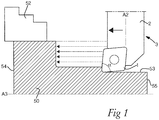
- FIG. 1 show a conventional metal cutting operation by turning using a conventional turning insert 1.
- a metal work piece 50 is clamped by clamping jaws 52, which are connected to a machine comprising a motor (not shown), such as a CNC-machine or a turning lathe.
- the clamping jaws press against an external surface at a first end 54, or clamping end, of the metal work piece 50.
- An opposite second end 55 of the metal work piece 50 is a free end.
- the metal work piece 50 rotates around a rotational axis A3.
- the turning insert 1 is securely and removably clamped in an insert seat or a pocket in a tool body 2.
- the tool body 2 has a longitudinal axis A2, extending from a rear end to a front end, in which the insert seat or pocket is located.
- the tool body 2 and the turning insert 1 together form a turning tool 3.
- the turning tool 3 is moved in relation to the metal work piece 50, commonly designated feed.
- the feed is axial, also called longitudinal feed, i.e. the direction of the feed is parallel to the rotational axis A3.
- a cylindrical surface 53 is formed.
- the turning insert 1 has an active nose with a nose angle a which is 80°, defined as the angle between the main cutting edge and the secondary cutting edge.
- the main cutting edge is behind the nose cutting edge.
- the entering angle for the main cutting edge is over 90°, in Fig. 1 around 95°.
- the entering angle is defined as the angle between the cutting edge and the feed direction.
- the back clearance angle is around 5°.
- the back clearance angle ⁇ is defined as the angle between the secondary cutting edge, which is a trailing edge, and a direction which is opposite, i.e. 180° in relation, to the feed direction.
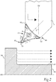
- Fig. 2 show a turning operation, using a turning tool comprising a first turning insert.
- a metal work piece is clamped by clamping jaws (not shown), which are pressed against an external surface at or adjacent to a first end 54 of the metal work piece.
- An opposite second end 55 of the metal work piece is a free end.
- the metal work piece rotates around a rotational axis A3.
- the turning insert seen in top view, is securely and removably clamped in an insert seat or a pocket in tool body 2 by means of a screw 6.
- the tool body 2 has a longitudinal axis A2, extending between a rear end and a front end 44, in which the insert seat or pocket is located.
- the feed is, to a greatest extent, axial, also called longitudinal feed, i.e. the direction of the feed is parallel to the rotational axis A3. In this way, an external cylindrical surface 53 is formed.
- the feed has a radial component, in such a way that the turning insert move along an arc of a circle.
- the turning insert comprises an active nose portion 15, comprising an active nose cutting edge 10.
- the active nose portion 15 further comprises an active first cutting edge which during axial turning parallel to the rotational axis A3 has an entering angle ⁇ 1 which is chosen to be in the range of 10-45°, preferably 20-40°.
- the first cutting edge which is the main cutting edge in the operation, is ahead of the nose cutting edge 10 in the axial feed direction.
- the first cutting edge is a leading edge.
- a second cutting edge, formed on or at the active nose portion 15, is a secondary cutting edge or a trailing edge. If the feed direction would be radial, in such a way that the feed direction would be perpendicular to and away from the rotational axis A3, the second cutting edge would be active at an entering angle ⁇ 2.
- a bisector 7 is defined by the first and second cutting edges. In other words, the bisector is formed between the first and second cutting edges. The first and second cutting edges converge at a point outside the turning insert.
- the bisector of the active nose portion 15 forms an angle ⁇ of 40-50°, relative to the longitudinal axis A2.
- the turning insert comprises two inactive nose portions, comprising two inactive nose cutting edges 10', 10".
- all parts of the turning insert are ahead of the active nose cutting edge 10 in the feed direction.
- chips can be directed away from the metal work piece in a trouble-free manner.
- the turning insert 1 enters into the metal work piece 50 such that the nose cutting edge 10 moves along an arc of a circle.
- the turning insert 1 enters into the metal work piece 50, or goes into cut, such that the chip thickness during entry is constant or substantially constant. At the entry, the depth of cut is increased from zero depth of cut.
- Chip thickness is defined as feed rate multiplied by entering angle.
- the feed rate during entry is preferably less than or equal than 0,50 mm/revolution.
- the chip thickness during entry is preferably less than or equal to the chip thickness during subsequent cutting or machining.
- the cylindrical surface 53, or rational symmetrical surface, generated or formed at least partly by the nose cutting edge in Figs. 1 and 2 has a wavy shape with small peaks and valleys, and the wavy shape is influenced at least partly by the curvature of the nose radius and the feed rate.
- the wave height is less than 0,10 mm, preferably less than 0,05 mm.
- a thread profile is not a cylindrical surface 53 in this sense.
- the turning insert and tool body in Fig. 2 can be seen in alternative machining operations, showing the versatile application area of the turning tool, especially with regard to feed direction.
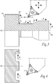
- Fig. 3 shows a machining sequence in six steps.
- Step 1 is a undercutting operation.
- Step 2 is axial turning away from the first end 54 or clamping end of the metal work piece.
- Step 3 is a profiling operation in the form of a feed which has both an axial and a radial component, generating a conical or frustoconical, i.e. tapered, surface.
- Step 4 is an operation similar to operation 2.
- Step 5 is an out-facing operation generation a flat surface located in a plane perpendicular to the rotational axis A3 of the metal work piece.
- Step 6 is an out-facing operation at the second end 55 or free end of the metal work piece.
- Fig 4 shows two machining steps, step 1 and step 2.
- step 1 the radial feed is perpendicular to and towards the rotational axis A3.
- step 2 the radial feed is perpendicular to and away from the rotational axis A3, wherein a flat surface 56 perpendicular to the rotational axis A3 is generated.
- the second cutting edge is active at an entering angle ⁇ 2 which is in the range of 10-45°, preferably 20-40°.
- the direction of rotational of the metal work piece around the rotational axis A3 is in opposite directions for step 1 and 2.
- step 2 the direction of rotation is the same as in Fig. 1-3 .
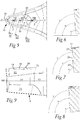
- Fig. 5 shows a top view of a nose portion 15 of the first turning insert, comprising a first 11 and a second 12 cutting edge connected by a convex nose cutting edge 10.
- the first 11 and second 12 cutting edges on or at the same nose portion 15 forms a nose angle ⁇ of 25-50° relative to each other, and the first 11 and second 12 cutting edges converge at a point (not shown) outside of the turning insert.
- a bisector 7 is located between, and at equal distances from, the first 11 and second 12 cutting edges. The bisector 7 intersects the nose cutting edge 10 at the center thereof.
- a protrusion 30 is formed in the top surface of the turning insert, which protrusion has the major extension thereof along the bisector.
- the protrusion comprises a first chip breaker wall 34 facing towards the first cutting edge, and a second chip breaker wall facing the second cutting edge.
- the distance, measured in a direction perpendicular to the first cutting edge 11, and in a plane parallel to a reference plane RP, from the first cutting edge 11 to the first chip breaker wall 34 is increasing away from the nose cutting edge 10. This gives improved chip control especially in a turning operation as in Fig. 2 .
- the protrusion 30, and thus the first chip breaker wall 34 has a shorter extension than the first cutting edge 11.
- Fig. 9 shows a side view of the nose portion in Fig. 5 .
- a bottom surface 9 is located opposite a top surface.
- the reference plane RP is located between and at equidistant length from the top and bottom 9 surfaces. Although the top and bottom surfaces are not flat, the reference plane RP can be positioned such that it is parallel to a plane intersecting the three nose cutting edges.
- a side surface 13 connects the top surface and the bottom surface 9.
- the side surface 13 comprises a first clearance surface 21 adjacent to the first cutting edge 11, a third clearance surface 23 adjacent to the bottom surface 9, and a second clearance surface 22 located between the first clearance surface 21 and the third clearance surface 23. The distance from the first cutting edge 11 to lower border line of the first clearance surface 21, i.e.
- the border line of the first clearance surface 21 located closest to the bottom surface 9, is decreasing away from the nose cutting edge.
- the height, in a direction perpendicular to the reference plane RP, of the first clearance surface 21 is less than the height of the second clearance surface 22, in order to further increase the strength of the first cutting edge 11.
- the height of the first clearance surface 21 is at least 0.3 mm in order to compensate for flank wear of the first cutting edge 11.
- the first cutting edge 11 is sloping towards the bottom surface 9 and the reference plane RP away from the nose cutting edge 10.
- the distance from the first cutting edge 11 to the reference plane RP varies in such a way that that this distance is decreasing at increasing distance from the nose cutting edge 10, at least for a portion of the first cutting edge 11.
- the chip control is improved in axial turning away from the clamping end, as e.g. in an operation as seen in Fig. 2 .
- a distance D1 is measured in a direction perpendicular to the reference plane RP, representing the distance between the top surface of the protrusion 30 and the lowest point of the first cutting edge 11. D1 is 0.28-0.35 mm.
- Figs. 6-8 show sections along the lines VI-VI, VII-VII and VIII-VIII, respectively, in Fig. 5 .
- the sections are perpendicular to the first cutting edge 11 in planes perpendicular to the reference plane RP.
- the angles which the first, second and third clearance surfaces 21, 22, 23 form in relation to a plane parallel to the reference plane RP and intersecting the bottom surface 9 are designated ⁇ , ⁇ and ⁇ , respectively.
- Angle ⁇ is greater than angle ⁇ .
- the second clearance surface 22 has the purpose of increasing the strength of the insert.
- the third clearance surface 23 is adjacent to the bottom surface. Angle ⁇ is greater than angle ⁇ . Angle ⁇ is greater than ⁇ .
- the third clearance surface 23 is convex or substantially convex, seen in cross section as in Figs. 6-8 , in order to further improve the lower diameter range, i.e. the minimum diameter where the turning insert can function in an out facing operation, while minimizing the reduction of insert strength.
- second cutting edge 12, and the side surface 13 adjacent to the second cutting edge 12 are in accordance with the configuration of the first cutting edge 11, and the side surface 13 adjacent to the first cutting edge 11, which has been described in relation to Figs. 5-8 above.
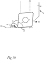
- Fig. 10 illustrates an embodiment of the method to form a surface 53 on a metal work piece according to the invention.
- a known turning insert 1 is provided.
- the turning insert 1 comprises an active nose portion 15.
- the active nose portion 15 comprises a first cutting edge 11, a second cutting edge 12 and a convex nose cutting edge 10 connecting the first 11 and second 12 cutting edges.
- a nose angle ⁇ formed between the first 11 and second 12 cutting edges is less than or equal to 85°.
- the nose angle ⁇ is preferably at least 25°. In Fig. 10 , the nose angle ⁇ is 80°.
- the second cutting edge 12 forms a back clearance angle ⁇ of more than 90° in a feed direction 99.
- the back clearance angle ⁇ is at least 100°.
- the back clearance angle ⁇ is less than 120°.
- the back clearance angle ⁇ is constant in relation to the feed direction 99 during the formation of the surface 53.
- All parts of the turning insert 1 are ahead of the active or surface generating nose cutting edge 10 in the feed direction 99.
- all parts of a top surface of the turning insert are ahead of a trailing portion of the nose cutting edge in the feed direction.
- One first point of the nose cutting edge 10 is the part of the turning insert 1 which is located closest to the rotational axis of the metal work piece.
- Said first point of the nose cutting edge 10 is located on the same side of a bisector as the first cutting edge 11, where the bisector is a line which is between the first and second cutting edges 11, 12 at equal distance from the first and second cutting edges 11, 12.
- Said second point of the nose cutting edge 10 is located on the same side of the bisector as the second cutting edge 12.
- the first cutting edge 11 and the second cutting edge 12 are located on opposite sides of the convex nose cutting edge 10.
- the first, second and nose cutting edges 11, 12, 10 are formed at borders of a top surface of the turning insert 1, which top surface comprises a rake face.
- the expression "positioning all parts of the turning insert ahead of the nose cutting edge in the feed direction” thus can alternatively be formulated as "positioning all parts of a top surface of the turning insert ahead of a trailing portion of the nose cutting edge in the feed direction".
- All parts of the turning tool 3, comprising the turning insert 1 and a tool body 2, is ahead of the active or surface generating nose cutting edge 10 in the feed direction.
- all parts of the tool body 2 is ahead of the nose cutting edge 10 in the feed direction 99.
- the turning tool 3 is clamped or connected to a turning lathe, such as a CNC-machine or CNC-lathe (not shown).
- a metal work piece, on which the surface 53 is formed, rotates around a rotational axis (not shown).
- the tool body 2 comprises a front end and a rear end, a main extension along a longitudinal axis A2 extending from the front end to the rear end, an insert seat formed in the front end in which the turning insert 1 is mounted,
- the longitudinal axis A2 of the tool body 2 is perpendicular to the rotational axis of the metal work pece.
- the turning insert 1 moves in a direction, defined by the feed direction 99, which is parallel to or at an angle less than 45° relative to the rotational axis.
- the feed direction 99 is parallel to the rotational axis of the metal work piece.
- the first cutting edge 11 is active and ahead of the nose cutting edge 10 in the feed direction 99.
- the first cutting edge is active, i.e.
- the first cutting edge 11 is a leading edge.
- the second cutting edge 12 is a trailing edge.
- the surface 53 is at least partly is formed by the nose cutting edge 10.
- the surface 53 which is formed is a rotational symmetrical surface, i.e.
- each portion of the rotational symmetrical surface 53 is located at a constant distance from the rotation axis of the metal work piece, where a constant distance is a distance which is within 0.10 mm, preferably within 0.05 mm.
- the rotational symmetrical surface 53 can be in the form of e.g. a cylindrical surface or a conical surface or a frustoconical surface or a tapered surface.
- the rational symmetrical surface 53 generated or formed at least partly by the nose cutting edge 10 has a wavy shape with small peaks and valleys, and the wavy shape is influenced at least partly by the curvature of the nose radius and the feed rate.
- the wave height is less than 0.10 mm, preferably less than 0.05 mm.
- the active nose cutting edge 10 is the part of the turning insert 1 and the part of the turning tool 3 which is closest to the rotational axis of the metal work piece.
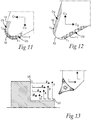
- Fig. 11 shows the principle of conventional turning, where C1 represents the feed direction in Fig. 1 , and D1 represents the wear on or at a nose portion from such operation. C3 represents a conventional facing operation, i.e.
- the second cutting edge 12 is the main cutting edge in C1 feed direction.
- the first cutting edge 11 is the main cutting edge in C3 feed direction.
- a convex nose cutting edge 10 connects the first and second cutting edges 11, 12.
- Transition points T1, T2 represent the transition between the nose cutting edge 10 and the first 11 and second 12 cutting edge, respectively.
- the wear D1, D3, is dependent on both the depth of cut and the feed rate. However, it is clear that D1 and D3 overlap, resulting in high wear at the nose cutting edge 10, or at least at a center portion of the nose cutting edge 10.
- Fig. 12 shows the principle of another embodiment.
- C2 represents the main feed direction in Fig. 2 , or the main feed direction in pass 2, 4, 6 and 8 in Fig. 13 , i.e. an axial feed direction away from the clamping end of the metal work piece.
- D2 represents the wear on or at a nose portion from such operation.
- C4 represents an out-facing operation, i.e. feed perpendicular to and away from the rotational axis A3, as seen in the main feed directions in pass 1, 3, 5 and 7 in Fig. 10 .
- D4 represents the wear on or at a nose portion from such operation.
- the second cutting edge 12 is the main cutting edge in C4 feed direction.
- the first cutting edge 11 is the main cutting edge in C2 feed direction.
- a convex nose cutting edge 10 connects the first and second cutting edges 11, 12.
- Transition points T1, T2 represent the transition between the nose cutting edge 10 and the first 11 and second 12 cutting edge, respectively.
- the wear D2, D4 is dependent on both the depth of cut and the feed rate. However, it is clear that D2 and D4 do not overlap, or at least overlap to a lesser degree than in Fig. 11 , resulting in reduced wear at the nose cutting edge 10, or at least reduced wear at a center portion of the nose cutting edge 10.
- the wear of the first and second cutting edges 11, 12 has a wider range, i.e. is distributed over a longer distance, compared to Fig. 11 .
- the chip thickness in Fig. 12 will be thinner and therefor give relatively small wear.
- the area of D2 is equal to the area of D3
- the area of D1 is equal to the area of D4.
- Fig. 13 show an example of a machining sequence using the first turning insert.
- Left-hand side is the clamping end of the metal work piece.
- a 90° corner comprising a cylindrical surface 53 and a flat surface 56 is formed by turning.
- a sequence of steps 1-8 is shown.
- the entry for each step is shown as perpendicular to the main feed direction of each step.
- the main feed direction in steps 1, 3, 5 and 7 is perpendicular to and away from the rotational axis A3.
- the main feed direction in steps 2, 4, 6 and 8 is parallel to the rotational axis A3 and away from the clamping end.
- the entry for each cut is preferably as described in connection to Fig. 2 .
- the wear of the turning insert 1 after the sequence of steps showed in Fig. 13 is similar or identical to the wear shown in Fig. 12 .
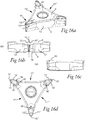
- Figs. 16a-17c further describes the first turning insert, as well as a turning tool 3 which comprises the turning insert 1 and a tool body 2.
- the turning insert 1 comprises a top surface 8, which is or comprises a rake face, and an opposite bottom surface 9, functioning as a seating surface.
- a reference plane RP is located parallel to and between the top surface 8 and the bottom surface 9.
- a center axis A1 extends perpendicular to the reference plane RP and intersects the reference plane RP, the top surface 8 and the bottom surface 9.
- a hole, for a screw, having openings in the top surface 8 and the bottom surface 9 is concentric with the center axis A1.
- the turning insert 1 comprises side surfaces 13, 13', 13", functioning as clearance surfaces, connecting the top surface 8 and the bottom surface 9.
- Each nose portion 15, 15', 15" comprises a first cutting edge 11, a second cutting edge 12 and a convex nose cutting edge 10 connecting the first 11 and second 12 cutting edges.
- the nose cutting edges 10, 10', 10" are located at a largest distance from the center axis A1, i.e. at a larger distance from the center axis A1 than all other parts of the turning insert.
- the first 11 and second 12 cutting edges on or at the same nose portion 15 forms a nose angle ⁇ of 25-50° relative to each other, in Fig.
- the nose angle ⁇ is 35°.
- a side view such as in Fig. 16b
- at least a portion of the first and second cutting edges 11, 12 on or at each nose portion 15, 15', 15" slopes towards the bottom surface, such that in a side view, the first and second cutting edges 11, 12 have the highest points thereof bordering to the nose cutting edge 10 on or at the same nose portion 15.
- the distance from the first cutting edge 11 and the second cutting edge 12 to the reference plane RP varies in such a way that that this distance is decreasing at increasing distance from the nose cutting edge 10.
- the first and second cutting edges 11, 12 are linear or straight, or substantially linear or straight in a top view.
- Bisectors 7, 7', 7" extend equidistantly from each pair of first 11, 11', 11" and second 12, 12', 12" cutting edges. Each bisector 7, 7', 7" intersects the center axis A1. Indentations 17, 17', 17" are formed between each pair of nose cutting edges 10, 10', 10".
- the bottom surface 9, seen in Figs. 18a and 18b comprises rotation prevention means, with the purpose of reducing the tendency for the turning insert 1 to rotate around the center axis A1 during cutting, in the form of three grooves 40, 40', 40", each groove 40, 40', 40" having a main extension in the same direction as the bisector 7, 7', 7" located adjacent the closest first 11 and second 12 cutting edges.
- Each groove 40, 40', 40" comprises two seating surfaces preferably at an obtuse angle, 100-160°, in relation to each other.
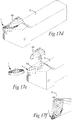
- the turning insert 1 is intended to be securely clamped, by clamping means such as a screw or a top clamp, in an insert seat 4 located at a front end of a tool body 2, as seen in Fig. 17a .
- the contact between the insert seat 4 and the turning insert will now be described, see the shaded areas in Fig. 17c and Fig. 17a .
- the active nose cutting portion 15 is the part of the insert where groove 40 is located in Fig. 17c .
- the two seating surfaces of groove 40 are in contact with two surfaces of a ridge 90 in the bottom of the insert seat 4.
- each other groove 40', 40" the surfaces located at the largest distance from the active nose cutting edge 10, are in contact with bottom surfaces 93, 94 in the bottom of the insert seat 4. At least portions of the side surface 13 located at the greatest distance from the active nose cutting edge 10 may be in contact with rear seating surfaces 91, 92 formed at a rear end of the insert seat 4.
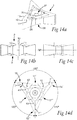
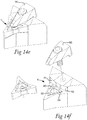
- Figs. 14a-f show a second turning insert 1 as well as a turning tool 3 which comprises the turning insert 1 and a tool body 2.
- the turning insert 1 comprises a top surface 8, which is or comprises a rake face, and an opposite bottom surface 9, functioning as a seating surface.
- the top 8 and bottom 9 surfaces are identical. This means that while in a first position, the top surface 8 functions as a rake surface, when the insert is turned upside down, the same surface is now functioning as a seating surface.
- a reference plane RP is located parallel to and between the top surface 8 and the bottom surface 9.
- a center axis A1 extends perpendicular to the reference plane RP and intersects the reference plane RP, the top surface 8 and the bottom surface 9.
- a hole for a screw, having openings in the top surface 8 and the bottom surface 9 is concentric with the center axis A1.
- the turning insert 1 comprises side surfaces 13, 13', 13", functioning as clearance surfaces, connecting the top surface 8 and the bottom surface 9.
- Three nose portions 15, 15', 15" are formed symmetrically relative to or around the center axis A1.
- the nose portions 15, 15', 15" are identical.
- Each nose portion 15, 15', 15" comprises a first cutting edge 11, a second cutting edge 12 and a convex nose cutting edge 10 connecting the first 11 and second 12 cutting edges.
- the nose cutting edges 10, 10', 10" are located at a largest distance from the center axis A1, i.e. at a larger distance from the center axis A1 than all other parts of the turning insert.
- the first 11 and second 12 cutting edges on or at the same nose portion 15 forms a nose angle ⁇ of 25-50° relative to each other, in this case 45°.
- a side view seen in Fig. 14b , at least a portion of the first and second cutting edges 11, 12 on or at each nose portion 15, 15', 15" slopes towards the bottom surface, such that in a side view, the first and second cutting edges 11, 12 has the highest points thereof adjacent to the nose cutting edge 10 on or at the same nose portion 15.
- the distance from the first cutting edge 11 and the second cutting edge 12 to the reference plane RP varies in such a way that that this distance is decreasing at increasing distance from the nose cutting edge 10.
- the first and second cutting edges 11, 12 are linear or straight, or substantially linear or straight in a top view.
- Bisectors 7, 7', 7" extend equidistantly from each pair of first 11, 11', 11" and second 12, 12', 12" cutting edges.
- Each bisector 7, 7', 7" intersects the center axis A1.
- Indentations 17, 17', 17" are formed between each pair of adjacent nose cutting edges 10, 10', 10".
- the turning insert 1 comprises rotation prevention means in the form of a set of surfaces 41, 42, 43, 44, where each surface 41, 42, 43, 44 extends in a plane which forms an angle of 5-60° in relation to the reference plane RP.
- the set of surfaces 41, 42, 43, 44 are formed at a central ring-shaped protrusion 30, extending around the center axis A1.
- the first chip breaker wall 34 can be a part of the set of surfaces 41, 42, 43, 44.
- An alternative solution is to arrange the first chip breaking wall 34 as part of a further protrusion (not shown) at a greater distance from the center axis A1.
- Fig. 14e show one possible clamping mode of the turning insert 1 by means of a clamp 95, which presses the insert and keeps the insert in the insert seat 4 of the tool body 2.
- the side surface 13 located at a greatest distance from the active nose cutting edge 10 comprises two surfaces, which are pressed against rear surfaces 91, 92 of the insert seat 4.
- the set of surfaces 41, 42, 43, 44 comprises two front surfaces 41, 42, which are in contact with surfaces of a front portion 90 of the bottom of the insert seat 4. Front in this context is between the center axis A1 and the active nose cutting edge 10.
- the set of surfaces 41, 42, 43, 44 further comprises two rear surfaces 43, 44, which are pressed against rear bottom surfaces 93, 94 which are located in the bottom surface of the insert seat 4, between the front portion 90 and the rear surfaces 91, 92 of the insert seat 4.
- Fig. 2a show turning using a third turning insert.
- a metal work piece is clamped by clamping jaws (not shown), which are pressed against an external surface at a first end 54, or clamping end, of the metal work piece.
- An opposite second end 55 of the metal work piece is a free end.
- the metal work piece rotates around a rotational axis A3.
- the turning insert seen in top view, is securely and removably clamped in an insert seat or a pocket in tool body 2 by means of a screw.
- the tool body 2 has a longitudinal axis A2, extending from a rear end to a front end, in which the insert seat or pocket is located.
- the feed is, to a greatest extent, axial, also called longitudinal feed, i.e. the direction of the feed is parallel to the rotational axis A3. In this way, an external cylindrical surface 53 is formed.
- the feed has a radial component, in such a way that the turning insert move along an arc of a circle.
- the turning insert comprises two opposite and identical nose portions 15, 15' formed 180° relative each other around a center axis of the turning insert 1.
- Each nose portion 15, 15' comprises a first cutting edge 11, a second cutting edge 12 and a convex nose cutting edge 10 connecting the first 11 and second 12 cutting edges.
- the bisector of the active nose portion 15 forms an angle ⁇ , 40-50°, relative to the longitudinal axis A2.
- the first 11 and second 12 cutting edges on the same nose portion 15 forms a nose angle ⁇ of 70-85° relative to each other, which in Fig. 2a is 80°.
- a third convex cutting edge 60 is formed adjacent to the first cutting edge 11.
- a fourth cutting edge 61 is formed adjacent to the third cutting edge 60, further away from the nose cutting edge 10.
- a fifth convex cutting edge 62 is formed adjacent to the second cutting edge 12.
- a sixth cutting edge 63 is formed adjacent to the fifth cutting edge 62, further away from the nose cutting edge 10.
- the first, second, fourth and sixth cutting edges 11, 12, 61, 63 are linear or straight, or substantially linear or straight. The main feed direction, towards the right in Fig.
- the fourth cutting edge 61 is active at an entering angle ⁇ 1 of 10-45°, preferably 20-40°, which in Fig. 2a is 30°.
- the fourth cutting edge 63 is the main cutting edge in said feed direction, i.e. the majority of the chips are cut by the fourth cutting edge 63, at least at moderate to high depth of cut.
- third cutting edge 60, the first cutting edge 11 and the nose cutting edge 10 are also active.
- the first cutting edge is ahead of the nose cutting edge 10 in said axial feed direction. All parts of the turning insert are ahead of the active nose cutting edge 10 in said feed direction.
- the second cutting edge 11, formed on the active nose portion 15, is inactive.
- chips can be directed away from the metal work piece in a trouble-free manner, especially compared to the machining shown in Fig. 1 where the feed is towards the clamping end and towards a wall surface.
- the turning insert 1 enters into the metal work piece 50 such that the nose cutting edge 10 moves along an arc of a circle.
- the turning insert 1 enters into the metal work piece 50, or goes into cut, such that the chip thickness during entry is constant or substantially constant.
- the depth of cut is increased from zero depth of cut.
- Chip thickness is defined as feed rate multiplied by entering angle.
- the chip thickness can be constant or substantially constant.
- the feed rate during entry is preferably less or equal than 0,50 mm/revolution.
- the chip thickness during entry is preferably less than or equal to the chip thickness during subsequent cutting or machining. If the feed direction would be radial, in such a way that the feed direction would be perpendicular to and away from the rotational axis A3, the sixth cutting edge 63 would be active at an entering angle ⁇ 2 of 10-45°, preferably 20-40°.
- Step 1 and 2a has a wavy shape with small peaks and valleys, and the wavy shape is influenced at least partly by the curvature of the nose radius and the feed rate.
- the wave height is less than 0,10 mm, preferably less than 0,05 mm.
- a thread profile is not a cylindrical surface 53 in this sense.
- the turning insert and tool body in Fig. 2a can be seen in several machining operations, showing the versatile application area of the turning tool, especially with regard to feed direction.
- a machining sequence in six steps is shown.
- Step 1 is a undercutting operation
- Step 2 is axial turning away from the first end 54, or clamping end, of the metal work piece.
- Step 3 is a profiling operation in the form of a feed which has both an axial and a radial component, generating a conical or frustoconical surface.
- Step 4 is an operation similar to step 2.
- Step 5 is an out-facing operation generation a flat surface located in a plane perpendicular to the rotational axis A3 of the metal work piece.
- Step 6 is an out-facing operation at the second end 55, or free end, of the metal work piece.
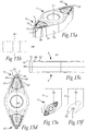
- Figs. 15a-f and Figs.17d-f further describes the third turning insert 1, as well as a turning tool 3 which comprises the turning insert 1 and a tool body 2.
- the turning insert 1 comprises a top surface 8, which is or comprises a rake face 14, and an opposite bottom surface 9, functioning as a seating surface.
- a reference plane RP is located parallel to and between the top surface 8 and the bottom surface 9.
- a center axis A1 extends perpendicular to the reference plane RP and intersects the reference plane RP, the top surface 8 and the bottom surface 9.
- a screw hole having openings in the top surface 8 and the bottom surface 9 is concentric with the center axis A1.
- the third turning insert 1 comprises side surfaces 13, functioning as clearance surfaces, connecting the top surface 8 and the bottom surface 9.
- Two opposite nose portions 15, 15' are formed symmetrically relative to or around the center axis A1.
- the nose portions 15, 15' are identical.
- Each nose portion 15, 15' comprises a first cutting edge 11, a second cutting edge 12 and a convex nose cutting edge 10 connecting the first 11 and second 12 cutting edges.
- Each nose portion 15, 15' further comprises a third convex cutting edge 60, formed adjacent to the first cutting edge 11, and a fourth cutting edge 61 formed adjacent to the third cutting edge 60, further away from the nose cutting edge 10.
- Each nose portion 15, 15' further comprises a fifth convex cutting edge 62 formed adjacent to the second cutting edge 12, and a sixth cutting edge 63 formed adjacent to the fifth cutting edge 62, further away from the nose cutting edge 10.
- the first, second, fourth and sixth cutting edges 11, 12, 61, 63 are linear or straight, or substantially linear or straight.
- the nose cutting edges 10, 10' are located at a largest distance from the center axis A1, i.e. at a larger distance from the center axis A1 than all other parts of the turning insert.
- the first 11 and second 12 cutting edges on the same nose portion 15 forms a nose angle ⁇ of 75-85° relative to each other, in Fig. 15d the nose angle ⁇ is 80°.
- a side view such as in Fig.
- the fourth and sixth cutting edges 61, 63 on each nose portion 15, 15', 15" slopes towards the bottom surface 9, such that in a side view, the fourth and sixth cutting edges 61, 63 has the highest points thereof closer to the nose cutting edge 10 on the same nose portion 15.
- the distance from the fourth cutting edge 61 and the sixth cutting edge 63 to the reference plane RP varies in such a way that that this distance is decreasing at increasing distance from the nose cutting edge 10.
- first, second third and fifth cutting edges 11, 12, 60, 62 are sloping towards the bottom surface 9 in a corresponding manner, such that in relation to the bottom surface 9, the nose cutting edge 10 is further away than the first and second cutting edges 11, 12, which in turn are further away than the third and fifth cutting edges 60, 62, which in turn are further away than the fourth and sixth cutting edges 61, 63.
- Bisectors 7, 7' extend equidistantly from each pair of first 11, 11' and second 12, 12' cutting edges. Each bisector 7, 7' intersects the center axis A1, and the bisectors 7, 7' extend in a common direction.
- the bottom surface 9 is identical to the top surface 8. In a top view, as in Fig.
- the fourth cutting edge 61 forms an angle ⁇ of 0-34° relative to the bisector 7, which in Fig. 15d is 10-20°.
- the top surface 8 comprises protrusions 30 comprising a first chip breaker wall 34 facing the forth cutting edge 61. The distance from the fourth cutting edge 61 to the first chip breaker wall 34 is increasing away from the nose cutting edge 10.
- the protrusions 30 are intended to function as seating surfaces, and the top surface of each protrusion is flat and parallel to the reference plane RP.
- the protrusions 30 are the part of the turning insert 1 which are located at the greatest distance from the reference plane RP.
- the protrusion comprises a second chip breaker wall facing the sixth cutting edge.
- the distance, from the fourth cutting edge 61 to the first chip breaker wall 34, is measured in a direction perpendicular to the fourth cutting edge 61, and in a plane parallel to the reference plane RP, to the first chip breaker wall 34.
- the protrusion 30, and thus the first chip breaker wall 34 does not necessarily have to extend along the whole length of the fourth cutting edge 61. Still, the distance from the fourth cutting edge 61 to the first chip breaker wall 34 is increasing at the portion of the fourth cutting edge 61 where perpendicular to this fourth cutting edge 61, the first chip breaker wall 34 extends.
- a distance D1 measured in a plane perpendicular to the reference plane RP between the top surface of the protrusion 30 and the lowest point of the forth cutting edge 61 is 0.28-0.35 mm.
- Bumps 80, or protrusions, are formed in the top surface 8.
- the bumps 80 are located at a distance, greater than 0.3 mm and less than 3.0 mm, from the fourth cutting edge 61.
- the bumps 80 are located between the fourth cutting edge 61 and the first chip breaker wall 34.
- the bumps 80 have a non-circular shape in top view, such that a major extension, which is 0.8-3.0 mm, of the bumps is in a direction substantially perpendicular to or perpendicular to the fourth cutting edge 61.
- the minor extension of the bumps perpendicular to the major extension is 0.5-2.0 mm.
- the bumps 80, or protrusions are portions of the top surface 8 which extends away from the reference plane in relation to the surrounding area.
- the bumps 80 preferably have an elliptic or oval or substantially elliptic or oval shape.
- the bumps 80 are separated from each other.
- the bumps 80 preferably are located at a constant distance from each other.
- the bumps 80 preferably are located at a constant distance from the fourth cutting edge 61. In the first embodiment, there are 5 bumps adjacent to the fourth cutting edge. It is preferred to have 2-10 bumps adjacent to the fourth cutting edge.
- the third turning insert there are 2-3 bumps 80, located perpendicular to and having an major extension in a direction perpendicular to the third cutting edge 60, and at least one further bump 80, in the first embodiment 1-2 bumps 80, located perpendicular to and having an major extension in a direction perpendicular to the first cutting edge 11.
- the third turning insert 1 is mirror symmetric on opposite sides of the bisectors 7, 7'. Therefore, bumps 80 are formed in a corresponding manner at a distance from the second, fifth and sixth cutting edges 12, 62, 63.
- the chip when the depths of cut is such that the first cutting edge 11 is active and that the fourth cutting edge 61 is inactive. At such low depth of cut, the chip is very thin, due to the low entering angle by the first cutting edge 11, and the bump or bumps 80, closest to the first cutting edge 11, function as chip breakers.
- the major extension of the bumps 80 gives the effect that the time, until the wear of the bumps 80 reduces the effect of the bumps 80 on the chips, is increased.
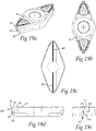
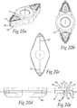
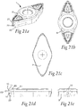
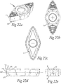
- Figs. 18-22 a-e shows a fourth, fifth, sixth, seventh and eighth type of turning insert, respectively, suitable for the method according to the invention. These inserts differ from the third insert only with regards to the bottom surface and the side surfaces.
- the fourth, fifth, sixth, seventh and eighth turning inserts 1, shown in Figs. 18-22 a-e respectively, have the same or identical shape, form, dimension, value and interrelations between features and elements as the third turning insert with regards to the top surface 8, reference plane RP, screw hole, first cutting edge 11, nose cutting edge 10, second cutting edge 12, third cutting edge 60, fourth cutting edge 61, fifth cutting edge 62, sixth cutting edge 63, nose angle ⁇ , bisector 7, angle ⁇ , rake face 14, protrusion 30, first chip breaker wall 34, second chip breaker wall, distance D1 and bumps 80.
- the fourth, fifth, sixth and seventh turning inserts 1, shown in Figs. 18-21 a-e are formed such that a first side surface 13 comprises a first clearance surface 21 adjacent to the first cutting edge 11, a third clearance surface 23, and a second clearance surface 22 located between the first clearance surface 21 and the third clearance surface 23.
- the angle which the second clearance surface 22 forms in relation to the bottom surface 9 measured in a plane perpendicular to the first cutting edge 11 is greater than the angle which the third clearance surface 23 forms in relation to the bottom surface measured in a plane perpendicular to the first cutting edge 11.
- the angle which the second clearance surface 22 forms in relation to the bottom surface 9 measured in a plane perpendicular to the first cutting edge 11 is greater than the angle which the first clearance surface 21 forms in relation to the bottom surface measured in a plane perpendicular to the first cutting edge 11.
- each nose portion 15, 15' are configured symmetrically in relation to a plane perpendicular to the reference plane RP and comprising the bisector 7.
- the clearance surface adjacent to the second cutting edge 12 is formed or arranged in a corresponding manner.
- the bottom surface 9 comprises rotation prevention means 40, in order to reduce movement of the turning insert 1 relative to the insert seat 4 during machining.
- the rotation prevention means 40 are in the form of two grooves 40, 40' having a common major extension, which major extension is corresponding to the extension of the bisectors 7, 7'.
- the bottom surface 9 comprises rotation prevention means 40, in order to reduce movement of the turning insert 1 relative to the insert seat 4 during machining.
- the rotation prevention means 40 are in the form of two grooves 40, 40' having a common major extension, which major extension is corresponding to the extension of the bisectors 7, 7'.
- Each groove 40, 40' comprises two surfaces which are form an obtuse angle, in the range of 100-160°, in relation to each other.
- Figs. 20a-e show a sixth turning insert 1.
- the bottom surface 9 comprises rotation prevention means 40, in order to reduce movement of the turning insert 1 relative to the insert seat 4 during machining.
- the rot ation prevention means 40 are in the form of two ridges 40, 40' having a common major extension, which major extension is corre sponding to the extension of the bisectors 7, 7'.
- the bottom surface 9 comprises a flat surface 9, which is parallel to the reference plane RP.
- the bottom surface 9 comprises a flat surface 9, which is parallel to the reference plane RP.
- the flat surface 9 is ring-shaped around the center axis of the turning insert.
- a first side surface 13 comprises a first clearance surface 21 adjacent to the first cutting edge 11 and a third clearance surface 23.
- the third clearance surface 23 borders to the bottom surface 9.
- the angle which the first clearance surface 21 forms in relation to the bottom surface 9 measured in a plane perpendicular to the first cutting edge 11 is greater than the angle which the third clearance surface 23 forms in relation to the bottom surface measured in a plane perpendicular to the first cutting edge 11.
- the clearance surface adjacent to the second cutting edge 12 is formed or arranged in a corresponding manner.
- the advantages from the clearance surface arrangements are that out-facing can be performed at small metal work piece diameters, and that larger depth of cut is possible in out-facing.
- the protrusion 30 comprises grooves formed in the top surface of the protrusion 30.
- the grooves have a major extension perpendicular to the bisector 7.
Landscapes
- Engineering & Computer Science (AREA)
- Mechanical Engineering (AREA)
- Turning (AREA)
- Milling Processes (AREA)
- Cutting Tools, Boring Holders, And Turrets (AREA)
Claims (17)
- Procédé pour former une surface (53) sur une pièce d'ouvrage métallique (50) comprenant une première étape d'usinage consistant à- fournir une plaquette de tournage (1) comprenant une première arête de coupe (11), une deuxième arête de coupe (12) et une arête de coupe de bec convexe (10) reliant les première (11) et deuxième (12) arêtes de coupe,- fournir un outil de tournage (3) comprenant la plaquette de tournage (1) et un corps d'outil (2), le corps d'outil (2) présentant une extrémité avant (44) et une extrémité arrière (45), une extension principale le long d'un axe longitudinal (A2) s'étendant depuis l'extrémité avant (44) jusqu'à l'extrémité arrière (45), et un siège de plaquette formé dans l'extrémité avant (44) dans lequel la plaquette de tournage (1) est montée,- sélectionner un angle de bec (α) formé entre les première (11) et deuxième (12) arêtes de coupe de sorte à ce qu'il soit inférieur ou égal à 85°,où le procédé comprend les étapes supplémentaires consistant à- adapter l'orientation de la deuxième arête de coupe (12) de telle sorte qu'elle forme un angle de dépouille arrière (ψ) de plus de 90° selon une direction d'avance (99),- positionner toutes les parties de la plaquette de tournage (1) devant l'arête de coupe de bec (10) selon la direction d'avance (99),- régler l'axe longitudinal (A2) du corps d'outil (2) à un angle supérieur à zéro mais inférieur ou égal à 90° par rapport à un axe de rotation (A3) de la pièce d'ouvrage métallique (50),- faire tourner la pièce d'ouvrage métallique (50) autour de l'axe de rotation (A3) selon un premier sens,- déplacer la plaquette de tournage (1) selon une direction parallèle à l'axe de rotation (A3) ou formant un angle inférieur à 45° par rapport à celui-ci de telle sorte que la première arête de coupe (11) est active et devant l'arête de coupe de bec (10) selon la direction d'avance (99) et de telle sorte que la surface (53) est au moins en partie formée par l'arête de coupe de bec (10), caractérisé en ce que,le procédé comprend en outre l'étape consistant à- régler l'angle de dépouille arrière (ψ) de sorte à ce qu'il soit constant par rapport à la direction d'avance (99) durant la formation de la surface (53).
- Procédé selon la revendication 1, dans lequel la première étape d'usinage comprend en outre les étapes consistant à fixer la pièce d'ouvrage métallique (50) au niveau d'une première extrémité (54), régler l'arête de coupe de bec (10) à une plus courte distance de la première extrémité (54) que toutes les autres parties de la plaquette de tournage (1) et déplacer la plaquette de tournage (1) selon une direction s'éloignant de la première extrémité (54).
- Procédé selon l'une quelconque des revendications précédentes, dans lequel la première étape d'usinage comprend en outre l'étape consistant à agencer la première arête de coupe (11) de telle sorte que la première arête de coupe (11) coupe des copeaux de métal sur la pièce d'ouvrage métallique (50) à un angle d'entrée κ1 allant de 10 à 45°.
- Procédé selon la revendication 1 ou 2, dans lequel la première étape d'usinage comprend en outre l'étape consistant à faire en sorte que la plaquette de tournage (1) comprenne une troisième arête de coupe convexe (60) adjacente à la première arête de coupe (11) et une quatrième arête de coupe (61) adjacente à la troisième arête de coupe (60), le procédé comprenant en outre l'étape consistant à agencer la quatrième arête de coupe (61) de telle sorte que la quatrième arête de coupe (61) coupe des copeaux de métal sur la pièce d'ouvrage métallique (50) à un angle d'entrée κ1 allant de 10 à 45°.
- Procédé selon l'une quelconque des revendications précédentes, dans lequel la première étape d'usinage comprend en outre l'étape consistant à faire pénétrer la plaquette de tournage (1) dans la pièce d'ouvrage métallique (50) de telle sorte que l'arête de coupe de bec (10) se déplace le long d'un arc de cercle.
- Procédé selon l'une quelconque des revendications précédentes, dans lequel la première étape d'usinage comprend en outre l'étape consistant à faire pénétrer la plaquette de tournage (1) dans la pièce d'ouvrage métallique (50) de telle sorte que l'épaisseur de copeaux durant la pénétration est constante ou sensiblement constante.
- Procédé selon l'une quelconque des revendications précédentes, dans lequel la surface (53) est une surface cylindrique externe, et où le déplacement de la plaquette de tournage (1) se fait selon une direction parallèle à l'axe de rotation (A3).
- Procédé selon l'une quelconque des revendications précédentes, où le procédé comprend en outre l'étape consistant à agencer la plaquette de tournage (1) de telle sorte que la plaquette de tournage (1) comprend une surface supérieure (8), une surface inférieure opposée (9), où un plan de référence (RP) est positionné parallèle aux et entre les surface supérieure (8) et surface inférieure (9), le procédé comprend en outre l'étape consistant à agencer la première arête de coupe (11) de telle sorte que la distance entre la première arête de coupe (11) et le plan de référence (RP) diminue à mesure que la distance à compter de l'arête de coupe de bec (10) augmente.
- Procédé selon l'une quelconque des revendications 4 à 8, où le procédé comprend en outre l'étape consistant à agencer la plaquette de tournage (1) de telle sorte que la plaquette de tournage (1) comprend une surface supérieure (8), une surface inférieure opposée (9), où un plan de référence (RP) est positionné parallèle aux et entre les surface supérieure (8) et surface inférieure (9), le procédé comprend en outre l'étape consistant à agencer la quatrième arête de coupe (61) de telle sorte que la distance entre la quatrième arête de coupe (61) et le plan de référence (RP) diminue à mesure que la distance à compter de l'arête de coupe de bec (10) augmente.
- Procédé selon l'une quelconque des revendications précédentes, comprenant en outre l'étape consistant à positionner toutes les parties du corps d'outil (2) devant l'arête de coupe de bec (10) selon la direction d'avance (99).
- Procédé selon l'une quelconque des revendications précédentes, comprenant en outre une deuxième étape d'usinage consistant à déplacer la plaquette de tournage (1) selon une direction s'éloignant de l'axe de rotation (A3) de telle sorte que la deuxième arête de coupe (12) coupe des copeaux sur la pièce d'ouvrage métallique (50), et de telle sorte qu'une surface (56) perpendiculaire à l'axe de rotation (A3) de la pièce d'ouvrage métallique (50) est formée.
- Procédé selon la revendication 11, comprenant en outre l'étape consistant à alterner selon une certaine séquence les première et deuxième étapes d'usinage, de telle sorte qu'un coin comprenant deux surfaces (53, 56) est formé.
- Procédé selon la revendication 11 ou 12, comprenant en outre l'étape consistant à alterner selon une certaine séquence les première et deuxième étapes d'usinage, de telle sorte qu'un coin externe de 90° comprenant deux surfaces de paroi (53, 56) est formé, où une surface de paroi est une surface cylindrique extérieure (53) et une surface de paroi (56) est perpendiculaire à l'axe de rotation (A3) de la pièce d'ouvrage métallique (50).
- Procédé selon l'une quelconque des revendications précédentes, le procédé comprenant en outre une troisième étape d'usinage, comprenant les étapes consistant à faire tourner la pièce d'ouvrage métallique (50) autour de l'axe de rotation (A3) selon un second sens, où le second sens de rotation est opposé au premier sens de rotation, et à déplacer la plaquette de tournage (1) selon une direction allant vers l'axe de rotation (A3) de telle sorte que la deuxième arête de coupe (12) coupe des copeaux sur la pièce d'ouvrage métallique (50).
- Procédé selon l'une quelconque des revendications précédentes, comprenant l'étape consistant à agencer la plaquette de tournage (1) de telle sorte qu'une bissectrice (7) s'étendant à équidistance des première (11) et deuxième (12) arêtes de coupe forme un angle θ allant de 35 à 55° par rapport à l'axe longitudinal (A2) du corps d'outil (2).
- Procédé selon la revendication 15, comprenant l'étape consistant à agencer la première arête de coupe (11) à une distance de l'axe longitudinal (A2) du corps d'outil (2) inférieure à la distance entre la deuxième arête de coupe (12) et l'axe longitudinal (A2) du corps d'outil (2).
- Utilisation d'une plaquette de tournage (1) dans le cadre du procédé selon l'une quelconque des revendications précédentes.
Priority Applications (1)
| Application Number | Priority Date | Filing Date | Title |
|---|---|---|---|
| EP20193770.3A EP3778077A1 (fr) | 2015-10-09 | 2016-09-07 | Procédé pour usiner une pièce métallique par tournage |
Applications Claiming Priority (2)
| Application Number | Priority Date | Filing Date | Title |
|---|---|---|---|
| EP15189176.9A EP3153257B1 (fr) | 2015-10-09 | 2015-10-09 | Procédé pour usiner une pièce métallique par tournage |
| PCT/EP2016/071101 WO2017060027A1 (fr) | 2015-10-09 | 2016-09-07 | Procédé pour usiner une pièce à travailler métallique par tournage |
Related Child Applications (2)
| Application Number | Title | Priority Date | Filing Date |
|---|---|---|---|
| EP20193770.3A Division EP3778077A1 (fr) | 2015-10-09 | 2016-09-07 | Procédé pour usiner une pièce métallique par tournage |
| EP20193770.3A Division-Into EP3778077A1 (fr) | 2015-10-09 | 2016-09-07 | Procédé pour usiner une pièce métallique par tournage |
Publications (2)
| Publication Number | Publication Date |
|---|---|
| EP3359321A1 EP3359321A1 (fr) | 2018-08-15 |
| EP3359321B1 true EP3359321B1 (fr) | 2020-11-11 |
Family
ID=54292693
Family Applications (3)
| Application Number | Title | Priority Date | Filing Date |
|---|---|---|---|
| EP15189176.9A Active EP3153257B1 (fr) | 2015-10-09 | 2015-10-09 | Procédé pour usiner une pièce métallique par tournage |
| EP16762805.6A Active EP3359321B1 (fr) | 2015-10-09 | 2016-09-07 | Procédé pour usiner une pièce métallique par tournage |
| EP20193770.3A Pending EP3778077A1 (fr) | 2015-10-09 | 2016-09-07 | Procédé pour usiner une pièce métallique par tournage |
Family Applications Before (1)
| Application Number | Title | Priority Date | Filing Date |
|---|---|---|---|
| EP15189176.9A Active EP3153257B1 (fr) | 2015-10-09 | 2015-10-09 | Procédé pour usiner une pièce métallique par tournage |
Family Applications After (1)
| Application Number | Title | Priority Date | Filing Date |
|---|---|---|---|
| EP20193770.3A Pending EP3778077A1 (fr) | 2015-10-09 | 2016-09-07 | Procédé pour usiner une pièce métallique par tournage |
Country Status (10)
| Country | Link |
|---|---|
| US (3) | US9925594B2 (fr) |
| EP (3) | EP3153257B1 (fr) |
| JP (2) | JP6999546B2 (fr) |
| KR (2) | KR102577372B1 (fr) |
| CN (1) | CN108136506B (fr) |
| BR (1) | BR112018006930B1 (fr) |
| CA (1) | CA2995759C (fr) |
| MX (1) | MX384863B (fr) |
| RU (1) | RU2725270C2 (fr) |
| WO (1) | WO2017060027A1 (fr) |
Cited By (1)
| Publication number | Priority date | Publication date | Assignee | Title |
|---|---|---|---|---|
| EP4670878A1 (fr) | 2024-06-28 | 2025-12-31 | AB Sandvik Coromant | Insert de coupe pour tourner et outil de tournage |
Families Citing this family (20)
| Publication number | Priority date | Publication date | Assignee | Title |
|---|---|---|---|---|
| EP3456442B1 (fr) * | 2017-09-15 | 2025-08-06 | Sandvik Intellectual Property AB | Outil de tournage et procédé pour le coupage de métaux |
| EP3536427B1 (fr) | 2018-03-08 | 2022-08-17 | AB Sandvik Coromant | Procédé de tournage et outil de tournage pour machines cnc |
| EP3536428B2 (fr) | 2018-03-08 | 2026-03-25 | AB Sandvik Coromant | Procédé de tournage pour tour commandée par ordinateur et outil de tournage |
| EP3536425B1 (fr) | 2018-03-08 | 2023-08-16 | AB Sandvik Coromant | Procédé de tournage pour un tour commandée par ordinateur |
| EP3539696B1 (fr) | 2018-03-13 | 2023-10-11 | AB Sandvik Coromant | Outil pour le tournage de métal comprenant un canal de refroidissement |
| DE102019128697A1 (de) | 2019-01-18 | 2020-07-23 | Diametal A.G. | Drehwerkzeug |
| EP3702075B1 (fr) * | 2019-02-28 | 2023-12-20 | AB Sandvik Coromant | Insert tournant de découpe de métal |
| EP3702854A1 (fr) * | 2019-03-01 | 2020-09-02 | AB Sandvik Coromant | Procédé de génération de données de commande de contrôle pour commander une tour cnc |
| EP3702853B1 (fr) * | 2019-03-01 | 2025-05-21 | AB Sandvik Coromant | Procédé de génération de données de commande de contrôle pour commander un tour cnc |
| EP3738698B1 (fr) * | 2019-05-16 | 2022-11-02 | AB Sandvik Coromant | Plaquette de tournage pour la coupe des métaux, outil de coupe et procédé d'usinage d'une pièce métallique |
| JP7409822B2 (ja) * | 2019-10-18 | 2024-01-09 | ファナック株式会社 | 数値制御装置 |
| CN111015143B (zh) * | 2019-12-30 | 2021-11-19 | 深圳市南极光电子科技股份有限公司 | 锯齿镶件加工方法、圆弧锯齿镶件、背光源及移动终端 |
| EP4015118A1 (fr) * | 2020-12-15 | 2022-06-22 | AB Sandvik Coromant | Outil tournant de découpe de métal |
| EP4015119A1 (fr) * | 2020-12-15 | 2022-06-22 | AB Sandvik Coromant | Outil tournant de découpage de métal |
| CN112620756B (zh) * | 2020-12-25 | 2022-11-01 | 西北机电工程研究所 | 一种异型深槽加工刀具装置及加工方法 |
| CN112974877B (zh) * | 2021-03-30 | 2023-12-19 | 瓦房店轴承集团国家轴承工程技术研究中心有限公司 | 采用复合式切削的大型风电轴承套圈加工方法及刀具 |
| JP7645761B2 (ja) * | 2021-10-01 | 2025-03-14 | オークマ株式会社 | ワークの旋削加工方法及び工作機械、加工プログラム |
| KR102803990B1 (ko) * | 2022-09-30 | 2025-05-07 | 심재훈 | 가공대상물의 안착홈 가공방법 및 이를 응용한 퍼지 컨트롤 솔레노이드 밸브용 코어 가공방법 |
| KR102561965B1 (ko) | 2023-02-16 | 2023-08-01 | (주) 일진에이에스피 | 금속 제품 가공방법 |
| CN117564310A (zh) * | 2023-03-24 | 2024-02-20 | 采埃孚电驱动技术(杭州)有限公司 | 一种粗车刀片及粗加工切削方法 |
Citations (1)
| Publication number | Priority date | Publication date | Assignee | Title |
|---|---|---|---|---|
| WO2015129836A1 (fr) * | 2014-02-26 | 2015-09-03 | 京セラ株式会社 | Plaquette de coupe, outil de coupe et procédé de fabrication d'un produit de coupe |
Family Cites Families (40)
| Publication number | Priority date | Publication date | Assignee | Title |
|---|---|---|---|---|
| GB940460A (en) * | 1960-04-06 | 1963-10-30 | Fagersta Bruks Ab | Improvements relating to metal cutters and metal cutting |
| NO135738C (fr) * | 1971-05-28 | 1977-05-25 | Sandvik Ab | |
| JPS5255182Y2 (fr) * | 1974-02-26 | 1977-12-13 | ||
| US3934319A (en) * | 1975-04-21 | 1976-01-27 | General Electric Company | Cutting inserts |
| US4065223A (en) * | 1975-07-31 | 1977-12-27 | Nelson Stanford C | Disposable cutting insert and tool holder therefor |
| US4318644A (en) * | 1980-07-07 | 1982-03-09 | Gte Products Corporation | Cutting insert |
| GB2081142A (en) | 1980-08-04 | 1982-02-17 | Wimet Ltd | Profiling Insert and Holder |
| US4465412A (en) * | 1982-09-07 | 1984-08-14 | The Valeron Corporation | Chip breaking insert for metal cutting tools |
| SE452563B (sv) * | 1983-06-27 | 1987-12-07 | Santrade Ltd | Kopiersker |
| JPS6277901A (ja) * | 1985-10-02 | 1987-04-10 | 橋本電機工業株式会社 | 単板横はぎ機に栄ける端縁衝合押出方法及び装置 |
| SU1444086A1 (ru) * | 1987-04-29 | 1988-12-15 | Предприятие П/Я А-7650 | Способ кинематического дроблени стружки на станках с числовым программным управлением |
| JPH074090Y2 (ja) * | 1989-10-11 | 1995-02-01 | 住友電気工業株式会社 | スローアウェイチップ |
| JPH069840U (ja) * | 1992-07-09 | 1994-02-08 | 三菱自動車工業株式会社 | 旋盤におけるワークの振動防止装置 |
| RU2028875C1 (ru) * | 1992-07-28 | 1995-02-20 | Малое предприятие "Пикон" | Режущий инструмент со сменной перетачиваемой пластиной |
| JPH06277901A (ja) * | 1993-03-30 | 1994-10-04 | Ntn Corp | 切削刃具の制御方法及び装置 |
| IL110785A (en) * | 1994-08-25 | 1998-04-05 | Iscar Ltd | Cutting insert for a rotary milling cutter |
| JPH1133803A (ja) * | 1997-07-23 | 1999-02-09 | Sumitomo Electric Ind Ltd | スローアウェイチップ |
| FR2794043B1 (fr) * | 1999-05-27 | 2001-08-31 | Safety Fabrique De Carbure De | Plaquette pour usinages dans lesquels l'angle d'attaque est faible |
| ITMI20020294A1 (it) * | 2002-02-14 | 2003-08-14 | Livio Mina | Inserto quadrilatero per frese con angolo radiale dei taglienti negatico per la fresatura tridimensionale dal pieno |
| JP2004098185A (ja) | 2002-09-05 | 2004-04-02 | Sumitomo Electric Ind Ltd | 刃先交換式チップ及びそれを用いた切削工具 |
| US7089838B2 (en) * | 2004-01-28 | 2006-08-15 | Kennametal Inc. | Zero centerline toolholder assembly |
| JP4797526B2 (ja) * | 2005-09-13 | 2011-10-19 | 株式会社タンガロイ | スローアウェイチップ |
| GB0525306D0 (en) * | 2005-12-13 | 2006-01-18 | Renishaw Plc | Method of machine tool calibration |
| ITMI20062124A1 (it) | 2006-11-07 | 2008-05-08 | Pier Giuseppe Colpani | Inserto per tornitura e relativo utensile di bloccaggio |
| JP2009066746A (ja) | 2006-11-22 | 2009-04-02 | Mitsubishi Materials Corp | 切削インサート |
| JP4815366B2 (ja) * | 2007-02-27 | 2011-11-16 | 日本特殊陶業株式会社 | 切削用のインサート及びホルダー並びに切削工具 |
| US8506212B2 (en) * | 2007-06-07 | 2013-08-13 | Allied Machine & Engineering Corporation | Adjustable indexable drill |
| SE531508C2 (sv) * | 2007-08-31 | 2009-05-05 | Sandvik Intellectual Property | Skär för spånavskiljande bearbetning med ett avstrykningssegment |
| JP5183256B2 (ja) * | 2008-03-10 | 2013-04-17 | 独立行政法人理化学研究所 | 切削工具とこれを用いた切削方法 |
| JP2010039993A (ja) * | 2008-08-08 | 2010-02-18 | Mori Seiki Co Ltd | Nc旋盤の制御方法及び制御装置 |
| RU2422248C2 (ru) * | 2008-10-20 | 2011-06-27 | Государственное образовательное учреждение высшего профессионального образования Московский Государственный Технологический Университет "СТАНКИН" | Способ обработки точением поверхностей сложного контура |
| JP2010125566A (ja) * | 2008-11-28 | 2010-06-10 | Sumitomo Electric Ind Ltd | 切削チップと切削工具と難削材の切削方法 |
| DE102009023648A1 (de) * | 2009-05-26 | 2010-12-02 | Index-Werke Gmbh & Co. Kg Hahn & Tessky | Steuerungssystem |
| DE102010020252B4 (de) * | 2010-05-11 | 2013-04-18 | Hüseyin Karaduman | Werkzeugmaschinenanlage und Verfahren zu deren Betrieb |
| SE536295C2 (sv) | 2011-09-23 | 2013-08-06 | Sandvik Intellectual Property | Månghörnigt svarvskär med förbättrad spånkontroll |
| CN104159646B (zh) * | 2011-12-23 | 2016-12-14 | 施耐德电气It公司 | 用于机房空气调节的系统和方法 |
| JP6144406B2 (ja) * | 2013-03-15 | 2017-06-07 | マイクロルーション・インコーポレイテッドMicrolution Inc. | マイクロ旋盤機械 |
| SE1350348A1 (sv) | 2013-03-20 | 2014-09-21 | Sandvik Intellectual Property | Dubbelsidigt, indexerbart svarvskär |
| JP2015000446A (ja) * | 2013-06-14 | 2015-01-05 | 三菱マテリアル株式会社 | 切削インサート |
| EP3153261B1 (fr) * | 2015-10-09 | 2018-04-04 | Sandvik Intellectual Property AB | Insert de tournage et procede |
-
2015
- 2015-10-09 EP EP15189176.9A patent/EP3153257B1/fr active Active
-
2016
- 2016-09-07 CN CN201680057653.0A patent/CN108136506B/zh active Active
- 2016-09-07 WO PCT/EP2016/071101 patent/WO2017060027A1/fr not_active Ceased
- 2016-09-07 EP EP16762805.6A patent/EP3359321B1/fr active Active
- 2016-09-07 RU RU2018115670A patent/RU2725270C2/ru active
- 2016-09-07 MX MX2018004079A patent/MX384863B/es unknown
- 2016-09-07 BR BR112018006930-2A patent/BR112018006930B1/pt active IP Right Grant
- 2016-09-07 JP JP2018517774A patent/JP6999546B2/ja active Active
- 2016-09-07 EP EP20193770.3A patent/EP3778077A1/fr active Pending
- 2016-09-07 KR KR1020237021220A patent/KR102577372B1/ko active Active
- 2016-09-07 KR KR1020187009757A patent/KR102550277B1/ko active Active
- 2016-09-07 CA CA2995759A patent/CA2995759C/fr active Active
- 2016-10-07 US US15/289,101 patent/US9925594B2/en active Active
-
2018
- 2018-02-09 US US15/893,111 patent/US10421128B2/en active Active
-
2019
- 2019-08-14 US US16/540,897 patent/US11396047B2/en active Active
-
2021
- 2021-12-22 JP JP2021207659A patent/JP7364656B2/ja active Active
Patent Citations (1)
| Publication number | Priority date | Publication date | Assignee | Title |
|---|---|---|---|---|
| WO2015129836A1 (fr) * | 2014-02-26 | 2015-09-03 | 京セラ株式会社 | Plaquette de coupe, outil de coupe et procédé de fabrication d'un produit de coupe |
Cited By (2)
| Publication number | Priority date | Publication date | Assignee | Title |
|---|---|---|---|---|
| EP4670878A1 (fr) | 2024-06-28 | 2025-12-31 | AB Sandvik Coromant | Insert de coupe pour tourner et outil de tournage |
| WO2026003155A1 (fr) | 2024-06-28 | 2026-01-02 | Ab Sandvik Coromant | Insert de coupe pour tournage et outil de tournage |
Also Published As
| Publication number | Publication date |
|---|---|
| CN108136506A (zh) | 2018-06-08 |
| KR20230097226A (ko) | 2023-06-30 |
| CA2995759A1 (fr) | 2017-04-13 |
| EP3778077A1 (fr) | 2021-02-17 |
| BR112018006930A2 (pt) | 2018-10-16 |
| CN108136506B (zh) | 2020-12-18 |
| JP6999546B2 (ja) | 2022-01-18 |
| JP2018530445A (ja) | 2018-10-18 |
| EP3153257B1 (fr) | 2019-07-17 |
| RU2018115670A3 (fr) | 2020-01-24 |
| RU2725270C2 (ru) | 2020-06-30 |
| EP3359321A1 (fr) | 2018-08-15 |
| KR102577372B1 (ko) | 2023-09-12 |
| EP3153257A1 (fr) | 2017-04-12 |
| BR112018006930B1 (pt) | 2022-12-06 |
| US11396047B2 (en) | 2022-07-26 |
| MX2018004079A (es) | 2018-07-06 |
| MX384863B (es) | 2025-03-14 |
| CA2995759C (fr) | 2023-10-10 |
| WO2017060027A1 (fr) | 2017-04-13 |
| JP2022046605A (ja) | 2022-03-23 |
| US10421128B2 (en) | 2019-09-24 |
| RU2018115670A (ru) | 2019-11-11 |
| KR20180063118A (ko) | 2018-06-11 |
| US20180169765A1 (en) | 2018-06-21 |
| JP7364656B2 (ja) | 2023-10-18 |
| US9925594B2 (en) | 2018-03-27 |
| KR102550277B1 (ko) | 2023-06-30 |
| US20170100776A1 (en) | 2017-04-13 |
| US20190366443A1 (en) | 2019-12-05 |
Similar Documents
| Publication | Publication Date | Title |
|---|---|---|
| EP3359321B1 (fr) | Procédé pour usiner une pièce métallique par tournage | |
| EP3153260B1 (fr) | Insert de tournage et procede | |
| US9737935B2 (en) | Turning insert | |
| JP2024178196A (ja) | 金属切削のための旋削インサート | |
| JP7242997B2 (ja) | 刃先交換式エンドミルのエンドミル本体 |
Legal Events
| Date | Code | Title | Description |
|---|---|---|---|
| STAA | Information on the status of an ep patent application or granted ep patent |
Free format text: STATUS: UNKNOWN |
|
| STAA | Information on the status of an ep patent application or granted ep patent |
Free format text: STATUS: THE INTERNATIONAL PUBLICATION HAS BEEN MADE |
|
| PUAI | Public reference made under article 153(3) epc to a published international application that has entered the european phase |
Free format text: ORIGINAL CODE: 0009012 |
|
| STAA | Information on the status of an ep patent application or granted ep patent |
Free format text: STATUS: REQUEST FOR EXAMINATION WAS MADE |
|
| 17P | Request for examination filed |
Effective date: 20180509 |
|
| AK | Designated contracting states |
Kind code of ref document: A1 Designated state(s): AL AT BE BG CH CY CZ DE DK EE ES FI FR GB GR HR HU IE IS IT LI LT LU LV MC MK MT NL NO PL PT RO RS SE SI SK SM TR |
|
| AX | Request for extension of the european patent |
Extension state: BA ME |
|
| DAV | Request for validation of the european patent (deleted) | ||
| DAX | Request for extension of the european patent (deleted) | ||
| RIC1 | Information provided on ipc code assigned before grant |
Ipc: B23B 27/16 20060101ALI20200415BHEP Ipc: B23B 1/00 20060101AFI20200415BHEP Ipc: B23B 27/14 20060101ALI20200415BHEP |
|
| GRAP | Despatch of communication of intention to grant a patent |
Free format text: ORIGINAL CODE: EPIDOSNIGR1 |
|
| STAA | Information on the status of an ep patent application or granted ep patent |
Free format text: STATUS: GRANT OF PATENT IS INTENDED |
|
| INTG | Intention to grant announced |
Effective date: 20200603 |
|
| GRAS | Grant fee paid |
Free format text: ORIGINAL CODE: EPIDOSNIGR3 |
|
| GRAA | (expected) grant |
Free format text: ORIGINAL CODE: 0009210 |
|
| STAA | Information on the status of an ep patent application or granted ep patent |
Free format text: STATUS: THE PATENT HAS BEEN GRANTED |
|
| AK | Designated contracting states |
Kind code of ref document: B1 Designated state(s): AL AT BE BG CH CY CZ DE DK EE ES FI FR GB GR HR HU IE IS IT LI LT LU LV MC MK MT NL NO PL PT RO RS SE SI SK SM TR |
|
| REG | Reference to a national code |
Ref country code: GB Ref legal event code: FG4D |
|
| REG | Reference to a national code |
Ref country code: CH Ref legal event code: EP |
|
| REG | Reference to a national code |
Ref country code: AT Ref legal event code: REF Ref document number: 1332974 Country of ref document: AT Kind code of ref document: T Effective date: 20201115 |
|
| REG | Reference to a national code |
Ref country code: DE Ref legal event code: R096 Ref document number: 602016047703 Country of ref document: DE |
|
| REG | Reference to a national code |
Ref country code: IE Ref legal event code: FG4D |
|
| REG | Reference to a national code |
Ref country code: NL Ref legal event code: MP Effective date: 20201111 |
|
| REG | Reference to a national code |
Ref country code: AT Ref legal event code: MK05 Ref document number: 1332974 Country of ref document: AT Kind code of ref document: T Effective date: 20201111 |
|
| PG25 | Lapsed in a contracting state [announced via postgrant information from national office to epo] |
Ref country code: NO Free format text: LAPSE BECAUSE OF FAILURE TO SUBMIT A TRANSLATION OF THE DESCRIPTION OR TO PAY THE FEE WITHIN THE PRESCRIBED TIME-LIMIT Effective date: 20210211 Ref country code: PT Free format text: LAPSE BECAUSE OF FAILURE TO SUBMIT A TRANSLATION OF THE DESCRIPTION OR TO PAY THE FEE WITHIN THE PRESCRIBED TIME-LIMIT Effective date: 20210311 Ref country code: RS Free format text: LAPSE BECAUSE OF FAILURE TO SUBMIT A TRANSLATION OF THE DESCRIPTION OR TO PAY THE FEE WITHIN THE PRESCRIBED TIME-LIMIT Effective date: 20201111 Ref country code: GR Free format text: LAPSE BECAUSE OF FAILURE TO SUBMIT A TRANSLATION OF THE DESCRIPTION OR TO PAY THE FEE WITHIN THE PRESCRIBED TIME-LIMIT Effective date: 20210212 Ref country code: FI Free format text: LAPSE BECAUSE OF FAILURE TO SUBMIT A TRANSLATION OF THE DESCRIPTION OR TO PAY THE FEE WITHIN THE PRESCRIBED TIME-LIMIT Effective date: 20201111 |
|
| PG25 | Lapsed in a contracting state [announced via postgrant information from national office to epo] |
Ref country code: BG Free format text: LAPSE BECAUSE OF FAILURE TO SUBMIT A TRANSLATION OF THE DESCRIPTION OR TO PAY THE FEE WITHIN THE PRESCRIBED TIME-LIMIT Effective date: 20210211 Ref country code: IS Free format text: LAPSE BECAUSE OF FAILURE TO SUBMIT A TRANSLATION OF THE DESCRIPTION OR TO PAY THE FEE WITHIN THE PRESCRIBED TIME-LIMIT Effective date: 20210311 Ref country code: PL Free format text: LAPSE BECAUSE OF FAILURE TO SUBMIT A TRANSLATION OF THE DESCRIPTION OR TO PAY THE FEE WITHIN THE PRESCRIBED TIME-LIMIT Effective date: 20201111 Ref country code: LV Free format text: LAPSE BECAUSE OF FAILURE TO SUBMIT A TRANSLATION OF THE DESCRIPTION OR TO PAY THE FEE WITHIN THE PRESCRIBED TIME-LIMIT Effective date: 20201111 Ref country code: AT Free format text: LAPSE BECAUSE OF FAILURE TO SUBMIT A TRANSLATION OF THE DESCRIPTION OR TO PAY THE FEE WITHIN THE PRESCRIBED TIME-LIMIT Effective date: 20201111 Ref country code: SE Free format text: LAPSE BECAUSE OF FAILURE TO SUBMIT A TRANSLATION OF THE DESCRIPTION OR TO PAY THE FEE WITHIN THE PRESCRIBED TIME-LIMIT Effective date: 20201111 |
|
| REG | Reference to a national code |
Ref country code: LT Ref legal event code: MG9D |
|
| PG25 | Lapsed in a contracting state [announced via postgrant information from national office to epo] |
Ref country code: HR Free format text: LAPSE BECAUSE OF FAILURE TO SUBMIT A TRANSLATION OF THE DESCRIPTION OR TO PAY THE FEE WITHIN THE PRESCRIBED TIME-LIMIT Effective date: 20201111 |
|
| PG25 | Lapsed in a contracting state [announced via postgrant information from national office to epo] |
Ref country code: SK Free format text: LAPSE BECAUSE OF FAILURE TO SUBMIT A TRANSLATION OF THE DESCRIPTION OR TO PAY THE FEE WITHIN THE PRESCRIBED TIME-LIMIT Effective date: 20201111 Ref country code: RO Free format text: LAPSE BECAUSE OF FAILURE TO SUBMIT A TRANSLATION OF THE DESCRIPTION OR TO PAY THE FEE WITHIN THE PRESCRIBED TIME-LIMIT Effective date: 20201111 Ref country code: SM Free format text: LAPSE BECAUSE OF FAILURE TO SUBMIT A TRANSLATION OF THE DESCRIPTION OR TO PAY THE FEE WITHIN THE PRESCRIBED TIME-LIMIT Effective date: 20201111 Ref country code: LT Free format text: LAPSE BECAUSE OF FAILURE TO SUBMIT A TRANSLATION OF THE DESCRIPTION OR TO PAY THE FEE WITHIN THE PRESCRIBED TIME-LIMIT Effective date: 20201111 Ref country code: CZ Free format text: LAPSE BECAUSE OF FAILURE TO SUBMIT A TRANSLATION OF THE DESCRIPTION OR TO PAY THE FEE WITHIN THE PRESCRIBED TIME-LIMIT Effective date: 20201111 Ref country code: EE Free format text: LAPSE BECAUSE OF FAILURE TO SUBMIT A TRANSLATION OF THE DESCRIPTION OR TO PAY THE FEE WITHIN THE PRESCRIBED TIME-LIMIT Effective date: 20201111 |
|
| REG | Reference to a national code |
Ref country code: DE Ref legal event code: R097 Ref document number: 602016047703 Country of ref document: DE |
|
| PG25 | Lapsed in a contracting state [announced via postgrant information from national office to epo] |
Ref country code: DK Free format text: LAPSE BECAUSE OF FAILURE TO SUBMIT A TRANSLATION OF THE DESCRIPTION OR TO PAY THE FEE WITHIN THE PRESCRIBED TIME-LIMIT Effective date: 20201111 |
|
| PLBE | No opposition filed within time limit |
Free format text: ORIGINAL CODE: 0009261 |
|
| STAA | Information on the status of an ep patent application or granted ep patent |
Free format text: STATUS: NO OPPOSITION FILED WITHIN TIME LIMIT |
|
| 26N | No opposition filed |
Effective date: 20210812 |
|
| PG25 | Lapsed in a contracting state [announced via postgrant information from national office to epo] |
Ref country code: AL Free format text: LAPSE BECAUSE OF FAILURE TO SUBMIT A TRANSLATION OF THE DESCRIPTION OR TO PAY THE FEE WITHIN THE PRESCRIBED TIME-LIMIT Effective date: 20201111 Ref country code: NL Free format text: LAPSE BECAUSE OF FAILURE TO SUBMIT A TRANSLATION OF THE DESCRIPTION OR TO PAY THE FEE WITHIN THE PRESCRIBED TIME-LIMIT Effective date: 20201111 |
|
| PG25 | Lapsed in a contracting state [announced via postgrant information from national office to epo] |
Ref country code: SI Free format text: LAPSE BECAUSE OF FAILURE TO SUBMIT A TRANSLATION OF THE DESCRIPTION OR TO PAY THE FEE WITHIN THE PRESCRIBED TIME-LIMIT Effective date: 20201111 |
|
| PG25 | Lapsed in a contracting state [announced via postgrant information from national office to epo] |
Ref country code: ES Free format text: LAPSE BECAUSE OF FAILURE TO SUBMIT A TRANSLATION OF THE DESCRIPTION OR TO PAY THE FEE WITHIN THE PRESCRIBED TIME-LIMIT Effective date: 20201111 |
|
| REG | Reference to a national code |
Ref country code: CH Ref legal event code: PL |
|
| REG | Reference to a national code |
Ref country code: BE Ref legal event code: MM Effective date: 20210930 |
|
| PG25 | Lapsed in a contracting state [announced via postgrant information from national office to epo] |
Ref country code: IS Free format text: LAPSE BECAUSE OF FAILURE TO SUBMIT A TRANSLATION OF THE DESCRIPTION OR TO PAY THE FEE WITHIN THE PRESCRIBED TIME-LIMIT Effective date: 20210311 Ref country code: MC Free format text: LAPSE BECAUSE OF FAILURE TO SUBMIT A TRANSLATION OF THE DESCRIPTION OR TO PAY THE FEE WITHIN THE PRESCRIBED TIME-LIMIT Effective date: 20201111 |
|
| PG25 | Lapsed in a contracting state [announced via postgrant information from national office to epo] |
Ref country code: LU Free format text: LAPSE BECAUSE OF NON-PAYMENT OF DUE FEES Effective date: 20210907 Ref country code: IE Free format text: LAPSE BECAUSE OF NON-PAYMENT OF DUE FEES Effective date: 20210907 Ref country code: BE Free format text: LAPSE BECAUSE OF NON-PAYMENT OF DUE FEES Effective date: 20210930 |
|
| PG25 | Lapsed in a contracting state [announced via postgrant information from national office to epo] |
Ref country code: LI Free format text: LAPSE BECAUSE OF NON-PAYMENT OF DUE FEES Effective date: 20210930 Ref country code: CH Free format text: LAPSE BECAUSE OF NON-PAYMENT OF DUE FEES Effective date: 20210930 |
|
| PG25 | Lapsed in a contracting state [announced via postgrant information from national office to epo] |
Ref country code: CY Free format text: LAPSE BECAUSE OF FAILURE TO SUBMIT A TRANSLATION OF THE DESCRIPTION OR TO PAY THE FEE WITHIN THE PRESCRIBED TIME-LIMIT Effective date: 20201111 |
|
| P01 | Opt-out of the competence of the unified patent court (upc) registered |
Effective date: 20230603 |
|
| PG25 | Lapsed in a contracting state [announced via postgrant information from national office to epo] |
Ref country code: HU Free format text: LAPSE BECAUSE OF FAILURE TO SUBMIT A TRANSLATION OF THE DESCRIPTION OR TO PAY THE FEE WITHIN THE PRESCRIBED TIME-LIMIT; INVALID AB INITIO Effective date: 20160907 |
|
| PG25 | Lapsed in a contracting state [announced via postgrant information from national office to epo] |
Ref country code: MK Free format text: LAPSE BECAUSE OF FAILURE TO SUBMIT A TRANSLATION OF THE DESCRIPTION OR TO PAY THE FEE WITHIN THE PRESCRIBED TIME-LIMIT Effective date: 20201111 |
|
| PG25 | Lapsed in a contracting state [announced via postgrant information from national office to epo] |
Ref country code: MT Free format text: LAPSE BECAUSE OF FAILURE TO SUBMIT A TRANSLATION OF THE DESCRIPTION OR TO PAY THE FEE WITHIN THE PRESCRIBED TIME-LIMIT Effective date: 20201111 |
|
| PGFP | Annual fee paid to national office [announced via postgrant information from national office to epo] |
Ref country code: DE Payment date: 20250730 Year of fee payment: 10 |
|
| PGFP | Annual fee paid to national office [announced via postgrant information from national office to epo] |
Ref country code: IT Payment date: 20250825 Year of fee payment: 10 |
|
| PGFP | Annual fee paid to national office [announced via postgrant information from national office to epo] |
Ref country code: GB Payment date: 20250731 Year of fee payment: 10 |
|
| PGFP | Annual fee paid to national office [announced via postgrant information from national office to epo] |
Ref country code: FR Payment date: 20250821 Year of fee payment: 10 |
|
| PG25 | Lapsed in a contracting state [announced via postgrant information from national office to epo] |
Ref country code: TR Free format text: LAPSE BECAUSE OF FAILURE TO SUBMIT A TRANSLATION OF THE DESCRIPTION OR TO PAY THE FEE WITHIN THE PRESCRIBED TIME-LIMIT Effective date: 20201111 |