EP3359351B1 - Dispositif de préhension à régulateur intégré - Google Patents
Dispositif de préhension à régulateur intégré Download PDFInfo
- Publication number
- EP3359351B1 EP3359351B1 EP16794501.3A EP16794501A EP3359351B1 EP 3359351 B1 EP3359351 B1 EP 3359351B1 EP 16794501 A EP16794501 A EP 16794501A EP 3359351 B1 EP3359351 B1 EP 3359351B1
- Authority
- EP
- European Patent Office
- Prior art keywords
- gripping device
- housing
- controller
- gripping
- control
- Prior art date
- Legal status (The legal status is an assumption and is not a legal conclusion. Google has not performed a legal analysis and makes no representation as to the accuracy of the status listed.)
- Active
Links
Images


Classifications
-
- B—PERFORMING OPERATIONS; TRANSPORTING
- B25—HAND TOOLS; PORTABLE POWER-DRIVEN TOOLS; MANIPULATORS
- B25J—MANIPULATORS; CHAMBERS PROVIDED WITH MANIPULATION DEVICES
- B25J9/00—Program-controlled manipulators
- B25J9/16—Program controls
- B25J9/1612—Program controls characterised by the hand, wrist, grip control
-
- B—PERFORMING OPERATIONS; TRANSPORTING
- B25—HAND TOOLS; PORTABLE POWER-DRIVEN TOOLS; MANIPULATORS
- B25J—MANIPULATORS; CHAMBERS PROVIDED WITH MANIPULATION DEVICES
- B25J13/00—Controls for manipulators
- B25J13/08—Controls for manipulators by means of sensing devices, e.g. viewing or touching devices
- B25J13/088—Controls for manipulators by means of sensing devices, e.g. viewing or touching devices with position, velocity or acceleration sensors
-
- B—PERFORMING OPERATIONS; TRANSPORTING
- B25—HAND TOOLS; PORTABLE POWER-DRIVEN TOOLS; MANIPULATORS
- B25J—MANIPULATORS; CHAMBERS PROVIDED WITH MANIPULATION DEVICES
- B25J15/00—Gripping heads and other end effectors
- B25J15/02—Gripping heads and other end effectors servo-actuated
- B25J15/0253—Gripping heads and other end effectors servo-actuated comprising parallel grippers
- B25J15/026—Gripping heads and other end effectors servo-actuated comprising parallel grippers actuated by gears
-
- G—PHYSICS
- G05—CONTROLLING; REGULATING
- G05B—CONTROL OR REGULATING SYSTEMS IN GENERAL; FUNCTIONAL ELEMENTS OF SUCH SYSTEMS; MONITORING OR TESTING ARRANGEMENTS FOR SUCH SYSTEMS OR ELEMENTS
- G05B2219/00—Program-control systems
- G05B2219/30—Nc systems
- G05B2219/39—Robotics, robotics to robotics hand
- G05B2219/39547—Program, plan gripping force, range and speed
-
- G—PHYSICS
- G05—CONTROLLING; REGULATING
- G05B—CONTROL OR REGULATING SYSTEMS IN GENERAL; FUNCTIONAL ELEMENTS OF SUCH SYSTEMS; MONITORING OR TESTING ARRANGEMENTS FOR SUCH SYSTEMS OR ELEMENTS
- G05B2219/00—Program-control systems
- G05B2219/30—Nc systems
- G05B2219/39—Robotics, robotics to robotics hand
- G05B2219/39556—Control system build into hand itself
Definitions
- the invention relates to a gripping device for mechanically gripping workpieces by means of movable gripping arms which comprises a housing, movable gripping arms and a drive accommodated in a housing which drives the movable gripping arms.
- the US 2014/156066 A1 and DE 10 2013 107701 A1 disclose a gripping device with a housing, movable gripping arms and an electric drive which drives the gripping arms, a data interface for an external PLC, a computer and memory module and a servo controller being arranged in the housing.
- the US 6,463,835 B1 discloses an electrical clamping device for a machine tool with a housing, movable gripping arms and an electric drive which drives the gripping arms, a data interface for an external PLC, a computer and memory module and a servo controller being arranged in the housing.
- the US 2010/123325 A1 and EP 0 205 141 A2 disclose a gripping device with a housing, movable gripping arms and a pneumatic or hydraulic drive that drives the gripping arms.
- the present invention is based on the problem of developing a gripping device which can be adapted at least to the machine control with a minimal amount of wiring and programming. Handling and adaptation to various gripping tasks should also be made easier.
- the housing of the pneumatic or hydraulic drive has at least one position sensor and at least one pressure sensor.
- a data interface for point-to-point communication with a programmable logic controller is arranged in or directly on the housing of the gripping device.
- at least one computer and memory module is arranged in it, which includes the application software of the gripping device.
- a controller is arranged in it, which has at least one position controller, at least one pressure controller, the control of the pneumatic or hydraulic drive and interfaces for pressure sensors and / or at least one displacement or position measuring system.
- the problem is solved with the features of claim 4.
- the drive motor has a rotary encoder or at least one of the components moved with the gripping arms has a position measuring system.
- a data interface for point-to-point communication with a programmable logic controller is arranged in or directly on the housing of the gripping device.
- at least one computer and memory module is arranged in it, which includes the application software of the gripping device.
- a servo controller is arranged in it, which has the control of the drive motor and an encoder interface for the rotary encoder or the position measuring system.
- the servo controller which has a closed cascade controller, is arranged in or on the housing of the gripping device.
- the cascade controller includes at least one position controller, one speed controller and one current controller.
- a fully-fledged servo controller or servo axis controller, together with an associated computer and memory module, is built into the housing of the gripping device.
- the servo controller is programmed at the factory in such a way that the end user or the machine operator does not need any special specialist knowledge in order to adjust the gripping device to the corresponding goods or workpieces.
- the goods to be gripped can be both dimensionally stable and elastic.
- gripping recipes can be stored in the computer and memory module for certain, e.g. customer-specific gripping goods, which the machine operator can call up using a gripping item number. In this way, a quick changeover between two different, known gripping tasks is possible.
- the servo controller and the associated computer and memory module are located directly in the housing of the gripping device. All gripping device-specific values and controller settings are programmed directly into the gripping device software by the manufacturer. As a result, compared to the general state of the art, the position of the interface between the control areas was shifted. Parts of the external control are relocated to the gripping device housing and specially adapted to the drive.
- Now gripping recipes for new gripping tasks can be learned manually by the customer's machine operator and stored directly and permanently in the device-side computer and memory module, for example together with a new item number. Either the next free number is automatically selected as the new item number or it becomes numeric entered via the PLC input keyboard. Other setup or teach-in processes are usually specified using this keyboard and optically checked using the PLC display.
- the machine operator can also change or delete data records that are dependent on the item number for manipulation without having to intervene in the programmable logic controller on the machine tool.
- Measurement and evaluation algorithms are optionally programmed into the gripping device's own computer and storage module, which also include environmental parameters such as housing temperature, housing vibrations, structure-borne noise, etc. measure and log. These data are converted into wear statistics in order to determine the time of the next maintenance or device overhaul and to indicate when this time has been reached on the device, e.g. acoustically or optically.
- environmental parameters and / or their evaluation and interpretation can be transmitted back to the programmable logic controller of the machine or system from the computer and memory module via the gripping device's own data interface or its data interface.
- the metallic housing of the gripping device is equipped with conventional centering means - to represent a so-called zero point clamping system.
- conventional centering means - there are, for example, in the base or in one of the side walls of the housing, two widely spaced alignment pins which can be inserted into corresponding alignment bores on the machine tool when the gripping device is installed.
- the geometric locations of the dowel pins or the dowel holes are narrow, at least within a series of grippers tolerated.
- the maximum permissible positional deviations are 0.1 mm.
- the dowel pins can also be replaced by dowel screws, which means that two holes and dowel pins are not required.
- a quick-change base is permanently attached to the machine tool or a grip-carrying handling device at the point at which the gripping device is to be attached.
- the quick-change base is, for example, a flat trough, which in some areas has a protruding edge with a toleranced inner wall.
- the gripping device is inserted into the trough-shaped recess of the quick-change base and fastened there by means of at least one quick-release fastener.
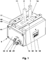
- the Figures 1 and 2 show a parallel gripper driven by an electric motor with two carriages (41, 42) equipped for picking up gripping elements (1, 2).
- the carriages (41, 42) and the drive (120), i.e. the motor (121), the gears (130, 140, 150) and parts of the control (24-27), are mounted in a base body or housing (10) .
- the base body (10) is a cuboid object made, for example, of an aluminum alloy.
- the dimensions of the base body (10) in the exemplary embodiment are in millimeters: 121 x 90 x 73.
- the base body (10) has two T-slot-shaped guide grooves (15, 16) on its upper side (11). These guide grooves (15, 16) run parallel to the longer body edges of the housing (10). Their distance from the center of the guide groove to the center of the guide groove is, for example, 38 mm.
- the guide surfaces of the guide grooves (15, 16) are hard-coated, i.e. the housing (10) is galvanically coated with a ceramic-like aluminum oxide layer at least in the area of the guide grooves (15, 16).
- Both carriages (41, 42) are guided in the guide grooves (15, 16) of the housing (10).
- Both carriages (41, 42) consist of a lower drive section (43) and an upper carriage web (45).
- the wider, lower drive section (43) has a toothed rack profile (151) on each side.
- the drive section (43) On the side facing away from the rack profile (151), the drive section (43) has a stop groove (44), each of which ends shortly before the end of the slide, forming a stop.
- a stop pin (21) engaging in the respective stop groove (44) is fastened in or on the housing (10).
- each carriage (41, 42) carries two centering sleeves (6) and three fastening bores (48), for example at the ends facing the respective outer end faces (47).
- the fastening bores (48) each have an internal thread below the cylinder countersinks.
- One gripping arm (1, 2) is placed on the centering sleeves (6) for each slide (41, 42).
- the gripping arms (1, 2) are each anchored in the corresponding fastening bores (48) using two screws (17).
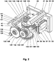
- the one-piece housing (10) there is a larger milled recess, which according to the Figures 1 and 2 can be closed at the rear by a separate cover (not shown here) and at the front by an electronics housing (23) accommodating the electronics (24-27).
- the electronics housing (23) and the cover are each fastened to the housing (10) using four countersunk screws.
- the electronics housing (23) has a multi-pole connection socket (29). If necessary, in the case of smaller gripping devices, the connection socket (29) is replaced by a cable which is passed through a PG screw connection and has a plug or socket at its free end.
- an electric motor (121) with an attached rotary encoder (125) is mounted in the base body (10) below the guide grooves (15, 16).
- the electric motor (121) is, for example, a brushless DC servomotor with a roller-bearing rotor.
- its nominal torque is 72 mNm.
- Its rated speed is approx. 4900 rpm, its rated power at 62 W.
- the rotary encoder located at the rear end of the shaft is a resolver.
- the latter has, for example, a diametrically magnetized two-pole transmitter magnet which is attached to the shaft of the electric motor (121).
- An angle sensor for detecting the motor shaft position is arranged behind the encoder magnet in the axial direction.
- the angle sensor comprises electronics with several Hall sensors, with at least one interpolator and with several driver stages.
- the angle-dependent analog magnetic field signal perceived by the Hall sensors is amplified and interpolated so that absolute angle information is produced with a resolution of approx. 5.27 angular minutes.
- the electric motor (121) acts on a worm gear (140) via, for example, a single-stage gear train (130), the spur gears of which are, for example, straight-toothed.
- the worm (143) of the worm shaft (141) meshes with a worm wheel (145) arranged on the synchronous hollow shaft (153).
- a 10-tooth pinion wheel (131), for example, is arranged on the output shaft of the electric motor (121).
- the center line (129) of the electric motor (121) is oriented parallel to the guide grooves (15, 16).
- the pinion wheel (131) meshes with, for example, a 36-tooth intermediate wheel (132).
- the latter drives a 24-tooth output gear (136) which is arranged on the worm shaft (141) of the worm gear (140).
- the worm (143) meshes with the 35-tooth worm wheel (145) arranged on the synchronous hollow shaft (153).
- the cylindrical worm (143) has a single start, for example.
- the worm (143) and the worm wheel (145) have vertically crossing center lines (149) and (159).
- the worm wheel (145) has pure helical teeth, the helix angle of which corresponds to the central pitch angle of the cylindrical worm (143). Because of the pure helical gearing, the worm wheel (145) is called a fake worm wheel.
- the tooth flanks of the gear pair only have one point of contact. The existing longitudinal sliding movement of the tooth flanks requires wear-resistant materials or hardened gears.
- the worm (143) and the worm wheel (145) are therefore each made of a nitriding steel 34CrAlNi7-10 and are correspondingly surface-hardened.
- the center line of the worm (143) does not have to lie in the central plane of the worm wheel toothing.
- the height may deviate from the center line (149) of the screw (143) in the millimeter range.
- the bearings of the worm shaft (141) can be seen on both sides of the worm (143).
- the synchronous hollow shaft (153) which is vertically oriented in the base body (10), carries the 16-tooth synchronous wheel (155) above the worm wheel (145), which in the exemplary embodiment meshes with the two rack profiles (151) of the carriages (41, 42).
- the synchronous hollow shaft (153) sits on roller bearings on a synchronous shaft axis (154) fixed to the housing.
- circuit boards (24-27) In the right-hand area of the inwardly open, cover-like electronics housing (23), there are some populated circuit boards (24-27).
- the circuit boards (24-27) are attached to the bottom of the tub in such a way that they protrude far into the interior of the housing (10).
- the respective protruding plate section has a length which is greater than 25% of the length of the housing (10).
- the plates (24-27) are oriented parallel to the vertical central longitudinal plane (8) of the housing (10).
- the circuit board (24) includes the computer and memory module (87). This board also has an angled board leg which extends along the large wall of the electronics housing. In addition to a data interface (86), the angled circuit board leg also has some light-emitting diodes (28) inserted into the wall of the electronics housing (23), visible from the outside, for the visual display of the operating state of the gripping device.
- the servo controller is located on the circuit board (25). It consists, among other things, of the servo controller CPU and other modules that prepare the motor signals for the cascade controller software.
- the circuit board (27) carries the power output stage, the control electronics of which are built on the circuit board (26) arranged in front of it.
- FIG 3 shows - as prior art - a conventional control of a conventional gripping device in a first interface layout plan.
- the control has two separate main assemblies (50, 70), which are housed, for example, in the control cabinet of the machine tool. They are summarized under the term "external control".
- the first main assembly is a programmable logic controller (50) with, for example, three PLC function assemblies (51, 52, 54).
- the first PLC function module (51) is the software for the machine and / or system.
- the PLC (50) generates control signals through internal microprocessors depending on internal software that is stored in the control's own program memory.
- the second PLC function module (52) is specially tailored application software for the gripping device to be controlled.
- a special program is used here for adaptation to the gripper's own control task in order to simulate the gripping device. The simulation is only possible within the limits of the PLC (50).
- the control hardware of the PLC (50) cannot be changed.
- the third PLC function module (54) forms a PLC-specific data interface that communicates with the second main module (70). Since the PLC (50) must be able to operate a large number of different sensors and actuators during process control, a field bus system is used for communication. All messages to be transmitted are sent to the fieldbus as digital telegrams or protocols and forwarded to the desired recipients via their addresses. For example, the Profibus, the Profi-Net-Bus, the Interbus-S or the CAN bus are used as the field bus system. These bus systems require specially shielded cables (55) for communication.
- the second main assembly (70) represents a universal servo controller. It has, for example, four controller functional units (71-74).
- the first controller functional unit (71) is the receiver side of the controller's own data interface. It is connected to the third PLC function module (54) via a shielded cable (55).
- the second Main assembly (70) supplied from an energy source (60) via a power cable (61).
- the second controller function unit (72) forms a programmed, closed cascade controller. It includes at least a position control, a speed control and a current control.
- the position control loop is usually equipped with a subordinate speed control loop.
- the cascade controller is also responsible, among other things, for the course of the positive and negative acceleration ramps of the electric motor (121) used in the gripping device.
- the third control function unit (73) is the control of the electric motor (121). It contains, among other things, a power output stage and its control electronics.
- the fourth controller function unit (74) represents the encoder interface (74) for communication with the motor-side encoder (125).
- the functional assemblies (51, 52, 54) are connected to the gripping device (5) via the controller functional units (71-74) as an external control via, for example, two shielded cables (76, 77).
- the gripping device (5) comprises, among other things, at least one servomotor (121) as electrical and / or electronic assemblies and at least one sensor (125) per servomotor for detecting the angular position of the motor shaft.
- the Figure 4 juxtaposes one in a second interface plan, among other things Figure 3 changed interface arrangement.
- the external control only contains the PLC (50) - as the first main assembly - with a first (51) and second PLC function assembly (53).
- the latter is an interface for point-to-point communication.
- Such communication can be implemented using the IO-Link ® system, for example.
- the system manages, for example, with a simple, unshielded two-wire connection (57).
- the two-wire connection (57) is combined with the power cable (61) to form an unshielded cable (56).
- the cable (57) is the only connection between the PLC (50) and the housing (10, 23) of the gripping device (5). So here is a simple, flexible and easy-to-use single-cable connection.
- the cable (57) is connected in the gripping device (5) to the point-to-point data interface (86) arranged there.
- the data interface (86) there is a computer and memory module (87) in the gripping device (5), which includes the entire gripper application software. All parameters required for gripping the workpieces by means of this gripping device (5) are stored in this module.
- these parameters include material properties that are, for example, a function of the modulus of elasticity or a hollowed-out geometry.
- the hardness according to Shore A, B, C or D can be specified in order to add the elasticity-related gripping stroke allowance as a geometric length in connection with the clamping width or clamping length between the gripping arms (1, 2), to calculate.
- the deformation-related spring rate can take the place of the Shore hardness.
- a servo controller (80) is connected to the servo motor (121) and the rotary encoder (125) in the gripping device (5) and is specially adapted to the combination of gripper kinematics, servo motor and rotary encoder.
- the first controller function unit of the individual servo controller (80) is a cascade controller (81), which manages, for example, with a position control loop without a speed controller, since the rotational speed or the lifting speed of the gripping arms is calculated from the angular position change supplied by the rotary encoder (125) and the runtime information.
- the gear ratios (130, 140, 150) are used, among other things.
- the second controller function unit (82) of the individual servo controller (80) is adapted to the performance and dynamics of the servo motor (121).
- the third controller function unit (83), the encoder interface, is tailored directly to the type of position or rotary encoder used. Components that allow universal access to other types of encoder, such as tacho generators, coil resolvers, optical measuring systems and the like, are omitted. This saves board space and energy.
- FIG. 5 shows a pneumatic circuit diagram for a gripping device (505), the drive or actuator of which is a cylinder-piston unit (160) operated with compressed air or hydraulic oil.
- the latter has a double-acting cylinder.
- two 3/2-way valves (200, 201) are connected upstream.
- the two directional control valves (200, 201) are pneumatic on both sides, for example Pre-controlled (211) and can be actuated on the flow side by an electromagnet (212) or an electromechanical drive.
- a line (244, 245) leading to the cylinder of the cylinder-piston unit (12) starts at the working connections (213) of the 3/2-way valves.
- the line (244) is responsible for the gripping stroke, while the line (245) supplies the cylinder with compressed air to release the workpiece.
- the two main inlets (233) on the directional control valve side are connected to the output of a proportional controller (250), which in turn is supplied via the compressed air connection on the housing side.
- the valve ventilation bores (249) of the directional control valves (200, 201) lead, for example, via bores inside the housing to a ventilation filter (227) arranged on the housing (10).
- 3/2-way valves (200, 201) are equipped with electromagnets (212), they are electrically controlled by the computer and storage module (170) via the control lines (217) or (218).
- the miniature proportional controller (250) built into the housing (10) has two electromagnetically controllable 2/2-way valves (251, 252), via which the compressed air from an external compressed air connection regulates the main inlets (233) of the 3/2-way valves (200, 201 ) is made available.
- the first 2/2-way valve (251) supplies the compressed air to the main inlets (233) via its working connection via the line (253).
- the second 2/2-way valve (252) vents the line (253) via the silencer (227) connected to its working connection.
- On the line (253) the pneumatic side of a pressure sensor (180) is connected.
- the pressure in the pressure sensor is converted into an electrical signal that represents the pressure in line (253).
- the signal is fed to an amplifier (261) and compared with the pressure present at the pressure sensor (180). If the measured pressure is too low, the amplifier (261) controls its output leading to the first 2/2-way valve (251) to open the valve (251).
- Figure 6 shows an interface layout plan for the control of a pneumatic gripping device (505) according to the circuit diagram Figure 5 .
- the gripping device comprises, among other things, at least two directional control valves (200, 201) as electrical and / or electronic assemblies, at least one position sensor (175) per cylinder-piston unit (160) and at least one pressure sensor ( 180).
- the control has a first main assembly (550), which is e.g. housed in the control cabinet of the machine tool. It is referred to as "external control”.
- This main assembly is a programmable logic controller (550) with e.g. two PLC function assemblies (551) and (553).
- the first PLC function module (551) is the software for the machine and / or system.
- the PLC generates control signals here through internal microprocessors depending on an internal one Software that is stored in the control's own program memory.
- the second PLC function module (553) forms a PLC-specific data interface that communicates with the second main module (580), the electronics of the gripping device (505). It is an interface for point-to-point communication. Such an exchange of information can be implemented using the IO-Link ® system, for example.
- the system manages, for example, with a simple, unshielded three- to five-wire connection (557).
- the multi-wire connection (557) is combined with the power cable (561) to form an unshielded cable (556), which then has, for example, two of five cores that are used for power supply.
- the cable (556) is the only connection between the PLC (550) and the housing of the gripping device (505). So here is a simple, flexible and easy-to-use single-cable connection.
- the cable (557) is connected in the gripping device (505) to the point-to-point data interface (586) arranged there.
- the data interface (586) there is a computer and memory module (170) in the gripping device, which includes the entire gripper application software. All parameters required for gripping the workpieces by means of this gripping device (505) are stored in this module.
- these parameters include material properties that are, for example, a function of the modulus of elasticity or a hollowed-out geometry.
- the hardness according to Shore A, B, C or D can be specified in order to add the elasticity-related gripping stroke allowance geometric length in connection with the clamping width or clamping length between the gripping arms (1, 2).
- the deformation-related spring rate can take the place of the Shore hardness.
- an individually constructed controller (580) is connected in the gripping device Position encoder, is matched.
- the individual controller (580) has at least one position controller (581) as a controller function unit, which manages, for example, with a position control loop, since the stroke speed of the gripping arms is calculated from the position change delivered by the position sensor or sensors (175) and the transit time information.
- a second regulator functional unit is a pressure regulator (582) which, with the help of the pressure sensors, determines e.g. the level of the feed pressure and the stroke direction of the gripping arms (1, 2) during the running time.
- the third controller functional unit is the sensor interface (583) of the individual controller (580). It is adapted to the performance and dynamics of the actuator (160) and tailored directly to at least one position transmitter (175) and, for example, one pressure sensor (180) per stroke direction of the actuator (160). With the help of the sensors (175, 180) installed on or in the gripping device, including the timer, the gripping time can also be measured in addition to measuring the gripping position and the applied pressure medium. In addition, statistical values such as the number of gripping processes or the amount of gripping forces can be collected. If necessary, an early warning of an imminent loss of function can also be generated. Such information is either forwarded to the PLC (550) or displayed on the gripping device (505), for example via LEDs or a display.
Landscapes
- Engineering & Computer Science (AREA)
- Robotics (AREA)
- Mechanical Engineering (AREA)
- Health & Medical Sciences (AREA)
- General Health & Medical Sciences (AREA)
- Orthopedic Medicine & Surgery (AREA)
- Human Computer Interaction (AREA)
- Manipulator (AREA)
- Jigs For Machine Tools (AREA)
- Feeding Of Workpieces (AREA)
Claims (11)
- Dispositif de préhension pour la préhension mécanique de pièces à usiner l'aide de bras préhenseurs (1, 2) mobiles, comprenant :- un boîtier (10, 23),- des bras préhenseurs mobiles (1, 2) et- un entraînement (120, 160) pneumatique ou hydraulique logé dans le boîtier (10, 23), qui entraîne les bras préhenseurs (1, 2) mobiles,
caractérisé- en ce que le boîtier de l'entraînement (120, 160) pneumatique ou hydraulique comporte au moins un capteur de position (175) et au moins un capteur de pression (180) et- en ce que dans ou directement sur le boîtier (10, 23) du dispositif de préhension (5, 505)- est placée premièrement une interface de données (86, 586) pour une communication point à point, pourvue d'un système de commande (50, 550) à mémoire programmable,- est placé deuxièmement au moins un module de calcul et de mémoire (87, 170), qui comprend le logiciel d'application du dispositif de préhension (5, 505) et- est placé troisièmement un régulateur (580) qui comporte au moins un régulateur de position (581), au moins un régulateur de pression (582), la commande de l'entraînement (160) pneumatique ou hydraulique et des interfaces (584) pour des capteurs de pression (180) et/ou au moins un système de mesure de déplacement ou de position (175). - Dispositif de préhension selon la revendication 1, caractérisé en ce que l'entraînement (160) pneumatique ou hydraulique est une unité piston-cylindre.
- Dispositif de préhension selon la revendication 1, caractérisé en ce que l'interface de données (86) et le module de calcul et de mémoire (87) sont logés sur au moins une carte de circuit imprimé (24 à 27).
- Dispositif de préhension pour la préhension mécanique de pièces à usiner l'aide de bras préhenseurs (1, 2) mobiles, comprenant :- un boîtier (10, 23),- des bras préhenseurs mobiles (1, 2) et- un entraînement (120, 160) électrique logé dans le boîtier (10, 23), qui entraîne les bras préhenseurs (1, 2) mobiles,- sur l'entraînement (120) électrique, soit le moteur d'entraînement (121) ayant un encodeur rotatif (125) ou au moins l'un des éléments constitutifs (41, 42) mus à l'aide des bras préhenseurs (1, 2) comportant un système de mesure de déplacement,- dans ou directement sur le boîtier (10, 23) du dispositif de préhension (5, 505)- étant placée premièrement une interface de données (86, 586) pour une communication point à point avec un système de commande (50, 550) à mémoire programmable,- étant placé deuxièmement un module de calcul et de mémoire (87, 170) qui comprend le logiciel d'application du dispositif de préhension (5, 505) et- étant placé troisièmement un servo-régulateur (80) qui comporte la commande du moteur d'entraînement (121) et qui comporte une interface d'encodeur (83) pour l'encodeur rotatif (125) ou le système de mesure de déplacement,
caractérisé- en ce que dans ou sur le boîtier (10, 23) du dispositif de préhension (5, 505) est placé le servo-régulateur (80) qui comporte un régulateur en cascade (81) fermé, le régulateur en cascade (81) comprenant au moins une régulation de position, une régulation de vitesse et une régulation de courant. - Dispositif de préhension selon la revendication 4, caractérisé en ce que le moteur d'entraînement (121) est un moteur DC sans balais.
- Dispositif de préhension selon la revendication 4, caractérisé en ce que l'encodeur rotatif (125) est un résolveur doté d'aimants émetteurs bipolaires et de plusieurs capteurs à effet Hall.
- Dispositif de préhension selon la revendication 4, caractérisé en ce que l'interface de données (86), le module de calcul et de mémoire (87) ainsi que l'ensemble du servo-régulateur (80) sont logés sur au moins une carte de circuit imprimé (24 à 27).
- Dispositif de préhension selon la revendication 3 ou 7, caractérisé en ce que la carte de circuit imprimé ou les cartes de circuit imprimé (24 à 27) sont fixées sur un couvercle ou sur un boîtier (23) apparent.
- Dispositif de préhension selon la revendication 3 ou 7, caractérisé en ce que dans le cas de plusieurs cartes de circuit imprimé (24 à 27), celles-ci sont empilées.
- Dispositif de préhension selon la revendication 8, caractérisé en ce que la carte de circuit imprimé ou les cartes de circuit imprimé (24-27) saillissent à l'intérieur de la zone du boîtier (10) dans laquelle sont logés le moteur d'entraînement (121) et les transmissions (130, 140, 150).
- Dispositif de préhension selon la revendication 1 ou 4, caractérisé en ce que le module de calcul et de mémoire (87, 170) est aménagé pour convertir au moins une partie des valeurs caractéristiques physiques détectées par les capteurs (125, 175, 180) en des signaux optiques ou acoustiques.
Applications Claiming Priority (3)
| Application Number | Priority Date | Filing Date | Title |
|---|---|---|---|
| DE102015012779.9A DE102015012779A1 (de) | 2015-10-05 | 2015-10-05 | Greifvorrichtung mit integriertem Servoregler |
| DE102016011761.3A DE102016011761A1 (de) | 2016-10-04 | 2016-10-04 | Greifvorrichtung mit Schaltmodul |
| PCT/DE2016/000360 WO2017059839A1 (fr) | 2015-10-05 | 2016-10-05 | Dispositif de préhension à régulateur intégré |
Publications (3)
| Publication Number | Publication Date |
|---|---|
| EP3359351A1 EP3359351A1 (fr) | 2018-08-15 |
| EP3359351B1 true EP3359351B1 (fr) | 2021-08-25 |
| EP3359351B2 EP3359351B2 (fr) | 2025-04-23 |
Family
ID=57286173
Family Applications (1)
| Application Number | Title | Priority Date | Filing Date |
|---|---|---|---|
| EP16794501.3A Active EP3359351B2 (fr) | 2015-10-05 | 2016-10-05 | Dispositif de préhension à régulateur intégré |
Country Status (4)
| Country | Link |
|---|---|
| EP (1) | EP3359351B2 (fr) |
| JP (1) | JP7050668B2 (fr) |
| CN (1) | CN108136581B (fr) |
| WO (1) | WO2017059839A1 (fr) |
Cited By (3)
| Publication number | Priority date | Publication date | Assignee | Title |
|---|---|---|---|---|
| US11606433B2 (en) * | 2018-03-12 | 2023-03-14 | Railnova Sa | Device for processing data of rolling stock |
| EP4230553A3 (fr) * | 2022-02-16 | 2023-10-18 | Günther Zimmer | Système de transport d'une cellule de fabrication |
| DE102022128993A1 (de) | 2022-11-02 | 2024-05-02 | Schunk Gmbh & Co. Kg Spann- Und Greiftechnik | Greif- oder Spannvorrichtung zum Greifen oder Spannen von Gegenständen in unterschiedlichen Betriebsmodi und Verfahren hierfür |
Families Citing this family (17)
| Publication number | Priority date | Publication date | Assignee | Title |
|---|---|---|---|---|
| US10252421B2 (en) * | 2015-10-06 | 2019-04-09 | Mtm Robotics Llc | Self-contained modular manufacturing tool |
| DE102017109291B4 (de) * | 2016-04-28 | 2019-12-24 | Karsten Weiß | Greifmodul |
| CN108445794B (zh) * | 2018-02-28 | 2021-08-27 | 辽宁科技大学 | 一种感应机器钳夹持控制器系统及控制方法 |
| CN108655298B (zh) * | 2018-06-15 | 2024-10-29 | 东莞市龙顺智能科技有限公司 | 芯线刷直机构 |
| US11192245B2 (en) | 2018-12-21 | 2021-12-07 | The Boeing Company | Independent end-effector control and operation |
| EP3670111A3 (fr) * | 2018-12-21 | 2020-08-26 | The Boeing Company | Commande et fonctionnement indépendants d'effecteur d'extrémité |
| NL2022405B1 (en) * | 2019-01-16 | 2020-08-14 | Boeing Co | Independent end-effector control and operation |
| IT201900006668A1 (it) * | 2019-05-09 | 2020-11-09 | Gimatic S R L | Pinza per manipolatori industriali dotata di sensore e metodo per rilevare la presenza di un pezzo tra le griffe di una pinza per manipolatori industriali |
| JP7448739B2 (ja) * | 2019-05-27 | 2024-03-13 | Smc株式会社 | チャック装置の駆動システム及びその制御方法 |
| CN110328565A (zh) * | 2019-08-19 | 2019-10-15 | 丹阳河工工具有限公司 | 一种用于丝锥磨削的装夹装置 |
| CN112571406A (zh) * | 2020-11-30 | 2021-03-30 | 山东大学日照智能制造研究院 | 一种电液混合驱动特种机器人及控制方法 |
| DE102020007794B3 (de) * | 2020-12-19 | 2022-04-07 | Günther Zimmer | Handhabungssystem mit externer Steuerbaugruppe |
| JP7810521B2 (ja) * | 2021-02-18 | 2026-02-03 | Smc株式会社 | 開閉チャックおよびそのフィンガの製造方法 |
| DE102021108803A1 (de) * | 2021-04-08 | 2022-10-13 | Deckel Maho Pfronten Gmbh | System zur Werkstückbearbeitung, Werkzeugmaschine, Trägervorrichtung und Werkstückträger |
| DE102021002418B3 (de) * | 2021-05-07 | 2022-07-14 | Günther Zimmer | Verfahren zum Erstellen von Greiferablaufprogrammen |
| DE102023126240A1 (de) * | 2023-09-27 | 2025-03-27 | Festo Se & Co. Kg | Verfahren und Vorrichtung zum Ermitteln einer Kolben- oder Radposition |
| CN118763952B (zh) * | 2024-09-06 | 2024-12-06 | 珠海市吉力电机技术有限公司 | 云电机及云电机的控制方法 |
Citations (8)
| Publication number | Priority date | Publication date | Assignee | Title |
|---|---|---|---|---|
| EP0205141A2 (fr) | 1985-06-12 | 1986-12-17 | BULL HN INFORMATION SYSTEMS ITALIA S.p.A. | Dispositif de préhension pneumatique autoprogrammé |
| DE3336778C2 (fr) | 1983-10-10 | 1991-06-06 | Rudi 4018 Langenfeld De Kirst | |
| US6463835B1 (en) | 1998-10-23 | 2002-10-15 | Hitachi Seiki Co., Ltd. | Method and apparatus for controlling motor-driven chucking device |
| EP1250977A1 (fr) | 2001-04-20 | 2002-10-23 | Schunk GmbH & Co KG Fabrik für Spann- und Greifwerkzeuge | Unité de rotation et système de transmission de fluide associé |
| DE10355250A1 (de) | 2003-11-26 | 2005-06-30 | Festo Ag & Co. | Verfahren und Vorrichtung zur Leckage-Ermittlung |
| DE102007055460A1 (de) | 2007-11-12 | 2009-05-20 | Gas - Automation Gmbh | Ventilblock |
| US20100123325A1 (en) | 2008-11-20 | 2010-05-20 | Giuseppe Maffeis | Pneumatically controlled grasping device |
| US20140156066A1 (en) | 2012-11-30 | 2014-06-05 | Fanuc Corporation | Electric hand with a force sensor |
Family Cites Families (7)
| Publication number | Priority date | Publication date | Assignee | Title |
|---|---|---|---|---|
| JPH05305593A (ja) * | 1992-04-28 | 1993-11-19 | Toyooki Kogyo Co Ltd | 物品挾持装置 |
| DE102006045783B4 (de) | 2006-09-26 | 2008-06-26 | Zimmer, Günther | Greifvorrichtung mit räumlichem Schraubgetriebe |
| WO2012032591A1 (fr) | 2010-09-06 | 2012-03-15 | 三菱電機株式会社 | Machine électrique tournante du type à aimant permanent et dispositif de direction assistée utilisant cette machine |
| JP5543539B2 (ja) * | 2012-07-25 | 2014-07-09 | ファナック株式会社 | 力制御電動ハンド |
| JP5480340B2 (ja) * | 2012-07-26 | 2014-04-23 | ファナック株式会社 | ローラ装置を用いた取出しロボットシステム |
| JP2014046449A (ja) * | 2012-09-04 | 2014-03-17 | Canon Inc | ロボットハンド制御方法、ロボットハンド制御装置及びロボット装置 |
| CN203390935U (zh) * | 2013-08-19 | 2014-01-15 | 上海观奇自动化系统有限公司 | 轮辐抓取装置 |
-
2016
- 2016-10-05 CN CN201680058737.6A patent/CN108136581B/zh active Active
- 2016-10-05 JP JP2018517415A patent/JP7050668B2/ja active Active
- 2016-10-05 EP EP16794501.3A patent/EP3359351B2/fr active Active
- 2016-10-05 WO PCT/DE2016/000360 patent/WO2017059839A1/fr not_active Ceased
Patent Citations (8)
| Publication number | Priority date | Publication date | Assignee | Title |
|---|---|---|---|---|
| DE3336778C2 (fr) | 1983-10-10 | 1991-06-06 | Rudi 4018 Langenfeld De Kirst | |
| EP0205141A2 (fr) | 1985-06-12 | 1986-12-17 | BULL HN INFORMATION SYSTEMS ITALIA S.p.A. | Dispositif de préhension pneumatique autoprogrammé |
| US6463835B1 (en) | 1998-10-23 | 2002-10-15 | Hitachi Seiki Co., Ltd. | Method and apparatus for controlling motor-driven chucking device |
| EP1250977A1 (fr) | 2001-04-20 | 2002-10-23 | Schunk GmbH & Co KG Fabrik für Spann- und Greifwerkzeuge | Unité de rotation et système de transmission de fluide associé |
| DE10355250A1 (de) | 2003-11-26 | 2005-06-30 | Festo Ag & Co. | Verfahren und Vorrichtung zur Leckage-Ermittlung |
| DE102007055460A1 (de) | 2007-11-12 | 2009-05-20 | Gas - Automation Gmbh | Ventilblock |
| US20100123325A1 (en) | 2008-11-20 | 2010-05-20 | Giuseppe Maffeis | Pneumatically controlled grasping device |
| US20140156066A1 (en) | 2012-11-30 | 2014-06-05 | Fanuc Corporation | Electric hand with a force sensor |
Non-Patent Citations (7)
| Title |
|---|
| "Elektrische Antriebstechnik. Siemens", 1 January 2008, article WEIDAUER JENS: "6.2. Systematik der Servoantriebe", pages: 128 - 129, XP055928723 |
| ANONYMOUS: "Motion Control Schunk V 1.60 Motion Control Schunk", SCHUNK - SOFTWARE HANDBUCH, 14 September 2015 (2015-09-14), pages 1 - 199, XP055928711, Retrieved from the Internet <URL:https://schunk.com/fileadmin/pim/docs/IM0010975.PDF> [retrieved on 20220608] |
| ANONYMOUS: "Proportional-Druckregelventile MPPE/ MPPES", FESTO - PROPORTIONALTECHNIK, 1 January 2004 (2004-01-01), XP055928736, [retrieved on 20220608] |
| ANONYMOUS: "Proportional-Druckregelventile MPPE/MPPES", FESTO, 1 March 2013 (2013-03-01), pages 1 - 14, XP055928731, Retrieved from the Internet <URL:https://www.festo.com/cat/xdki/data/doc_de/PDF/DE/MPPE-MPPES_DE.PDF> [retrieved on 20220608] |
| ANONYMOUS: "WEB 144dpiRGB", SCHUNK GREIFER - KATALOG, 1 August 2015 (2015-08-01), XP055928691, [retrieved on 20220608] |
| PRODUKTINFORMATION UNIVERSALGREIFER EGL, 2020 |
| SCHUNK HIGHLIGHTS GREIFSYSTEME DE |
Cited By (4)
| Publication number | Priority date | Publication date | Assignee | Title |
|---|---|---|---|---|
| US11606433B2 (en) * | 2018-03-12 | 2023-03-14 | Railnova Sa | Device for processing data of rolling stock |
| EP4230553A3 (fr) * | 2022-02-16 | 2023-10-18 | Günther Zimmer | Système de transport d'une cellule de fabrication |
| DE102022128993A1 (de) | 2022-11-02 | 2024-05-02 | Schunk Gmbh & Co. Kg Spann- Und Greiftechnik | Greif- oder Spannvorrichtung zum Greifen oder Spannen von Gegenständen in unterschiedlichen Betriebsmodi und Verfahren hierfür |
| WO2024094774A1 (fr) | 2022-11-02 | 2024-05-10 | Schunk Se & Co. Kg Spanntechnik Greiftechnik Automatisierungstechnik | Dispositif de préhension ou de serrage pour saisir ou serrer des objets dans différents modes de fonctionnement et procédé associé |
Also Published As
| Publication number | Publication date |
|---|---|
| EP3359351B2 (fr) | 2025-04-23 |
| JP2019500223A (ja) | 2019-01-10 |
| EP3359351A1 (fr) | 2018-08-15 |
| WO2017059839A1 (fr) | 2017-04-13 |
| CN108136581B (zh) | 2021-11-02 |
| CN108136581A (zh) | 2018-06-08 |
| JP7050668B2 (ja) | 2022-04-08 |
Similar Documents
| Publication | Publication Date | Title |
|---|---|---|
| EP3359351B1 (fr) | Dispositif de préhension à régulateur intégré | |
| DE102015012779A1 (de) | Greifvorrichtung mit integriertem Servoregler | |
| DE102012021387B3 (de) | Elektropneumatisches Feldgerät und elektropneumatische Baugruppe | |
| EP2024712B1 (fr) | Dispositif pour la transmission de valeurs de mesure | |
| EP2093642B1 (fr) | Table rotative avec une unité de contrôle ou regulation associée | |
| DE102009022891B3 (de) | Verfahren zur elektronischen Verschleißzustandsermittlung bei einer Ventilanordnung | |
| EP2149831B1 (fr) | Procédé de commande pour un composite comprenant plusieurs appareils de manutention multiaxiaux disposés les uns derrière les autres et/ou les uns à côté des autres ainsi que support de stockage de données, système de commande et composite | |
| EP4017826B1 (fr) | Unité de commande et procédé d'actionnement d'un moyen de transport | |
| EP0929845B1 (fr) | Dispositif intelligent de commande et de regulation | |
| EP3523101B1 (fr) | Dispositif de préhension muni d'un module de commutation | |
| DE10333067B4 (de) | Elektrisches Stellglied und Verfahren zur Steuerung desselben | |
| EP0345665B1 (fr) | Méthode et dispositif pour contrôler la position d'une vanne de commande | |
| WO2008019938A1 (fr) | Dispositif d'accouplement | |
| EP3458201B1 (fr) | Pompe à agent de revêtement | |
| EP3578295A1 (fr) | Dispositif de mesure de position et procédé de fonctionnement d'un dispositif de mesure de position | |
| DE102015210716B4 (de) | Positionssensor sowie Verfahren zum Betreiben eines Positionssensors | |
| DE102009004569A1 (de) | Verfahren und elektronische Einrichtung zur Kompensation der Hysterese von pneumatisch angetriebenen Armaturen | |
| EP1136264B1 (fr) | Dispositif et procédé pour commander des zones d'encrage | |
| DE102007010115A1 (de) | Pneumatikantrieb mit Zylinderschalter | |
| WO1985002921A1 (fr) | Installation de determination des valeurs de consigne pour le transport des pieces a usiner d'une presse a paliers multiples | |
| DE102014017413B3 (de) | Automatisierungssystem zur automatisierten Bereitstellung einer Arbeitsbewegung und Verfahren zum Betreiben eines Automatisierungssystems | |
| EP0490375A1 (fr) | Réglage par multiple uP-NC pour multiple axes de machines-outils | |
| DE19924201A1 (de) | Verfahren und Vorrichtung zur Drehzahl- und/oder Drehrichtungserfassung von Motoren | |
| DE202009010293U1 (de) | Elektronisches Auswertemodul für Sensorsignale | |
| DE102004024883B4 (de) | Antriebssystem |
Legal Events
| Date | Code | Title | Description |
|---|---|---|---|
| STAA | Information on the status of an ep patent application or granted ep patent |
Free format text: STATUS: UNKNOWN |
|
| STAA | Information on the status of an ep patent application or granted ep patent |
Free format text: STATUS: THE INTERNATIONAL PUBLICATION HAS BEEN MADE |
|
| PUAI | Public reference made under article 153(3) epc to a published international application that has entered the european phase |
Free format text: ORIGINAL CODE: 0009012 |
|
| STAA | Information on the status of an ep patent application or granted ep patent |
Free format text: STATUS: REQUEST FOR EXAMINATION WAS MADE |
|
| 17P | Request for examination filed |
Effective date: 20180418 |
|
| AK | Designated contracting states |
Kind code of ref document: A1 Designated state(s): AL AT BE BG CH CY CZ DE DK EE ES FI FR GB GR HR HU IE IS IT LI LT LU LV MC MK MT NL NO PL PT RO RS SE SI SK SM TR |
|
| AX | Request for extension of the european patent |
Extension state: BA ME |
|
| DAV | Request for validation of the european patent (deleted) | ||
| DAX | Request for extension of the european patent (deleted) | ||
| STAA | Information on the status of an ep patent application or granted ep patent |
Free format text: STATUS: EXAMINATION IS IN PROGRESS |
|
| 17Q | First examination report despatched |
Effective date: 20210401 |
|
| GRAP | Despatch of communication of intention to grant a patent |
Free format text: ORIGINAL CODE: EPIDOSNIGR1 |
|
| STAA | Information on the status of an ep patent application or granted ep patent |
Free format text: STATUS: GRANT OF PATENT IS INTENDED |
|
| RIC1 | Information provided on ipc code assigned before grant |
Ipc: B25J 15/02 20060101ALI20210512BHEP Ipc: B25J 13/08 20060101ALI20210512BHEP Ipc: B25J 9/16 20060101AFI20210512BHEP |
|
| GRAJ | Information related to disapproval of communication of intention to grant by the applicant or resumption of examination proceedings by the epo deleted |
Free format text: ORIGINAL CODE: EPIDOSDIGR1 |
|
| STAA | Information on the status of an ep patent application or granted ep patent |
Free format text: STATUS: EXAMINATION IS IN PROGRESS |
|
| GRAJ | Information related to disapproval of communication of intention to grant by the applicant or resumption of examination proceedings by the epo deleted |
Free format text: ORIGINAL CODE: EPIDOSDIGR1 |
|
| INTG | Intention to grant announced |
Effective date: 20210607 |
|
| STAA | Information on the status of an ep patent application or granted ep patent |
Free format text: STATUS: GRANT OF PATENT IS INTENDED |
|
| GRAP | Despatch of communication of intention to grant a patent |
Free format text: ORIGINAL CODE: EPIDOSNIGR1 |
|
| GRAS | Grant fee paid |
Free format text: ORIGINAL CODE: EPIDOSNIGR3 |
|
| GRAA | (expected) grant |
Free format text: ORIGINAL CODE: 0009210 |
|
| STAA | Information on the status of an ep patent application or granted ep patent |
Free format text: STATUS: THE PATENT HAS BEEN GRANTED |
|
| INTC | Intention to grant announced (deleted) | ||
| INTG | Intention to grant announced |
Effective date: 20210707 |
|
| AK | Designated contracting states |
Kind code of ref document: B1 Designated state(s): AL AT BE BG CH CY CZ DE DK EE ES FI FR GB GR HR HU IE IS IT LI LT LU LV MC MK MT NL NO PL PT RO RS SE SI SK SM TR |
|
| REG | Reference to a national code |
Ref country code: CH Ref legal event code: EP |
|
| REG | Reference to a national code |
Ref country code: DE Ref legal event code: R096 Ref document number: 502016013711 Country of ref document: DE |
|
| REG | Reference to a national code |
Ref country code: IE Ref legal event code: FG4D Free format text: LANGUAGE OF EP DOCUMENT: GERMAN Ref country code: AT Ref legal event code: REF Ref document number: 1423311 Country of ref document: AT Kind code of ref document: T Effective date: 20210915 |
|
| REG | Reference to a national code |
Ref country code: LT Ref legal event code: MG9D |
|
| REG | Reference to a national code |
Ref country code: NL Ref legal event code: MP Effective date: 20210825 |
|
| PG25 | Lapsed in a contracting state [announced via postgrant information from national office to epo] |
Ref country code: RS Free format text: LAPSE BECAUSE OF FAILURE TO SUBMIT A TRANSLATION OF THE DESCRIPTION OR TO PAY THE FEE WITHIN THE PRESCRIBED TIME-LIMIT Effective date: 20210825 Ref country code: SE Free format text: LAPSE BECAUSE OF FAILURE TO SUBMIT A TRANSLATION OF THE DESCRIPTION OR TO PAY THE FEE WITHIN THE PRESCRIBED TIME-LIMIT Effective date: 20210825 Ref country code: BG Free format text: LAPSE BECAUSE OF FAILURE TO SUBMIT A TRANSLATION OF THE DESCRIPTION OR TO PAY THE FEE WITHIN THE PRESCRIBED TIME-LIMIT Effective date: 20211125 Ref country code: LT Free format text: LAPSE BECAUSE OF FAILURE TO SUBMIT A TRANSLATION OF THE DESCRIPTION OR TO PAY THE FEE WITHIN THE PRESCRIBED TIME-LIMIT Effective date: 20210825 Ref country code: PT Free format text: LAPSE BECAUSE OF FAILURE TO SUBMIT A TRANSLATION OF THE DESCRIPTION OR TO PAY THE FEE WITHIN THE PRESCRIBED TIME-LIMIT Effective date: 20211227 Ref country code: NO Free format text: LAPSE BECAUSE OF FAILURE TO SUBMIT A TRANSLATION OF THE DESCRIPTION OR TO PAY THE FEE WITHIN THE PRESCRIBED TIME-LIMIT Effective date: 20211125 Ref country code: ES Free format text: LAPSE BECAUSE OF FAILURE TO SUBMIT A TRANSLATION OF THE DESCRIPTION OR TO PAY THE FEE WITHIN THE PRESCRIBED TIME-LIMIT Effective date: 20210825 Ref country code: FI Free format text: LAPSE BECAUSE OF FAILURE TO SUBMIT A TRANSLATION OF THE DESCRIPTION OR TO PAY THE FEE WITHIN THE PRESCRIBED TIME-LIMIT Effective date: 20210825 Ref country code: HR Free format text: LAPSE BECAUSE OF FAILURE TO SUBMIT A TRANSLATION OF THE DESCRIPTION OR TO PAY THE FEE WITHIN THE PRESCRIBED TIME-LIMIT Effective date: 20210825 |
|
| PG25 | Lapsed in a contracting state [announced via postgrant information from national office to epo] |
Ref country code: PL Free format text: LAPSE BECAUSE OF FAILURE TO SUBMIT A TRANSLATION OF THE DESCRIPTION OR TO PAY THE FEE WITHIN THE PRESCRIBED TIME-LIMIT Effective date: 20210825 Ref country code: LV Free format text: LAPSE BECAUSE OF FAILURE TO SUBMIT A TRANSLATION OF THE DESCRIPTION OR TO PAY THE FEE WITHIN THE PRESCRIBED TIME-LIMIT Effective date: 20210825 Ref country code: GR Free format text: LAPSE BECAUSE OF FAILURE TO SUBMIT A TRANSLATION OF THE DESCRIPTION OR TO PAY THE FEE WITHIN THE PRESCRIBED TIME-LIMIT Effective date: 20211126 |
|
| PG25 | Lapsed in a contracting state [announced via postgrant information from national office to epo] |
Ref country code: NL Free format text: LAPSE BECAUSE OF FAILURE TO SUBMIT A TRANSLATION OF THE DESCRIPTION OR TO PAY THE FEE WITHIN THE PRESCRIBED TIME-LIMIT Effective date: 20210825 |
|
| PG25 | Lapsed in a contracting state [announced via postgrant information from national office to epo] |
Ref country code: DK Free format text: LAPSE BECAUSE OF FAILURE TO SUBMIT A TRANSLATION OF THE DESCRIPTION OR TO PAY THE FEE WITHIN THE PRESCRIBED TIME-LIMIT Effective date: 20210825 |
|
| REG | Reference to a national code |
Ref country code: DE Ref legal event code: R026 Ref document number: 502016013711 Country of ref document: DE |
|
| PLBI | Opposition filed |
Free format text: ORIGINAL CODE: 0009260 |
|
| REG | Reference to a national code |
Ref country code: CH Ref legal event code: PL |
|
| PG25 | Lapsed in a contracting state [announced via postgrant information from national office to epo] |
Ref country code: SM Free format text: LAPSE BECAUSE OF FAILURE TO SUBMIT A TRANSLATION OF THE DESCRIPTION OR TO PAY THE FEE WITHIN THE PRESCRIBED TIME-LIMIT Effective date: 20210825 Ref country code: SK Free format text: LAPSE BECAUSE OF FAILURE TO SUBMIT A TRANSLATION OF THE DESCRIPTION OR TO PAY THE FEE WITHIN THE PRESCRIBED TIME-LIMIT Effective date: 20210825 Ref country code: RO Free format text: LAPSE BECAUSE OF FAILURE TO SUBMIT A TRANSLATION OF THE DESCRIPTION OR TO PAY THE FEE WITHIN THE PRESCRIBED TIME-LIMIT Effective date: 20210825 Ref country code: EE Free format text: LAPSE BECAUSE OF FAILURE TO SUBMIT A TRANSLATION OF THE DESCRIPTION OR TO PAY THE FEE WITHIN THE PRESCRIBED TIME-LIMIT Effective date: 20210825 Ref country code: CZ Free format text: LAPSE BECAUSE OF FAILURE TO SUBMIT A TRANSLATION OF THE DESCRIPTION OR TO PAY THE FEE WITHIN THE PRESCRIBED TIME-LIMIT Effective date: 20210825 Ref country code: AL Free format text: LAPSE BECAUSE OF FAILURE TO SUBMIT A TRANSLATION OF THE DESCRIPTION OR TO PAY THE FEE WITHIN THE PRESCRIBED TIME-LIMIT Effective date: 20210825 |
|
| PLAB | Opposition data, opponent's data or that of the opponent's representative modified |
Free format text: ORIGINAL CODE: 0009299OPPO |
|
| PLAX | Notice of opposition and request to file observation + time limit sent |
Free format text: ORIGINAL CODE: EPIDOSNOBS2 |
|
| REG | Reference to a national code |
Ref country code: BE Ref legal event code: MM Effective date: 20211031 |
|
| 26 | Opposition filed |
Opponent name: SCHUNK GMBH & CO. KG SPANN- UND GREIFTECHNIK Effective date: 20220523 |
|
| PG25 | Lapsed in a contracting state [announced via postgrant information from national office to epo] |
Ref country code: MC Free format text: LAPSE BECAUSE OF FAILURE TO SUBMIT A TRANSLATION OF THE DESCRIPTION OR TO PAY THE FEE WITHIN THE PRESCRIBED TIME-LIMIT Effective date: 20210825 |
|
| R26 | Opposition filed (corrected) |
Opponent name: SCHUNK GMBH & CO. KG SPANN- UND GREIFTECHNIK Effective date: 20220523 |
|
| PG25 | Lapsed in a contracting state [announced via postgrant information from national office to epo] |
Ref country code: LU Free format text: LAPSE BECAUSE OF NON-PAYMENT OF DUE FEES Effective date: 20211005 Ref country code: BE Free format text: LAPSE BECAUSE OF NON-PAYMENT OF DUE FEES Effective date: 20211031 |
|
| PG25 | Lapsed in a contracting state [announced via postgrant information from national office to epo] |
Ref country code: SI Free format text: LAPSE BECAUSE OF FAILURE TO SUBMIT A TRANSLATION OF THE DESCRIPTION OR TO PAY THE FEE WITHIN THE PRESCRIBED TIME-LIMIT Effective date: 20210825 Ref country code: LI Free format text: LAPSE BECAUSE OF NON-PAYMENT OF DUE FEES Effective date: 20211031 Ref country code: CH Free format text: LAPSE BECAUSE OF NON-PAYMENT OF DUE FEES Effective date: 20211031 |
|
| PLBB | Reply of patent proprietor to notice(s) of opposition received |
Free format text: ORIGINAL CODE: EPIDOSNOBS3 |
|
| PG25 | Lapsed in a contracting state [announced via postgrant information from national office to epo] |
Ref country code: IE Free format text: LAPSE BECAUSE OF NON-PAYMENT OF DUE FEES Effective date: 20211005 |
|
| REG | Reference to a national code |
Ref country code: AT Ref legal event code: MM01 Ref document number: 1423311 Country of ref document: AT Kind code of ref document: T Effective date: 20211005 |
|
| PG25 | Lapsed in a contracting state [announced via postgrant information from national office to epo] |
Ref country code: AT Free format text: LAPSE BECAUSE OF NON-PAYMENT OF DUE FEES Effective date: 20211005 |
|
| PG25 | Lapsed in a contracting state [announced via postgrant information from national office to epo] |
Ref country code: HU Free format text: LAPSE BECAUSE OF FAILURE TO SUBMIT A TRANSLATION OF THE DESCRIPTION OR TO PAY THE FEE WITHIN THE PRESCRIBED TIME-LIMIT; INVALID AB INITIO Effective date: 20161005 |
|
| PG25 | Lapsed in a contracting state [announced via postgrant information from national office to epo] |
Ref country code: CY Free format text: LAPSE BECAUSE OF FAILURE TO SUBMIT A TRANSLATION OF THE DESCRIPTION OR TO PAY THE FEE WITHIN THE PRESCRIBED TIME-LIMIT Effective date: 20210825 |
|
| PG25 | Lapsed in a contracting state [announced via postgrant information from national office to epo] |
Ref country code: MK Free format text: LAPSE BECAUSE OF FAILURE TO SUBMIT A TRANSLATION OF THE DESCRIPTION OR TO PAY THE FEE WITHIN THE PRESCRIBED TIME-LIMIT Effective date: 20210825 |
|
| PLBP | Opposition withdrawn |
Free format text: ORIGINAL CODE: 0009264 |
|
| PG25 | Lapsed in a contracting state [announced via postgrant information from national office to epo] |
Ref country code: MT Free format text: LAPSE BECAUSE OF FAILURE TO SUBMIT A TRANSLATION OF THE DESCRIPTION OR TO PAY THE FEE WITHIN THE PRESCRIBED TIME-LIMIT Effective date: 20210825 |
|
| PUAH | Patent maintained in amended form |
Free format text: ORIGINAL CODE: 0009272 |
|
| STAA | Information on the status of an ep patent application or granted ep patent |
Free format text: STATUS: PATENT MAINTAINED AS AMENDED |
|
| 27A | Patent maintained in amended form |
Effective date: 20250423 |
|
| AK | Designated contracting states |
Kind code of ref document: B2 Designated state(s): AL AT BE BG CH CY CZ DE DK EE ES FI FR GB GR HR HU IE IS IT LI LT LU LV MC MK MT NL NO PL PT RO RS SE SI SK SM TR |
|
| REG | Reference to a national code |
Ref country code: DE Ref legal event code: R102 Ref document number: 502016013711 Country of ref document: DE |
|
| PG25 | Lapsed in a contracting state [announced via postgrant information from national office to epo] |
Ref country code: TR Free format text: LAPSE BECAUSE OF FAILURE TO SUBMIT A TRANSLATION OF THE DESCRIPTION OR TO PAY THE FEE WITHIN THE PRESCRIBED TIME-LIMIT Effective date: 20210825 |
|
| PGFP | Annual fee paid to national office [announced via postgrant information from national office to epo] |
Ref country code: DE Payment date: 20251014 Year of fee payment: 10 |
|
| PGFP | Annual fee paid to national office [announced via postgrant information from national office to epo] |
Ref country code: GB Payment date: 20251024 Year of fee payment: 10 |
|
| PGFP | Annual fee paid to national office [announced via postgrant information from national office to epo] |
Ref country code: IT Payment date: 20251030 Year of fee payment: 10 |
|
| PGFP | Annual fee paid to national office [announced via postgrant information from national office to epo] |
Ref country code: FR Payment date: 20251024 Year of fee payment: 10 |